US4610673A - Gastroenteric feeding tube - Google Patents
Gastroenteric feeding tubeDownload PDFInfo
- Publication number
- US4610673A US4610673AUS06/703,319US70331985AUS4610673AUS 4610673 AUS4610673 AUS 4610673AUS 70331985 AUS70331985 AUS 70331985AUS 4610673 AUS4610673 AUS 4610673A
- Authority
- US
- United States
- Prior art keywords
- intermediate portion
- shaft
- tube
- patient
- feeding
- Prior art date
- Legal status (The legal status is an assumption and is not a legal conclusion. Google has not performed a legal analysis and makes no representation as to the accuracy of the status listed.)
- Expired - Lifetime
Links
- 238000009434installationMethods0.000claimsdescription13
- 239000000463materialSubstances0.000claimsdescription10
- 239000004721Polyphenylene oxideSubstances0.000claimsdescription9
- 229920000570polyetherPolymers0.000claimsdescription9
- 229920002635polyurethanePolymers0.000claimsdescription9
- 239000004814polyurethaneSubstances0.000claimsdescription9
- 238000002627tracheal intubationMethods0.000abstractdescription4
- 210000002784stomachAnatomy0.000description10
- 210000000936intestineAnatomy0.000description6
- 208000014674injuryDiseases0.000description5
- 210000001630jejunumAnatomy0.000description5
- 235000016709nutritionNutrition0.000description5
- 230000002035prolonged effectEffects0.000description5
- 206010067171RegurgitationDiseases0.000description3
- 230000006378damageEffects0.000description3
- 210000003238esophagusAnatomy0.000description3
- 210000001156gastric mucosaAnatomy0.000description3
- 238000000034methodMethods0.000description3
- 230000008733traumaEffects0.000description3
- 208000027418Wounds and injuryDiseases0.000description2
- 239000000853adhesiveSubstances0.000description2
- 230000001070adhesive effectEffects0.000description2
- 230000007794irritationEffects0.000description2
- 210000004072lungAnatomy0.000description2
- 208000002720MalnutritionDiseases0.000description1
- 239000004677NylonSubstances0.000description1
- 150000001875compoundsChemical class0.000description1
- 230000007797corrosionEffects0.000description1
- 238000005260corrosionMethods0.000description1
- 230000000694effectsEffects0.000description1
- 238000001990intravenous administrationMethods0.000description1
- 230000001071malnutritionEffects0.000description1
- 235000000824malnutritionNutrition0.000description1
- 238000004519manufacturing processMethods0.000description1
- 239000002184metalSubstances0.000description1
- 238000012986modificationMethods0.000description1
- 230000004048modificationEffects0.000description1
- 238000000465mouldingMethods0.000description1
- 231100000252nontoxicToxicity0.000description1
- 230000003000nontoxic effectEffects0.000description1
- 208000015380nutritional deficiency diseaseDiseases0.000description1
- 229920001778nylonPolymers0.000description1
- 210000003800pharynxAnatomy0.000description1
- 229920001296polysiloxanePolymers0.000description1
- 230000008707rearrangementEffects0.000description1
- 229920002379silicone rubberPolymers0.000description1
- 239000004945silicone rubberSubstances0.000description1
- 229910001220stainless steelInorganic materials0.000description1
- 239000010935stainless steelSubstances0.000description1
- 230000004580weight lossEffects0.000description1
Images
Classifications
- A—HUMAN NECESSITIES
- A61—MEDICAL OR VETERINARY SCIENCE; HYGIENE
- A61J—CONTAINERS SPECIALLY ADAPTED FOR MEDICAL OR PHARMACEUTICAL PURPOSES; DEVICES OR METHODS SPECIALLY ADAPTED FOR BRINGING PHARMACEUTICAL PRODUCTS INTO PARTICULAR PHYSICAL OR ADMINISTERING FORMS; DEVICES FOR ADMINISTERING FOOD OR MEDICINES ORALLY; BABY COMFORTERS; DEVICES FOR RECEIVING SPITTLE
- A61J15/00—Feeding-tubes for therapeutic purposes
- A61J15/0003—Nasal or oral feeding-tubes, e.g. tube entering body through nose or mouth
- A—HUMAN NECESSITIES
- A61—MEDICAL OR VETERINARY SCIENCE; HYGIENE
- A61J—CONTAINERS SPECIALLY ADAPTED FOR MEDICAL OR PHARMACEUTICAL PURPOSES; DEVICES OR METHODS SPECIALLY ADAPTED FOR BRINGING PHARMACEUTICAL PRODUCTS INTO PARTICULAR PHYSICAL OR ADMINISTERING FORMS; DEVICES FOR ADMINISTERING FOOD OR MEDICINES ORALLY; BABY COMFORTERS; DEVICES FOR RECEIVING SPITTLE
- A61J15/00—Feeding-tubes for therapeutic purposes
- A61J15/0026—Parts, details or accessories for feeding-tubes
- A61J15/0069—Tubes feeding directly to the intestines, e.g. to the jejunum
Definitions
- the instant inventionrelates to medical equipment, and more particularly to a gastroenteric feeding tube for the enteral feeding of a patient by tube.
- enteral feedingis accomplished through the use of a gastroenteric feeding tube which is installed in a patient so that it extends through a nostril, through the esophagus, into the stomach and sometimes into the jejunum area of the intestines of the patient.
- a gastroenteric feeding tubewhich is installed in a patient so that it extends through a nostril, through the esophagus, into the stomach and sometimes into the jejunum area of the intestines of the patient.
- generally enteric feedingcan provide substantially more nutritional feeding of hospitalized patients than other artificial feeding methods, such as intravenous feeding.
- gastroenteric feedingis generally preferable for both medical and nutritional reasons and that the malnutrition and weight loss effects which often occur when other types of artificial feeding methods are utilized for prolonged periods of time can often be avoided with gastroenteric feeding.
- most of the heretofore available gastroenteric feeding tubeshave comprised elongated tubular members having distal and proximal ends and having apertures therein adjacent the distal ends thereof, and weighted bolus portions which are secured on the distal ends of the tubular members thereof.
- Feeding tubeshave generally been constructed of materials, such as silicone, having flexibilities which are sufficient to enable them to be passed through the nostrils of patients and obviously both the bolus and tubular portions of the heretofore available gastroenteric feeding tubes have been dimensioned to be received through the nostrils of patients without causing significant trauma.
- many of the heretofore available feeding tubeshave been formed with longitudinally extending X-ray opaque stripes thereon so that it can be easily determined whether or not they are properly installed in patients.
- the weighted bolus sections of tubes of this general typehave been provided in order to prevent the distal ends of the tubes from being either partially or completely expelled from the stomachs of patients as a result of regurgitation. It has been found that this feature is particularly important since it is possible for the distal end of a feeding tube to be passed into a lung of a patient if it is expelled from the patient's stomach by regurgitation and this can cause feeding formula to be introduced into the patient's lung.
- a feeding tubeinclude a bolus section which has sufficient weight to maintain the tube in properly installed relation in a patient.
- a feeding tube of this typeit has been found that it is preferable for a feeding tube of this type to be installed in a patient so that the distal end of the tube is disposed in the jejunum area of the patient's intestines which is located just past the patient's pyloric valve.
- a feeding tubeis installed in a patient in this manner, highly effective and nutritional feeding of the patient can be accomplished, and it has also been found that the risk that the tube will be partially or completely expelled by regurgitation is substantially reduced.
- feeding tubesnecessarily have apertures therein adjacent the distal ends thereof for passing feeding formula to patients
- the distal end of the styletwhen a stylet is used to install a feeding tube in a patient, it is possible for the distal end of the stylet to inadvertently pass through one of the apertures in the tube and cause substantial damage to or even puncture a wall of the patient's esophagus, stomach or intestines. This can result in extremely serious injury to the patient and sometimes can even result in death.
- the installations of feeding tubes in patientshave often involved substantial risks to the patients, and it has generally not been the practice for a nurse or technician to be permitted to install a feeding tube in a patient without the supervision of a doctor.
- the instant inventionprovides an enteric feeding tube which can be effectively installed in a patient without the use of a stylet so that the risks associated with the installation of the tube are substantially reduced.
- the feeding tube of the instant inventioncomprises an elongated tubular member or shaft having distal and proximal ends, an enlarged intermediate portion which extends from the distal end of the shaft and an enlarged weighted bolus which extends from the intermediate portion.
- the tubular shaft of the feeding tube of the instant inventionhas an imperforate side wall.
- a lumenextends longitudinally through the tubular shaft, and instead of communicating with the exterior of the tube through side apertures in the shaft, it extends to the intermediate portion and communicates with a side aperture in the intermediate portion for passing feeding formula to a patient.
- the distal end of the tubular shaftis not prone to kinking or collapsing, and since the intermediate portion is formed with an enlarged sectional dimension, it is inherently more rigid than the shaft and it also is not prone to collapsing or kinking, even though it has a side aperture therein.
- the weighted bolus of the feeding tubeis formed with a weight therein which is sufficient to maintain the bolus, the intermediate portion and the distal end of the shaft in the stomach or jejunum area of a patient, and the bolus is formed so that it has sufficient flexibility to permit the passage thereof through a nostril of a patient during the installation of the tube in the patient.
- the shaft and the intermediate portionare formed so that they have sufficient flexibility to permit their passage through a nostril of a patient during the installation of the tube in the patient, but so that they nevertheless have sufficient rigidity to permit the installation of the tube in the patient without the use of a stylet in the shaft.
- the intermediate portion of the tubeis preferably formed with an open interior passage which extends from the lumen of the shaft to the side aperture in the intermediate portion and the passage and the side aperture preferably each have cross-sectional areas which are at least as great as the cross-sectional area of the lumen in the tubular shaft to permit the side aperture in the intermediate portion to be effectively utilized for dispensing a feeding formula into the stomach or intestines of a patient.
- the passage in the intermediate portionpreferably terminates adjacent the portion of the side aperture therein which is closest to the bolus so that it does not leave a "dead space" in the distal end of the passage in the intermediate portion which would tend to collect feeding formula and become clogged.
- the intermediate portionis formed with a greater sectional dimension than the tubular shaft of the feeding tube so that it is resistant to kinking or collapsing, despite the fact that the intermediate portion has at least one side aperture therein, and the bolus preferably has substantially the same cross-sectional dimension as the intermediate portion.
- the shaft of the feeding tubepreferably has a sectional dimension of between 0.08 and 0.16 inches, a wall thickness of between 0.015 and 0.035 inches, and the lumen in the tubular shaft preferably has a sectional dimension of at least 0.05 inches.
- the shaftis preferably made of a material having an A Durometer Scale hardness of between 60 and 100.
- the intermediate portion which extends from the tubular shaftis preferably formed so that it is at least as rigid as the shaft, and the intermediate portion is preferably made of a material having an A Durometer Scale hardness of between 50 and 100.
- the boluspreferably comprises a casing portion and weight means in the casing portion, and the casing portion is preferably made of a material having an A Durometer Scale hardness of between 45 and 90.
- the shaft, the intermediate portion, and the casing portion of the bolusare made of a polyether based polyurethane, since it has been found that the components of the feeding tube can easily be made so that they have the desired degrees of stiffness from a compound of this type, and it has also been found that a polyether based polyurethane generally maintains its flexibility, even after prolonged exposure to gastric mucosa.
- the feeding tube of the instant inventionhas substantial advantages over the heretofore available feeding tubes. Specifically, because the feeding tube is constructed so that the side apertures therein, which are provided for passing a feeding formula into the stomach or intestines of a patient extend, through the enlarged intermediate portion rather than through the wall of the distal end portion of the tubular shaft, the distal end portion of the shaft is substantially less prone to collapsing and kinking during the installation of the tube in a patient. Further, because the intermediate portion is constructed in an enlarged dimension, kinking of the intermediate portion is not normally a problem during the installation of the tube in a patient, despite the fact that the intermediate portion has at least one side aperture therethrough.
- the feeding tubecan be installed in a patient without the use of a stylet. Further, because of the stiffnesses of the components of the tube, the feeding tube can be installed in a patient without causing a significant degree of trauma to the patient, and because the feeding tube is constructed of a polyether based polyurethane, it can be left in a patient for a prolonged period of time without causing irritation to the patient.
- Feeding tubesrepresenting the closest prior art to the instant invention of which the applicant is aware are disclosed in the U.S. Pat. Nos. to Wilkins, No. 1,736,182, Dykstra et al, No. 4,410,320, and Harrison et al, No. 4,390,017, and in the copending U.S. application to Brodsky, Ser. No. 484,413.
- None of the devices disclosed in these referencesembody the novel features of the feeding tube of the instant invention which enable it to be intubated in a patient without the use of a stylet, they are believed to be of only general interest.
- Another object of the instant inventionis to provide a feeding tube which can be installed in a patient with a minimum of risk to the patient.
- object of the instant inventionis to provide an effective gastroenteric feeding tube which can be installed in a patient by a nurse or a technician without the supervision of a physician.
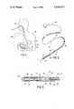
- FIG. 1is a schematic view of the feeding tube of the instant invention installed in a patient
- FIG. 2is a perspective view of the feeding tube
- FIG. 3is an enlarged sectional view taken along line 3--3 in FIG. 2.
- the feeding tube 10comprises an elongated tubular shaft portion generally indicated at 12 having distal and proximal ends 14 and 16, respectively, an enlarged intermediate portion generally indicated at 18 which extends from the distal end 14 of the shaft 12, and a weighted bolus generally indicated at 20 which extends from the intermediate portion 18.
- the feeding tube 10is adapted to be installed or intubated into a patient 22 so that it extends through the nasal pharynx 24, through the esophagus 26, into the stomach 28, and sometimes into the jejunum area 30 of the intestines of the patient which is just past the pyloric valve (not shown). Accordingly, the feeding tube 10 can be effectively utilized for introducing a feeding formula into the stomach 28 or the jejunum area 30, depending on the manner in which the tube has been installed, to provide nutritional feeding of the patient 22 over a prolonged period of time.
- the tubular shaft 12comprises an elongated tubular member having an imperforate outer wall 32 and a lumen 34 extends longitudinally through the shaft 12.
- the shaft 12is constructed so that it has sufficient flexibility to permit the passage thereof through a nostril of a patient during the intubation of the tube 10 in the patient, but so that it nevertheless has sufficient rigidity to permit the intubation of the tube without the use of a stylet in the lumen 34.
- the shaft 12is preferably constructed of a material having an A Durometer Scale hardness of between 45 and 90, and it preferably has a cross-sectional dimension of between 0.080 and 0.160 inches.
- the shaft 12is preferably constructed so that the thickness of the wall 32 is between 0.015 and 0.035 inches and so that the lumen 34 has a sectional dimension of at least 0.05 inches.
- the shaftis constructed of a polyether based polyurethane so that it is substantially unaffected by gastric mucosa in the stomach of the patient, even when the tube 10 is left in the patient for a period of up to a month.
- the intermediate portion 18is received and secured on the distal end 14 of the shaft 12, and it is constructed with an enlarged sectional dimension with respect to the shaft 12.
- the intermediate portion 18is formed with a socket 36 therein and the distal end portion of the shaft 12 is received in the socket 36 and secured therein with a suitable adhesive.
- the shaft 12 and the intermediate portion 18are integrally formed are also contemplated.
- the intermediate portion 18is formed with a transverse slot 38 therein which communicates with the lumen 34 and defines an inner passage and a pair of side apertures in the intermediate portion for passing feeding formula from the lumen 34 to the exterior of the tube 10.
- the cross-sectional area of the slot 38is preferably at least as great as the cross-sectional area of the lumen 34 to permit the unrestricted flow of feeding formula from the lumen 34 through the slot 38.
- the portion of the interior passage in the intermediate portion 18 which is closest to the bolus 20is adjacent the portions of the apertures defined by the slot 38 which are closest to the bolus 20 so that a dead space is not formed in the interior of the intermediate portion 18.
- the intermediate portion 18is preferably constructed so that it is at least as rigid as the shaft 12 and it is constructed so that it is sufficiently flexible to permit the passage thereof through a nostril of a patient during the installation of the tube 10 in the patient, but nevertheless sufficiently rigid to permit the installation of the tube 10 in the patient without the use of the stylet.
- the intermediate portion 18is constructed of a polyether based polyurethane having an A Durometer Scale hardness of between 50 and 100.
- the intermediate portion 18has an enlarged sectional dimension with respect to the shaft 12 to make it resistant to collapsing or kinking, although it obviously must be dimensioned to be passed through a nostril of a patient.
- the end of the intermediate portion 18, which is opposite from the shaft 12,is formed as a cylindrical plug 40 for receiving the bolus 20, the plug 40 having an axial bore 42 of reduced extent therein for providing increased flexibility in the intermediate portion 18 and for facilitating the manufacture thereof by molding.
- the bolus 20comprises an outer casing portion 44 and a plurality of weight elements 46 which are received and contained in the casing portion 44.
- the casing portion 44is preferably made of a polyether based polyurethane, and it preferably has substantially the same cross-sectional dimension as the intermediate portion 18.
- the casing portion 44is preferably received and secured on the plug portion 40 of the intermediate portion 18 with a suitable adhesive and it preferably forms a generally smooth extension of the intermediate portion 18.
- a substantially axial bore 48is provided in the casing portion 44 for receiving and containing the weight elements 46 and the casing portion 44 preferably terminates in a substantially rounded end 50.
- the weight elements 46are preferably made of a suitable corrosion resistant non toxic metal, such as stainless steel, so that they would not cause significant injury to a patient in the event of a rupture in the casing portion 44. Further, the weight elements 46 are preferably formed with rounded ends 52 so that they do not bind on each other when the bolus 20 is flexed or bent, and they are preferably formed in reduced lengths so that they do not substantially restrict the flexibility of the bolus 20.
- the casing portion 44 of the bolus 20is preferably made of a material having an A Durometer Scale hardness of between 45 and 90, and it is preferably made of a polyether based polyurethane. Further, although in the tube 10 as herein set forth, the bolus 20 and the intermediate portion 18 are formed as separate components, other embodiments of the feeding tube of the instant invention wherein the bolus and the intermediate portion are integrally formed are contemplated.
- the tube 10For use of the tube 10, it is installed in a patient, such as the patient 22, in the manner hereinabove set forth. In this regard, however, because the side wall 32 is imperforate, and because the tube 10 has a somewhat higher degree of rigidity than the heretofore known feeding tubes, the tube 10 can be installed in the patient 22 without the use of a stylet in the lumen 34. In this regard, since the tube 10 is constructed of a polyether based polyurethane, the hardness or stiffness of the tube 10 is not increased significantly by prolonged exposure to gastric mucosa and therefore the tube can be constructed with a slightly higher degree of stiffness without significantly affecting the ultimate patient comfort.
- the intermediate portion 18also does not tend to kink or collapse when the tube 10 is installed without the use of a stylet. Further, because the slot 38 also defines the end of the open interior portion of the tube 10, the tube 10 does not have an interior area of "dead space" where feeding formula could collect or solidify, and because the area of the apertures defined by the slot 38 is at least as great as the sectional area of the lumen 34, the slot 38 provides little or no resistance to the flow of feeding formula through the tube 10.
- the feeding tube of the instant inventionhas substantial advantages over the heretofore known feeding tubes.
- the feeding tube 10can be intubated in a patient without the use of a stylet, and hence, it can be intubated with substantially less risk to the patient.
- the feeding tubeis constructed so that it can be effectively installed in a patient, without causing substantial trauma to the patient and it can remain in the patient for a prolonged period of time without causing irritation.
- the feeding tube of the instant inventionrepresents a significant advancement in the medical art which has substantial merit from both medical and commercial standpoints.
Landscapes
- Health & Medical Sciences (AREA)
- Life Sciences & Earth Sciences (AREA)
- Animal Behavior & Ethology (AREA)
- General Health & Medical Sciences (AREA)
- Public Health (AREA)
- Veterinary Medicine (AREA)
- Otolaryngology (AREA)
- Pulmonology (AREA)
- Materials For Medical Uses (AREA)
Abstract
Description
Claims (6)
Priority Applications (1)
| Application Number | Priority Date | Filing Date | Title |
|---|---|---|---|
| US06/703,319US4610673A (en) | 1985-02-19 | 1985-02-19 | Gastroenteric feeding tube |
Applications Claiming Priority (1)
| Application Number | Priority Date | Filing Date | Title |
|---|---|---|---|
| US06/703,319US4610673A (en) | 1985-02-19 | 1985-02-19 | Gastroenteric feeding tube |
Publications (1)
| Publication Number | Publication Date |
|---|---|
| US4610673Atrue US4610673A (en) | 1986-09-09 |
Family
ID=24824923
Family Applications (1)
| Application Number | Title | Priority Date | Filing Date |
|---|---|---|---|
| US06/703,319Expired - LifetimeUS4610673A (en) | 1985-02-19 | 1985-02-19 | Gastroenteric feeding tube |
Country Status (1)
| Country | Link |
|---|---|
| US (1) | US4610673A (en) |
Cited By (16)
| Publication number | Priority date | Publication date | Assignee | Title |
|---|---|---|---|---|
| US4778455A (en)* | 1985-02-14 | 1988-10-18 | Terumo Kabushiki Kaisha | Catheter |
| US4781704A (en)* | 1987-02-24 | 1988-11-01 | Entech, Inc. | Feeding tube assembly with collapsible outlet connector |
| US5057091A (en)* | 1989-07-31 | 1991-10-15 | Corpak, Inc. | Enteral feeding tube with a flexible bolus and feeding bolus |
| US5242389A (en)* | 1990-07-19 | 1993-09-07 | Sherwood Medical Company | Enteral feeding tube enteral feeding tube with separate stylet lumen |
| US5565255A (en)* | 1994-08-29 | 1996-10-15 | The Procter And Gamble Company | Sheet material having a fibrous surface and method of making same |
| US20030225369A1 (en)* | 2002-05-31 | 2003-12-04 | Kimberly-Clark Worldwide, Inc. | Low profile transpyloric jejunostomy system |
| US20030225392A1 (en)* | 2002-05-31 | 2003-12-04 | Kimberly-Clark Worldwide, Inc. | Low profile transpyloric jejunostomy system and method to enable |
| US20030225393A1 (en)* | 2002-05-31 | 2003-12-04 | Kimberly-Clark Worldwide, Inc. | Low profile transpyloric jejunostomy system and method to enable |
| US7066914B2 (en) | 2000-07-12 | 2006-06-27 | Bird Products Corporation | Catheter having a tip with an elongated collar |
| US20070083084A1 (en)* | 2003-12-12 | 2007-04-12 | Japan Science And Technology Agency | Active tube and active tube system |
| USD561329S1 (en) | 2006-10-04 | 2008-02-05 | Kimberly-Clark Worldwide, Inc. | Low profile transpyloric jejunostomy catheter |
| US7976518B2 (en) | 2005-01-13 | 2011-07-12 | Corpak Medsystems, Inc. | Tubing assembly and signal generator placement control device and method for use with catheter guidance systems |
| US8685918B1 (en) | 2011-01-05 | 2014-04-01 | Marco Gasparotti | Weight loss regimen comprising enteral and oral feeding segments effective for the treatment of obesity |
| US9028441B2 (en) | 2011-09-08 | 2015-05-12 | Corpak Medsystems, Inc. | Apparatus and method used with guidance system for feeding and suctioning |
| US9597263B2 (en) | 2013-03-15 | 2017-03-21 | Nadarasa Visveshwara | Fluid and nutrition delivery device and method of use |
| WO2018232190A1 (en)* | 2017-06-14 | 2018-12-20 | The University Of Vermont And State Agricultural College | Peritoneal dialysis (pd) catheter weighted anchor |
Citations (6)
| Publication number | Priority date | Publication date | Assignee | Title |
|---|---|---|---|---|
| US1736182A (en)* | 1927-12-12 | 1929-11-19 | James A Wilkins | Stomach tube |
| US4249535A (en)* | 1979-02-02 | 1981-02-10 | Hargest Thomas S Iii | Gastric feeding device |
| US4390017A (en)* | 1981-08-07 | 1983-06-28 | Harrison Eugene O | Enteral feeding system |
| US4410320A (en)* | 1981-08-28 | 1983-10-18 | Ethox Corp. | Weighted enteric feeding tube |
| US4516970A (en)* | 1982-09-13 | 1985-05-14 | Kaufman Jack W | Medical device |
| US4547192A (en)* | 1982-11-12 | 1985-10-15 | Superior Plastic Products Corp. | Gastroenteric feeding tube |
- 1985
- 1985-02-19USUS06/703,319patent/US4610673A/ennot_activeExpired - Lifetime
Patent Citations (6)
| Publication number | Priority date | Publication date | Assignee | Title |
|---|---|---|---|---|
| US1736182A (en)* | 1927-12-12 | 1929-11-19 | James A Wilkins | Stomach tube |
| US4249535A (en)* | 1979-02-02 | 1981-02-10 | Hargest Thomas S Iii | Gastric feeding device |
| US4390017A (en)* | 1981-08-07 | 1983-06-28 | Harrison Eugene O | Enteral feeding system |
| US4410320A (en)* | 1981-08-28 | 1983-10-18 | Ethox Corp. | Weighted enteric feeding tube |
| US4516970A (en)* | 1982-09-13 | 1985-05-14 | Kaufman Jack W | Medical device |
| US4547192A (en)* | 1982-11-12 | 1985-10-15 | Superior Plastic Products Corp. | Gastroenteric feeding tube |
Non-Patent Citations (4)
| Title |
|---|
| Saltzberg et al., "Feeding Tube-Induced Pneumothorax", in Journal of Parenteral and Enteral Nutrition, vol. 8, No. 6, 1984, pp. 714-716. |
| Saltzberg et al., Feeding Tube Induced Pneumothorax , in Journal of Parenteral and Enteral Nutrition, vol. 8, No. 6, 1984, pp. 714 716.* |
| Valentine et al., "Pleural Complications of Nasoenteric Feeding Tubes", in Journal of Parenteral and Enteral Nutrition, vol. 9, No. 5, 1985, pp. 605-607. |
| Valentine et al., Pleural Complications of Nasoenteric Feeding Tubes , in Journal of Parenteral and Enteral Nutrition, vol. 9, No. 5, 1985, pp. 605 607.* |
Cited By (23)
| Publication number | Priority date | Publication date | Assignee | Title |
|---|---|---|---|---|
| US4778455A (en)* | 1985-02-14 | 1988-10-18 | Terumo Kabushiki Kaisha | Catheter |
| US4781704A (en)* | 1987-02-24 | 1988-11-01 | Entech, Inc. | Feeding tube assembly with collapsible outlet connector |
| US5057091A (en)* | 1989-07-31 | 1991-10-15 | Corpak, Inc. | Enteral feeding tube with a flexible bolus and feeding bolus |
| US5242389A (en)* | 1990-07-19 | 1993-09-07 | Sherwood Medical Company | Enteral feeding tube enteral feeding tube with separate stylet lumen |
| US5565255A (en)* | 1994-08-29 | 1996-10-15 | The Procter And Gamble Company | Sheet material having a fibrous surface and method of making same |
| US5618583A (en)* | 1994-08-29 | 1997-04-08 | The Procter & Gamble Company | Sheet material having a fibrous surface and method of making the same |
| US6136405A (en)* | 1994-08-29 | 2000-10-24 | The Procter & Gamble Company | Sheet material having a fibrous surface and method of making the same |
| US7066914B2 (en) | 2000-07-12 | 2006-06-27 | Bird Products Corporation | Catheter having a tip with an elongated collar |
| US20030225392A1 (en)* | 2002-05-31 | 2003-12-04 | Kimberly-Clark Worldwide, Inc. | Low profile transpyloric jejunostomy system and method to enable |
| US20030225393A1 (en)* | 2002-05-31 | 2003-12-04 | Kimberly-Clark Worldwide, Inc. | Low profile transpyloric jejunostomy system and method to enable |
| US20030225369A1 (en)* | 2002-05-31 | 2003-12-04 | Kimberly-Clark Worldwide, Inc. | Low profile transpyloric jejunostomy system |
| US20070083084A1 (en)* | 2003-12-12 | 2007-04-12 | Japan Science And Technology Agency | Active tube and active tube system |
| US9579488B2 (en) | 2005-01-13 | 2017-02-28 | Corpak Medsystems, Inc. | Tubing assembly and signal generator placement control device and method for use with catheter guidance systems |
| US7976518B2 (en) | 2005-01-13 | 2011-07-12 | Corpak Medsystems, Inc. | Tubing assembly and signal generator placement control device and method for use with catheter guidance systems |
| US9131956B2 (en) | 2005-01-13 | 2015-09-15 | Corpak Medsystems, Inc. | Tubing assembly and signal generator placement control device and method for use with catheter guidance systems |
| US9889277B2 (en) | 2005-01-13 | 2018-02-13 | Avent, Inc. | Tubing assembly and signal generator placement control device and method for use with catheter guidance systems |
| US10549074B2 (en) | 2005-01-13 | 2020-02-04 | Avent, Inc. | Tubing assembly and signal generation placement device and method for use with catheter guidance systems |
| USD561329S1 (en) | 2006-10-04 | 2008-02-05 | Kimberly-Clark Worldwide, Inc. | Low profile transpyloric jejunostomy catheter |
| US8685918B1 (en) | 2011-01-05 | 2014-04-01 | Marco Gasparotti | Weight loss regimen comprising enteral and oral feeding segments effective for the treatment of obesity |
| US9028441B2 (en) | 2011-09-08 | 2015-05-12 | Corpak Medsystems, Inc. | Apparatus and method used with guidance system for feeding and suctioning |
| US9918907B2 (en) | 2011-09-08 | 2018-03-20 | Avent, Inc. | Method for electromagnetic guidance of feeding and suctioning tube assembly |
| US9597263B2 (en) | 2013-03-15 | 2017-03-21 | Nadarasa Visveshwara | Fluid and nutrition delivery device and method of use |
| WO2018232190A1 (en)* | 2017-06-14 | 2018-12-20 | The University Of Vermont And State Agricultural College | Peritoneal dialysis (pd) catheter weighted anchor |
Similar Documents
| Publication | Publication Date | Title |
|---|---|---|
| US4610673A (en) | Gastroenteric feeding tube | |
| US4410320A (en) | Weighted enteric feeding tube | |
| EP0219506B1 (en) | Non-occluding high flow enteral feeding tube | |
| US3880168A (en) | Endotracheal tube | |
| US4547192A (en) | Gastroenteric feeding tube | |
| US5334167A (en) | Modified nasogastric tube for use in enteral feeding | |
| US5242389A (en) | Enteral feeding tube enteral feeding tube with separate stylet lumen | |
| US4769014A (en) | Gastroenteric feeding tube for endoscopic placement | |
| EP1295586B1 (en) | Corporeal access tube assembly | |
| EP1557192B1 (en) | Catheter assembly with two stylets | |
| US4249535A (en) | Gastric feeding device | |
| US8409169B1 (en) | Catheter and method of making the same | |
| JP5214731B2 (en) | Gastroesophageal reflux control system and pump | |
| US5860960A (en) | Bolster for corporeal access tube assembly | |
| US4496347A (en) | Feeding tube stylet | |
| US4781704A (en) | Feeding tube assembly with collapsible outlet connector | |
| RU2179461C2 (en) | Catheter device for making connection to small intestine for supplying liquids | |
| US5643230A (en) | Nasogastric suction catheter | |
| US5697365A (en) | Endotracheal tube construction and method for intubating a patient | |
| EP0920881A2 (en) | Catheter assemblies and inner cannulae | |
| JP3740016B2 (en) | Bolster for body access tube assembly | |
| US20150122251A1 (en) | Kink resistant intubation device | |
| US4490143A (en) | Feeding tube assembly | |
| EP1409061A4 (en) | Catheter and stylet assembly and method of catheter insertion | |
| US20050171468A1 (en) | Gastric aspirate intestinal feeding tube |
Legal Events
| Date | Code | Title | Description |
|---|---|---|---|
| AS | Assignment | Owner name:SUPERIOR PLASTICS PRODUCTS CORP., CUMBERLAND INDUS Free format text:ASSIGNMENT OF ASSIGNORS INTEREST.;ASSIGNOR:RUSSO, RONALD D.;REEL/FRAME:004372/0903 Effective date:19850211 | |
| AS | Assignment | Owner name:SUPERIOR HEALTHCARE GROUP, INC. Free format text:CHANGE OF NAME;ASSIGNOR:SUPERIOR PLASTICS, INC., (CHANGED TO SUPERIOR PLASTIC PRODUCTS CO.,;REEL/FRAME:004486/0796 Effective date:19850121 | |
| AS | Assignment | Owner name:RHODE ISLAND HOSPITAL TRUST NATIONAL BANK, ONE HOS Free format text:SECURITY INTEREST;ASSIGNOR:SUPERIOR HEALTHCARE GROUP, INC., A CORP OF RI.;REEL/FRAME:004533/0563 Effective date:19860320 | |
| STCF | Information on status: patent grant | Free format text:PATENTED CASE | |
| FEPP | Fee payment procedure | Free format text:PAYOR NUMBER ASSIGNED (ORIGINAL EVENT CODE: ASPN); ENTITY STATUS OF PATENT OWNER: LARGE ENTITY | |
| AS | Assignment | Owner name:RHODE ISLAND HOSPITAL TRUST NATIONAL BANK, ONE HOS Free format text:SECURITY INTEREST;ASSIGNOR:SUPERIOR HEALTHCARE GROUP, INC.,;REEL/FRAME:004920/0729 Effective date:19880527 | |
| FPAY | Fee payment | Year of fee payment:4 | |
| AS | Assignment | Owner name:SUPERIOR BIOSYSTEMS INC., CUMBERLAND INDUSTRIAL PA Free format text:ASSIGNMENT OF ASSIGNORS INTEREST.;ASSIGNOR:SUPERIOR HEALTHCARE GROUP, INC.;REEL/FRAME:005140/0781 Effective date:19890830 | |
| AS | Assignment | Owner name:SANDOZ NUTRITION CORPORATION, MINNESOTA Free format text:ASSIGNMENT OF ASSIGNORS INTEREST.;ASSIGNOR:SUPERIOR BISYSTEMS INC.;REEL/FRAME:005228/0949 Effective date:19891221 | |
| AS | Assignment | Owner name:SUPERIOR HEALTHCARE GROUP, INC., A CORP. OF RI., R Free format text:RELEASED BY SECURED PARTY;ASSIGNOR:RHODE ISLAND HOSPITAL TRUST NATIONAL BANK, ONE HOSPITAL TRUST PLAZA, PROVIDENCE, RI. 02903, A NATIONAL BANKING ASSOCIATION;REEL/FRAME:005232/0799 Effective date:19891221 Owner name:SUPERIOR HEALTHCARE GROUP, INC., A CORP. OF RI., R Free format text:RELEASED BY SECURED PARTY;ASSIGNOR:RHODE ISLAND HOSPITAL TRUST NATIONAL BANK, ONE HOSPITAL TRUST PLAZA, PROVIDENCE, RI. 02903, A NATIONAL BANKING ASSOCIATION;REEL/FRAME:005232/0796 Effective date:19891221 | |
| AS | Assignment | Owner name:MUSKIN LEISURE PRODUCTS, INC. A DE CORPORATION, Free format text:RELEASED BY SECURED PARTY;ASSIGNOR:MUSKIN, INC., A CORPORATION OF NV;REEL/FRAME:005909/0175 Effective date:19911029 | |
| AS | Assignment | Owner name:SUPERIOR HEALTHCARE GROUP, INC. A RI CORPORATION Free format text:NUNC PRO TUNC ASSIGNMENT;ASSIGNOR:RHODE ISLAND HOSPITAL TRUST NATIONAL BANK;REEL/FRAME:005962/0129 Effective date:19910917 | |
| FEPP | Fee payment procedure | Free format text:PAT HLDR NO LONGER CLAIMS SMALL ENT STAT AS SMALL BUSINESS (ORIGINAL EVENT CODE: LSM2); ENTITY STATUS OF PATENT OWNER: LARGE ENTITY | |
| FEPP | Fee payment procedure | Free format text:PAYER NUMBER DE-ASSIGNED (ORIGINAL EVENT CODE: RMPN); ENTITY STATUS OF PATENT OWNER: LARGE ENTITY Free format text:PAYOR NUMBER ASSIGNED (ORIGINAL EVENT CODE: ASPN); ENTITY STATUS OF PATENT OWNER: LARGE ENTITY | |
| FPAY | Fee payment | Year of fee payment:8 | |
| FPAY | Fee payment | Year of fee payment:12 | |
| AS | Assignment | Owner name:NOVARTIS NUTRITION AG, SWITZERLAND Free format text:CHANGE OF NAME;ASSIGNOR:SANDOZ NUTRITION LTD.;REEL/FRAME:011204/0124 Effective date:19970407 |