US4610658A - Automated peritoneovenous shunt - Google Patents
Automated peritoneovenous shuntDownload PDFInfo
- Publication number
- US4610658A US4610658AUS06/703,758US70375885AUS4610658AUS 4610658 AUS4610658 AUS 4610658AUS 70375885 AUS70375885 AUS 70375885AUS 4610658 AUS4610658 AUS 4610658A
- Authority
- US
- United States
- Prior art keywords
- chamber
- pump
- housing
- shunt system
- valve
- Prior art date
- Legal status (The legal status is an assumption and is not a legal conclusion. Google has not performed a legal analysis and makes no representation as to the accuracy of the status listed.)
- Expired - Lifetime
Links
- 239000012530fluidSubstances0.000claimsabstractdescription42
- 230000000151anti-reflux effectEffects0.000claimsabstractdescription18
- 238000006073displacement reactionMethods0.000claimsabstractdescription16
- 230000001453nonthrombogenic effectEffects0.000claimsabstractdescription3
- 238000005086pumpingMethods0.000claimsdescription8
- 239000007788liquidSubstances0.000claimsdescription5
- 238000007789sealingMethods0.000claimsdescription5
- 230000007246mechanismEffects0.000claimsdescription4
- 230000036760body temperatureEffects0.000claimsdescription2
- 230000001050lubricating effectEffects0.000claimsdescription2
- 239000012808vapor phaseSubstances0.000claimsdescription2
- 206010003445AscitesDiseases0.000abstractdescription12
- 238000012546transferMethods0.000abstractdescription6
- 210000004303peritoneumAnatomy0.000abstractdescription5
- 210000003200peritoneal cavityAnatomy0.000abstractdescription4
- 238000009825accumulationMethods0.000abstractdescription3
- 210000000748cardiovascular systemAnatomy0.000abstract1
- 239000000463materialSubstances0.000description8
- 210000001124body fluidAnatomy0.000description6
- 239000010839body fluidSubstances0.000description6
- 239000004945silicone rubberSubstances0.000description6
- 229920002379silicone rubberPolymers0.000description5
- 238000011144upstream manufacturingMethods0.000description4
- 230000002792vascularEffects0.000description4
- 230000036772blood pressureEffects0.000description3
- 238000013461designMethods0.000description3
- -1tetramethylcyleneChemical compound0.000description3
- 238000002560therapeutic procedureMethods0.000description3
- 210000005166vasculatureAnatomy0.000description3
- RTZKZFJDLAIYFH-UHFFFAOYSA-NDiethyl etherChemical compoundCCOCCRTZKZFJDLAIYFH-UHFFFAOYSA-N0.000description2
- 239000004809TeflonSubstances0.000description2
- 229920006362Teflon®Polymers0.000description2
- 229910000828alnicoInorganic materials0.000description2
- 210000003567ascitic fluidAnatomy0.000description2
- 230000008901benefitEffects0.000description2
- 239000000560biocompatible materialSubstances0.000description2
- 210000004204blood vesselAnatomy0.000description2
- 230000006835compressionEffects0.000description2
- 238000007906compressionMethods0.000description2
- 230000006870functionEffects0.000description2
- TZIHFWKZFHZASV-UHFFFAOYSA-Nmethyl formateChemical compoundCOC=OTZIHFWKZFHZASV-UHFFFAOYSA-N0.000description2
- 238000012986modificationMethods0.000description2
- 230000004048modificationEffects0.000description2
- 229920001343polytetrafluoroethylenePolymers0.000description2
- 230000001953sensory effectEffects0.000description2
- 239000010935stainless steelSubstances0.000description2
- 229910001220stainless steelInorganic materials0.000description2
- 238000001356surgical procedureMethods0.000description2
- 210000001519tissueAnatomy0.000description2
- CDFSOKHNACTNPU-GHUQRRHWSA-N3-[(1r,3s,5s,8r,9s,10s,11r,13r,17r)-1,5,11,14-tetrahydroxy-10,13-dimethyl-3-[(2r,3r,4r,5s,6s)-3,4,5-trihydroxy-6-methyloxan-2-yl]oxy-2,3,4,6,7,8,9,11,12,15,16,17-dodecahydro-1h-cyclopenta[a]phenanthren-17-yl]-2h-furan-5-oneChemical compoundO[C@@H]1[C@H](O)[C@H](O)[C@H](C)O[C@H]1O[C@@H]1C[C@@]2(O)CC[C@H]3C4(O)CC[C@H](C=5COC(=O)C=5)[C@@]4(C)C[C@@H](O)[C@@H]3[C@@]2(C)[C@H](O)C1CDFSOKHNACTNPU-GHUQRRHWSA-N0.000description1
- 206010060954Abdominal HerniaDiseases0.000description1
- 206010053567CoagulopathiesDiseases0.000description1
- 229910000881Cu alloyInorganic materials0.000description1
- 102000009123FibrinHuman genes0.000description1
- 108010073385FibrinProteins0.000description1
- BWGVNKXGVNDBDI-UHFFFAOYSA-NFibrin monomerChemical compoundCNC(=O)CNC(=O)CNBWGVNKXGVNDBDI-UHFFFAOYSA-N0.000description1
- 206010020772HypertensionDiseases0.000description1
- 208000001647Renal InsufficiencyDiseases0.000description1
- 208000004756Respiratory InsufficiencyDiseases0.000description1
- 108010023197StreptokinaseProteins0.000description1
- RTAQQCXQSZGOHL-UHFFFAOYSA-NTitaniumChemical compound[Ti]RTAQQCXQSZGOHL-UHFFFAOYSA-N0.000description1
- 208000019790abdominal distentionDiseases0.000description1
- 238000010521absorption reactionMethods0.000description1
- 230000001154acute effectEffects0.000description1
- 239000000853adhesiveSubstances0.000description1
- 230000001070adhesive effectEffects0.000description1
- 239000000956alloySubstances0.000description1
- 208000015294blood coagulation diseaseDiseases0.000description1
- 210000004556brainAnatomy0.000description1
- 239000011248coating agentSubstances0.000description1
- 238000000576coating methodMethods0.000description1
- KPLQYGBQNPPQGA-UHFFFAOYSA-Ncobalt samariumChemical compound[Co].[Sm]KPLQYGBQNPPQGA-UHFFFAOYSA-N0.000description1
- 230000008878couplingEffects0.000description1
- 238000010168coupling processMethods0.000description1
- 238000005859coupling reactionMethods0.000description1
- 230000007547defectEffects0.000description1
- 230000000593degrading effectEffects0.000description1
- 230000001419dependent effectEffects0.000description1
- 229940079593drugDrugs0.000description1
- 239000003814drugSubstances0.000description1
- 229950003499fibrinDrugs0.000description1
- 230000004907fluxEffects0.000description1
- 208000021302gastroesophageal reflux diseaseDiseases0.000description1
- 150000008282halocarbonsChemical class0.000description1
- 230000002440hepatic effectEffects0.000description1
- 208000003906hydrocephalusDiseases0.000description1
- 238000002513implantationMethods0.000description1
- 208000015181infectious diseaseDiseases0.000description1
- 238000001802infusionMethods0.000description1
- 238000002347injectionMethods0.000description1
- 239000007924injectionSubstances0.000description1
- 238000007912intraperitoneal administrationMethods0.000description1
- 210000004731jugular veinAnatomy0.000description1
- 201000006370kidney failureDiseases0.000description1
- 210000004185liverAnatomy0.000description1
- 208000019423liver diseaseDiseases0.000description1
- 230000001926lymphatic effectEffects0.000description1
- 229910001004magnetic alloyInorganic materials0.000description1
- 238000012423maintenanceMethods0.000description1
- 238000007726management methodMethods0.000description1
- 229920002529medical grade siliconePolymers0.000description1
- 231100000252nontoxicToxicity0.000description1
- 230000003000nontoxic effectEffects0.000description1
- 208000000689peptic esophagitisDiseases0.000description1
- 230000000737periodic effectEffects0.000description1
- 239000004033plasticSubstances0.000description1
- 239000004810polytetrafluoroethyleneSubstances0.000description1
- 108090000623proteins and genesProteins0.000description1
- 102000004169proteins and genesHuman genes0.000description1
- 229910052761rare earth metalInorganic materials0.000description1
- 150000002910rare earth metalsChemical class0.000description1
- 239000011347resinSubstances0.000description1
- 229920005989resinPolymers0.000description1
- 239000012260resinous materialSubstances0.000description1
- 201000004193respiratory failureDiseases0.000description1
- 230000004044responseEffects0.000description1
- 238000012552reviewMethods0.000description1
- 210000005245right atriumAnatomy0.000description1
- 229910000938samarium–cobalt magnetInorganic materials0.000description1
- 229920000260silasticPolymers0.000description1
- 229960005202streptokinaseDrugs0.000description1
- 238000007920subcutaneous administrationMethods0.000description1
- 230000009885systemic effectEffects0.000description1
- 229910052715tantalumInorganic materials0.000description1
- GUVRBAGPIYLISA-UHFFFAOYSA-Ntantalum atomChemical compound[Ta]GUVRBAGPIYLISA-UHFFFAOYSA-N0.000description1
- BFKJFAAPBSQJPD-UHFFFAOYSA-NtetrafluoroetheneChemical groupFC(F)=C(F)FBFKJFAAPBSQJPD-UHFFFAOYSA-N0.000description1
- 239000010936titaniumSubstances0.000description1
- 229910052719titaniumInorganic materials0.000description1
- 210000003462veinAnatomy0.000description1
- 230000002861ventricularEffects0.000description1
Images
Classifications
- A—HUMAN NECESSITIES
- A61—MEDICAL OR VETERINARY SCIENCE; HYGIENE
- A61M—DEVICES FOR INTRODUCING MEDIA INTO, OR ONTO, THE BODY; DEVICES FOR TRANSDUCING BODY MEDIA OR FOR TAKING MEDIA FROM THE BODY; DEVICES FOR PRODUCING OR ENDING SLEEP OR STUPOR
- A61M27/00—Drainage appliance for wounds or the like, i.e. wound drains, implanted drains
- A61M27/002—Implant devices for drainage of body fluids from one part of the body to another
- A61M27/006—Cerebrospinal drainage; Accessories therefor, e.g. valves
- A—HUMAN NECESSITIES
- A61—MEDICAL OR VETERINARY SCIENCE; HYGIENE
- A61M—DEVICES FOR INTRODUCING MEDIA INTO, OR ONTO, THE BODY; DEVICES FOR TRANSDUCING BODY MEDIA OR FOR TAKING MEDIA FROM THE BODY; DEVICES FOR PRODUCING OR ENDING SLEEP OR STUPOR
- A61M27/00—Drainage appliance for wounds or the like, i.e. wound drains, implanted drains
- A61M27/002—Implant devices for drainage of body fluids from one part of the body to another
- A—HUMAN NECESSITIES
- A61—MEDICAL OR VETERINARY SCIENCE; HYGIENE
- A61M—DEVICES FOR INTRODUCING MEDIA INTO, OR ONTO, THE BODY; DEVICES FOR TRANSDUCING BODY MEDIA OR FOR TAKING MEDIA FROM THE BODY; DEVICES FOR PRODUCING OR ENDING SLEEP OR STUPOR
- A61M1/00—Suction or pumping devices for medical purposes; Devices for carrying-off, for treatment of, or for carrying-over, body-liquids; Drainage systems
- A61M1/80—Suction pumps
- A—HUMAN NECESSITIES
- A61—MEDICAL OR VETERINARY SCIENCE; HYGIENE
- A61M—DEVICES FOR INTRODUCING MEDIA INTO, OR ONTO, THE BODY; DEVICES FOR TRANSDUCING BODY MEDIA OR FOR TAKING MEDIA FROM THE BODY; DEVICES FOR PRODUCING OR ENDING SLEEP OR STUPOR
- A61M2205/00—General characteristics of the apparatus
- A61M2205/82—Internal energy supply devices
- A61M2205/8206—Internal energy supply devices battery-operated
- A—HUMAN NECESSITIES
- A61—MEDICAL OR VETERINARY SCIENCE; HYGIENE
- A61M—DEVICES FOR INTRODUCING MEDIA INTO, OR ONTO, THE BODY; DEVICES FOR TRANSDUCING BODY MEDIA OR FOR TAKING MEDIA FROM THE BODY; DEVICES FOR PRODUCING OR ENDING SLEEP OR STUPOR
- A61M39/00—Tubes, tube connectors, tube couplings, valves, access sites or the like, specially adapted for medical use
- A61M39/02—Access sites
- A61M39/0208—Subcutaneous access sites for injecting or removing fluids
Definitions
- This inventionrelates to an implantable anti-reflux fluid displacement peritoneovenous shunt used to transfer an unwanted accumulation of body fluids from a body cavity to a site where they can be processed by the body.
- the primary use for the shuntis in the treatment of patients with ascites by the displacement of accumulated peritoneal cavity fluid into the systemic venous circulation.
- the device of the aforesaid applicationis a peritoneovenous shunt in which ascites fluid is transferred from the peritoneum to the vasculature via a manually operated compression pump. That device is not an alternative for certain patients who require peritoneovenous shunting but for a variety of reasons are unable to perform the pumping mechanics.
- the present inventionis directed to a peritoneovenous shunt which features automation of the earlier design, thus expanding the benefit of this therapy to a broader population of patients and providing greater convenience to existing patients.
- the shunt of this inventioncan, with modest modifications, be utilized for the transfer of other body fluids, e.g., the displacment of brain ventricular fluid in hydrocephalus to either the right atrium of the heart or to the peritoneal cavity.
- other body fluidse.g., the displacment of brain ventricular fluid in hydrocephalus to either the right atrium of the heart or to the peritoneal cavity.
- the implantable anti-reflux fluid displacement peritoneovenous shuntconsists of three parts, connected by flexible tubing: (1) a double chambered multi-micro-orifice collecting device; (2) an anti-reflux, anti-backdiffusion magnetically driven fluid pump having at least one variable volume chamber; and (3) an anti-reflux, anti-backdiffusion, non-thrombogenic catheter for intravascular placement.
- the fluid pumpmay be of either the reciprocating diaphragm or piston variety. It includes an internal magnetic armature which is free to move within a housing and which is transcutaneously magnetically coupled to an external driver during fluid transfer. The movement of the internal magnet is defined by the corresponding movement of the external driver magnet to which it is coupled.
- the fluid pumpmay be rotary driven from an external rotary source magnetically coupled to a bellows displacement pump operated by an internal coupled magnetic screw jack.
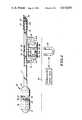
- FIG. 1is an elevational view of one form of peritoneovenous shunt according to the present invention, with portions shown partly broken away and in section to reveal structural details;
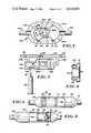
- FIG. 2is an elevation in section of a slightly modified form of diaphragm pump
- FIG. 3is an elevation, partly broken away and in section, showing a further modified form of diaphragm pump
- FIG. 4is an elevation, partly broken away and in section, showing a form of spool piston pump in pumping mode
- FIG. 5is a similar elevation, partly broken away and in section, of a spool piston pump in its return mode
- FIG. 6is a fragmentary vertical section showing a form of spool piston flap valve
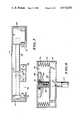
- FIG. 7is an elevation partly in section showing a form of low speed drive for a magnetic actuator
- FIG. 8is an elevation in section of a rotating armature bellows pump.
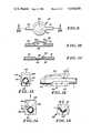
- FIG. 9is a top plan view of one form of transcutaneously actuated valve
- FIG. 10is a section on the line 10--10 of FIG. 9 and in the direction of the arrows showing the valve in open position;
- FIG. 11is a similar section showing the valve in closed position
- FIG. 12is a side elevational view of another form of transcutaneously actuated valve
- FIG. 13is a left end elevational view thereof
- FIG. 14is a right end elevational view thereof showing the valve in open position
- FIG. 15is a similar end elevational view showing the valve in closed position.
- the peritoneovenous shuntincludes a sieve-like elongated collecting device 10 connected by a catheter or similar length of flexible tubing 11 to a check valve catheter tip 12.
- a diaphragm pump 13is connected in parallel with catheter 11 by means of tubes 14 and 15.
- the ascites collector 10is constructed from an elongated outer section of flexible tubing 16 and an inner section of flexible tubing 17 of substantially the same length.
- the tubing sections 16 and 17are concentrically disposed with an annulus 18 between.
- Tubing section 16is provided with a myriad of small diameter perforations 19 to give the tubing section a sieve-like structure.
- the inner tubing section 17is provided with a myriad of small diameter perforations 20.
- the distal or upstream end of outer tubing section 16is preferably closed by a plug closure 21.
- the distal end of the inner tubing section 17is also closed by a plug. Both distal ends of the tubing sections may be closed by a single plug means which also then functions to maintain the concentric arrangement of the tubing sections.
- the distal end of tubing section 11is inserted into the proximal or downstream end of inner perforated tubing section 17.
- a plug 22serves to close the annulus 18 at the proximal end of the collection device and to connect the collector to tubing 11.
- the diaphragm pump 13comprises a housing 23 having a cylindrical chamber divided into three parts by flexible diaphragms 24 and 25.
- the peripheries of diaphragms 24 and 25are sealed to the inside housing wall in fluid-tight relationship.
- the housingmay be formed, for example, from three segments of tubing adhesively secured together with the peripheries of the diaphragms sandwiched between adjacent segments.
- the first housing chamber 26is between the distal end wall of the pump housing and diaphragm 24.
- the intermediate chamber 27is between the diaphragms.
- Chamber 28is between diaphragm 25 and the proximate end wall of the pump housing.
- a magnetic armature 29 in the form of a short bar magnetis located in chamber 27 between and connected to diaphragms 24 and 25, and supported by them.
- a unidirectional flap valve 30is located in tube 11 between the tubes 14 and 15 connecting pump 13 to tube 11.
- the catheter check valve tip 12 at the end of tubing 11is of the type disclosed in Dorman application Ser. No. 245,379, the disclosure of which is incorporated herein by reference.
- the proximal end of bore 31is closed by means of plug 32.
- One or more cross bore ports 33extend through the tubing wall immediately upstream from the plug. Ports 33 are covered by means of a thin elastic sleeve 34 which is adhesively attached to the tubing upstream from the cross bore ports.
- the end of the catheter tip 12 and the end of sleeve 34preferably terminate in a plane at an acute angle to the longitudinal axis of the catheter to facilitate entry into a blood vessel.
- the peritoneovenous shuntis implanted using standard surgical techniques with the collector 10 being located in the peritoneum, the diaphragm pump 13 being positioned in a comfortable and convenient subcutaneous location closely adjacent to the skin 35 of the patient, and the proximal check valve tip 12 being threaded into the desired blood vessel.
- the diaphragm pump 13is operated by means of an external magnetic driver 36 held against the surface of the skin 35 in close proximity to the implanted pump housing.
- the poles of the magnetic driver 36are opposite to the poles of magnetic armature 29.
- the armatureis reciprocated and drives the diaphragms 24 and 25.
- the systemis frictionless since the magnetic armature is held suspended by the diaphragms.
- the external magnetic drivermay range in complexity from being simply a hand-held magnet to motorized controlled drives, as described in greater detail hereinafter.
- flexing of diaphragm 24draws fluid from the collector 10 through tube 14 into chamber 26 whose volume is becoming correspondingly larger, allowing the armature to stroke without drawing a partial vacuum on the back side.
- the catheter check valve 12closes, a pressure drop occurs in chamber 28, and fluid is forced from chamber 26 and is aspirated into chamber 28 through flapper check valve 30.
- the pumping cycleis repeated as often as necessary to withdraw the accumulated ascites fluid by reciprocating the external magnetic drive. Repetition of this two stroke cycle is carried out for a time period that is either prescribed by a physician or determined by reaching an endpoint that is measured by sensors on the external driver or a patient perceived sensory endpoint.
- diaphragm pump 13Athere is shown a modified form of diaphragm pump 13A.
- This form of pumphas a cylindrical ovoid body 23A having two generally spherical chambers 26A and 28A separated by a constricted passage 38.
- a flexible diaphragm 24Ais located in chamber 26A.
- Diaphragm 24Ahas a flanged periphery 39 which is received in a groove 40 in the outer periphery of chamber 26A to maintain a fluid-tight seal.
- flexible diaphragm 25A located in chamber 28Ahas a flanged periphery 41 engaging groove 42 in the outer periphery of the chamber and similarly sealed.
- Diaphragms 24A and 25Aare interconnected by magnetic armature 29A.
- the armaturerides on bearings 43 located in the constricted throat 38 between the chambers.
- the space between the diaphragmsmay optionally be filled with a lubricating fluid.
- This form of pumpis connected in parallel in a collector-catheter-check valve tip system, as already described, by means of connecting tubing 14A and 15A. The system is implanted and the pump is driven from an external magnetic source in the manner already described.
- FIG. 3Pump 13B is identical in all material respects to pumps 13 and 13A already described, except that a plenum housing 45 enclosing chamber 46 is located between pump chamber 26B and connecting tubing 14B. Entry to the plenum chamber 46 is through a septum passage 47 having a self-sealing closure 48 capable of multiple punctures without leaking.
- Closure 48may be formed from silicone rubber, for example.
- a pair of transcutaneously actuated valves 49 and 50, as described in detail hereinafter,are interposed in catheter 11B.
- the distal valve 49is located upstream from the entry point of connecting tubing 14B.
- the proximate valve 50is located downstream from the entry point of connecting tubing 15B. This permits either intravascular or intraperitoneal infusion, or withdrawal of peritoneal fluid by means of hypodermic needle 51 and syringe 52.
- the physicianmay first inject radio-opaque dye through the intravascular end of the shunt by closing valve 49 and viewing the passage of the dye fluoroscopically.
- radio-opaque dyemay be injected for flow toward the collector and passage of the dye viewed fluoroscopically for obstruction. If fluoroscopic examination reveals an obstruction, the physician can close off flow to the unobstructed end, inject a fibrin degrading drug, such as streptokinase, into the obstructed end. Thereby the need for possibly subjecting the patient to shunt replacement surgery may be avoided.
- a fibrin degrading drugsuch as streptokinase
- FIGS. 4 through 6there is shown a magnetically driven piston pump.
- This form of pumpcomprises a housing 54 having an inner cylindrical chamber 55.
- the housinghas fittings 56 and 57 at opposite ends for connecting the pump in series with catheter 11 (FIG. 1) between the ascites collector 10 and check valve tip 12.
- a spool pistonis located for reciprocal movement within chamber 55.
- the spoolis composed of a hollow cylindrical magnet 58 encased in a layer 59 of tetrafluoroethylene (Teflon) or similar biocompatible synthetic resinous material.
- a pair of spaced apart annular flanges 60 and 61are fitted to opposite ends of magnet 58. The peripheries of the flanges engage the wall of chamber 55 in sliding sealing engagement.
- FIG. 4shows the piston in pumping mode with flap 63 closed. Beginning with the piston at the peritoneal end of the housing, the pressures on either side of the flap valve are equal and exceeded by blood pressure at the catheter tip. As the piston is initially driven toward the vascular end of the housing, the flap valve is forced against the face of the piston forming a tight seal which is maintained as long as the pressure of the proximal side of the flap valve is greater than the pressure of the peritoneal side.
- the pressure inside the housingincreases until it exceeds the combined forces of the elastic squeeze of the catheter tip check valve 12 plus blood pressure at the catheter tip.
- the elastic sleeve 34is expanded open and fluid is forced into the vasculature. This continues until the end of the stroke, at which time the check valve at the catheter tip closes and the pressures on either side of the flap valve equilibrate.
- the direction of the external driver magnetreverses and, as shown in FIG. 5, the piston is driven toward the peritoneal end of the chamber.
- This form of pumpis implanted under the skin in the manner already described and functions in response to a magnetic field applied by an external magnet. It has the advantage of compactness as compared to the diaphragm pump.
- the interconnect tubing 14 and 15may be eliminated. This simplifies the overall design, an important consideration in implantable devices.
- proper operation of the piston assemblynecessarily involves sliding surfaces requiring close tolerances between the outside diameter of the piston flanges and the inside diameter of the housing chamber. This creates the possible danger of jamming with body proteins.
- the piston pumpmay be provided with a plenum for percutaneous injection or withdrawal of fluid as described in connection with FIG. 3.
- FIG. 7shows one form of automatic external magnetic driver for reciprocating diaphragm and piston pumps.
- a driver magnet 66is mounted on an internally threaded collar 67 which in turn engages a rotatable threaded shaft 68.
- One end of shaft 68is coupled to a driver mechanism, such as electric motor 69, for rotation therewith.
- the opposite end of shaft 68is journaled in a bracket 70 at the opposite end of a housing 71 which encloses the driver system.
- the housinghas an opening 72 adjacent to the path of the driver magnet in its reciprocation along shaft 68.
- the driving housingis strapped or otherwise held against the skin of the patient with opening 72 adjacent to the implanted magnetically operated diaphragm or piston pump.
- Motor 69is driven by any suitable power source, preferably a rechargeable battery pack.
- Limit switches 73 and 74are disposed at opposide ends of the path of magnetic driver 66 and control the power circuit to reverse the direction of rotation of motor 69 at the end of each stroke of the driver magnet.
- the driver systemmay embody electronic controls and sensors including any combination of speed controls, timers, random access memory (RAM) and read only memory (ROM) chips, and alarms, etc.
- a force sensor on the linkage between the motor and the driver magnetmay be set up to detect a sudden increase in force necessary to move the pump armature. This would be an indirect measure of when the peritoneum has been emptied and consequently would signal the end point for that session of therapy.
- the drive systemcould then be turned off automatically or an alarm sounded so that the patient may turn off the drive.
- a combination of that same force sensing strategy, along with a counter and a RAM memory chip,may be teamed up to log in the number of strokes and duration of each therapy session for periodic review by the attending physician.
- the driver systemmay be designed with a degree of sophistication scaled to the needs of the patient to be treated.
- FIG. 8is exemplary of a form of fluid pump which employs a rotating rather than a reciprocating driver magnet.
- This form of pumpincludes a cylindrical housing 75 enclosing a chamber 76 which is connected by means of tubing 77 to catheter 11 of the shunt system at a location (FIG. 1) between flap check valve 30 and catheter tip 12.
- a bellows 78comprised of a stack of a plurality of concentric flat annular rings and a circular bottom wall is disposed within housing chamber 76 and defines a further chamber 79.
- a rotary magnet armature 80which may be a ring magnet or a plurality of radially arrayed bar magnets, is journaled on bearing 81 for rotation within chamber 79.
- a nut 82is coupled to the magnet armature for rotation therewith.
- a screw jackis formed as nut 82 in turn engages threaded shaft 83 which is concentrically disposed within the pump housing and is connected to disc plunger 84 which comprises part of the bottom wall of the bellows.
- the bellows pumpis likewise implanted surgically with the magnetic armature closely underlying the skin of the patient.
- the armatureWhen the magnet armature is rotated by exposure to an external rotating magnetic field, the armature drives nut 82 in rotation about shaft 83 causing the bellows to expand or contract dependent upon the direction of rotation. This in turn causes the volume of chamber 76 to contract or expand correspondingly to expel collected body fluid from the chamber or to draw such fluid into the chamber.
- Chamber 79preferably includes a stable volatile liquid that is in equilibrium with its vapor phase over the entire stroke of the bellows at body temperature (approximately 37° C.) to compensate for pressure changes which might otherwise result and interfere with pump performance.
- Suitable volatile liquidsinclude the halogenated hydrocarbons available as Freon, ethyl ether, tetramethylcylene, methylformate, and the like.
- rotary magnetic driveis that disclosed in Dorman et al U.S. Pat. No. 3,608,088.
- the motor driveis preferably programmed so that when the magnetic rotor makes a given number of turns (e.g., 10 to 20) in one direction to achieve the aspiration stroke, a sensor is tripped which in turn electronically reverses the external drive rotor for the delivery stroke of the cycle.
- Valve 85comprises a housing having a flat circular bottom wall 86 having an annular ridge 87 on its inside surface spaced slightly inwardly from its outer periphery. Valve 85 also includes a circular resilient dome-like top wall 88 overlying bottom wall 86. A chamber 89 is defined in the space between bottom and top walls 86 and 88, respectively. Tubular fittings 90 and 91 communicate with chamber 89 to permit connection of the valve to catheter 11.
- the shunt systemis implanted with valve 85 disposed under and generally parallel to the skin surface with top wall 88 outermost. Then, as seen by comparison of FIGS. 10 and 11, slight finger pressure exerted through the skin against the dome-like top wall 88 urging it into engagement with the bottom wall 86 in the space within annular ridge 87 causes chamber 89 to collapse and flow through the valve to cease.
- Pinch valve 92comprises a slightly resilient C-shaped device having a bottom member 93, a top member 94, and interconnecting end member 95.
- the outermost end of bottom member 93is formed with an inwardly facing U-shaped channel 96 adapted to receive and engage catheter 11.
- End wall 95has an opening 97, preferably open on one side for easy engagement with catheter 11, to receive catheter 11 with a snug fit so that the pinch valve remains in place on the catheter.
- the outer end of top member 94has a generally conical bulbous protrusion 98 on its inner surface overlying channel 96.
- a shunt system utilizing pinch valve 92is implanted with top valve member 94 underlying and parallel to the skin surface. As seen by comparison of FIGS. 14 and 15, finger pressure exerted against member 94 causes protrusion 98, in cooperation with channel 96, to collapse catheter 11 and close off liquid flow through the catheter.
- Pinch valve 92may be formed from any of a variety of biocompatible materials, such as molded synthetic resinous plastic or stainless steel, for example. Although the top and bottom members are generally rigid, sufficient resiliency is afforded through the connecting end wall 95 to permit squeezing of the top and bottom members sufficiently to pinch off liquid flow through the catheter.
- All of the implantable structure which is in contact with body fluids or tissueis composed of inert stable non-toxic biocompatible materials.
- a preferred material for the tubing componentsis medical grade silicone rubber tubing and a preferred material for the several plugs and connections is medical grade Sileastic adhesive.
- a preferred material for check valve sleeve 34is silicone rubber with the sleeve separated from the rest of the catheter by a film of low surface energy material, such as polytetrafluoroethylene (Teflon).
- the magnetic armaturesare desirably formed from a high energy magnetic iron-aluminum-nickel-cobalt-copper alloy material, such as that sold under the trade names Alnico VIII or Alnico IX, or equivalent material.
- magnetic samarium-cobalt, or other high energy rare earth magnetic alloysmay be used. All magnets are preferably coated with polytetrafluoroethylene resin.
- the diaphragms of pumps 13, 13A and 13B and valve 85are preferably formed from silicone rubber.
- the diaphragm pump housingsmay be formed from silicone rubber.
- the piston and bellows pump housingsare rigid and may be formed from stainless steel, titanium, tantalum, etc. with all exposed parts coated with Silastic, Teflon, or similar material compatible with body fluids and well known for the coating of devices to be implanted within the body.
- the housings of the diaphragm pumpsmay optionally be formed from these same materials.
- the dimensions of the internal magnetic armaturesare not critical so long as the magnetic force of attraction exerted between the armature and the external magnet are sufficient to maintain coupling during the pumping motion when the parts are separated by several centimeters of tissue.
Landscapes
- Health & Medical Sciences (AREA)
- Engineering & Computer Science (AREA)
- Biomedical Technology (AREA)
- Life Sciences & Earth Sciences (AREA)
- Anesthesiology (AREA)
- Otolaryngology (AREA)
- Heart & Thoracic Surgery (AREA)
- Hematology (AREA)
- Ophthalmology & Optometry (AREA)
- Animal Behavior & Ethology (AREA)
- General Health & Medical Sciences (AREA)
- Public Health (AREA)
- Veterinary Medicine (AREA)
- Neurology (AREA)
- External Artificial Organs (AREA)
- Media Introduction/Drainage Providing Device (AREA)
Abstract
Description
Claims (10)
Priority Applications (2)
| Application Number | Priority Date | Filing Date | Title |
|---|---|---|---|
| US06/703,758US4610658A (en) | 1985-02-21 | 1985-02-21 | Automated peritoneovenous shunt |
| US06/877,364US4725207A (en) | 1985-02-21 | 1986-06-23 | Automated peritoneovenous shunt |
Applications Claiming Priority (1)
| Application Number | Priority Date | Filing Date | Title |
|---|---|---|---|
| US06/703,758US4610658A (en) | 1985-02-21 | 1985-02-21 | Automated peritoneovenous shunt |
Related Child Applications (1)
| Application Number | Title | Priority Date | Filing Date |
|---|---|---|---|
| US06/877,364DivisionUS4725207A (en) | 1985-02-21 | 1986-06-23 | Automated peritoneovenous shunt |
Publications (1)
| Publication Number | Publication Date |
|---|---|
| US4610658Atrue US4610658A (en) | 1986-09-09 |
Family
ID=24826654
Family Applications (1)
| Application Number | Title | Priority Date | Filing Date |
|---|---|---|---|
| US06/703,758Expired - LifetimeUS4610658A (en) | 1985-02-21 | 1985-02-21 | Automated peritoneovenous shunt |
Country Status (1)
| Country | Link |
|---|---|
| US (1) | US4610658A (en) |
Cited By (86)
| Publication number | Priority date | Publication date | Assignee | Title |
|---|---|---|---|---|
| US4784646A (en)* | 1985-12-03 | 1988-11-15 | Vladimir Feingold | Subcutaneous delivery device |
| DE4026202A1 (en)* | 1990-08-18 | 1992-02-20 | Andreas Dr Spiegelberg | Hydrocephalus relief valve - has excessive cerebrospinal fluid passed via valve into pressure cylinder containing spring-loaded piston |
| US5147281A (en)* | 1990-04-23 | 1992-09-15 | Advanced Medical Systems, Inc. | Biological fluid pumping means and method |
| US5201711A (en)* | 1987-09-30 | 1993-04-13 | Sherwood Medical Company | Safety interlock system for medical fluid pumps |
| US5453079A (en)* | 1994-06-15 | 1995-09-26 | Schwaninger; Claude L. | Blood flow valve for treatment of male sexual impotence |
| US5472323A (en)* | 1993-01-07 | 1995-12-05 | Tdk Corporation | Movable magnet type pump |
| US5676162A (en)* | 1992-08-06 | 1997-10-14 | Electric Boat Corporation | Reciprocating pump and linear motor arrangement |
| US6022333A (en)* | 1997-05-01 | 2000-02-08 | S.L.I.M. Tech, Ltd. | Method and system for removing materials from lymphatic and other fluids |
| US6264625B1 (en)* | 1996-07-11 | 2001-07-24 | Cs Fluids, Inc. | Method and apparatus for treating adult-onset dementia of the Alzheimer's type |
| US6383160B1 (en)* | 1999-04-29 | 2002-05-07 | Children's Medical Center Corporation | Variable anti-siphon valve apparatus and method |
| US20020176797A1 (en)* | 1997-01-24 | 2002-11-28 | Roberts Craig P. | Methods and devices for maintaining cardiopulmonary bypass and arresting a patient's heart |
| US20030040671A1 (en)* | 1996-06-17 | 2003-02-27 | Somogyi Christopher P. | Medical tube for insertion and detection within the body of a patient |
| US20030163079A1 (en)* | 2002-02-25 | 2003-08-28 | Burnett Daniel Rogers | Vesicular shunt for the drainage of excess fluid |
| US6632169B2 (en) | 2001-03-13 | 2003-10-14 | Ltk Enterprises, L.L.C. | Optimized pulsatile-flow ventricular-assist device and total artificial heart |
| US20040024346A1 (en)* | 2000-12-11 | 2004-02-05 | Christoph Miethke | Hydrocephalus valve |
| US6689085B1 (en) | 1996-07-11 | 2004-02-10 | Eunoe, Inc. | Method and apparatus for treating adult-onset dementia of the Alzheimer's type |
| US20040068221A1 (en)* | 1998-11-10 | 2004-04-08 | Eunoe, Inc. | Methods for the treatment of a normal pressure hydrocephalus |
| US20040096344A1 (en)* | 2002-11-13 | 2004-05-20 | Nuovo Pignone Holding S.P.A. | Simplified piston slidable in a cylinder |
| US20040147871A1 (en)* | 2002-02-25 | 2004-07-29 | Burnett Daniel R. | Implantable fluid management system for the removal of excess fluid |
| US20040267187A1 (en)* | 2003-06-26 | 2004-12-30 | Meir Rosenberg | Self adjusting hydrocephalus valve |
| US6875192B1 (en) | 1998-11-10 | 2005-04-05 | Eunoe, Inc. | Devices and methods for removing cerebrospinal fluids from a patient's CSF space |
| US20050096581A1 (en)* | 2003-10-31 | 2005-05-05 | Ian Chan | Shunt system including a flow control device for controlling the flow of cerebrospinal fluid out of a brain ventricle |
| US20060030816A1 (en)* | 2004-08-09 | 2006-02-09 | Boris Zubry | Medical injection system |
| US20060034943A1 (en)* | 2003-10-31 | 2006-02-16 | Technology Innovations Llc | Process for treating a biological organism |
| US20060058731A1 (en)* | 2004-08-18 | 2006-03-16 | Burnett Daniel R | Dialysis implant and methods of use |
| US7066086B1 (en)* | 1999-08-16 | 2006-06-27 | Riso Kagaku Corporation | Stencil printer |
| US20060235482A1 (en)* | 2000-02-14 | 2006-10-19 | Obtech Medicalag | Controlled penile prosthesis |
| US20060258970A1 (en)* | 2005-04-29 | 2006-11-16 | Medtronic, Inc. | Anti-thrombogenic venous shunt system and method |
| US20070038171A1 (en)* | 2005-07-25 | 2007-02-15 | Mayer Peter L | Shunt system |
| US7282040B2 (en) | 2002-12-24 | 2007-10-16 | Vygon Us, Llc | Gravitational pressure regulating mechanism |
| WO2006122168A3 (en)* | 2005-05-10 | 2008-01-24 | Univ California | Self-clearing catheter for clinical implantation |
| WO2009096854A1 (en)* | 2008-01-28 | 2009-08-06 | Milux Holding Sa | An implantable fluid movement device |
| WO2009096852A1 (en)* | 2008-01-28 | 2009-08-06 | Milux Holding Sa | An implantable drainage device |
| US20090270799A1 (en)* | 2008-04-24 | 2009-10-29 | Seiko Epson Corporation | Fluid injection device |
| US20090318902A1 (en)* | 2008-06-20 | 2009-12-24 | Pharmaco-Kinesis Corporation | Magnetic Breather Pump and a Method for Treating a Brain Tumor Using the Same |
| US20090318844A1 (en)* | 2003-11-03 | 2009-12-24 | Novashunt Ag | Implantable fluid management device for the removal of excess fluid |
| US20100042039A1 (en)* | 2006-04-25 | 2010-02-18 | Medtronic, Inc. | Cerebrospinal fluid shunt having long term anti-occlusion agent delivery |
| WO2010042014A1 (en)* | 2008-10-10 | 2010-04-15 | Milux Holding Sa | Heart help device, system, and method |
| WO2010042017A1 (en)* | 2008-10-10 | 2010-04-15 | Milux Holding Sa | Heart help device, system, and method |
| US20100145138A1 (en)* | 2000-02-10 | 2010-06-10 | Obtech Medical Ag | Urinary incontinence treatment with wireless energy supply |
| US20100204647A1 (en)* | 2005-06-16 | 2010-08-12 | Michael Gertner | Electromagnetically Actuated Intracorporeal Drug Delivery |
| US20110092950A1 (en)* | 2009-10-19 | 2011-04-21 | Pharmaco-Kinesis Corporation | Metronomic Convection Enhanced Delivery of Intrathecal Chemotherapy Using an Implanted Magnetic Breather Pump (MBP) for Leptomeningeal Carcinomatosis |
| US20110092960A1 (en)* | 2009-10-19 | 2011-04-21 | Pharmaco-Kinesis Corporation | Enhanced method for delivering bevacizumab (avastin) into a brain tumor using an implanted magnetic breather pump |
| US20110196192A1 (en)* | 2008-10-10 | 2011-08-11 | Milux Holding S.A. | Heart help device, system, and method |
| US20110196486A1 (en)* | 2008-10-10 | 2011-08-11 | Milux Holdings SA | Heart help device, system, and method |
| US20110201871A1 (en)* | 2008-10-10 | 2011-08-18 | Milux Holding Sa | Heart help device, system, and method |
| US8096938B2 (en) | 1999-08-12 | 2012-01-17 | Obtech Medical Ag | Controlled anal incontinence disease treatment |
| WO2012112664A1 (en) | 2011-02-16 | 2012-08-23 | Sequana Medical Ag | Apparatus and methods for treating intracorporeal fluid accumulation |
| US8290594B2 (en) | 2000-02-11 | 2012-10-16 | Obtech Medical Ag | Impotence treatment apparatus with energy transforming means |
| US8287444B2 (en) | 2000-02-10 | 2012-10-16 | Obtech Medical Ag | Mechanical impotence treatment apparatus |
| US8313423B2 (en) | 2000-02-14 | 2012-11-20 | Peter Forsell | Hydraulic anal incontinence treatment |
| US8545384B2 (en) | 1999-08-12 | 2013-10-01 | Obtech Medical Ag | Anal incontinence disease treatment with controlled wireless energy supply |
| US8556796B2 (en) | 2000-02-10 | 2013-10-15 | Obtech Medical Ag | Controlled urinary incontinence treatment |
| WO2013165374A1 (en)* | 2012-04-30 | 2013-11-07 | Martin Morris | Bicorporal partially subcutaneous positive displacement pump |
| US8585635B2 (en) | 2012-02-15 | 2013-11-19 | Sequana Medical Ag | Systems and methods for treating chronic liver failure based on peritoneal dialysis |
| US8600510B2 (en) | 2008-10-10 | 2013-12-03 | Milux Holding Sa | Apparatus, system and operation method for the treatment of female sexual dysfunction |
| US8636809B2 (en) | 2008-01-29 | 2014-01-28 | Milux Holding Sa | Device for treating obesity |
| US8678997B2 (en) | 2000-02-14 | 2014-03-25 | Obtech Medical Ag | Male impotence prosthesis apparatus with wireless energy supply |
| US8734318B2 (en) | 2000-02-11 | 2014-05-27 | Obtech Medical Ag | Mechanical anal incontinence |
| US8764627B2 (en) | 2000-02-14 | 2014-07-01 | Obtech Medical Ag | Penile prosthesis |
| US8795150B2 (en) | 2008-10-10 | 2014-08-05 | Milux Holding S.A. | Heart help device, system, and method |
| US8874215B2 (en) | 2008-10-10 | 2014-10-28 | Peter Forsell | System, an apparatus, and a method for treating a sexual dysfunctional female patient |
| US20150094644A1 (en)* | 2013-10-01 | 2015-04-02 | Md Start Sa | Systems and methods for moving and circulating fluid to treat alzheimer's disease |
| US20150126940A1 (en)* | 2012-06-27 | 2015-05-07 | Sanofi-Aventis Deutschland Gmbh | Drug delivery device |
| US9675327B2 (en) | 2011-02-16 | 2017-06-13 | Sequana Medical Ag | Apparatus and methods for noninvasive monitoring of cancerous cells |
| WO2018037359A1 (en) | 2016-08-26 | 2018-03-01 | Sequana Medical Ag | Implantable fluid management system having clog resistant catheters, and methods of using same |
| US9949812B2 (en) | 2009-07-17 | 2018-04-24 | Peter Forsell | Vaginal operation method for the treatment of anal incontinence in women |
| US20180111681A1 (en)* | 2016-01-20 | 2018-04-26 | Sikorsky Aircraft Corporation | Rotor dampers |
| US10219898B2 (en) | 2008-10-10 | 2019-03-05 | Peter Forsell | Artificial valve |
| JP2019130326A (en)* | 2013-01-22 | 2019-08-08 | アヌンシア・インコーポレイテッド | System for shunting fluid |
| CN111282058A (en)* | 2020-03-13 | 2020-06-16 | 广州医科大学附属第二医院 | Shunt external device for hemodialysis |
| US10769244B2 (en) | 2016-08-26 | 2020-09-08 | Sequana Medical Nv | Systems and methods for managing and analyzing data generated by an implantable device |
| US10898631B2 (en) | 2017-05-24 | 2021-01-26 | Sequana Medical Nv | Direct sodium removal method, solution and apparatus to reduce fluid overload in heart failure patients |
| US10952836B2 (en) | 2009-07-17 | 2021-03-23 | Peter Forsell | Vaginal operation method for the treatment of urinary incontinence in women |
| CN112879273A (en)* | 2021-01-05 | 2021-06-01 | 浙江清华柔性电子技术研究院 | Implantable body fluid transport pump and pump system for directional transport of body fluid |
| US11123171B2 (en) | 2008-10-10 | 2021-09-21 | Peter Forsell | Fastening means for implantable medical control assembly |
| US20210378811A1 (en)* | 2008-10-10 | 2021-12-09 | Peter Forsell | Fastening means for implantable medical control assembly |
| US11273300B2 (en)* | 2017-10-04 | 2022-03-15 | Heartware, Inc. | Magnetically suspended blood driving piston circulatory assist device |
| US11559618B2 (en) | 2017-05-24 | 2023-01-24 | Sequana Medical Nv | Formulations and methods for direct sodium removal in patients having severe renal dysfunction |
| US11565104B1 (en) | 2021-08-09 | 2023-01-31 | Yossi Gross | Magnetically-driven reciprocating intravascular blood pump |
| WO2023126802A1 (en) | 2022-01-03 | 2023-07-06 | Sequana Medical Nv | Implantable pump having infection monitoring feature |
| US20230310815A1 (en)* | 2022-04-05 | 2023-10-05 | The Board Of Trustees Of The University Of Illinois | Proximal ventriculoperitoneal shunt with retractable mesh |
| WO2024033880A1 (en) | 2022-08-12 | 2024-02-15 | Sequana Medical Nv | Apparatus and methods for draining fluid from the thoracic duct |
| US12138378B1 (en) | 2023-12-13 | 2024-11-12 | Lymphatica Medtech SA | Systems and methods for a bodily fluid drainage system |
| US12427299B1 (en) | 2024-08-06 | 2025-09-30 | Yossi Gross | Pulsatile ventricular assist devices |
| US12427300B1 (en) | 2024-08-06 | 2025-09-30 | Yossi Gross | Pulsatile ventricular assist devices |
Citations (8)
| Publication number | Priority date | Publication date | Assignee | Title |
|---|---|---|---|---|
| US3233610A (en)* | 1962-05-28 | 1966-02-08 | Wade Stanley Charles | Hydrocephalus shunt pump |
| US3608088A (en)* | 1969-04-17 | 1971-09-28 | Univ Minnesota | Implantable blood pump |
| US3683929A (en)* | 1970-12-28 | 1972-08-15 | Extracorporeal Med Spec | Device for draining cerebrospinal fluid in cases of hydrocephalus |
| US3910283A (en)* | 1973-10-09 | 1975-10-07 | Harry H Leveen | Process for treatment of ascites and device to accomplish same |
| US4240434A (en)* | 1978-10-10 | 1980-12-23 | Newkirk John B | Peritoneo-venous shunt |
| US4457752A (en)* | 1982-09-13 | 1984-07-03 | Csaba Vadasz | Surgically implantable pump |
| US4487556A (en)* | 1982-08-02 | 1984-12-11 | Facet Enterprises, Incorporated | Low cost electromagnetic fluid pump |
| US4487603A (en)* | 1982-11-26 | 1984-12-11 | Cordis Corporation | Implantable microinfusion pump system |
- 1985
- 1985-02-21USUS06/703,758patent/US4610658A/ennot_activeExpired - Lifetime
Patent Citations (8)
| Publication number | Priority date | Publication date | Assignee | Title |
|---|---|---|---|---|
| US3233610A (en)* | 1962-05-28 | 1966-02-08 | Wade Stanley Charles | Hydrocephalus shunt pump |
| US3608088A (en)* | 1969-04-17 | 1971-09-28 | Univ Minnesota | Implantable blood pump |
| US3683929A (en)* | 1970-12-28 | 1972-08-15 | Extracorporeal Med Spec | Device for draining cerebrospinal fluid in cases of hydrocephalus |
| US3910283A (en)* | 1973-10-09 | 1975-10-07 | Harry H Leveen | Process for treatment of ascites and device to accomplish same |
| US4240434A (en)* | 1978-10-10 | 1980-12-23 | Newkirk John B | Peritoneo-venous shunt |
| US4487556A (en)* | 1982-08-02 | 1984-12-11 | Facet Enterprises, Incorporated | Low cost electromagnetic fluid pump |
| US4457752A (en)* | 1982-09-13 | 1984-07-03 | Csaba Vadasz | Surgically implantable pump |
| US4487603A (en)* | 1982-11-26 | 1984-12-11 | Cordis Corporation | Implantable microinfusion pump system |
Cited By (185)
| Publication number | Priority date | Publication date | Assignee | Title |
|---|---|---|---|---|
| US4784646A (en)* | 1985-12-03 | 1988-11-15 | Vladimir Feingold | Subcutaneous delivery device |
| US6017326A (en)* | 1987-09-30 | 2000-01-25 | Sherwood Services, Ag | Safety interlock system for medical fluid pumps |
| US5201711A (en)* | 1987-09-30 | 1993-04-13 | Sherwood Medical Company | Safety interlock system for medical fluid pumps |
| US5147281A (en)* | 1990-04-23 | 1992-09-15 | Advanced Medical Systems, Inc. | Biological fluid pumping means and method |
| DE4026202A1 (en)* | 1990-08-18 | 1992-02-20 | Andreas Dr Spiegelberg | Hydrocephalus relief valve - has excessive cerebrospinal fluid passed via valve into pressure cylinder containing spring-loaded piston |
| US5676162A (en)* | 1992-08-06 | 1997-10-14 | Electric Boat Corporation | Reciprocating pump and linear motor arrangement |
| US5879375A (en)* | 1992-08-06 | 1999-03-09 | Electric Boat Corporation | Implantable device monitoring arrangement and method |
| US5676651A (en)* | 1992-08-06 | 1997-10-14 | Electric Boat Corporation | Surgically implantable pump arrangement and method for pumping body fluids |
| US5693091A (en)* | 1992-08-06 | 1997-12-02 | Electric Boat Corporation | Artificial heart and method of maintaining blood flow |
| US5702430A (en)* | 1992-08-06 | 1997-12-30 | Electric Boat Corporation | Surgically implantable power supply |
| US5722429A (en)* | 1992-08-06 | 1998-03-03 | Electric Boat Corporation | Connecting arrangement for medical device |
| US5758666A (en)* | 1992-08-06 | 1998-06-02 | Electric Boat Corporation | Reciprocating pump with imperforate piston |
| US5843129A (en)* | 1992-08-06 | 1998-12-01 | Electric Boat Corporation | Electrical circuit for equipment requiring redundant flow paths and method of use |
| US5472323A (en)* | 1993-01-07 | 1995-12-05 | Tdk Corporation | Movable magnet type pump |
| US5453079A (en)* | 1994-06-15 | 1995-09-26 | Schwaninger; Claude L. | Blood flow valve for treatment of male sexual impotence |
| US20030040671A1 (en)* | 1996-06-17 | 2003-02-27 | Somogyi Christopher P. | Medical tube for insertion and detection within the body of a patient |
| US6689085B1 (en) | 1996-07-11 | 2004-02-10 | Eunoe, Inc. | Method and apparatus for treating adult-onset dementia of the Alzheimer's type |
| US6264625B1 (en)* | 1996-07-11 | 2001-07-24 | Cs Fluids, Inc. | Method and apparatus for treating adult-onset dementia of the Alzheimer's type |
| US20040030279A1 (en)* | 1996-07-11 | 2004-02-12 | Eunoe, Inc. | Internally powered CSF pump systems and methods |
| US7025742B2 (en)* | 1996-07-11 | 2006-04-11 | Integra Lifesciences Corporation | Internally powered CSF pump systems and methods |
| US20020176797A1 (en)* | 1997-01-24 | 2002-11-28 | Roberts Craig P. | Methods and devices for maintaining cardiopulmonary bypass and arresting a patient's heart |
| US6022333A (en)* | 1997-05-01 | 2000-02-08 | S.L.I.M. Tech, Ltd. | Method and system for removing materials from lymphatic and other fluids |
| US6875192B1 (en) | 1998-11-10 | 2005-04-05 | Eunoe, Inc. | Devices and methods for removing cerebrospinal fluids from a patient's CSF space |
| US20040068221A1 (en)* | 1998-11-10 | 2004-04-08 | Eunoe, Inc. | Methods for the treatment of a normal pressure hydrocephalus |
| US7189221B2 (en) | 1998-11-10 | 2007-03-13 | Integra Life Sciences Corporation | Methods for the treatment of a normal pressure hydrocephalus |
| US6383160B1 (en)* | 1999-04-29 | 2002-05-07 | Children's Medical Center Corporation | Variable anti-siphon valve apparatus and method |
| US8545384B2 (en) | 1999-08-12 | 2013-10-01 | Obtech Medical Ag | Anal incontinence disease treatment with controlled wireless energy supply |
| US8096938B2 (en) | 1999-08-12 | 2012-01-17 | Obtech Medical Ag | Controlled anal incontinence disease treatment |
| US7066086B1 (en)* | 1999-08-16 | 2006-06-27 | Riso Kagaku Corporation | Stencil printer |
| US8602966B2 (en) | 2000-02-10 | 2013-12-10 | Obtech Medical, AG | Mechanical impotence treatment apparatus |
| US8096939B2 (en) | 2000-02-10 | 2012-01-17 | Obtech Medical Ag | Urinary incontinence treatment with wireless energy supply |
| US8287444B2 (en) | 2000-02-10 | 2012-10-16 | Obtech Medical Ag | Mechanical impotence treatment apparatus |
| US8556796B2 (en) | 2000-02-10 | 2013-10-15 | Obtech Medical Ag | Controlled urinary incontinence treatment |
| US20100145138A1 (en)* | 2000-02-10 | 2010-06-10 | Obtech Medical Ag | Urinary incontinence treatment with wireless energy supply |
| US8290594B2 (en) | 2000-02-11 | 2012-10-16 | Obtech Medical Ag | Impotence treatment apparatus with energy transforming means |
| US8734318B2 (en) | 2000-02-11 | 2014-05-27 | Obtech Medical Ag | Mechanical anal incontinence |
| US8126558B2 (en) | 2000-02-14 | 2012-02-28 | Obtech Medical Ag | Controlled penile prosthesis |
| US20060235482A1 (en)* | 2000-02-14 | 2006-10-19 | Obtech Medicalag | Controlled penile prosthesis |
| US8764627B2 (en) | 2000-02-14 | 2014-07-01 | Obtech Medical Ag | Penile prosthesis |
| US8678997B2 (en) | 2000-02-14 | 2014-03-25 | Obtech Medical Ag | Male impotence prosthesis apparatus with wireless energy supply |
| US8313423B2 (en) | 2000-02-14 | 2012-11-20 | Peter Forsell | Hydraulic anal incontinence treatment |
| US20040024346A1 (en)* | 2000-12-11 | 2004-02-05 | Christoph Miethke | Hydrocephalus valve |
| US6926691B2 (en)* | 2000-12-11 | 2005-08-09 | Christoph Miethke | Hydrocephalus valve |
| US20040097782A1 (en)* | 2001-03-13 | 2004-05-20 | Theodosios Korakianitis | Optimized pulsatile-flow ventricular-assist device and total artificial heart |
| US6632169B2 (en) | 2001-03-13 | 2003-10-14 | Ltk Enterprises, L.L.C. | Optimized pulsatile-flow ventricular-assist device and total artificial heart |
| US20130338566A1 (en)* | 2002-02-25 | 2013-12-19 | Sequana Medical Ag | Implantable fluid management system for the removal of excess fluid |
| US20050096582A1 (en)* | 2002-02-25 | 2005-05-05 | Burnett Daniel R. | Implantable fluid management system for the removal of excess fluid |
| US20030163079A1 (en)* | 2002-02-25 | 2003-08-28 | Burnett Daniel Rogers | Vesicular shunt for the drainage of excess fluid |
| US7311690B2 (en)* | 2002-02-25 | 2007-12-25 | Novashunt Ag | Implantable fluid management system for the removal of excess fluid |
| US8394048B2 (en) | 2002-02-25 | 2013-03-12 | Sequana Medical Ag | Vesicular shunt for the drainage of excess fluid |
| US8517973B2 (en) | 2002-02-25 | 2013-08-27 | Sequana Medical Ag | Implantable fluid management system for the removal of excess fluid |
| US7335179B2 (en)* | 2002-02-25 | 2008-02-26 | Novashunt Ag | Vesicular shunt for the drainage of excess fluid |
| AU2003223187B2 (en)* | 2002-02-25 | 2008-05-22 | Sequana Medical Ag | Vesicular shunt for the drainage of excess fluid |
| EP1485146A4 (en)* | 2002-02-25 | 2010-07-07 | Novashunt Ag | Vesicular shunt for the drainage of excess fluid |
| US20080154173A1 (en)* | 2002-02-25 | 2008-06-26 | Novashunt Ag | Vesicular shunt for the drainage of excess fluid |
| US20050273034A1 (en)* | 2002-02-25 | 2005-12-08 | Burnett Daniel R | Implantable fluid management system for the removal of excess fluid |
| US8882699B2 (en)* | 2002-02-25 | 2014-11-11 | Sequana Medical Ag | Implantable fluid management system for the removal of excess fluid |
| US9913968B2 (en)* | 2002-02-25 | 2018-03-13 | Sequana Medical Ag | Implantable fluid management system for the removal of excess fluid |
| US20130338565A1 (en)* | 2002-02-25 | 2013-12-19 | Sequana Medical Ag | Implantable fluid management system for the removal of excess fluid |
| US7621886B2 (en)* | 2002-02-25 | 2009-11-24 | Novashunt Ag | Implantable fluid management system for the removal of excess fluid |
| US20040147871A1 (en)* | 2002-02-25 | 2004-07-29 | Burnett Daniel R. | Implantable fluid management system for the removal of excess fluid |
| US9421347B2 (en)* | 2002-02-25 | 2016-08-23 | Sequana Medical Ag | Implantable fluid management system for the removal of excess fluid |
| US20160331947A1 (en)* | 2002-02-25 | 2016-11-17 | Sequana Medical Ag | Implantable fluid management system for the removal of excess fluid |
| US7909790B2 (en)* | 2002-02-25 | 2011-03-22 | Novashunt Ag | Implantable fluid management system for the removal of excess fluid |
| US20040096344A1 (en)* | 2002-11-13 | 2004-05-20 | Nuovo Pignone Holding S.P.A. | Simplified piston slidable in a cylinder |
| US20060067842A1 (en)* | 2002-11-13 | 2006-03-30 | Stefano Meucci | Simplified piston slidable in a cylinder |
| US7282040B2 (en) | 2002-12-24 | 2007-10-16 | Vygon Us, Llc | Gravitational pressure regulating mechanism |
| US20080132823A1 (en)* | 2003-06-26 | 2008-06-05 | Codman & Shurtleff, Inc. | Self adjusting hydrocephalus valve |
| US20040267187A1 (en)* | 2003-06-26 | 2004-12-30 | Meir Rosenberg | Self adjusting hydrocephalus valve |
| US7318813B2 (en)* | 2003-06-26 | 2008-01-15 | Codman & Shurtleff, Inc. | Self adjusting hydrocephalus valve |
| US7922685B2 (en) | 2003-06-26 | 2011-04-12 | Codman & Shurtleff, Inc. | Self adjusting hydrocephalus valve |
| US7118549B2 (en) | 2003-10-31 | 2006-10-10 | Codman & Shurtleff, Inc. | Shunt system including a flow control device for controlling the flow of cerebrospinal fluid out of a brain ventricle |
| US20050096581A1 (en)* | 2003-10-31 | 2005-05-05 | Ian Chan | Shunt system including a flow control device for controlling the flow of cerebrospinal fluid out of a brain ventricle |
| US20060034943A1 (en)* | 2003-10-31 | 2006-02-16 | Technology Innovations Llc | Process for treating a biological organism |
| US8398577B2 (en)* | 2003-11-03 | 2013-03-19 | Sequana Medical Ag | Implantable fluid management device for the removal of excess fluid |
| US8771221B2 (en) | 2003-11-03 | 2014-07-08 | Sequana Medical Ag | Implantable fluid management device for the removal of excess fluid |
| US20090318844A1 (en)* | 2003-11-03 | 2009-12-24 | Novashunt Ag | Implantable fluid management device for the removal of excess fluid |
| US20060030816A1 (en)* | 2004-08-09 | 2006-02-09 | Boris Zubry | Medical injection system |
| US7255684B2 (en)* | 2004-08-09 | 2007-08-14 | Boris Zubry | Medical injection system |
| US11839712B2 (en) | 2004-08-18 | 2023-12-12 | Sequana Medical Nv | Implantable fluid management system for treating heart failure |
| US10398824B2 (en) | 2004-08-18 | 2019-09-03 | Sequana Medical Nv | Dialysis implant and methods of use |
| US20060058731A1 (en)* | 2004-08-18 | 2006-03-16 | Burnett Daniel R | Dialysis implant and methods of use |
| US8202248B2 (en) | 2004-08-18 | 2012-06-19 | Sequana Medical Ag | Dialysis implant and methods of use |
| US9138523B2 (en) | 2004-08-18 | 2015-09-22 | Sequana Medical Ag | Dialysis implant and methods of use |
| US8002730B2 (en)* | 2005-04-29 | 2011-08-23 | Medtronic, Inc. | Anti-thrombogenic venous shunt system and method |
| US20110275975A1 (en)* | 2005-04-29 | 2011-11-10 | Medtronic, Inc. | Anti-thrombogenic venous shunt method |
| US20060258970A1 (en)* | 2005-04-29 | 2006-11-16 | Medtronic, Inc. | Anti-thrombogenic venous shunt system and method |
| US8740833B2 (en)* | 2005-04-29 | 2014-06-03 | Medtronic, Inc. | Anti-thrombogenic venous shunt method |
| US20080281250A1 (en)* | 2005-05-10 | 2008-11-13 | Marvin Bergsneider | Self-Clearing Catheter for Clinical Implantation |
| WO2006122168A3 (en)* | 2005-05-10 | 2008-01-24 | Univ California | Self-clearing catheter for clinical implantation |
| US20100204647A1 (en)* | 2005-06-16 | 2010-08-12 | Michael Gertner | Electromagnetically Actuated Intracorporeal Drug Delivery |
| US20070038171A1 (en)* | 2005-07-25 | 2007-02-15 | Mayer Peter L | Shunt system |
| US20100042039A1 (en)* | 2006-04-25 | 2010-02-18 | Medtronic, Inc. | Cerebrospinal fluid shunt having long term anti-occlusion agent delivery |
| US9861799B2 (en) | 2006-04-25 | 2018-01-09 | Medtronic Ps Medical, Inc. | Cerebrospinal fluid shunt having long term anti-occlusion agent delivery |
| US20100312163A1 (en)* | 2008-01-28 | 2010-12-09 | Peter Forsell | Implantable fluid movement device |
| US20150157836A1 (en)* | 2008-01-28 | 2015-06-11 | Peter Mats Forsell | Implantable drainage device |
| US8961448B2 (en) | 2008-01-28 | 2015-02-24 | Peter Forsell | Implantable drainage device |
| WO2009096854A1 (en)* | 2008-01-28 | 2009-08-06 | Milux Holding Sa | An implantable fluid movement device |
| WO2009096852A1 (en)* | 2008-01-28 | 2009-08-06 | Milux Holding Sa | An implantable drainage device |
| US10441398B2 (en) | 2008-01-28 | 2019-10-15 | Peter Forsell | Implantable fluid movement device |
| US9694165B2 (en)* | 2008-01-28 | 2017-07-04 | Peter Mats Forsell | Implantable drainage device |
| US9060771B2 (en) | 2008-01-29 | 2015-06-23 | Peter Forsell | Method and instrument for treating obesity |
| US8636809B2 (en) | 2008-01-29 | 2014-01-28 | Milux Holding Sa | Device for treating obesity |
| US20090270799A1 (en)* | 2008-04-24 | 2009-10-29 | Seiko Epson Corporation | Fluid injection device |
| US20090318903A1 (en)* | 2008-06-20 | 2009-12-24 | Pharmaco-Kinesis Corporation | Magnetic Breather Pump and a Method for Treating a Brain Tumor Using the Same |
| US7799012B2 (en)* | 2008-06-20 | 2010-09-21 | Pharmaco-Kinesis Corporation | Magnetic breather pump and a method for treating a brain tumor using the same |
| US7799016B2 (en)* | 2008-06-20 | 2010-09-21 | Pharmaco-Kinesis Corporation | Magnetic breather pump and a method for treating a brain tumor using the same |
| AU2009259842B2 (en)* | 2008-06-20 | 2013-02-14 | Pharmaco-Kinesis Corporation | A magnetic breather pump and a method for treating a brain tumor using the same |
| US20090318902A1 (en)* | 2008-06-20 | 2009-12-24 | Pharmaco-Kinesis Corporation | Magnetic Breather Pump and a Method for Treating a Brain Tumor Using the Same |
| US9526649B2 (en) | 2008-10-10 | 2016-12-27 | Peter Forsell | Method and instrument for treating obesity |
| US10668196B2 (en) | 2008-10-10 | 2020-06-02 | Peter Forsell | Heart assisting device |
| US8600510B2 (en) | 2008-10-10 | 2013-12-03 | Milux Holding Sa | Apparatus, system and operation method for the treatment of female sexual dysfunction |
| WO2010042014A1 (en)* | 2008-10-10 | 2010-04-15 | Milux Holding Sa | Heart help device, system, and method |
| US20210378811A1 (en)* | 2008-10-10 | 2021-12-09 | Peter Forsell | Fastening means for implantable medical control assembly |
| US8509894B2 (en) | 2008-10-10 | 2013-08-13 | Milux Holding Sa | Heart help device, system, and method |
| US8795150B2 (en) | 2008-10-10 | 2014-08-05 | Milux Holding S.A. | Heart help device, system, and method |
| US8874215B2 (en) | 2008-10-10 | 2014-10-28 | Peter Forsell | System, an apparatus, and a method for treating a sexual dysfunctional female patient |
| US8475355B2 (en) | 2008-10-10 | 2013-07-02 | Milux Holding S.A. | Heart help device, system, and method |
| US8469874B2 (en) | 2008-10-10 | 2013-06-25 | Milux Holding Sa | Heart help device, system, and method |
| US11123171B2 (en) | 2008-10-10 | 2021-09-21 | Peter Forsell | Fastening means for implantable medical control assembly |
| US9005104B2 (en) | 2008-10-10 | 2015-04-14 | Peter Forsell | Heart help device, system, and method |
| US20110196486A1 (en)* | 2008-10-10 | 2011-08-11 | Milux Holdings SA | Heart help device, system, and method |
| US20110196192A1 (en)* | 2008-10-10 | 2011-08-11 | Milux Holding S.A. | Heart help device, system, and method |
| US10583234B2 (en) | 2008-10-10 | 2020-03-10 | Peter Forsell | Heart help device, system and method |
| WO2010042017A1 (en)* | 2008-10-10 | 2010-04-15 | Milux Holding Sa | Heart help device, system, and method |
| US9072907B2 (en) | 2008-10-10 | 2015-07-07 | Peter Forsell | Heart help device, system, and method |
| WO2010042022A1 (en)* | 2008-10-10 | 2010-04-15 | Milux Holding Sa | Heart help device, system, and method |
| US10219898B2 (en) | 2008-10-10 | 2019-03-05 | Peter Forsell | Artificial valve |
| US20110201871A1 (en)* | 2008-10-10 | 2011-08-18 | Milux Holding Sa | Heart help device, system, and method |
| US8696745B2 (en) | 2008-10-10 | 2014-04-15 | Kirk Promotion Ltd. | Heart help device, system, and method |
| AU2009302939B2 (en)* | 2008-10-10 | 2016-03-03 | Medicaltree Patent Ltd | Heart help device, system, and method |
| WO2010042016A1 (en)* | 2008-10-10 | 2010-04-15 | Milux Holding Sa | Heart help device, system, and method |
| US9370656B2 (en) | 2008-10-10 | 2016-06-21 | Peter Forsell | System, an apparatus, and a method for treating a sexual dysfunctional female patient |
| AU2016203623B2 (en)* | 2008-10-10 | 2017-12-14 | Medicaltree Patent Ltd | Heart help device, system, and method |
| US9949812B2 (en) | 2009-07-17 | 2018-04-24 | Peter Forsell | Vaginal operation method for the treatment of anal incontinence in women |
| US10952836B2 (en) | 2009-07-17 | 2021-03-23 | Peter Forsell | Vaginal operation method for the treatment of urinary incontinence in women |
| AU2010308280B2 (en)* | 2009-10-19 | 2015-10-08 | Thomas Chen | Metronomic convection enhanced delivery of intrathecal chemotherapy using an implanted magnetic breather pump (MBP) for leptomeningeal carcinomatosis |
| US20110092960A1 (en)* | 2009-10-19 | 2011-04-21 | Pharmaco-Kinesis Corporation | Enhanced method for delivering bevacizumab (avastin) into a brain tumor using an implanted magnetic breather pump |
| US20110092950A1 (en)* | 2009-10-19 | 2011-04-21 | Pharmaco-Kinesis Corporation | Metronomic Convection Enhanced Delivery of Intrathecal Chemotherapy Using an Implanted Magnetic Breather Pump (MBP) for Leptomeningeal Carcinomatosis |
| US8323270B2 (en)* | 2009-10-19 | 2012-12-04 | Pharmaco-Kinesis Corporation | Enhanced method for delivering bevacizumab (avastin) into a brain tumor using an implanted magnetic breather pump |
| US8323269B2 (en)* | 2009-10-19 | 2012-12-04 | Pharmaco-Kinesis Corporation | Metronomic convection enhanced delivery of intrathecal chemotherapy using an implanted magnetic breather pump (MBP) for leptomeningeal carcinomatosis |
| AU2010308280A9 (en)* | 2009-10-19 | 2015-10-01 | Thomas Chen | Metronomic convection enhanced delivery of intrathecal chemotherapy using an implanted magnetic breather pump (MBP) for leptomeningeal carcinomatosis |
| US10252037B2 (en) | 2011-02-16 | 2019-04-09 | Sequana Medical Ag | Apparatus and methods for treating intracorporeal fluid accumulation |
| US9675327B2 (en) | 2011-02-16 | 2017-06-13 | Sequana Medical Ag | Apparatus and methods for noninvasive monitoring of cancerous cells |
| US9039652B2 (en) | 2011-02-16 | 2015-05-26 | Sequana Medical Ag | Apparatus and methods for treating intracorporeal fluid accumulation |
| EP3552654A1 (en) | 2011-02-16 | 2019-10-16 | Sequana Medical AG | Apparatus and methods for treating intracorporeal fluid accumulation |
| US11235131B2 (en) | 2011-02-16 | 2022-02-01 | Sequana Medical Nv | Apparatus and methods for treating intracorporeal fluid accumulation |
| US9149613B2 (en) | 2011-02-16 | 2015-10-06 | Sequana Medical Ag | Apparatus and methods for treating intracorporeal fluid accumulation |
| WO2012112664A1 (en) | 2011-02-16 | 2012-08-23 | Sequana Medical Ag | Apparatus and methods for treating intracorporeal fluid accumulation |
| US11793916B2 (en) | 2012-02-15 | 2023-10-24 | Sequana Medical Nv | Systems and methods for fluid management |
| US9956336B2 (en) | 2012-02-15 | 2018-05-01 | Sequana Medical Ag | Methods of using a fluid management system |
| US10569003B2 (en) | 2012-02-15 | 2020-02-25 | Sequana Medical Nv | Systems and methods for fluid management |
| US8585635B2 (en) | 2012-02-15 | 2013-11-19 | Sequana Medical Ag | Systems and methods for treating chronic liver failure based on peritoneal dialysis |
| WO2013165374A1 (en)* | 2012-04-30 | 2013-11-07 | Martin Morris | Bicorporal partially subcutaneous positive displacement pump |
| US20150126940A1 (en)* | 2012-06-27 | 2015-05-07 | Sanofi-Aventis Deutschland Gmbh | Drug delivery device |
| US9364614B2 (en)* | 2012-06-27 | 2016-06-14 | Sanofi-Aventis Deutschland Gmbh | Drug delivery device |
| JP2019130326A (en)* | 2013-01-22 | 2019-08-08 | アヌンシア・インコーポレイテッド | System for shunting fluid |
| US9919138B2 (en)* | 2013-10-01 | 2018-03-20 | Ecole Polytechnique Federale De Lausanne (Epfl) | Systems and methods for moving and circulating fluid to treat Alzheimer's disease |
| US20160339216A1 (en)* | 2013-10-01 | 2016-11-24 | Ecole Polytechnique Federale De Lausanne (Epfl) | Systems and methods for moving and circulating fluid to treat alzheimer's disease |
| US20150094644A1 (en)* | 2013-10-01 | 2015-04-02 | Md Start Sa | Systems and methods for moving and circulating fluid to treat alzheimer's disease |
| US9421348B2 (en)* | 2013-10-01 | 2016-08-23 | Ecole Polytechnique Federale De Lausanne (Epfl) | Systems and methods for moving and circulating fluid to treat alzheimer's disease |
| US20180111681A1 (en)* | 2016-01-20 | 2018-04-26 | Sikorsky Aircraft Corporation | Rotor dampers |
| US10716922B2 (en) | 2016-08-26 | 2020-07-21 | Sequana Medical Nv | Implantable fluid management system having clog resistant catheters, and methods of using same |
| US10769244B2 (en) | 2016-08-26 | 2020-09-08 | Sequana Medical Nv | Systems and methods for managing and analyzing data generated by an implantable device |
| US11854697B2 (en) | 2016-08-26 | 2023-12-26 | Sequana Medical Nv | Systems and methods for managing and analyzing data generated by an implantable device |
| WO2018037359A1 (en) | 2016-08-26 | 2018-03-01 | Sequana Medical Ag | Implantable fluid management system having clog resistant catheters, and methods of using same |
| US10918778B2 (en) | 2017-05-24 | 2021-02-16 | Sequana Medical Nv | Direct sodium removal method, solution and apparatus to reduce fluid overload in heart failure patients |
| US10898631B2 (en) | 2017-05-24 | 2021-01-26 | Sequana Medical Nv | Direct sodium removal method, solution and apparatus to reduce fluid overload in heart failure patients |
| US11464891B2 (en) | 2017-05-24 | 2022-10-11 | Sequana Medical Nv | Implantable pump for direct sodium removal therapy having on-board analyte sensor |
| US11559618B2 (en) | 2017-05-24 | 2023-01-24 | Sequana Medical Nv | Formulations and methods for direct sodium removal in patients having severe renal dysfunction |
| US11602583B2 (en) | 2017-05-24 | 2023-03-14 | Sequana Medical Nv | Direct sodium removal method, solution and apparatus to reduce fluid overload in heart failure patients |
| US11844890B2 (en) | 2017-05-24 | 2023-12-19 | Sequana Medical Nv | Formulations and methods for direct sodium removal in patients having heart failure and/or severe renal dysfunction |
| US11273300B2 (en)* | 2017-10-04 | 2022-03-15 | Heartware, Inc. | Magnetically suspended blood driving piston circulatory assist device |
| CN111282058B (en)* | 2020-03-13 | 2022-03-22 | 广州医科大学附属第二医院 | Shunt external device for hemodialysis |
| CN111282058A (en)* | 2020-03-13 | 2020-06-16 | 广州医科大学附属第二医院 | Shunt external device for hemodialysis |
| CN112879273A (en)* | 2021-01-05 | 2021-06-01 | 浙江清华柔性电子技术研究院 | Implantable body fluid transport pump and pump system for directional transport of body fluid |
| US11565104B1 (en) | 2021-08-09 | 2023-01-31 | Yossi Gross | Magnetically-driven reciprocating intravascular blood pump |
| WO2023126802A1 (en) | 2022-01-03 | 2023-07-06 | Sequana Medical Nv | Implantable pump having infection monitoring feature |
| US20230310815A1 (en)* | 2022-04-05 | 2023-10-05 | The Board Of Trustees Of The University Of Illinois | Proximal ventriculoperitoneal shunt with retractable mesh |
| US12171967B2 (en)* | 2022-04-05 | 2024-12-24 | The Board Of Trustees Of The University Of Illinois | Proximal ventriculoperitoneal shunt with retractable mesh |
| WO2024033880A1 (en) | 2022-08-12 | 2024-02-15 | Sequana Medical Nv | Apparatus and methods for draining fluid from the thoracic duct |
| US12138378B1 (en) | 2023-12-13 | 2024-11-12 | Lymphatica Medtech SA | Systems and methods for a bodily fluid drainage system |
| US12280228B1 (en) | 2023-12-13 | 2025-04-22 | Lymphatica Medtech SA | Systems and methods for a bodily fluid drainage system |
| US12427299B1 (en) | 2024-08-06 | 2025-09-30 | Yossi Gross | Pulsatile ventricular assist devices |
| US12427300B1 (en) | 2024-08-06 | 2025-09-30 | Yossi Gross | Pulsatile ventricular assist devices |
Similar Documents
| Publication | Publication Date | Title |
|---|---|---|
| US4610658A (en) | Automated peritoneovenous shunt | |
| US4725207A (en) | Automated peritoneovenous shunt | |
| CA1127491A (en) | Medical infusion system | |
| US4273121A (en) | Medical infusion system | |
| US20240181154A1 (en) | Microfluidic pump system for administering liquid medication | |
| US4718893A (en) | Pressure regulated implantable infusion pump | |
| US5439022A (en) | Lavage valve | |
| US4482346A (en) | Apparatus for infusing medication into the body | |
| US5147281A (en) | Biological fluid pumping means and method | |
| US4747832A (en) | Device for the injection of fluid, suitable for implantation | |
| US4944659A (en) | Implantable piezoelectric pump system | |
| US8079984B2 (en) | Device and method employing shape memory alloy | |
| US5941533A (en) | Volumetric pump/valve sphincter seal | |
| US4335835A (en) | Device for the intravenous or enteric infusion of liquids into the human body at a predetermined constant rate | |
| EP1552146B1 (en) | Fluid delivery device, system and method | |
| US20110021993A1 (en) | Miniature disposable or partially reusable dosing pump | |
| US3791767A (en) | Dialysis pumping system | |
| US20020165426A1 (en) | Left ventricular assist system | |
| WO2002083207A1 (en) | Implantable therapeutic substance delivery device having a piston pump with an anti-cavitation valve | |
| JPS59111765A (en) | Injection pump apparatus | |
| US4515591A (en) | Disposable syringe cartridge for fluid delivery apparatus | |
| CN219896646U (en) | Device for delivering fluid | |
| US4345594A (en) | Closely controllable intravenous injection system | |
| EP0392566A1 (en) | Implantable insulin administration device | |
| ES8301110A1 (en) | Volumetric pumping system for dosed infusion by means of an elastic membrane, for medical purposes. |
Legal Events
| Date | Code | Title | Description |
|---|---|---|---|
| STCF | Information on status: patent grant | Free format text:PATENTED CASE | |
| AS | Assignment | Owner name:REGENTS OF THE UNIVERSITY OF MINNESOTA, MINNEAPOLI Free format text:ASSIGNMENT OF ASSIGNORS INTEREST.;ASSIGNORS:BUCHWALD, HENRY;GUZMANN, EUGENIO;WIGNESS, BRUCE D.;REEL/FRAME:004777/0223 Effective date:19870831 Owner name:REGENTS OF THE UNIVERSITY OF MINNESOTA, A CORP. OF Free format text:ASSIGNMENT OF ASSIGNORS INTEREST;ASSIGNORS:BUCHWALD, HENRY;GUZMANN, EUGENIO;WIGNESS, BRUCE D.;REEL/FRAME:004777/0223 Effective date:19870831 | |
| FEPP | Fee payment procedure | Free format text:PAYOR NUMBER ASSIGNED (ORIGINAL EVENT CODE: ASPN); ENTITY STATUS OF PATENT OWNER: SMALL ENTITY | |
| FEPP | Fee payment procedure | Free format text:PAT HLDR NO LONGER CLAIMS SMALL ENT STAT AS INDIV INVENTOR (ORIGINAL EVENT CODE: LSM1); ENTITY STATUS OF PATENT OWNER: SMALL ENTITY | |
| FPAY | Fee payment | Year of fee payment:4 | |
| FEPP | Fee payment procedure | Free format text:PAT HOLDER CLAIMS SMALL ENTITY STATUS - NONPROFIT ORG. (ORIGINAL EVENT CODE: SM03); ENTITY STATUS OF PATENT OWNER: SMALL ENTITY | |
| FPAY | Fee payment | Year of fee payment:8 | |
| FPAY | Fee payment | Year of fee payment:12 | |
| AS | Assignment | Owner name:IMPLANTABLE DEVICES LIMITED PARTNERSHIP, MINNESOTA Free format text:EXCLUSIVE LICENSE AGREEMENT;ASSIGNOR:REGENTS OF THE UNIVERSITY OF MINNESOTA;REEL/FRAME:012841/0892 Effective date:20001229 |