US4610259A - EEG signal analysis system - Google Patents
EEG signal analysis systemDownload PDFInfo
- Publication number
- US4610259A US4610259AUS06/527,955US52795583AUS4610259AUS 4610259 AUS4610259 AUS 4610259AUS 52795583 AUS52795583 AUS 52795583AUS 4610259 AUS4610259 AUS 4610259A
- Authority
- US
- United States
- Prior art keywords
- frequency
- epoch
- time
- value
- frequency spectrum
- Prior art date
- Legal status (The legal status is an assumption and is not a legal conclusion. Google has not performed a legal analysis and makes no representation as to the accuracy of the status listed.)
- Expired - Lifetime
Links
- 238000004458analytical methodMethods0.000titledescription12
- 238000012545processingMethods0.000claimsabstractdescription101
- 238000001228spectrumMethods0.000claimsabstractdescription75
- 230000004044responseEffects0.000claimsabstractdescription40
- 230000002490cerebral effectEffects0.000claimsabstract12
- 238000000034methodMethods0.000claimsdescription38
- 238000012360testing methodMethods0.000claimsdescription28
- 238000012935AveragingMethods0.000claimsdescription9
- 238000005070samplingMethods0.000claimsdescription8
- 230000008859changeEffects0.000claimsdescription4
- 230000001131transforming effectEffects0.000claims9
- 230000004071biological effectEffects0.000claims2
- 230000006870functionEffects0.000description27
- 230000000007visual effectEffects0.000description16
- 230000000694effectsEffects0.000description12
- 230000001960triggered effectEffects0.000description10
- 210000004556brainAnatomy0.000description9
- 230000001054cortical effectEffects0.000description8
- 230000000763evoking effectEffects0.000description8
- 238000010586diagramMethods0.000description7
- 210000003128headAnatomy0.000description7
- 238000005516engineering processMethods0.000description4
- 230000009466transformationEffects0.000description4
- 230000001360synchronised effectEffects0.000description3
- 238000005259measurementMethods0.000description2
- 230000008569processEffects0.000description2
- 210000004761scalpAnatomy0.000description2
- 230000001953sensory effectEffects0.000description2
- 101100490184Drosophila melanogaster Ack geneProteins0.000description1
- 208000012902Nervous system diseaseDiseases0.000description1
- 230000005856abnormalityEffects0.000description1
- 230000008901benefitEffects0.000description1
- 230000007177brain activityEffects0.000description1
- 238000004364calculation methodMethods0.000description1
- 210000003169central nervous systemAnatomy0.000description1
- 210000004720cerebrumAnatomy0.000description1
- 230000003247decreasing effectEffects0.000description1
- 230000001419dependent effectEffects0.000description1
- 238000011161developmentMethods0.000description1
- 239000003814drugSubstances0.000description1
- 229940079593drugDrugs0.000description1
- 210000005069earsAnatomy0.000description1
- 238000000537electroencephalographyMethods0.000description1
- 230000001747exhibiting effectEffects0.000description1
- 208000014674injuryDiseases0.000description1
- 210000000653nervous systemAnatomy0.000description1
- 230000000926neurological effectEffects0.000description1
- 238000004445quantitative analysisMethods0.000description1
- 238000011160researchMethods0.000description1
- 238000010183spectrum analysisMethods0.000description1
- 238000012549trainingMethods0.000description1
- 238000012546transferMethods0.000description1
- 230000008733traumaEffects0.000description1
Images


Classifications
- A—HUMAN NECESSITIES
- A61—MEDICAL OR VETERINARY SCIENCE; HYGIENE
- A61B—DIAGNOSIS; SURGERY; IDENTIFICATION
- A61B5/00—Measuring for diagnostic purposes; Identification of persons
- A61B5/24—Detecting, measuring or recording bioelectric or biomagnetic signals of the body or parts thereof
- A61B5/316—Modalities, i.e. specific diagnostic methods
- A61B5/369—Electroencephalography [EEG]
- A61B5/372—Analysis of electroencephalograms
- A61B5/374—Detecting the frequency distribution of signals, e.g. detecting delta, theta, alpha, beta or gamma waves
Definitions
- the present inventionrelates to an electroencephalograph (EEG) signal analysis system which determines, for very small increments of time, frequency values of EEG signals produced at various sites in response to a stimulus or task.
- EEGelectroencephalograph
- An electroencephalographis a device which measures and records brain wave activity by sensing electrical potential of a patient's scalp, cortex or cerebrum at various sites. Each EEG channel corresponds to a particular electrode combination attached to the patient. The sensed EEG potential at each channel is amplified by a differential amplifier, and the amplifier output signal is typically used to control movement of a recording pen of a polygraph.
- the EEG recordis a long strip of polygraph paper containing a waveform for each EEG channel. The polygraph paper is driven at a predetermined rate (e.g. 30 millimeters per second) and is graduated to represent predetermined time increments. A neurologist must evaluate the EEG record to determine abnormalities in the EEG waveforms.
- EEG signalsexhibit different frequencies depending upon brain activity.
- the EEG signal frequenciesare classified into four basic frequency bands, which are referred to as “delta” (0 to 3.5 Hertz); “theta” (4 to less than Hertz); “alpha” (8 to 13 Hertz); and “beta” (greater than 13 Hertz).
- the neurologistdetermines the predominant frequency of a particular channel during a particular time period by measuring the period of the EEG signal waveform shown on the EEG record. This requires considerable training and is highly dependent upon the skill of the neurologist, since the EEG signal waveform typically includes multiple frequency components.
- the analog EEG signal for each channelis periodically sampled, converted to a digital value and stored.
- the stored digital datarepresents an EEG signal waveform (i.e. the amplitude of the EEG signal as a function of time).
- the computerconverts the stored digital data from the time domain to the frequency domain by means of a Fast Fourier Transform (FFT) algorithm.
- FFTFast Fourier Transform
- the transformed datarepresents a frequency spectrum (i.e. amplitude or power of the EEG signal as a function of frequency).
- the computerprovides the frequency spectrum as an output through some form of display.
- the analysis of EEG signals in the frequency domain by use of a Fast Fourier Transformhas, in the past, placed limits on the shortest time interval over which the EEG signals are sampled.
- the duration of the time intervaldetermines the period of the lowest frequency in the frequency spectrum produced by the Fast Fourier Transform. Because the EEG signals have very low frequencies, the shortest time interval is typically one second (which corresponds to a lowest frequency of one Hertz). If a shorter time interval were selected, the lowest frequency which could be analyzed would be greater than one Hertz, and thus some or all of the frequencies of interest would be lost. For example, a time interval of twenty milliseconds would result in a lowest frequency of fifty Hertz.
- the nature of the Fast Fourier Transform and the low frequencies of the EEG signalstherefore, has limited the ability to analyze the frequency content of the EEG signals from various channels during very short time periods of interest.
- Evoked Potentialsan auditory, visual or sensory stimulus is provided, and EEG signals are recorded over a period of time such as 400 to 500 milliseconds.
- the analog EEG signalsare then converted to digital signals, and the digital signals from a series of identical tests are averaged in order to abolish "noise”.
- a digitized waveformis produced which represents average voltage as a function of time.
- the Evoked Potential waveformdoes not provide an indication of cortical frequency response as a function of time. It is known, however, that the frequency response from a particular portion of the brain does change in reference to use of that portion of the brain.
- the frequency response of the cortexcannot be obtained using the Evoked Potential analysis, due to the averaging which is performed to produce the Evoked Potential waveforms.
- cortical componentsthat are seen in the Evoked Potential waveforms. These cortical components are widely distributed, although there is an increased amplitude over the site where they are first received within the cortex. In general, however, the cortical components are difficult to lateralize and hard to localize.
- the amplitude changes that are seen in the Evoked Potential waveformcannot be well equated with the amount of processing that occurs at that particular site. In fact, it is not even understood whether positivity or negativity of the Evoked Potential waveform means increased or decreased activity.
- EEG signal analyzerwhich will provide an indication of the frequency response of the cortex (and other structures) and which will demonstrate and record the processing activity of the brain in response to various stimulae or tasks performed.
- the present inventionis a signal processing system and method which permits analysis of the frequency of time varying signals (such as EEG signals) over very short epochs (i.e. time periods of interest, which are shorter than the period of the lowest frequency of interest).
- EEG signalssuch as EEG signals
- very short epochsi.e. time periods of interest, which are shorter than the period of the lowest frequency of interest.
- an analog EEG signalis periodically sampled, converted to digital data, and stored.
- At least one digitized waveformis produced which has a length at least equal to the period of the lowest frequency of interest and which includes digital data corresponding to the epoch.
- the digitized waveformis transformed from the time domain to the frequency domain to create a frequency spectrum which has a frequency content uniquely attributable to the digital data corresponding to the epoch.
- a frequency value for the epoch(such as a weighted mean frequency value) is derived from the frequency spectrum corresponding to that epoch.
- frequency spectra corresponding to different staggered time intervalsBy using frequency spectra corresponding to different staggered time intervals, frequency values representing frequency response during other epochs are obtained. This allows analysis of changes in frequency response with time.
- the present inventiontherefore, permits measurement of the frequency response from a selected site during epochs which are much shorter than the period of the lowest frequency of interest. This overcomes the shortcomings of previous EEG signal analysis techniques in which the shortest possible epoch is equal to the period of the lowest frequency of interest.
- FIG. 1is an electrical block diagram of a preferred embodiment of the EEG signal analyzer of the present invention.
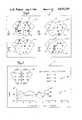
- FIG. 2is a diagram illustrating typical electrode sites used in a sixteen channel EEG electrode array.
- FIG. 3is a graph illustrating staggered time intervals used in an embodiment of the present invention referred to as Interval Overlap Processing.
- FIG. 4is a block diagram of a portion of the EEG signal analyzer of FIG. 1 as used in an embodiment referred to as Interval Subtraction Processing.
- FIGS. 5A and 5Bare graphs illustrating two different embodiments of the staggered time intervals which define selected epochs in Interval Subtraction Processing.
- FIGS. 6, 7, 8 and 9illustrate three different forms of displayed or printed output provided by the system of FIG. 1 to illustrate changes in frequency response for each EEG channel during a succession of epochs.
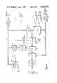
- FIG. 10is an electrical block diagram of the preferred embodiment of the signal processing module of the EEG signal analyzer of FIG. 1.
- FIG. 1shows a preferred embodiment of EEG signal analyzer 10 of the present invention.
- EEG signal analyzer 10includes EEG electrode array 12, EEG multichannel amplifier circuit 14, signal processing module 16, digital computer 18, computer disc storage 19, stimulus source 20, display 22, printer or other hard copy device 24, and keyboard 26.
- the purpose of EEG signal analyzer 10is to record and analyze EEG signals produced in response to a stimulus from stimulus source 20 (or in response to a task performed by a human subject) and to provide an output through display 22 or printer 24 which indicates the frequency response of EEG signals from various sites during a series of very short epochs.
- the epochsare of sufficiently short duration (preferably 50 milliseconds or less) so that the changes in EEG frequency response at various sites with time during the time period when cortical processing occurs can be studied.
- EEG electrode array 12includes a plurality of EEG electrodes which are placed in contact with the scalp of a human subject.
- FIG. 2is a diagram which illustrates nineteen typical sites of electrodes on a subject's head 28. When array 12 is used in a sixteen channel system, sixteen of the nineteen sites shown in FIG. 2 are used.
- the electrode sitesare identified by the commonly used designations Fp1, Fp2, F0, F3, F4, F7, F8, T3, T4, T5, T6, C0, C3, C4, P0, P3, P4, 01, and 02.
- reference electrode sitesA1 and A2 for reference electrodes which are commonly attached to one (or both) of the subject's ears.
- EEG multichannel amplifier circuit 14includes a differential amplifier for each channel, which amplifies the potential difference between a reference potential and the potential at the electrode site for that particular channel.
- the reference potentialis typically derived from one or a combination of both of the reference electrode sites A1 or A2, or is based upon an average of the potentials from all of the sites.
- the output of EEG multichannel amplifier circuit 14is an analog EEG signal for each channel.
- Signal processing module 16receives the analog EEG signals from EEG multichannel amplifier circuit 14. Signal processing module 16 samples the analog EEG signal for each channel at a rate which is greater than twice the highest frequency of interest. The sampled analog values for each channel are converted to digital values, and are stored by signal processing module 16. During each test, the sampling, digitizing and storing occurs over a time interval which is at least as long as the period of the lowest EEG signal frequency of interest, and which is initiated at a predetermined time either before or after a stimulus. In a preferred embodiment, the lowest frequency of interest is one Hertz, and therefore the time interval has a duration of at least one second. The stored digital sample values for each channel represent the amplitude of the EEG signal as a function of time.
- stimulus source 20preferably provides a visual, auditory or other sensory stimulus to the human subject
- signal processing module 16samples, digitizes and stores the EEG signals from the various channels.
- the stored digital sample valuesare transferred from signal processing module 16 to digital computer 18 and is stored in computer disc storage 19 or in random access memory (RAM) within computer 18.
- the testis typically repeated a number of times (N) using identical time intervals.
- Digital computer 18determines a weighted mean frequency value (WMF) for each epoch (i.e. a time period of interest) at each channel based upon the digital sample values received from signal processing module 16. Based upon the weighted mean frequency (WMF) values for the various epochs and channels, digital computer 18 provides an output through display 22 or printer 24 which indicates the frequency response of the EEG signals from the various channels during a series of epochs. In this way, the frequency response at various cites as a result of the stimulus can be observed and studied.
- WMFweighted mean frequency value
- each of these embodimentsinvolves the transformation of digitized waveforms from the time domain to the frequency domain.
- Each digitized waveform which is transformedhas a length which is at least as long as the period of the lowest frequency of interest and includes digital sample values which are unique to a particular epoch.
- the transformationresults in a frequency spectrum which has a frequency content which is unique to that particular epoch.
- the transformation from the time domain to the frequency domainis performed by digital computer 18 using a signal processing algorithm such as a Fat Fourier Transform.
- the transformationis performed by signal processing hardware within signal processing module 16. In either case, the result is a frequency spectrum for each channel based upon a digitized waveform which is at least as long as the period of the lowest frequency of interest and which includes a digital sample value unique to the particular epoch.
- a weighted mean frequency (WMF) value for each epoch at each channelis then calculated by a digital computer 18 based upon the corresponding frequency spectrum.
- WMFweighted mean frequency
- digital computer 18calculates a RANGE of WMF values for each channel.
- the RANGErepresents the difference between the highest and lowest WMF values for that channel.
- Digital computer 18calculates a weighted mean frequency difference (WMFD) value for each epoch at each channel.
- WMFDWMF-WMFB
- WMFBis a base line value which is a WMF value from a time interval which both begins and ends prior to the stimulus.
- the WMFB valuerepresents the weighted mean frequency at that particular channel when the human subject is unaffected by the stimulus.
- Digital computer 18calculates, for each epoch at each channel, an adjusted frequency value (AFV).
- AFVadjusted frequency value
- AFVWMFD/RANGE.
- digital computer 18Based upon the WMF values, the WMFD values, and the AFV values, digital computer 18 produces one of a number of different outputs through display 22 or printer 24.
- the outputspreferably illustrates frequency response of the EEG signals of various channels by showing AFV as a function of epoch, WMF as a function of epoch and a ranking of the various channels as a function of their WMF and AFV value for each of the epochs.
- FIG. 3shows an example of the different time intervals which are used during the Interval Overlap Processing of the present invention.
- Tthe time when the stimulus is triggered
- epochsare shown as having a 50 millisecond duration.
- Digital computer 18coordinates the operation of signal processing module 16 and stimulus source 20 so that the beginning of the interval has a predetermined time relationship to the stimulus. Depending upon the particular epoch of interest, the interval may begin before or after the stimulus.
- the time period T between the beginning of the interval and the occurrence of the stimulusis:
- T Etime duration of epoch
- Intervals A, B, C and Dare of equal length, but are staggered slightly at both ends.
- a weighted mean frequency value for Interval Ais compared with the weighted mean frequency value from Interval B, any differences in those two weighted mean frequency values are attributable to two relatively short time periods.
- the firstis designated as “Tail #2” and represents the time period during which only Interval A (but not Interval B) occurs.
- the other time periodis labeled "Epoch #2" (because it is the second 50 ms epoch after the stimulus), and represents the time period during which Interval B (but not Interval A) occurs.
- any difference in weighted mean frequency values for Interval B and Interval Cis due to the portion labeled "Tail #3" and the portion labeled "Epoch #3" in FIG. 3. Any difference between weighted mean frequency values of Interval C and Interval D is due to Tail #4 and Epoch #4.
- Interval Overlap Processinga total of N tests are performed for each of the intervals. This permits averaging of the weighted mean frequency values for each of the intervals, so as to reduce the effect of noise on the determination of a WMF value for each epoch at each channel.
- the digitized waveforms for each of the channelsare transferred from signal processing module 16 to digital computer 18.
- Table 1outlines the steps which are performed by digital computer 18 in converting the digital sample values to weighted mean frequency (WMF) values, weighted mean frequency difference (WMFD) values, and adjusted frequency values (AFV). From these values, digital computer 18 produces the outputs which are supplied through display 22 and printer 24.
- WMFweighted mean frequency
- WMFDweighted mean frequency difference
- AFVadjusted frequency values
- the digital sample values for each channel and time intervalare used to form a digitized waveform of a length equal to or greater than the period of the lowest EEG signal frequency of interest.
- Each digitized waveformis multiplied by a window function.
- the window functionis a four term Blackman-Harris window function, although other window functions may also be used in accordance with the present invention.
- Each digitized waveform(modified by the window function) is transformed from the time domain to the frequency domain to produce a frequency spectrum for the corresponding channel during that particular time interval.
- the WMF valuesare stored in RAM storage within digital computer 18 and/or in computer disc storage 19.
- the WMF value for each channelis averaged with other WMF values for that channel from preceding tests based upon the same time interval.
- Steps 1.1 through 1.5are repeated N times for each time interval until all intervals have been completed.
- the weighted mean frequency difference WMFDis calculated for each epoch at each channel.
- digital computer 18Based upon the particular display or print function selected by the user through keyboard 26, digital computer 18 displays information based upon the WMF values, the WMFD values, and the AFV values for the various channels and epochs.
- Interval Overlap Processingprovides frequency response information for epochs which are much shorter than the period of the lowest frequency of interest, a large amount of the frequency response data is based upon portions of the digitized waveform which are not of interest. This tends to minimize the effects caused by changes in frequency response from one epoch to the next.
- Internal Subtraction Processingprovides a more accurate determination of frequency response during the various epochs by cancelling out the effects of those portions of two staggered intervals which overlap.
- the weighted mean frequency values which are derived using Interval Subtraction Processingare due solely to the epoch and tail portions produced by two slightly staggered intervals (Interval A' and Interval B').
- signal processing module 16includes a pair of identical signal processing modules 16A and 16B shown in FIG. 4 which operate in parallel during each test to sample, digitize and store digital values during slightly staggered time intervals A' and B'.
- the digitized waveform corresponding to Interval A'is stored by signal processing module 16A, while the digitized waveform corresponding to Interval B' is stored by signal processing module 16B.
- FIGS. 5A and 5Bshow two different embodiments of the Interval Subtraction Processing of the present invention, in which Intervals A' and B' are used to define epochs which are much shorter duration than the period of the lowest EEG signal frequency of interest.
- the epochshave a 50 millisecond duration.
- the particular epoch which is defined in both FIG. 5A and FIG. 5Bis designated "Epoch #2", because it is the second 50 millisecond epoch subsequent to the stimulus.
- Epoch #2begins 50 milliseconds after the stimulus has been provided, and ends 100 milliseconds after the stimulus has been provided.
- T50 ms
- Interval A' and Interval B'are each of one second duration.
- digital computer 18coordinates the operation of signal processing modules 16A and 16B and stimulus source 20 to produce the desired time relationship between Intervals A' and B'.
- digital computer 18loads signal processing module A with a first digital value which represents the desired time delay before commencement of Interval A' ("Delay A" shown in FIG. 5A) and loads signal processing module 16B with a second digital value corresponding to the desired time delay before commencement of Interval B' ("Delay B" shown in FIG. 5A).
- Signal processing module 16Areceives a trigger signal from digital computer 18 when the stimulus is triggered and begins timing Delay A. When Delay A has been completed, signal processing module 16A begins Interval A', during which it samples, digitizes and stores the EEG signals for each channel.
- signal processing module 16Breceives the trigger signal from digital computer 18 when the stimulus is triggered, and begins timing Delay B. When Delay B is completed, signal processing module 16B begins Interval B' during which it samples, digitizes and stores the EEG signals for each channel.
- FIG. 5Bshows another embodiment which is used to produce Intervals A' and B'.
- Intervals A' and B'are commenced prior to the stimulus, rather than after the stimulus as in FIG. 5A.
- digital computer 18again coordinates the operation of signal processing modules 16A and 16B and stimulus source 20. In that case, digital computer 18 determines for the desired epoch (1) the time delay between the commencement of Interval B' and the commencement of Interval A' and (2) the time delay from the commencement of Interval B' until the stimulus provided by stimulus source 20 is triggered.
- the test for a particular epochis repeated N times.
- digital computer 18determines the appropriate commencement times for Intervals A and B and initiates a series of N tests.
- the digital sample values for each channelare transferred from signal processing module 16A to digital computer 18 and from signal processing module 16B to digital computer 18.
- the digital signal processing performed by digital computer 18 in the Interval Subtraction Processing embodiment of the present inventionis generally similar to that described previously with respect to the Interval Overlap Processing embodiment, with one important difference.
- digital computer 18transforms the digitized waveforms formed by the digital sample values from the two signal processing modules 16A and 16B separately to produce frequency spectrum A and B frequency spectrum for each channel and then subtracts frequency spectrum B from frequency spectrum A to produce a frequency spectrum D.
- the resulting frequency spectrum Drepresents a difference frequency spectrum which corresponds only to the epoch and tail portions defined by Interval A and Interval B. Those portions of frequency spectrum A and frequency spectrum B which are based upon the overlapping portions of Intervals A and B cancel one another.
- Table 2outlines the steps performed by digital computer 18 in the Interval Subtraction Processing of the present invention.
- the digital sample values from Intervals A and Bare used to form a part of digitized waveforms for each channel.
- the pair of digitized waveformsare slightly staggered in time, are of equal length and have a length equal to or greater than the period of the lowest signal frequency of interest. These two digital waveforms for each channel are multiplied by the window function.
- the pair of digitized waveforms (modified by the window function) for each channelare transformed independently from the time domain to the frequency domain. This independently yields a frequency spectrum A and a frequency spectrum B for each channel.
- frequency spectrum Bis subtracted from frequency spectrum A to yield a difference frequency spectrum D for each channel.
- Frequency spectrum D for each channelis used in the subsequent calculations of weighted mean frequency.
- the tailoccurs a substantial period after (in FIG. 5A) or before (in FIG. 5B) the stimulus is triggered.
- the EEG frequency response associated with the "tail”therefore, is not significantly affected by the stimulus and is in effect a "base line” or constant factor in all of the measurements.
- the EEG frequency response associated with the epochvaries significantly with time from the stimulus as well as from site to site.
- the WMF, WMFD and AFV valuescan, therefore, be attributed to the data from the epoch rather than the tail portions.
- the averaging of the WMF values for each epoch at each channel over a plurality of teststends to reduce the significance of any effect of the data from the tail. Since the frequency response during the tail is not affected to any significant degree by the stimulus, it is more likely to be random than is the frequency response from the epoch. Averaging the WMF values causes random changes in frequency response from test to test to be minimized in comparison to the consistent changes in frequency response caused by the stimulus.
- the Zero Processing embodiment of the present inventionprovides higher accuracy than Interval Overlap Processing, without requiring multiple signal processing modules operating in parallel, as in Interval Subtraction Processing.
- a total of N testsare performed using a time interval which is sufficiently long so that it includes all of the epochs which are to be analyzed.
- Digital computer 18coordinates the operation of signal processing module 16 and stimulus source 20, so that the interval is triggered a predetermined period of time prior to or after the stimulus.
- the digital sample values for each channelare transferred to digital computer 18 by signal processing module 16. The steps which are then performed by digital computer 18 are described in Table 3.
- the digital sample values corresponding to a selected epoch and channelare selected and are placed in the center of a digitized waveform with equal numbers of "0's" on opposite sides.
- the digitized waveform (as modified by the window function) for each channelis transformed from the time domain to the frequency domain to produce a frequency spectrum for that epoch and channel.
- Steps 3.1 through 3.4are repeated for each epoch and channel until a frequency spectrum for each epoch at each channel has been produced.
- the digital sample values from each channelare transferred from signal processing module to digital computer 18.
- Table 4describes the steps performed by digital computer 18 upon receiving the digital sample values.
- the digital sample values corresponding to a first predetermined portion of the time intervalare placed in the center of a first digitized waveform and are equally bounded on each side by "0's".
- the first predetermined portioneither begins or ends with one of the boundaries of the selected epoch.
- the length of the first digitized waveformis equal to or greater than the period of the lowest frequency of interest.
- the first digitized waveform(as modified by the window function) is transformed from the time domain to the frequency domain to produce a frequency spectrum A.
- the digital sample values corresponding to a second predetermined portion of the time intervalare placed within a second digitized waveform, equally bounded by "0's".
- the second predetermined portionis of equal length but is shifted in time with respect to the first portion, and either begins or ends with the other boundary of the epoch. Only one of the first and second portions, therefore, includes digital sample values from the epoch.
- the second digitized waveformis of equal length to the first digitized waveform.
- the second digitized waveform(as modified by the window function) is transformed from the time domain to the frequency domain to produce a frequency spectrum B.
- Frequency spectrum Bis subtracted from frequency spectrum A to produce a difference frequency spectrum D.
- Steps 4.1 through 4.7are repeated until a frequency spectrum D for each epoch at each channel is produced.
- Digital computer 18provides outputs through display 22 and printer 24 based upon the stored values of WMF, WMFD and AFV. The particular output selected is based upon information provided to digital computer 18 through keyboard 26 or some other user input interface (such as a light pen input device used with display 22).
- FIGS. 6, 7, 8 and 9show examples of different visual outputs which preferably are providded by the present invention through display 22, printer 24, or both.
- the particular visual output and the output deviceare user-selectable through keyboard 26.
- Visual output 30 shown in FIG. 6consists of four head graphics 32A-32D which are generally similar to the diagram shown in FIG. 2. Each head graphic 32A-32D represents one of the epochs in the series. Head graphic 32A is for Epoch #1, head graphic 32B represents Epoch #2, and so on. When more than four epochs are of interest, visual output 30 comprises multiple "screens", each of which includes a set of four different epochs. The particular "screen" of visual output 30 is user selectable through keyboard 26.
- each head graphic 32A-32Dincludes squares 34 of variable size and color.
- the location of squares 34correspond to the electrode sites of electrode array 12 which are being used.
- the particular electrode site being usedcan vary, and digital computer 18 is supplied with an indication of the sites in use and the channel which correspond to those sites by the user through keyboard 26.
- each square 34based on the sign of AFV and indicates whether WMF at that particular site during that particular epoch is greater or less than either an average or a base line weighted mean frequency value (WMFA or WMFB). If the stored value of AFV is negative, the square is colored red. Conversely, if AFV is positive, the square is colored green.
- WMFA or WMFBbase line weighted mean frequency value
- each square 34is a function of the magnitude of the AFV. The larger the magnitude, and the larger the area of square 34.
- Visual output 30 shown in FIG. 6,therefore, provides a visual representation of the frequency response at the various electrode sites from epoch-to-epoch. This permits an easy and intuitive comparison of the brain processing activity in response to a stimulus at various sites as a function of time.
- Visual output 40 shown in FIG. 7includes a head graphic 42 showing the designations for each site, a graph 44 showing weighted mean frequency WMF as a function of time for three selected sites and an information field 46 showing which curve (#1, #2, #3) corresponds to which site.
- the curves plotted in FIG. 7are based upon the stored WMF values for the selected sites (or channels) during the the various epochs.
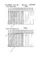
- FIG. 8shows visual output 50, which is based upon the AFV data stored by digital computer 18.
- Visual output 50 shown in FIG. 8is in the form of a chart which is displayed by display 22 or printed by printer 24.
- digital computer 18sorts the values of AFV for the various sites by magnitude and sign for each epoch.
- the site exhibiting the largest positive AFVis ranged at the top and the other sites are arranged vertically in descending order, with the site having the largest negative AFV at the bottom of each vertical column. There is a vertical column for each epoch.
- FIG. 9shows visual output 60, which is a chart similar to visual output 50, except that it is based upon WMF values rather than AFV values.
- the usercan designate a particular site (through keyboard 26), and visual output 50 or 60 will include shaded or colored boxes 62 to highlight the position of that site in the chart. This feature is illustrated in FIG. 9 with site 01.
- digital computer 18is an IBM personal computer which has had its read/write random access memory (RAM) capacity increased to at least 96K bytes of data.
- FIG. 10shows a preferred embodiment of signal processing module 16 which is used in conjunction with the IBM personal computer in this preferred embodiment.
- each module 16A and 16Bis preferably of the form shown in FIG. 10.
- the particular preferred embodiment shown in FIG. 10is for a sixteen channel EEG system.
- Signal processing module 16 shown in FIG. 10includes sixteen channel buffer 70, data buffer 72, address generator 74, control interface 76, timing circuit 78, multiplexer (MUX) 80, analog-to-digital converter (A/D) 82, input/output (I/O) control 84A and 84B, random access memory (RAM) 86, programmable delay timer 88, and control register 90. It should be noted that programmable delay timer 88 is necessary for only the Interval Substraction embodiment.
- Signal processing module 16interfaces with EEG multichannel amplifier circuit 14 through sixteen channel buffer 70.
- Signal processing module 16interfaces with digital computer 18 through data buffer 72, address generator 74, control interface 76, and timing circuit 78.
- Data buffer 72acts as a buffer between data bus 92 of computer 18 and module data bus 94. Digital data flowing between signal processing module 16 and digital computer 18 passes through data buffer 72.
- Address generator 74receives addresses from computer address bus 96 during computer read operations and generates its own addresses during sampling operations, and provides those addresses to multiplexer 80 and RAM 86 on module address bus 98.
- Control interface 76is connected to the READ, DACK, IREQ, WR and DREQ lines of digital computer 18.
- Control interface 76provides a read signal (BRD) and a write signal (BWR) to RAM 86 based upon the control signals from digital computer 18.
- Timing circuit 78 and programmable delay timer 88each receive a synchronized clock from digital computer 18.
- the timing signals produced by timing circuit 78 based upon this synchronized clock signal from computer 18are supplied to A/D converter 82, I/O controls 84A and 84B, RAM 86, and address generator 74.
- digital computer 18controls the relative timing of the commencement of the interval with respect to the triggering of the stimulus through programmable delay timer 88 and control register 90.
- Digital computer 18supplies a digital value on data bus 92 which is supplied through data buffer 72 onto module data bus 94. This digital word causes control register 90 to supply a LOAD signal to programmable delay timer 88, which loads selected bits of that digital word which represent the desired duration of a delay.
- a digital wordis provided through data bus 92, data buffer 94, and system data bus 96 to control register 90, which supplies a trigger signal SWTR to programmable delay timer 88.
- programmable delay timer 88(which is preferably a count down counter) to begin counting in response to the synchronized clock signal.
- programmable delay timer 88When programmable delay timer 88 times out, it provides a signal to timing circuit 78, which indicates the end of the delay, and the beginning of the time interval.
- Digital computer 18triggers stimulus source 20 either at the same time it initiates the test or at a predetermined time period thereafter.
- programmable delay timer 88can also be triggered as a result of an external trigger signal (EXT TR) which enables control register 90 to produce the SWTR signal.
- EXT TRexternal trigger signal
- the external trigger signalis used in those embodiments in which stimulus source 20 is triggered independently of digital computer 18. This permits signal processing module 16 to coordinate its operation with stimulus source 20 in those embodiments.
- timing circuit 78When timing circuit 78 has been enabled by the signal from programmable delay timer 88, it begins producing timing signals, and continues to produce those timing signals until the interval is completed.
- the analog EEG signals received from multichannel amplifier circuit 14are buffered by sixteen channel buffer 70 and supplied to multiplexer 80.
- the analog EEG signal from one channel at a timeis supplied by multiplexer 80 to A/D converter 82 to be sampled and digitized.
- the particular channel which is selectedis based on an address from address generator 74, which changes addresses at a rate determined by a timing signal from timing circuit 78. In a preferred embodiment of the present invention, a different channel is selected by multiplexer 80 each 245 microseconds.
- the analog EEG signal for each of the sixteen channelsis sampled and digitized 256 times. It will be understood, however, that other sample rates can also be advantageously used in the present invention.
- the digital sample values produced by A/D converter 82are supplied through I/O control 84 to RAM 86. Each sample value is stored in a different location of RAM 86, which depends upon the address supplied by address generator 74 and the time at which the signal was sampled. When the interval is completed, there are digital sample values stored in RAM 86 for each of the sixteen channels. These digital sample values represent the amplitude of the analog EEG signal for that particular channel as a function of time.
- Timing circuit 78supplies a timing signal to I/O control 80 which permits the stored data from RAM 86 to be read out of RAM 86 through I/O control 80, module data bus 94, and data buffer 72 onto computer data bus 92. It is this stored data which is then processed in the manner previously described.
- RAM 86is divided into two separate memory banks in a double buffered arrangement.
- the digital sample values from A/D converter 82are written into the first memory bank during the first half of the interval, and into the second memory bank during the second half of the interval.
- the digital sample values which have been written into the first memory bankare read out during the second half of the interval.
- the digital sample values from the second memory bankare read out after the test or during the first half of the interval of the next test. This arrangement reduces the time required to transfer the data from signal processing module 16 to digital computer 18.
- the present inventionby determining weighted mean frequencies at various sites during very short epochs, permits medical and scientific personnel to study and reconstruct the brain's processing of information. As a result, the present invention has a wide range of applications.
- the present inventionprovides a new method and system for viewing nervous system functions.
- the present inventionhas applicability as a clinical aid in the documentation of cerebral dysfunction.
- the present inventionprovides a new and powerful research tool for use in unravelling the processing of nervous activity.
- the present inventionprovides a quantitative method of assessing the effects of drugs on the central nervous system.
- the present inventionprovides a means for quantitative rather than just qualitative measures of residual functional capacity.
- An example of this type of application of the present inventionis in the determination of temporary or permanent disability of a patient after a stroke or other physical trauma.
- the system of the present inventionalso provides a means by which assessment of psychiatric patients may be possible.
- the present inventionis particularly useful in processing EEG signals, it has applicability to the processing of other time-varying biological signals (such as electrocardiograph (EKG) signals or other neurological signals) as well.
- EKGelectrocardiograph
Landscapes
- Health & Medical Sciences (AREA)
- Life Sciences & Earth Sciences (AREA)
- Biomedical Technology (AREA)
- Heart & Thoracic Surgery (AREA)
- Psychology (AREA)
- Biophysics (AREA)
- Pathology (AREA)
- Engineering & Computer Science (AREA)
- Psychiatry (AREA)
- Physics & Mathematics (AREA)
- Medical Informatics (AREA)
- Molecular Biology (AREA)
- Surgery (AREA)
- Animal Behavior & Ethology (AREA)
- General Health & Medical Sciences (AREA)
- Public Health (AREA)
- Veterinary Medicine (AREA)
- Measurement And Recording Of Electrical Phenomena And Electrical Characteristics Of The Living Body (AREA)
Abstract
Description
T=X T.sub.E Eq. 1
RANGE=WMF.sub.Highest -WMF.sub.Lowest Eq. 3
WMFD=WMF-WMFA Eq. 4A
WMFD=WMF-WMFB Eq. 4B
AFV=WMFD/RANGE Eq. 5
Claims (24)
Priority Applications (5)
| Application Number | Priority Date | Filing Date | Title |
|---|---|---|---|
| US06/527,955US4610259A (en) | 1983-08-31 | 1983-08-31 | EEG signal analysis system |
| CA000460910ACA1252515A (en) | 1983-08-31 | 1984-08-13 | Eeg signal analysis system |
| DE8484305949TDE3482009D1 (en) | 1983-08-31 | 1984-08-30 | E.E.G. SIGNAL ANALYSIS SYSTEM. |
| EP84305949AEP0137705B1 (en) | 1983-08-31 | 1984-08-30 | Eeg signal analysis system |
| JP59180836AJPS6072531A (en) | 1983-08-31 | 1984-08-31 | Eeg signal treating method and system |
Applications Claiming Priority (1)
| Application Number | Priority Date | Filing Date | Title |
|---|---|---|---|
| US06/527,955US4610259A (en) | 1983-08-31 | 1983-08-31 | EEG signal analysis system |
Publications (1)
| Publication Number | Publication Date |
|---|---|
| US4610259Atrue US4610259A (en) | 1986-09-09 |
Family
ID=24103657
Family Applications (1)
| Application Number | Title | Priority Date | Filing Date |
|---|---|---|---|
| US06/527,955Expired - LifetimeUS4610259A (en) | 1983-08-31 | 1983-08-31 | EEG signal analysis system |
Country Status (5)
| Country | Link |
|---|---|
| US (1) | US4610259A (en) |
| EP (1) | EP0137705B1 (en) |
| JP (1) | JPS6072531A (en) |
| CA (1) | CA1252515A (en) |
| DE (1) | DE3482009D1 (en) |
Cited By (117)
| Publication number | Priority date | Publication date | Assignee | Title |
|---|---|---|---|---|
| US4744029A (en)* | 1984-08-31 | 1988-05-10 | Bio-Logic Systems Corporation | Brain electrical activity analysis and mapping |
| US4776345A (en)* | 1987-09-04 | 1988-10-11 | Cns, Inc. | Interactive determination of sleep stages |
| US4794533A (en)* | 1986-11-07 | 1988-12-27 | Cns, Inc. | System activity change indicator |
| US4817627A (en)* | 1987-08-07 | 1989-04-04 | Cns, Inc. | Electroencephalographic monitoring |
| US4913160A (en)* | 1987-09-30 | 1990-04-03 | New York University | Electroencephalographic system and method using factor structure of the evoked potentials |
| US4932416A (en)* | 1987-05-01 | 1990-06-12 | Rosenfeld Joel P | Method for the analysis, display and classification of event related potentials by interpretation of P3 responses |
| US4955388A (en)* | 1985-07-30 | 1990-09-11 | Swinburne Limited | Electroencephalographic attention monitor |
| US4961428A (en)* | 1988-05-02 | 1990-10-09 | Northeastern University | Non-invasive method and apparatus for describing the electrical activity of the surface of an interior organ |
| US5003986A (en)* | 1988-11-17 | 1991-04-02 | Kenneth D. Pool, Jr. | Hierarchial analysis for processing brain stem signals to define a prominent wave |
| WO1992007509A1 (en)* | 1990-10-26 | 1992-05-14 | Massachusetts Institute Of Technology | Method and apparatus for imaging electrical activity in a biologocal system |
| DE4039648A1 (en)* | 1990-12-12 | 1992-07-16 | Rolf Wendler | Measurement value processing system for biological object - mathematically evaluates and compares with given measurement value structures |
| US5137027A (en)* | 1987-05-01 | 1992-08-11 | Rosenfeld Joel P | Method for the analysis and utilization of P300 brain waves |
| US5222503A (en)* | 1991-04-24 | 1993-06-29 | Beth Israel Hospital Association | Ambulatory electroencephalography system |
| US5275172A (en)* | 1992-04-20 | 1994-01-04 | Beth Israel Hospital Association | Electroencephalographic signal acquisition and processing system |
| US5299118A (en)* | 1987-06-26 | 1994-03-29 | Nicolet Instrument Corporation | Method and system for analysis of long term physiological polygraphic recordings |
| US5361773A (en)* | 1992-12-04 | 1994-11-08 | Beth Israel Hospital | Basal view mapping of brain activity |
| US5474082A (en)* | 1993-01-06 | 1995-12-12 | Junker; Andrew | Brain-body actuated system |
| US5601091A (en)* | 1995-08-01 | 1997-02-11 | Sonamed Corporation | Audiometric apparatus and association screening method |
| US5649061A (en)* | 1995-05-11 | 1997-07-15 | The United States Of America As Represented By The Secretary Of The Army | Device and method for estimating a mental decision |
| US5692517A (en)* | 1993-01-06 | 1997-12-02 | Junker; Andrew | Brain-body actuated system |
| US5885223A (en)* | 1995-05-31 | 1999-03-23 | Herrmann; Christoph | Process and device for assessing electroencephalograms |
| US20040133248A1 (en)* | 2002-10-15 | 2004-07-08 | Medtronic, Inc. | Channel-selective blanking for a medical device system |
| US20040133119A1 (en)* | 2002-10-15 | 2004-07-08 | Medtronic, Inc. | Scoring of sensed neurological signals for use with a medical device system |
| US20040133120A1 (en)* | 2002-10-15 | 2004-07-08 | Medtronic, Inc. | Phase shifting of neurological signals in a medical device system |
| US20040138518A1 (en)* | 2002-10-15 | 2004-07-15 | Medtronic, Inc. | Medical device system with relaying module for treatment of nervous system disorders |
| US20040138647A1 (en)* | 2002-10-15 | 2004-07-15 | Medtronic, Inc. | Cycle mode providing redundant back-up to ensure termination of treatment therapy in a medical device system |
| US20040138720A1 (en)* | 2001-04-27 | 2004-07-15 | Biophysical Mind Technologies, Ltd | Diagnosis, treatment and research of mental disorder |
| US20040138536A1 (en)* | 2002-10-15 | 2004-07-15 | Medtronic, Inc. | Clustering of recorded patient neurological activity to determine length of a neurological event |
| US20040138517A1 (en)* | 2002-10-15 | 2004-07-15 | Medtronic, Inc. | Multi-modal operation of a medical device system |
| US20040138711A1 (en)* | 2002-10-15 | 2004-07-15 | Medtronic, Inc. | Control of treatment therapy during start-up and during operation of a medical device system |
| US20040138580A1 (en)* | 2002-10-15 | 2004-07-15 | Medtronic, Inc. | Signal quality monitoring and control for a medical device system |
| US20040138516A1 (en)* | 2002-10-15 | 2004-07-15 | Medtronic, Inc. | Configuring and testing treatment therapy parameters for a medical device system |
| US20040153436A1 (en)* | 2002-10-15 | 2004-08-05 | Pope Cameron A. | Automated information management system and methods |
| US20040158119A1 (en)* | 2002-10-15 | 2004-08-12 | Medtronic, Inc. | Screening techniques for management of a nervous system disorder |
| US6792304B1 (en) | 1998-05-15 | 2004-09-14 | Swinburne Limited | Mass communication assessment system |
| US20040193028A1 (en)* | 2003-03-28 | 2004-09-30 | Vascular Control Systems, Inc. | Uterine tissue monitoring device and method |
| US20050004482A1 (en)* | 2003-07-01 | 2005-01-06 | Budimir Drakulic | Amplified system for determining parameters of a patient |
| US6856913B1 (en) | 1998-05-15 | 2005-02-15 | Swineburn Limited | Decentralized patient management method |
| US20050059896A1 (en)* | 2003-09-17 | 2005-03-17 | Budimir Drakulic | Apparatus for, and method of, determining the condition of a patient's heart |
| US20060041203A1 (en)* | 2004-08-20 | 2006-02-23 | Duke University | Methods, systems, and computer program products for neural channel selection in a multi-channel system |
| US20060129052A1 (en)* | 2004-12-09 | 2006-06-15 | Budimir Drakulic | System for, and method of, monitoring heartbeats of a patient |
| US20060155495A1 (en)* | 2002-10-15 | 2006-07-13 | Medtronic, Inc. | Synchronization and calibration of clocks for a medical device and calibrated clock |
| US20070049844A1 (en)* | 2005-08-15 | 2007-03-01 | Rosenfeld J P | System and method for a P300-based concealed information detector having combined probe and target trials |
| US20070255323A1 (en)* | 2006-04-28 | 2007-11-01 | Medtronic, Inc. | Implantable medical device for the concurrent treatment of a plurality of neurological disorders and method therefore |
| US7299083B2 (en) | 2004-12-09 | 2007-11-20 | Signalife, Inc. | Electrode for, and method of, indicating signal characteristics at particular positions in a patient's body |
| US20080033508A1 (en)* | 2002-10-15 | 2008-02-07 | Medtronic, Inc. | Clustering of recorded patient neurological activity to determine length of a neurological event |
| US20080177197A1 (en)* | 2007-01-22 | 2008-07-24 | Lee Koohyoung | Method and apparatus for quantitatively evaluating mental states based on brain wave signal processing system |
| US20080180278A1 (en)* | 2007-01-31 | 2008-07-31 | Medtronic, Inc. | Chopper-stabilized instrumentation amplifier for wireless telemetry |
| US20080269841A1 (en)* | 2007-04-30 | 2008-10-30 | Medtronic, Inc. | Chopper mixer telemetry circuit |
| US20090024049A1 (en)* | 2007-03-29 | 2009-01-22 | Neurofocus, Inc. | Cross-modality synthesis of central nervous system, autonomic nervous system, and effector data |
| US20090082829A1 (en)* | 2007-09-26 | 2009-03-26 | Medtronic, Inc. | Patient directed therapy control |
| US20090082691A1 (en)* | 2007-09-26 | 2009-03-26 | Medtronic, Inc. | Frequency selective monitoring of physiological signals |
| US20090105785A1 (en)* | 2007-09-26 | 2009-04-23 | Medtronic, Inc. | Therapy program selection |
| US20090112077A1 (en)* | 2004-01-08 | 2009-04-30 | Neurosky, Inc. | Contoured electrode |
| US20090131764A1 (en)* | 2007-10-31 | 2009-05-21 | Lee Hans C | Systems and Methods Providing En Mass Collection and Centralized Processing of Physiological Responses from Viewers |
| US20090156925A1 (en)* | 2004-01-08 | 2009-06-18 | Kyung-Soo Jin | Active dry sensor module for measurement of bioelectricity |
| US20090192556A1 (en)* | 2008-01-25 | 2009-07-30 | Medtronic, Inc. | Sleep stage detection |
| US20090214060A1 (en)* | 2008-02-13 | 2009-08-27 | Neurosky, Inc. | Audio headset with bio-signal sensors |
| US20090281408A1 (en)* | 2008-05-06 | 2009-11-12 | Neurosky, Inc. | Dry Electrode Device and Method of Assembly |
| US20090312664A1 (en)* | 2006-08-03 | 2009-12-17 | Rodriguez Villegas Esther O | Apparatus and method for obtaining eeg data |
| US20100033240A1 (en)* | 2007-01-31 | 2010-02-11 | Medtronic, Inc. | Chopper-stabilized instrumentation amplifier for impedance measurement |
| US20100114223A1 (en)* | 2008-10-31 | 2010-05-06 | Wahlstrand John D | Determining intercardiac impedance |
| US20100327887A1 (en)* | 2007-01-31 | 2010-12-30 | Medtronic, Inc. | Chopper-stabilized instrumentation amplifier for impedance measurement |
| US20110068861A1 (en)* | 2007-01-31 | 2011-03-24 | Medtronic, Inc. | Chopper-stabilized instrumentation amplifier |
| US20110078762A1 (en)* | 2009-09-29 | 2011-03-31 | Ebay, Inc. | Mobile or user device authentication and tracking |
| US8209224B2 (en) | 2009-10-29 | 2012-06-26 | The Nielsen Company (Us), Llc | Intracluster content management using neuro-response priming data |
| US8270814B2 (en) | 2009-01-21 | 2012-09-18 | The Nielsen Company (Us), Llc | Methods and apparatus for providing video with embedded media |
| US8327395B2 (en) | 2007-10-02 | 2012-12-04 | The Nielsen Company (Us), Llc | System providing actionable insights based on physiological responses from viewers of media |
| US8335715B2 (en) | 2009-11-19 | 2012-12-18 | The Nielsen Company (Us), Llc. | Advertisement exchange using neuro-response data |
| US8335716B2 (en) | 2009-11-19 | 2012-12-18 | The Nielsen Company (Us), Llc. | Multimedia advertisement exchange |
| US8386313B2 (en) | 2007-08-28 | 2013-02-26 | The Nielsen Company (Us), Llc | Stimulus placement system using subject neuro-response measurements |
| US8386312B2 (en) | 2007-05-01 | 2013-02-26 | The Nielsen Company (Us), Llc | Neuro-informatics repository system |
| US8392251B2 (en) | 2010-08-09 | 2013-03-05 | The Nielsen Company (Us), Llc | Location aware presentation of stimulus material |
| US8392253B2 (en) | 2007-05-16 | 2013-03-05 | The Nielsen Company (Us), Llc | Neuro-physiology and neuro-behavioral based stimulus targeting system |
| US8392255B2 (en) | 2007-08-29 | 2013-03-05 | The Nielsen Company (Us), Llc | Content based selection and meta tagging of advertisement breaks |
| US8392254B2 (en) | 2007-08-28 | 2013-03-05 | The Nielsen Company (Us), Llc | Consumer experience assessment system |
| US8392250B2 (en) | 2010-08-09 | 2013-03-05 | The Nielsen Company (Us), Llc | Neuro-response evaluated stimulus in virtual reality environments |
| US8396744B2 (en) | 2010-08-25 | 2013-03-12 | The Nielsen Company (Us), Llc | Effective virtual reality environments for presentation of marketing materials |
| US8464288B2 (en) | 2009-01-21 | 2013-06-11 | The Nielsen Company (Us), Llc | Methods and apparatus for providing personalized media in video |
| US8494905B2 (en) | 2007-06-06 | 2013-07-23 | The Nielsen Company (Us), Llc | Audience response analysis using simultaneous electroencephalography (EEG) and functional magnetic resonance imaging (fMRI) |
| US8494610B2 (en) | 2007-09-20 | 2013-07-23 | The Nielsen Company (Us), Llc | Analysis of marketing and entertainment effectiveness using magnetoencephalography |
| US8533042B2 (en) | 2007-07-30 | 2013-09-10 | The Nielsen Company (Us), Llc | Neuro-response stimulus and stimulus attribute resonance estimator |
| US8554325B2 (en) | 2007-10-16 | 2013-10-08 | Medtronic, Inc. | Therapy control based on a patient movement state |
| US20130331660A1 (en)* | 2012-06-07 | 2013-12-12 | Masimo Corporation | Depth of consciousness monitor |
| US8635105B2 (en) | 2007-08-28 | 2014-01-21 | The Nielsen Company (Us), Llc | Consumer experience portrayal effectiveness assessment system |
| US8655428B2 (en) | 2010-05-12 | 2014-02-18 | The Nielsen Company (Us), Llc | Neuro-response data synchronization |
| US8655437B2 (en) | 2009-08-21 | 2014-02-18 | The Nielsen Company (Us), Llc | Analysis of the mirror neuron system for evaluation of stimulus |
| US8989835B2 (en) | 2012-08-17 | 2015-03-24 | The Nielsen Company (Us), Llc | Systems and methods to gather and analyze electroencephalographic data |
| US9211411B2 (en) | 2010-08-26 | 2015-12-15 | Medtronic, Inc. | Therapy for rapid eye movement behavior disorder (RBD) |
| US9292858B2 (en) | 2012-02-27 | 2016-03-22 | The Nielsen Company (Us), Llc | Data collection system for aggregating biologically based measures in asynchronous geographically distributed public environments |
| US9320450B2 (en) | 2013-03-14 | 2016-04-26 | The Nielsen Company (Us), Llc | Methods and apparatus to gather and analyze electroencephalographic data |
| US9357240B2 (en) | 2009-01-21 | 2016-05-31 | The Nielsen Company (Us), Llc | Methods and apparatus for providing alternate media for video decoders |
| US9439150B2 (en) | 2013-03-15 | 2016-09-06 | Medtronic, Inc. | Control of spectral agressors in a physiological signal montoring device |
| US9451303B2 (en) | 2012-02-27 | 2016-09-20 | The Nielsen Company (Us), Llc | Method and system for gathering and computing an audience's neurologically-based reactions in a distributed framework involving remote storage and computing |
| US9454646B2 (en) | 2010-04-19 | 2016-09-27 | The Nielsen Company (Us), Llc | Short imagery task (SIT) research method |
| US9474462B2 (en) | 2010-07-02 | 2016-10-25 | The Trustees Of Columbia University In The City Of New York | Systems and methods for dynamic adjustable spatial granularity for EEG display |
| US9521979B2 (en) | 2013-03-15 | 2016-12-20 | Medtronic, Inc. | Control of spectral agressors in a physiological signal monitoring device |
| US9560984B2 (en) | 2009-10-29 | 2017-02-07 | The Nielsen Company (Us), Llc | Analysis of controlled and automatic attention for introduction of stimulus material |
| US9569986B2 (en) | 2012-02-27 | 2017-02-14 | The Nielsen Company (Us), Llc | System and method for gathering and analyzing biometric user feedback for use in social media and advertising applications |
| US9622703B2 (en) | 2014-04-03 | 2017-04-18 | The Nielsen Company (Us), Llc | Methods and apparatus to gather and analyze electroencephalographic data |
| US9770204B2 (en) | 2009-11-11 | 2017-09-26 | Medtronic, Inc. | Deep brain stimulation for sleep and movement disorders |
| US9814426B2 (en) | 2012-06-14 | 2017-11-14 | Medibotics Llc | Mobile wearable electromagnetic brain activity monitor |
| US9886981B2 (en) | 2007-05-01 | 2018-02-06 | The Nielsen Company (Us), Llc | Neuro-feedback based stimulus compression device |
| US9924904B2 (en) | 2014-09-02 | 2018-03-27 | Medtronic, Inc. | Power-efficient chopper amplifier |
| US9936250B2 (en) | 2015-05-19 | 2018-04-03 | The Nielsen Company (Us), Llc | Methods and apparatus to adjust content presented to an individual |
| WO2018122847A1 (en)* | 2016-12-29 | 2018-07-05 | Finkelstein Elliot Steven | A portable system and method for monitoring brain trauma |
| US10963895B2 (en) | 2007-09-20 | 2021-03-30 | Nielsen Consumer Llc | Personalized content delivery using neuro-response priming data |
| US10987015B2 (en) | 2009-08-24 | 2021-04-27 | Nielsen Consumer Llc | Dry electrodes for electroencephalography |
| US11273283B2 (en) | 2017-12-31 | 2022-03-15 | Neuroenhancement Lab, LLC | Method and apparatus for neuroenhancement to enhance emotional response |
| US11364361B2 (en) | 2018-04-20 | 2022-06-21 | Neuroenhancement Lab, LLC | System and method for inducing sleep by transplanting mental states |
| US11452839B2 (en) | 2018-09-14 | 2022-09-27 | Neuroenhancement Lab, LLC | System and method of improving sleep |
| US11481788B2 (en) | 2009-10-29 | 2022-10-25 | Nielsen Consumer Llc | Generating ratings predictions using neuro-response data |
| US11704681B2 (en) | 2009-03-24 | 2023-07-18 | Nielsen Consumer Llc | Neurological profiles for market matching and stimulus presentation |
| US11717686B2 (en) | 2017-12-04 | 2023-08-08 | Neuroenhancement Lab, LLC | Method and apparatus for neuroenhancement to facilitate learning and performance |
| US11723579B2 (en) | 2017-09-19 | 2023-08-15 | Neuroenhancement Lab, LLC | Method and apparatus for neuroenhancement |
| US11786694B2 (en) | 2019-05-24 | 2023-10-17 | NeuroLight, Inc. | Device, method, and app for facilitating sleep |
| US12280219B2 (en) | 2017-12-31 | 2025-04-22 | NeuroLight, Inc. | Method and apparatus for neuroenhancement to enhance emotional response |
Families Citing this family (8)
| Publication number | Priority date | Publication date | Assignee | Title |
|---|---|---|---|---|
| US4579125A (en)* | 1984-01-23 | 1986-04-01 | Cns, Inc. | Real-time EEG spectral analyzer |
| JPS6211433A (en)* | 1985-07-09 | 1987-01-20 | 竹田 晴見 | Actual time brain wave chart display apparatus |
| JPS6318257A (en)* | 1986-07-09 | 1988-01-26 | Takashi Mori | Plant growth status monitoring device |
| BR9007998A (en)* | 1990-02-16 | 1992-10-27 | Siemens Ag | PROCESS AND ARRANGEMENT FOR CADENCE RECOVERY |
| JP3114481B2 (en)* | 1993-05-25 | 2000-12-04 | トヨタ自動車株式会社 | Calculation method of work load evaluation index, device for the same, and work process planning method using the same |
| GB9511964D0 (en)* | 1995-06-13 | 1995-08-09 | Rdm Consultants Limited | Monitoring an EEG |
| CN104382592B (en)* | 2014-12-11 | 2016-08-31 | 康泰医学系统(秦皇岛)股份有限公司 | A kind of EEG checking device based on power spectrumanalysis algorithm |
| KR101939537B1 (en)* | 2018-07-13 | 2019-01-24 | 서울대학교산학협력단 | Method and Apparatus of Memory Improving By Brain Stimulation |
Citations (11)
| Publication number | Priority date | Publication date | Assignee | Title |
|---|---|---|---|---|
| US3495077A (en)* | 1966-04-04 | 1970-02-10 | Us Navy | Apparatus for determining the time interval correlation of the occurrence of pulses |
| US4171696A (en)* | 1978-01-30 | 1979-10-23 | Roy John E | Prevention of distortion of brainwave data due to eye movement or other artifacts |
| US4188956A (en)* | 1978-06-26 | 1980-02-19 | Roy John E | Method for the analysis, display and classification of multivariate indices of brain function--a functional electrophysiological brain scan |
| US4201224A (en)* | 1978-12-29 | 1980-05-06 | Roy John E | Electroencephalographic method and system for the quantitative description of patient brain states |
| US4216781A (en)* | 1978-06-26 | 1980-08-12 | Roy John E | Methods of electrophysiological testing |
| US4279258A (en)* | 1980-03-26 | 1981-07-21 | Roy John E | Rapid automatic electroencephalographic evaluation |
| US4407299A (en)* | 1981-05-15 | 1983-10-04 | The Children's Medical Center Corporation | Brain electrical activity mapping |
| US4408616A (en)* | 1981-05-15 | 1983-10-11 | The Children's Medical Center Corporation | Brain electricaL activity mapping |
| US4411273A (en)* | 1978-01-30 | 1983-10-25 | Roy John E | System and method for electrode pair derivations in electroencephalography |
| US4412547A (en)* | 1981-04-29 | 1983-11-01 | Neurologics, Inc. | Neurological monitoring device |
| US4493327A (en)* | 1982-07-20 | 1985-01-15 | Neurometrics, Inc. | Automatic evoked potential detection |
- 1983
- 1983-08-31USUS06/527,955patent/US4610259A/ennot_activeExpired - Lifetime
- 1984
- 1984-08-13CACA000460910Apatent/CA1252515A/ennot_activeExpired
- 1984-08-30DEDE8484305949Tpatent/DE3482009D1/ennot_activeExpired - Fee Related
- 1984-08-30EPEP84305949Apatent/EP0137705B1/ennot_activeExpired
- 1984-08-31JPJP59180836Apatent/JPS6072531A/enactivePending
Patent Citations (11)
| Publication number | Priority date | Publication date | Assignee | Title |
|---|---|---|---|---|
| US3495077A (en)* | 1966-04-04 | 1970-02-10 | Us Navy | Apparatus for determining the time interval correlation of the occurrence of pulses |
| US4171696A (en)* | 1978-01-30 | 1979-10-23 | Roy John E | Prevention of distortion of brainwave data due to eye movement or other artifacts |
| US4411273A (en)* | 1978-01-30 | 1983-10-25 | Roy John E | System and method for electrode pair derivations in electroencephalography |
| US4188956A (en)* | 1978-06-26 | 1980-02-19 | Roy John E | Method for the analysis, display and classification of multivariate indices of brain function--a functional electrophysiological brain scan |
| US4216781A (en)* | 1978-06-26 | 1980-08-12 | Roy John E | Methods of electrophysiological testing |
| US4201224A (en)* | 1978-12-29 | 1980-05-06 | Roy John E | Electroencephalographic method and system for the quantitative description of patient brain states |
| US4279258A (en)* | 1980-03-26 | 1981-07-21 | Roy John E | Rapid automatic electroencephalographic evaluation |
| US4412547A (en)* | 1981-04-29 | 1983-11-01 | Neurologics, Inc. | Neurological monitoring device |
| US4407299A (en)* | 1981-05-15 | 1983-10-04 | The Children's Medical Center Corporation | Brain electrical activity mapping |
| US4408616A (en)* | 1981-05-15 | 1983-10-11 | The Children's Medical Center Corporation | Brain electricaL activity mapping |
| US4493327A (en)* | 1982-07-20 | 1985-01-15 | Neurometrics, Inc. | Automatic evoked potential detection |
Cited By (223)
| Publication number | Priority date | Publication date | Assignee | Title |
|---|---|---|---|---|
| US4744029A (en)* | 1984-08-31 | 1988-05-10 | Bio-Logic Systems Corporation | Brain electrical activity analysis and mapping |
| US4955388A (en)* | 1985-07-30 | 1990-09-11 | Swinburne Limited | Electroencephalographic attention monitor |
| US4794533A (en)* | 1986-11-07 | 1988-12-27 | Cns, Inc. | System activity change indicator |
| US5137027A (en)* | 1987-05-01 | 1992-08-11 | Rosenfeld Joel P | Method for the analysis and utilization of P300 brain waves |
| US4932416A (en)* | 1987-05-01 | 1990-06-12 | Rosenfeld Joel P | Method for the analysis, display and classification of event related potentials by interpretation of P3 responses |
| US5299118A (en)* | 1987-06-26 | 1994-03-29 | Nicolet Instrument Corporation | Method and system for analysis of long term physiological polygraphic recordings |
| US4817627A (en)* | 1987-08-07 | 1989-04-04 | Cns, Inc. | Electroencephalographic monitoring |
| US4776345A (en)* | 1987-09-04 | 1988-10-11 | Cns, Inc. | Interactive determination of sleep stages |
| US4913160A (en)* | 1987-09-30 | 1990-04-03 | New York University | Electroencephalographic system and method using factor structure of the evoked potentials |
| US4961428A (en)* | 1988-05-02 | 1990-10-09 | Northeastern University | Non-invasive method and apparatus for describing the electrical activity of the surface of an interior organ |
| US5003986A (en)* | 1988-11-17 | 1991-04-02 | Kenneth D. Pool, Jr. | Hierarchial analysis for processing brain stem signals to define a prominent wave |
| WO1992007509A1 (en)* | 1990-10-26 | 1992-05-14 | Massachusetts Institute Of Technology | Method and apparatus for imaging electrical activity in a biologocal system |
| US5146926A (en)* | 1990-10-26 | 1992-09-15 | Massachusetts Institute Of Technology | Method and apparatus for imaging electrical activity in a biological system |
| DE4039648A1 (en)* | 1990-12-12 | 1992-07-16 | Rolf Wendler | Measurement value processing system for biological object - mathematically evaluates and compares with given measurement value structures |
| US5222503A (en)* | 1991-04-24 | 1993-06-29 | Beth Israel Hospital Association | Ambulatory electroencephalography system |
| US5275172A (en)* | 1992-04-20 | 1994-01-04 | Beth Israel Hospital Association | Electroencephalographic signal acquisition and processing system |
| US5361773A (en)* | 1992-12-04 | 1994-11-08 | Beth Israel Hospital | Basal view mapping of brain activity |
| US5474082A (en)* | 1993-01-06 | 1995-12-12 | Junker; Andrew | Brain-body actuated system |
| US5692517A (en)* | 1993-01-06 | 1997-12-02 | Junker; Andrew | Brain-body actuated system |
| US5649061A (en)* | 1995-05-11 | 1997-07-15 | The United States Of America As Represented By The Secretary Of The Army | Device and method for estimating a mental decision |
| US5885223A (en)* | 1995-05-31 | 1999-03-23 | Herrmann; Christoph | Process and device for assessing electroencephalograms |
| US5601091A (en)* | 1995-08-01 | 1997-02-11 | Sonamed Corporation | Audiometric apparatus and association screening method |
| US5916174A (en)* | 1995-08-01 | 1999-06-29 | Sonamed Corporation | Audiometric apparatus and associated screening method |
| US6856913B1 (en) | 1998-05-15 | 2005-02-15 | Swineburn Limited | Decentralized patient management method |
| US6792304B1 (en) | 1998-05-15 | 2004-09-14 | Swinburne Limited | Mass communication assessment system |
| US7610095B2 (en) | 2001-04-27 | 2009-10-27 | Biophysical Mind Technologies, Ltd. | Diagnosis, treatment, and research of brain disorders |
| US7239919B2 (en)* | 2001-04-27 | 2007-07-03 | Biophysical Mind Technologies, Ltd. | Diagnosis, treatment and research of mental disorder |
| US20040138720A1 (en)* | 2001-04-27 | 2004-07-15 | Biophysical Mind Technologies, Ltd | Diagnosis, treatment and research of mental disorder |
| US20040153436A1 (en)* | 2002-10-15 | 2004-08-05 | Pope Cameron A. | Automated information management system and methods |
| US7321837B2 (en) | 2002-10-15 | 2008-01-22 | Medtronic, Inc. | Synchronization and calibration of clocks for a medical device and calibrated clock |
| US20040138517A1 (en)* | 2002-10-15 | 2004-07-15 | Medtronic, Inc. | Multi-modal operation of a medical device system |
| US20040138711A1 (en)* | 2002-10-15 | 2004-07-15 | Medtronic, Inc. | Control of treatment therapy during start-up and during operation of a medical device system |
| US20040138580A1 (en)* | 2002-10-15 | 2004-07-15 | Medtronic, Inc. | Signal quality monitoring and control for a medical device system |
| US20040138516A1 (en)* | 2002-10-15 | 2004-07-15 | Medtronic, Inc. | Configuring and testing treatment therapy parameters for a medical device system |
| US20040152958A1 (en)* | 2002-10-15 | 2004-08-05 | Medtronic, Inc. | Timed delay for redelivery of treatment therapy for a medical device system |
| US20040133248A1 (en)* | 2002-10-15 | 2004-07-08 | Medtronic, Inc. | Channel-selective blanking for a medical device system |
| US20040158119A1 (en)* | 2002-10-15 | 2004-08-12 | Medtronic, Inc. | Screening techniques for management of a nervous system disorder |
| US20040138647A1 (en)* | 2002-10-15 | 2004-07-15 | Medtronic, Inc. | Cycle mode providing redundant back-up to ensure termination of treatment therapy in a medical device system |
| US7624293B2 (en) | 2002-10-15 | 2009-11-24 | Medtronic, Inc. | Synchronization and calibration of clocks for a medical device and calibrated clock |
| US7715919B2 (en) | 2002-10-15 | 2010-05-11 | Medtronic, Inc. | Control of treatment therapy during start-up and during operation of a medical device system |
| US20040138518A1 (en)* | 2002-10-15 | 2004-07-15 | Medtronic, Inc. | Medical device system with relaying module for treatment of nervous system disorders |
| US7917206B2 (en) | 2002-10-15 | 2011-03-29 | Medtronic, Inc. | Signal quality monitoring and control for a medical device system |
| US20040133120A1 (en)* | 2002-10-15 | 2004-07-08 | Medtronic, Inc. | Phase shifting of neurological signals in a medical device system |
| US8543214B2 (en) | 2002-10-15 | 2013-09-24 | Medtronic, Inc. | Configuring and testing treatment therapy parameters for a medical device system |
| US20060155495A1 (en)* | 2002-10-15 | 2006-07-13 | Medtronic, Inc. | Synchronization and calibration of clocks for a medical device and calibrated clock |
| US7079977B2 (en) | 2002-10-15 | 2006-07-18 | Medtronic, Inc. | Synchronization and calibration of clocks for a medical device and calibrated clock |
| US20060161384A1 (en)* | 2002-10-15 | 2006-07-20 | Medtronic, Inc. | Synchronization and calibration of clocks for a medical device and calibrated clock |
| US7146211B2 (en) | 2002-10-15 | 2006-12-05 | Medtronic, Inc. | Signal quality monitoring and control for a medical device system |
| US7149572B2 (en) | 2002-10-15 | 2006-12-12 | Medtronic, Inc. | Phase shifting of neurological signals in a medical device system |
| US8579786B2 (en) | 2002-10-15 | 2013-11-12 | Medtronic, Inc. | Screening techniques for management of a nervous system disorder |
| US20070066915A1 (en)* | 2002-10-15 | 2007-03-22 | Medtronic, Inc. | Phase Shifting of Neurological Signals in a Medical Device System |
| US20070100278A1 (en)* | 2002-10-15 | 2007-05-03 | Medtronic, Inc. | Signal Quality Monitoring And Control For A Medical Device System |
| US20040133119A1 (en)* | 2002-10-15 | 2004-07-08 | Medtronic, Inc. | Scoring of sensed neurological signals for use with a medical device system |
| US7242983B2 (en) | 2002-10-15 | 2007-07-10 | Medtronic, Inc. | Channel-selective blanking for a medical device system |
| US7280867B2 (en) | 2002-10-15 | 2007-10-09 | Medtronic, Inc. | Clustering of recorded patient neurological activity to determine length of a neurological event |
| US7282030B2 (en) | 2002-10-15 | 2007-10-16 | Medtronic, Inc. | Timed delay for redelivery of treatment therapy for a medical device system |
| US8594798B2 (en) | 2002-10-15 | 2013-11-26 | Medtronic, Inc. | Multi-modal operation of a medical device system |
| US8738136B2 (en) | 2002-10-15 | 2014-05-27 | Medtronic, Inc. | Clustering of recorded patient neurological activity to determine length of a neurological event |
| US7933646B2 (en) | 2002-10-15 | 2011-04-26 | Medtronic, Inc. | Clustering of recorded patient neurological activity to determine length of a neurological event |
| US20040138536A1 (en)* | 2002-10-15 | 2004-07-15 | Medtronic, Inc. | Clustering of recorded patient neurological activity to determine length of a neurological event |
| US20080033508A1 (en)* | 2002-10-15 | 2008-02-07 | Medtronic, Inc. | Clustering of recorded patient neurological activity to determine length of a neurological event |
| US20080064934A1 (en)* | 2002-10-15 | 2008-03-13 | Medtronic, Inc. | Clustering of recorded patient neurological activity to determine length of a neurological event |
| US7976465B2 (en) | 2002-10-15 | 2011-07-12 | Medtronic, Inc | Phase shifting of neurological signals in a medical device system |
| US9072832B2 (en) | 2002-10-15 | 2015-07-07 | Medtronic, Inc. | Clustering of recorded patient neurological activity to determine length of a neurological event |
| US8187181B2 (en) | 2002-10-15 | 2012-05-29 | Medtronic, Inc. | Scoring of sensed neurological signals for use with a medical device system |
| US20040193028A1 (en)* | 2003-03-28 | 2004-09-30 | Vascular Control Systems, Inc. | Uterine tissue monitoring device and method |
| US20050004482A1 (en)* | 2003-07-01 | 2005-01-06 | Budimir Drakulic | Amplified system for determining parameters of a patient |
| US20050059896A1 (en)* | 2003-09-17 | 2005-03-17 | Budimir Drakulic | Apparatus for, and method of, determining the condition of a patient's heart |
| US8290563B2 (en) | 2004-01-08 | 2012-10-16 | Neurosky, Inc. | Active dry sensor module for measurement of bioelectricity |
| US8301218B2 (en) | 2004-01-08 | 2012-10-30 | Neurosky, Inc. | Contoured electrode |
| US20090156925A1 (en)* | 2004-01-08 | 2009-06-18 | Kyung-Soo Jin | Active dry sensor module for measurement of bioelectricity |
| US20090112077A1 (en)* | 2004-01-08 | 2009-04-30 | Neurosky, Inc. | Contoured electrode |
| US7299089B2 (en)* | 2004-08-20 | 2007-11-20 | Duke University | Methods, systems, and computer program products for neural channel selection in a multi-channel system |
| US20060041203A1 (en)* | 2004-08-20 | 2006-02-23 | Duke University | Methods, systems, and computer program products for neural channel selection in a multi-channel system |
| US7299083B2 (en) | 2004-12-09 | 2007-11-20 | Signalife, Inc. | Electrode for, and method of, indicating signal characteristics at particular positions in a patient's body |
| US20060129052A1 (en)* | 2004-12-09 | 2006-06-15 | Budimir Drakulic | System for, and method of, monitoring heartbeats of a patient |
| US7395109B2 (en) | 2004-12-09 | 2008-07-01 | Signalife, Inc. | System for, and method of, monitoring heartbeats of a patient |
| US20090143691A1 (en)* | 2004-12-09 | 2009-06-04 | Signalife, Inc. | System for, and method of, monitoring heartbeats of a patient |
| US7376459B2 (en) | 2005-08-15 | 2008-05-20 | J. Peter Rosenfeld | System and method for P300-based concealed information detector having combined probe and target trials |
| US20070049844A1 (en)* | 2005-08-15 | 2007-03-01 | Rosenfeld J P | System and method for a P300-based concealed information detector having combined probe and target trials |
| US20070255323A1 (en)* | 2006-04-28 | 2007-11-01 | Medtronic, Inc. | Implantable medical device for the concurrent treatment of a plurality of neurological disorders and method therefore |
| US8326431B2 (en) | 2006-04-28 | 2012-12-04 | Medtronic, Inc. | Implantable medical device for the concurrent treatment of a plurality of neurological disorders and method therefore |
| US8855758B2 (en)* | 2006-08-03 | 2014-10-07 | Imperial Innovations Limited | Apparatus and method for obtaining EEG data |
| US20090312664A1 (en)* | 2006-08-03 | 2009-12-17 | Rodriguez Villegas Esther O | Apparatus and method for obtaining eeg data |
| US20080177197A1 (en)* | 2007-01-22 | 2008-07-24 | Lee Koohyoung | Method and apparatus for quantitatively evaluating mental states based on brain wave signal processing system |
| US8354881B2 (en) | 2007-01-31 | 2013-01-15 | Medtronic, Inc. | Chopper-stabilized instrumentation amplifier |
| US20100033240A1 (en)* | 2007-01-31 | 2010-02-11 | Medtronic, Inc. | Chopper-stabilized instrumentation amplifier for impedance measurement |
| US20110068861A1 (en)* | 2007-01-31 | 2011-03-24 | Medtronic, Inc. | Chopper-stabilized instrumentation amplifier |
| US9197173B2 (en) | 2007-01-31 | 2015-11-24 | Medtronic, Inc. | Chopper-stabilized instrumentation amplifier for impedance measurement |
| US20080180278A1 (en)* | 2007-01-31 | 2008-07-31 | Medtronic, Inc. | Chopper-stabilized instrumentation amplifier for wireless telemetry |
| US9615744B2 (en) | 2007-01-31 | 2017-04-11 | Medtronic, Inc. | Chopper-stabilized instrumentation amplifier for impedance measurement |
| US20100327887A1 (en)* | 2007-01-31 | 2010-12-30 | Medtronic, Inc. | Chopper-stabilized instrumentation amplifier for impedance measurement |
| US8265769B2 (en) | 2007-01-31 | 2012-09-11 | Medtronic, Inc. | Chopper-stabilized instrumentation amplifier for wireless telemetry |
| US11790393B2 (en) | 2007-03-29 | 2023-10-17 | Nielsen Consumer Llc | Analysis of marketing and entertainment effectiveness using central nervous system, autonomic nervous system, and effector data |
| US8473345B2 (en) | 2007-03-29 | 2013-06-25 | The Nielsen Company (Us), Llc | Protocol generator and presenter device for analysis of marketing and entertainment effectiveness |
| US20090024049A1 (en)* | 2007-03-29 | 2009-01-22 | Neurofocus, Inc. | Cross-modality synthesis of central nervous system, autonomic nervous system, and effector data |
| US10679241B2 (en) | 2007-03-29 | 2020-06-09 | The Nielsen Company (Us), Llc | Analysis of marketing and entertainment effectiveness using central nervous system, autonomic nervous system, and effector data |
| US11250465B2 (en) | 2007-03-29 | 2022-02-15 | Nielsen Consumer Llc | Analysis of marketing and entertainment effectiveness using central nervous system, autonomic nervous sytem, and effector data |
| US8484081B2 (en) | 2007-03-29 | 2013-07-09 | The Nielsen Company (Us), Llc | Analysis of marketing and entertainment effectiveness using central nervous system, autonomic nervous system, and effector data |
| US8781595B2 (en) | 2007-04-30 | 2014-07-15 | Medtronic, Inc. | Chopper mixer telemetry circuit |
| US9449501B2 (en) | 2007-04-30 | 2016-09-20 | Medtronics, Inc. | Chopper mixer telemetry circuit |
| US20080269841A1 (en)* | 2007-04-30 | 2008-10-30 | Medtronic, Inc. | Chopper mixer telemetry circuit |
| US9886981B2 (en) | 2007-05-01 | 2018-02-06 | The Nielsen Company (Us), Llc | Neuro-feedback based stimulus compression device |
| US8386312B2 (en) | 2007-05-01 | 2013-02-26 | The Nielsen Company (Us), Llc | Neuro-informatics repository system |
| US10580031B2 (en) | 2007-05-16 | 2020-03-03 | The Nielsen Company (Us), Llc | Neuro-physiology and neuro-behavioral based stimulus targeting system |
| US8392253B2 (en) | 2007-05-16 | 2013-03-05 | The Nielsen Company (Us), Llc | Neuro-physiology and neuro-behavioral based stimulus targeting system |
| US11049134B2 (en) | 2007-05-16 | 2021-06-29 | Nielsen Consumer Llc | Neuro-physiology and neuro-behavioral based stimulus targeting system |
| US8494905B2 (en) | 2007-06-06 | 2013-07-23 | The Nielsen Company (Us), Llc | Audience response analysis using simultaneous electroencephalography (EEG) and functional magnetic resonance imaging (fMRI) |
| US11763340B2 (en) | 2007-07-30 | 2023-09-19 | Nielsen Consumer Llc | Neuro-response stimulus and stimulus attribute resonance estimator |
| US10733625B2 (en) | 2007-07-30 | 2020-08-04 | The Nielsen Company (Us), Llc | Neuro-response stimulus and stimulus attribute resonance estimator |
| US8533042B2 (en) | 2007-07-30 | 2013-09-10 | The Nielsen Company (Us), Llc | Neuro-response stimulus and stimulus attribute resonance estimator |
| US11244345B2 (en) | 2007-07-30 | 2022-02-08 | Nielsen Consumer Llc | Neuro-response stimulus and stimulus attribute resonance estimator |
| US8392254B2 (en) | 2007-08-28 | 2013-03-05 | The Nielsen Company (Us), Llc | Consumer experience assessment system |
| US11488198B2 (en) | 2007-08-28 | 2022-11-01 | Nielsen Consumer Llc | Stimulus placement system using subject neuro-response measurements |
| US10127572B2 (en) | 2007-08-28 | 2018-11-13 | The Nielsen Company, (US), LLC | Stimulus placement system using subject neuro-response measurements |
| US10937051B2 (en) | 2007-08-28 | 2021-03-02 | The Nielsen Company (Us), Llc | Stimulus placement system using subject neuro-response measurements |
| US8386313B2 (en) | 2007-08-28 | 2013-02-26 | The Nielsen Company (Us), Llc | Stimulus placement system using subject neuro-response measurements |
| US8635105B2 (en) | 2007-08-28 | 2014-01-21 | The Nielsen Company (Us), Llc | Consumer experience portrayal effectiveness assessment system |
| US10140628B2 (en) | 2007-08-29 | 2018-11-27 | The Nielsen Company, (US), LLC | Content based selection and meta tagging of advertisement breaks |
| US8392255B2 (en) | 2007-08-29 | 2013-03-05 | The Nielsen Company (Us), Llc | Content based selection and meta tagging of advertisement breaks |
| US11610223B2 (en) | 2007-08-29 | 2023-03-21 | Nielsen Consumer Llc | Content based selection and meta tagging of advertisement breaks |
| US11023920B2 (en) | 2007-08-29 | 2021-06-01 | Nielsen Consumer Llc | Content based selection and meta tagging of advertisement breaks |
| US10963895B2 (en) | 2007-09-20 | 2021-03-30 | Nielsen Consumer Llc | Personalized content delivery using neuro-response priming data |
| US8494610B2 (en) | 2007-09-20 | 2013-07-23 | The Nielsen Company (Us), Llc | Analysis of marketing and entertainment effectiveness using magnetoencephalography |
| US8290596B2 (en) | 2007-09-26 | 2012-10-16 | Medtronic, Inc. | Therapy program selection based on patient state |
| US20090105785A1 (en)* | 2007-09-26 | 2009-04-23 | Medtronic, Inc. | Therapy program selection |
| US20090082829A1 (en)* | 2007-09-26 | 2009-03-26 | Medtronic, Inc. | Patient directed therapy control |
| US20090082691A1 (en)* | 2007-09-26 | 2009-03-26 | Medtronic, Inc. | Frequency selective monitoring of physiological signals |
| US8380314B2 (en) | 2007-09-26 | 2013-02-19 | Medtronic, Inc. | Patient directed therapy control |
| US9248288B2 (en) | 2007-09-26 | 2016-02-02 | Medtronic, Inc. | Patient directed therapy control |
| US10258798B2 (en) | 2007-09-26 | 2019-04-16 | Medtronic, Inc. | Patient directed therapy control |
| US8332883B2 (en) | 2007-10-02 | 2012-12-11 | The Nielsen Company (Us), Llc | Providing actionable insights based on physiological responses from viewers of media |
| US9571877B2 (en) | 2007-10-02 | 2017-02-14 | The Nielsen Company (Us), Llc | Systems and methods to determine media effectiveness |
| US9894399B2 (en) | 2007-10-02 | 2018-02-13 | The Nielsen Company (Us), Llc | Systems and methods to determine media effectiveness |
| US9021515B2 (en) | 2007-10-02 | 2015-04-28 | The Nielsen Company (Us), Llc | Systems and methods to determine media effectiveness |
| US8327395B2 (en) | 2007-10-02 | 2012-12-04 | The Nielsen Company (Us), Llc | System providing actionable insights based on physiological responses from viewers of media |
| US8554325B2 (en) | 2007-10-16 | 2013-10-08 | Medtronic, Inc. | Therapy control based on a patient movement state |
| US9521960B2 (en) | 2007-10-31 | 2016-12-20 | The Nielsen Company (Us), Llc | Systems and methods providing en mass collection and centralized processing of physiological responses from viewers |
| US11250447B2 (en) | 2007-10-31 | 2022-02-15 | Nielsen Consumer Llc | Systems and methods providing en mass collection and centralized processing of physiological responses from viewers |
| US10580018B2 (en) | 2007-10-31 | 2020-03-03 | The Nielsen Company (Us), Llc | Systems and methods providing EN mass collection and centralized processing of physiological responses from viewers |
| US20090131764A1 (en)* | 2007-10-31 | 2009-05-21 | Lee Hans C | Systems and Methods Providing En Mass Collection and Centralized Processing of Physiological Responses from Viewers |
| US20090192556A1 (en)* | 2008-01-25 | 2009-07-30 | Medtronic, Inc. | Sleep stage detection |
| US10165977B2 (en) | 2008-01-25 | 2019-01-01 | Medtronic, Inc. | Sleep stage detection |
| US9072870B2 (en) | 2008-01-25 | 2015-07-07 | Medtronic, Inc. | Sleep stage detection |
| US9706957B2 (en) | 2008-01-25 | 2017-07-18 | Medtronic, Inc. | Sleep stage detection |
| US8271075B2 (en) | 2008-02-13 | 2012-09-18 | Neurosky, Inc. | Audio headset with bio-signal sensors |
| US20090214060A1 (en)* | 2008-02-13 | 2009-08-27 | Neurosky, Inc. | Audio headset with bio-signal sensors |
| US20090281408A1 (en)* | 2008-05-06 | 2009-11-12 | Neurosky, Inc. | Dry Electrode Device and Method of Assembly |
| US8170637B2 (en) | 2008-05-06 | 2012-05-01 | Neurosky, Inc. | Dry electrode device and method of assembly |
| US20100114223A1 (en)* | 2008-10-31 | 2010-05-06 | Wahlstrand John D | Determining intercardiac impedance |
| US8478402B2 (en) | 2008-10-31 | 2013-07-02 | Medtronic, Inc. | Determining intercardiac impedance |
| US9826284B2 (en) | 2009-01-21 | 2017-11-21 | The Nielsen Company (Us), Llc | Methods and apparatus for providing alternate media for video decoders |
| US8955010B2 (en) | 2009-01-21 | 2015-02-10 | The Nielsen Company (Us), Llc | Methods and apparatus for providing personalized media in video |
| US8977110B2 (en) | 2009-01-21 | 2015-03-10 | The Nielsen Company (Us), Llc | Methods and apparatus for providing video with embedded media |
| US8270814B2 (en) | 2009-01-21 | 2012-09-18 | The Nielsen Company (Us), Llc | Methods and apparatus for providing video with embedded media |
| US8464288B2 (en) | 2009-01-21 | 2013-06-11 | The Nielsen Company (Us), Llc | Methods and apparatus for providing personalized media in video |
| US9357240B2 (en) | 2009-01-21 | 2016-05-31 | The Nielsen Company (Us), Llc | Methods and apparatus for providing alternate media for video decoders |
| US11704681B2 (en) | 2009-03-24 | 2023-07-18 | Nielsen Consumer Llc | Neurological profiles for market matching and stimulus presentation |
| US8655437B2 (en) | 2009-08-21 | 2014-02-18 | The Nielsen Company (Us), Llc | Analysis of the mirror neuron system for evaluation of stimulus |
| US10987015B2 (en) | 2009-08-24 | 2021-04-27 | Nielsen Consumer Llc | Dry electrodes for electroencephalography |
| US20110078762A1 (en)* | 2009-09-29 | 2011-03-31 | Ebay, Inc. | Mobile or user device authentication and tracking |
| US10269036B2 (en) | 2009-10-29 | 2019-04-23 | The Nielsen Company (Us), Llc | Analysis of controlled and automatic attention for introduction of stimulus material |
| US8762202B2 (en) | 2009-10-29 | 2014-06-24 | The Nielson Company (Us), Llc | Intracluster content management using neuro-response priming data |
| US11170400B2 (en) | 2009-10-29 | 2021-11-09 | Nielsen Consumer Llc | Analysis of controlled and automatic attention for introduction of stimulus material |
| US9560984B2 (en) | 2009-10-29 | 2017-02-07 | The Nielsen Company (Us), Llc | Analysis of controlled and automatic attention for introduction of stimulus material |
| US8209224B2 (en) | 2009-10-29 | 2012-06-26 | The Nielsen Company (Us), Llc | Intracluster content management using neuro-response priming data |
| US11669858B2 (en) | 2009-10-29 | 2023-06-06 | Nielsen Consumer Llc | Analysis of controlled and automatic attention for introduction of stimulus material |
| US10068248B2 (en) | 2009-10-29 | 2018-09-04 | The Nielsen Company (Us), Llc | Analysis of controlled and automatic attention for introduction of stimulus material |
| US11481788B2 (en) | 2009-10-29 | 2022-10-25 | Nielsen Consumer Llc | Generating ratings predictions using neuro-response data |
| US9770204B2 (en) | 2009-11-11 | 2017-09-26 | Medtronic, Inc. | Deep brain stimulation for sleep and movement disorders |
| US8335716B2 (en) | 2009-11-19 | 2012-12-18 | The Nielsen Company (Us), Llc. | Multimedia advertisement exchange |
| US8335715B2 (en) | 2009-11-19 | 2012-12-18 | The Nielsen Company (Us), Llc. | Advertisement exchange using neuro-response data |
| US9454646B2 (en) | 2010-04-19 | 2016-09-27 | The Nielsen Company (Us), Llc | Short imagery task (SIT) research method |
| US11200964B2 (en) | 2010-04-19 | 2021-12-14 | Nielsen Consumer Llc | Short imagery task (SIT) research method |
| US10248195B2 (en) | 2010-04-19 | 2019-04-02 | The Nielsen Company (Us), Llc. | Short imagery task (SIT) research method |
| US8655428B2 (en) | 2010-05-12 | 2014-02-18 | The Nielsen Company (Us), Llc | Neuro-response data synchronization |
| US9336535B2 (en) | 2010-05-12 | 2016-05-10 | The Nielsen Company (Us), Llc | Neuro-response data synchronization |
| US9474462B2 (en) | 2010-07-02 | 2016-10-25 | The Trustees Of Columbia University In The City Of New York | Systems and methods for dynamic adjustable spatial granularity for EEG display |
| US8392251B2 (en) | 2010-08-09 | 2013-03-05 | The Nielsen Company (Us), Llc | Location aware presentation of stimulus material |
| US8392250B2 (en) | 2010-08-09 | 2013-03-05 | The Nielsen Company (Us), Llc | Neuro-response evaluated stimulus in virtual reality environments |
| US8548852B2 (en) | 2010-08-25 | 2013-10-01 | The Nielsen Company (Us), Llc | Effective virtual reality environments for presentation of marketing materials |
| US8396744B2 (en) | 2010-08-25 | 2013-03-12 | The Nielsen Company (Us), Llc | Effective virtual reality environments for presentation of marketing materials |
| US9211411B2 (en) | 2010-08-26 | 2015-12-15 | Medtronic, Inc. | Therapy for rapid eye movement behavior disorder (RBD) |
| US9569986B2 (en) | 2012-02-27 | 2017-02-14 | The Nielsen Company (Us), Llc | System and method for gathering and analyzing biometric user feedback for use in social media and advertising applications |
| US9292858B2 (en) | 2012-02-27 | 2016-03-22 | The Nielsen Company (Us), Llc | Data collection system for aggregating biologically based measures in asynchronous geographically distributed public environments |
| US9451303B2 (en) | 2012-02-27 | 2016-09-20 | The Nielsen Company (Us), Llc | Method and system for gathering and computing an audience's neurologically-based reactions in a distributed framework involving remote storage and computing |
| US10881348B2 (en) | 2012-02-27 | 2021-01-05 | The Nielsen Company (Us), Llc | System and method for gathering and analyzing biometric user feedback for use in social media and advertising applications |
| US10542903B2 (en)* | 2012-06-07 | 2020-01-28 | Masimo Corporation | Depth of consciousness monitor |
| US20130331660A1 (en)* | 2012-06-07 | 2013-12-12 | Masimo Corporation | Depth of consciousness monitor |
| US12383194B2 (en) | 2012-06-07 | 2025-08-12 | Masimo Corporation | Depth of consciousness monitor |
| US9814426B2 (en) | 2012-06-14 | 2017-11-14 | Medibotics Llc | Mobile wearable electromagnetic brain activity monitor |
| US10842403B2 (en) | 2012-08-17 | 2020-11-24 | The Nielsen Company (Us), Llc | Systems and methods to gather and analyze electroencephalographic data |
| US10779745B2 (en) | 2012-08-17 | 2020-09-22 | The Nielsen Company (Us), Llc | Systems and methods to gather and analyze electroencephalographic data |
| US9907482B2 (en) | 2012-08-17 | 2018-03-06 | The Nielsen Company (Us), Llc | Systems and methods to gather and analyze electroencephalographic data |
| US11980469B2 (en) | 2012-08-17 | 2024-05-14 | Nielsen Company | Systems and methods to gather and analyze electroencephalographic data |
| US8989835B2 (en) | 2012-08-17 | 2015-03-24 | The Nielsen Company (Us), Llc | Systems and methods to gather and analyze electroencephalographic data |
| US9060671B2 (en) | 2012-08-17 | 2015-06-23 | The Nielsen Company (Us), Llc | Systems and methods to gather and analyze electroencephalographic data |
| US9215978B2 (en) | 2012-08-17 | 2015-12-22 | The Nielsen Company (Us), Llc | Systems and methods to gather and analyze electroencephalographic data |
| US11076807B2 (en) | 2013-03-14 | 2021-08-03 | Nielsen Consumer Llc | Methods and apparatus to gather and analyze electroencephalographic data |
| US9320450B2 (en) | 2013-03-14 | 2016-04-26 | The Nielsen Company (Us), Llc | Methods and apparatus to gather and analyze electroencephalographic data |
| US9668694B2 (en) | 2013-03-14 | 2017-06-06 | The Nielsen Company (Us), Llc | Methods and apparatus to gather and analyze electroencephalographic data |
| US9521979B2 (en) | 2013-03-15 | 2016-12-20 | Medtronic, Inc. | Control of spectral agressors in a physiological signal monitoring device |
| US9439150B2 (en) | 2013-03-15 | 2016-09-06 | Medtronic, Inc. | Control of spectral agressors in a physiological signal montoring device |
| US11141108B2 (en) | 2014-04-03 | 2021-10-12 | Nielsen Consumer Llc | Methods and apparatus to gather and analyze electroencephalographic data |
| US9622702B2 (en) | 2014-04-03 | 2017-04-18 | The Nielsen Company (Us), Llc | Methods and apparatus to gather and analyze electroencephalographic data |
| US9622703B2 (en) | 2014-04-03 | 2017-04-18 | The Nielsen Company (Us), Llc | Methods and apparatus to gather and analyze electroencephalographic data |
| US9924904B2 (en) | 2014-09-02 | 2018-03-27 | Medtronic, Inc. | Power-efficient chopper amplifier |
| US11290779B2 (en) | 2015-05-19 | 2022-03-29 | Nielsen Consumer Llc | Methods and apparatus to adjust content presented to an individual |
| US9936250B2 (en) | 2015-05-19 | 2018-04-03 | The Nielsen Company (Us), Llc | Methods and apparatus to adjust content presented to an individual |
| US10771844B2 (en) | 2015-05-19 | 2020-09-08 | The Nielsen Company (Us), Llc | Methods and apparatus to adjust content presented to an individual |
| US11406315B2 (en) | 2016-12-29 | 2022-08-09 | Elliot Steven Finkelstein | Portable system and method for monitoring brain trauma |
| WO2018122847A1 (en)* | 2016-12-29 | 2018-07-05 | Finkelstein Elliot Steven | A portable system and method for monitoring brain trauma |
| US11723579B2 (en) | 2017-09-19 | 2023-08-15 | Neuroenhancement Lab, LLC | Method and apparatus for neuroenhancement |
| US11717686B2 (en) | 2017-12-04 | 2023-08-08 | Neuroenhancement Lab, LLC | Method and apparatus for neuroenhancement to facilitate learning and performance |
| US11478603B2 (en) | 2017-12-31 | 2022-10-25 | Neuroenhancement Lab, LLC | Method and apparatus for neuroenhancement to enhance emotional response |
| US11318277B2 (en) | 2017-12-31 | 2022-05-03 | Neuroenhancement Lab, LLC | Method and apparatus for neuroenhancement to enhance emotional response |
| US12280219B2 (en) | 2017-12-31 | 2025-04-22 | NeuroLight, Inc. | Method and apparatus for neuroenhancement to enhance emotional response |
| US11273283B2 (en) | 2017-12-31 | 2022-03-15 | Neuroenhancement Lab, LLC | Method and apparatus for neuroenhancement to enhance emotional response |
| US12383696B2 (en) | 2017-12-31 | 2025-08-12 | NeuroLight, Inc. | Method and apparatus for neuroenhancement to enhance emotional response |
| US12397128B2 (en) | 2017-12-31 | 2025-08-26 | NeuroLight, Inc. | Method and apparatus for neuroenhancement to enhance emotional response |
| US11364361B2 (en) | 2018-04-20 | 2022-06-21 | Neuroenhancement Lab, LLC | System and method for inducing sleep by transplanting mental states |
| US11452839B2 (en) | 2018-09-14 | 2022-09-27 | Neuroenhancement Lab, LLC | System and method of improving sleep |
| US11786694B2 (en) | 2019-05-24 | 2023-10-17 | NeuroLight, Inc. | Device, method, and app for facilitating sleep |
Also Published As
| Publication number | Publication date |
|---|---|
| EP0137705B1 (en) | 1990-04-18 |
| CA1252515A (en) | 1989-04-11 |
| DE3482009D1 (en) | 1990-05-23 |
| EP0137705A3 (en) | 1985-12-18 |
| EP0137705A2 (en) | 1985-04-17 |
| JPS6072531A (en) | 1985-04-24 |
Similar Documents
| Publication | Publication Date | Title |
|---|---|---|
| US4610259A (en) | EEG signal analysis system | |
| US4579125A (en) | Real-time EEG spectral analyzer | |
| US4736307A (en) | Microcomputer-based system for the on-line analysis and topographic display of human brain electrical activity | |
| US4583190A (en) | Microcomputer based system for performing fast Fourier transforms | |
| EP0267710B1 (en) | System activity change indicator | |
| Klimesch et al. | Interindividual differences in alpha and theta power reflect memory performance | |
| Gregory et al. | An electroencephalographic processing algorithm specifically intended for analysis of cerebral electrical activity | |
| Roberts et al. | Temporal and spatial complexity measures for electroencephalogram based brain-computer interfacing | |
| US4776345A (en) | Interactive determination of sleep stages | |
| US6195576B1 (en) | Quantitative magnetoencephalogram system and method | |
| Tervaniemi et al. | Absolute pitch and event-related brain potentials | |
| US3841309A (en) | Method of analyzing cerebral electrical activity | |
| Suzuki | Phase relationships of alpha rhythm in man | |
| US6343229B1 (en) | Device for measurement and analysis of brain activity of both cerebral hemispheres in a patient | |
| US4800895A (en) | Electroencephalographic data display method and system | |
| EP0241757A2 (en) | Brain electrical activity mapping (BEAM) | |
| Aunon et al. | Detection and processing of individual components in the VEP | |
| Rebert et al. | Task-related hemispheric asymmetry of contingent negative variation | |
| RU2029492C1 (en) | Method of evaluation of bioelectric processes of brain | |
| Prodanov et al. | Software Module for Processing EEG Signals in a Biofeedback Based System | |
| Dom et al. | Using LabVIEW to Display Electrophysiological Signals, Analyze and Simulate Evoked Potentials | |
| Dascalov et al. | EEG preprocessing by an on-line amplitude-and-frequency analyser | |
| Andrew | Computation and display of EEG spectral and event-related desynchronization topographic maps | |
| Browder | A tutorial on digital measurement and analysis of analog voltage signals | |
| Cohen et al. | Evoked potential measurement and analysis on a small laboratory computer |
Legal Events
| Date | Code | Title | Description |
|---|---|---|---|
| AS | Assignment | Owner name:CNS, INC., EDEN PRAIRIE, MN A CORP. OF MN Free format text:ASSIGNMENT OF ASSIGNORS INTEREST.;ASSIGNORS:COHEN, DANIEL E.;STROBL, FREDERICK T.;REEL/FRAME:004170/0089 Effective date:19830825 | |
| STCF | Information on status: patent grant | Free format text:PATENTED CASE | |
| FEPP | Fee payment procedure | Free format text:PAYOR NUMBER ASSIGNED (ORIGINAL EVENT CODE: ASPN); ENTITY STATUS OF PATENT OWNER: LARGE ENTITY | |
| FPAY | Fee payment | Year of fee payment:4 | |
| FPAY | Fee payment | Year of fee payment:8 | |
| AS | Assignment | Owner name:AEQUITRON MEDICAL, INC., MINNESOTA Free format text:ASSIGNMENT OF ASSIGNORS INTEREST;ASSIGNOR:CNS, INC.;REEL/FRAME:007521/0896 Effective date:19950601 | |
| REFU | Refund | Free format text:REFUND - PAYMENT OF MAINTENANCE FEE, 12TH YR, SMALL ENTITY (ORIGINAL EVENT CODE: R285); ENTITY STATUS OF PATENT OWNER: LARGE ENTITY | |
| FEPP | Fee payment procedure | Free format text:PAT HLDR NO LONGER CLAIMS SMALL ENT STAT AS INDIV INVENTOR (ORIGINAL EVENT CODE: LSM1); ENTITY STATUS OF PATENT OWNER: LARGE ENTITY | |
| FPAY | Fee payment | Year of fee payment:12 |