US4610051A - Turkey thigh skinner - Google Patents
Turkey thigh skinnerDownload PDFInfo
- Publication number
- US4610051A US4610051AUS06/758,492US75849285AUS4610051AUS 4610051 AUS4610051 AUS 4610051AUS 75849285 AUS75849285 AUS 75849285AUS 4610051 AUS4610051 AUS 4610051A
- Authority
- US
- United States
- Prior art keywords
- skinner
- rollers
- support
- loading
- thigh
- Prior art date
- Legal status (The legal status is an assumption and is not a legal conclusion. Google has not performed a legal analysis and makes no representation as to the accuracy of the status listed.)
- Expired - Fee Related
Links
- 210000000689upper legAnatomy0.000titleclaimsabstractdescription27
- 244000144977poultrySpecies0.000claimsabstractdescription45
- 235000013372meatNutrition0.000claimsabstractdescription10
- 230000000712assemblyEffects0.000claimsdescription9
- 238000000429assemblyMethods0.000claimsdescription9
- 210000003739neckAnatomy0.000description4
- 210000004317gizzardAnatomy0.000description3
- 210000000481breastAnatomy0.000description2
- 238000004140cleaningMethods0.000description1
- 230000000694effectsEffects0.000description1
- 210000002414legAnatomy0.000description1
- 238000012423maintenanceMethods0.000description1
- 238000000034methodMethods0.000description1
- 238000012986modificationMethods0.000description1
- 230000004048modificationEffects0.000description1
- 238000004806packaging method and processMethods0.000description1
- 238000000926separation methodMethods0.000description1
- 230000007704transitionEffects0.000description1
- 238000011144upstream manufacturingMethods0.000description1
Images


Classifications
- A—HUMAN NECESSITIES
- A22—BUTCHERING; MEAT TREATMENT; PROCESSING POULTRY OR FISH
- A22C—PROCESSING MEAT, POULTRY, OR FISH
- A22C21/00—Processing poultry
- A22C21/0092—Skinning poultry or parts of poultry
Definitions
- the present inventionrelates to poultry processing apparatus and more particularly to a unique apparatus for removing the skin from poultry pieces, such as turkey thighs.
- Deviceshave been developed to remove skin from certain parts of poultry, such as necks, thighs and breasts. Many of these devices employ a set or pair of parallel, elongated rolls or rollers. The rollers have an intermeshing, spiral or helical cut configuration. The parallel rollers engage the skin and tear or pull the skin from the poultry part. Examples of these types of devices may be found in U.S. Pat. No. 3,119,144 entitled POULTRY GIZZARD PEELING ROLLS and issued on Jan. 28, 1964 to Hill; U.S. Pat. No. 3,579,714, entitled GIZZARD PROCESSING DEVICE and issued on May 25, 1971 to Edwards, Sr; U.S. Pat. No.
- U.S. Pat. No. 3,930,283discloses an embodiment for processing poultry necks which includes a disc knife intersecting a channel formed between the upper portions of a pair of rolls.
- the disc knifeslits the skin of the necks of poultry.
- the rollshave intermeshing, spiral configurations which engage the skin and pull the skin from the neck.
- a chain-type feeder or conveyorengages a thigh or breast part and moves the part so that the skin is held against a pair of spiral rolls. The rolls engage and remove the skin from the part.
- a unique poultry processing apparatusfor removing the skin from a poultry part.
- the apparatusincludes a frame supporting an elongated loading and stretch spike or bar, a conveyor positioned above the bar and a skinning means positioned below the bar for removing the skin from a poultry piece. Provision is made for cutting the skin as the piece is moved by the conveyor prior to engagement with the skinning means.
- the skinning meansincludes two pairs of counter-rotating, intermeshing helical cut rollers.
- the skin of the poultry pieceis cut so that each pair of rollers engages the skin flap and removes the skin from the piece. Provision is made for adjusting the relative positioning of the pairs of rollers with respect to each other and with respect to the loading spike or bar. In addition, provision is made for adjusting the nip or spacing between the rollers of each pair.
- the poultry pieceis loaded on the bar or spike so that the bar is interposed between the meat and the skin.
- the conveyorengages an upper surface of the poultry piece and moves the piece past the cutting means and past the skinning means.
- the apparatus in accordance with the present inventioneffectively removes the skin from a poultry piece or part without damaging the meat and without excess removal of meat during the skinning operation.
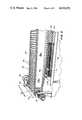
- FIG. 1is a front, perspective view of the apparatus in accordance with the present invention.
- FIG. 2is a front, perspective view of the apparatus of FIG. 1 with the top cover open;
- FIG. 3is a side, perspective view of the apparatus showing the conveyor, a portion of the loading spike or bar and one pair of counter-rotating rollers;
- FIG. 4is an enlarged, perspective view showing the skin of the poultry piece being engaged by a pair of skinning rollers
- FIG. 5is an enlarged, perspective view showing a portion of the conveyor
- FIG. 6is an enlarged, side perspective view showing the conveyor and a portion of the skinning rollers and support subassembly;
- FIG. 7is an enlarged, front, perspective view showing the infeed end of the apparatus.
- FIG. 8is a perspective, side elevational view showing a portion of the frame, the loading and stretch bar and a portion of a discharge conveyor;
- FIG. 9is a perspective view of the skinning roller support subassembly
- FIG. 10is a top, plan view of the loading bar
- FIG. 11is a side, elevational view of the loading bar
- FIG. 12is a cross-sectional view taken generally along line XII--XII of FIG. 10;
- FIG. 13is a side, elevational view of the right helical gear support tube assembly
- FIG. 14is an end, elevational view of the support tube assembly of FIG. 13;
- FIG. 15is a front, elevational view of the support tube assembly of FIG. 13;
- FIG. 16is a front, elevational view showing the right and left helical support tube assemblies
- FIG. 17is a schematic, side elevational view of an apparatus in accordance with the present invention.
- FIG. 18is a cross-sectional view taken generally along line XVIII--XVIII of FIG. 17;
- FIG. 19is an elevational view taken generally along line XIX--XIX of FIG. 17.
- FIGS. 1, 2 and 3A preferred embodiment of a skinning apparatus in accordance with the present invention is illustrated in FIGS. 1, 2 and 3 and generally designated 10.
- Apparatus 10includes a stand 12 having a rear vertical portion 14 and floor engaging members 16, 18.
- Cantilevered from vertical portion 14is a frame 20 having side members 22, 24 and a front member 26.
- a top cover or housing 28is pivotally secured to vertical portion 14 at a rear end 30 thereof. As shown in FIG. 2, cover 28 may be pivoted to a raised position providing ready access to the elements of the skinner for repair, maintenance and cleaning purposes.
- frame 20 and stand 12support an infeed table 32, suitable controls 34 and hydraulic connections 36.
- the apparatusfurther includes a conveyor subassembly 40, a loading and stretch bar 42 and a skinning roller and support subassembly 44.
- Frame 20supports a rotary cutter generally designated 46 and schematically illustrated in FIGS. 17 and 18.
- Cutter 46includes a rotary blade 48 secured to a shaft 50.
- Shaft 50is rotated by a suitable drive 52.
- drive 52is supported by side member 24 of frame 20.
- frame 20supports spaced conveyor mounting brackets 60, 62 and forward brackets 63.
- a conveyor drive 64is secured to bracket 62 (FIG. 2).
- a pair of spaced, parallel elongated conveyor supports 66, 68extend from brackets 60, 62 toward the infeed end of frame 20.
- a drive shaft 70extends between brackets 60, 62.
- Shaft 70supports a pair of spaced sprockets 72.
- Shaft 70is rotated by drive 64.
- a pair of guides 74, 76are rotatably supported at the forward ends of supports 66, 68 (FIG. 6).
- An endless chain belt 80extends around drive sprockets 72, guides 74, 76 and along supports 66, 68.
- Belt 80includes a plurality of interconnected links 82.
- Each link 82as seen in FIG. 7 for example, includes a central, inverted V portion 84 and configured ends 86. Ends 86 of one link are hooked over or looped around the ends of the next adjacent link.
- the linkstherefore, define an elongated, continuous chain belt.
- loading and stretch bar 42is a tapered, elongated member.
- Bar 42includes a mounting plate 100, an elongated stretch portion 102 and a forward, elongated loading portion 104.
- Portion 104tapers rearwardly from a free end 106 to a rear end 108. End 108 is joined to a transition portion 110 which tapers outwardly to stretch portion 102.
- Portion 104is angled upwardly from horizontal for ease of loading of a poultry part.
- Bar 42is symmetrical about a longitudinal axis 112.
- Bar 42defines an inverted V portion 114 which extends along axis 112.
- each lateral edge of stretch portion 102 adjacent mounting plate 100Extending outwardly from each lateral edge of stretch portion 102 adjacent mounting plate 100 are guide rod support mounts 116.
- mounting plate 100is welded or otherwise secured to frame 20 at the discharge end thereof.
- Bar 42is cantilevered from frame 20 and extends forwardly toward the inlet end of the apparatus.
- Elongated guide rods 118, 120are mountable along each side of stretch portion 102.
- a rear end 122 of each rodis disposed in a suitable aperture 124 defined by rod support mounts 116.
- Each support mount 116includes a plurality of spaced apertures 124.
- guide rods 120, 118are adjustably positionable outwardly from bar 42.
- bar 42extends in spaced, juxtaposed, parallel relationship to conveyor 40.
- conveyor 40will move a poultry part or piece along the top surface of bar 42 from the inlet end of the apparatus to the discharge end.
- the skinning roller and support subsassembly 44includes a subframe 130.
- Subframe 130includes front and back members 132, 134 and side members 136, 138.
- Subframe 130is supported on frame 20 and extends rearwardly from member 26 of frame 20 (FIG. 7).
- Mounted on subframe 130are right and left helical support tube assemblies 140, 142.
- Assemblies 140, 142are mirror images of each other.
- FIGS. 13, 14 and 15illustrate the right helical support tube assembly 140.
- Assembly 140includes an elongated base 144 and a pair of spaced, vertical uprights 146, 148. Extending between uprights 146, 148 is an inner support tube 150.
- An outer support tube 152is secured to base 144 by a pair of spaced mounting plates or arms 154, 156. Each arm 154, 156 is secured to base 144 by a suitable fastener 158.
- Subassemblies 163adjust the positioning of tubes 150, 152 with respect to each other.
- each arm 154, 156defines an aperture 160. Extending through aperture 160 is a threaded shaft or stud 162.
- An adjustment nut 164 and a lock nut 166are threaded on shaft 162 inside of the support arms.
- a spring 167is disposed between an outer face 168 of each arm, a washer 170, an adjustment nut 172 and a lock nut 174. Threading nut 172 toward arm 154 or 156 compresses spring 166 against its respective plate 154, 156. Spring 166 bends the arm toward the vertical uprights 146, 148. As a result, the nip or space between parallel tubes 152, 150 may be adjusted. Tube 150 in effect floats against the bias of spring 167 with respect to tube 152.
- a guide plate 180is secured to the top of each tube 150 of assemblies 140, 142.
- Plate 180is supported in spaced, parallel, generally horizontal relationship to tube 150 by a vertical mount 182.
- Plate 180is a generally flat member having an outwardly angled front face 184.
- Rear end 186 of plate 180defines a generally circular boss or mount 188.
- an end 190 of guide rod 118is received within and supported by boss 188.
- plates 180 and rods 118guide a skin flap into proper position.
- Each support tube assembly 140, 142rotatably mounts a pair of counter-rotating helically cut or spirally configured skinning rollers 200, 202.
- Each roller 200, 202includes an elongated shaft portion 204 and an elongated, helically cut portion 206 (FIG. 17).
- Shaft portion 204extends within a respective support tube 150, 152.
- a drive motor 208is coupled to shaft 204 of the outermost roller 200 supported by roller tube 152. Since helically cut portions 206 of each of the rolls or rollers 200, 202 intermesh, rotation of an outer roller 200 results in counter-rotation of an inner roller 202.
- Subassemblies 163permit tube 150 and hence outer roller 200 to float with respect to roller 202. This prevents or reduces the chance of damage to the rollers.
- Each assembly 140, 142includes an oppositely cut or beveled block 220, 222, respectively.
- Bases 140are pivotally mounted between cross pieces 132, 134 of frame 130 by pivots 224.
- a link 226has an end 228 pivoted to portion 220 by pin 230 and an end 232 pivoted to portion 220 of the left-hand assembly by a pin 234.
- a turnbuckle 240also interconnects the subassemblies. As seen in FIG. 16, turnbuckle 240 includes an eye 242 pivoted to the left-hand subassembly and an eye 244 pivoted to the right-hand subassembly.
- Rotation of threaded member 246 of turnbuckle 240moves the eyes 242, 244 toward and away from each other. This results in movement of the support tubes toward and away from each other, as indicated in FIG. 16 by arrows a.
- the support tube assemblies and hence the pair of counter-rotating rollersextend along and below the outer lateral edges of the stretch portion 102 of bar 42. The relative positioning of the skinning rollers may be readily adjusted to accommodate different size poultry parts.
- rotary disc 48 of cutting mechanism 46is positioned between support tube assemblies 140, 142 and centrally of bar 42.
- the bladeis positioned upstream of the helically cut gear portions 206 of the skinning rolls.
- Disc 48is positioned to cut the skin of a poultry part centrally as the part is moved through the apparatus by conveyor 40.
- a turkey thigh 250is slipped onto loading portion 104 of bar 42.
- the skin 252is secured to the meat only along the lateral edges of the piece.
- the pieceis slipped onto the loading spike or bar portion so that the meat is on the upper surface of the spike and the skin extends along the undersurface of the spike.
- poultry piece 250is engaged by conveyor 40 and moves along bar 42 to stretch portion 102.
- Portion 102stretches skin 252 which is slit by cutter 48.
- Cutter 48separates skin 252 into a pair of skin flaps 253, 254, as schematically shown in FIG. 19.
- the flapsare engaged by guide plates 180 so that their lower or free ends 256 are moved into nips 255 defined by skinning rollers 200, 202. As the flaps move into the spaces or nips between the rollers, the rollers engage the skin and pull the skin from the meat of poultry piece 250. As shown in FIG. 4, rods 118 extending between mounts 116 and guide plates 180 guide the skin as the poultry part moves along the skinning rollers.
- Elongated bar 42protects the meat of the poultry piece as it moves through the skinning apparatus.
- the barprovides a surface against which cutting blade 48 works to slit the skin longitudinally of the part. Blade 48 will not cut the meat of the part.
- Guide plates 180 and guide rods 118insure that the skin flaps created are properly received within the nips of the counter-rotating rollers. Plates 180 act as an adjustable extension of bar 42. The relative positioning of the pairs of rollers is readily adjusted to accommodate different size poultry pieces. Efficient and complete skin removal is accomplished.
Landscapes
- Life Sciences & Earth Sciences (AREA)
- Engineering & Computer Science (AREA)
- Wood Science & Technology (AREA)
- Zoology (AREA)
- Food Science & Technology (AREA)
- Processing Of Meat And Fish (AREA)
Abstract
Description
Claims (34)
Priority Applications (1)
| Application Number | Priority Date | Filing Date | Title |
|---|---|---|---|
| US06/758,492US4610051A (en) | 1985-07-24 | 1985-07-24 | Turkey thigh skinner |
Applications Claiming Priority (1)
| Application Number | Priority Date | Filing Date | Title |
|---|---|---|---|
| US06/758,492US4610051A (en) | 1985-07-24 | 1985-07-24 | Turkey thigh skinner |
Publications (1)
| Publication Number | Publication Date |
|---|---|
| US4610051Atrue US4610051A (en) | 1986-09-09 |
Family
ID=25051921
Family Applications (1)
| Application Number | Title | Priority Date | Filing Date |
|---|---|---|---|
| US06/758,492Expired - Fee RelatedUS4610051A (en) | 1985-07-24 | 1985-07-24 | Turkey thigh skinner |
Country Status (1)
| Country | Link |
|---|---|
| US (1) | US4610051A (en) |
Cited By (13)
| Publication number | Priority date | Publication date | Assignee | Title |
|---|---|---|---|---|
| US4723339A (en)* | 1986-04-21 | 1988-02-09 | Stork Pmt B.V. | Breast skinner |
| DE3736401C1 (en)* | 1987-10-28 | 1989-03-02 | Nordischer Maschinenbau | Device for skinning poultry carcasses |
| EP0421551A1 (en)* | 1989-10-06 | 1991-04-10 | Stork Pmt B.V. | Device for boning a piece of meat |
| EP0441124A1 (en)* | 1990-02-09 | 1991-08-14 | Nordischer Maschinenbau Rud. Baader Gmbh + Co Kg | Method and device for removing the skin from a poultry carcass |
| EP0519570A1 (en)* | 1991-06-18 | 1992-12-23 | Stork Pmt B.V. | Method and device for processing the skin of a leg of a slaughtered bird |
| US5186680A (en)* | 1991-12-30 | 1993-02-16 | Norma L. Conaway | Poultry deskinning apparatus |
| US5197917A (en)* | 1991-10-11 | 1993-03-30 | Stork Gamco, Inc. | Apparatus for removing skin from animal parts |
| EP1127492A3 (en)* | 2000-02-23 | 2002-05-29 | Systemate Group B.V. | Leg part cutter |
| US20070072530A1 (en)* | 2004-03-31 | 2007-03-29 | Mayekawa Mfg. Co., Ltd. | Apparatus and method for separating wings from breast meat of poultry |
| US20100099345A1 (en)* | 2008-08-08 | 2010-04-22 | Remington Holdings Llc | Turkey breast defatter |
| US20150264944A1 (en)* | 2014-03-18 | 2015-09-24 | Meyn Food Processing Technology B.V. | Method, processing device and processing line for mechanically processing an organ or organs taken out from slaughtered poultry |
| US9596863B2 (en)* | 2015-07-24 | 2017-03-21 | Marel Meat Processing Inc. | Automatic leg skinner |
| WO2025116731A1 (en)* | 2023-12-01 | 2025-06-05 | Foodmate B.V. | Device and method for removing skin from a poultry part |
Citations (10)
| Publication number | Priority date | Publication date | Assignee | Title |
|---|---|---|---|---|
| US3119144A (en)* | 1961-12-21 | 1964-01-28 | Carl J Hill | Poultry gizzard peeling rolls |
| US3159872A (en)* | 1963-07-22 | 1964-12-08 | Carl J Hill | Poultry gizzard processing method |
| US3579714A (en)* | 1968-11-21 | 1971-05-25 | John C Edwards | Gizzard processing device |
| US3930283A (en)* | 1973-09-06 | 1976-01-06 | Victor F. Weaver, Inc. | Machine for removing skin from pieces of poultry |
| US3930282A (en)* | 1974-09-19 | 1976-01-06 | Victor F. Weaver, Inc. | Machine for processing the backs of poultry |
| US4041572A (en)* | 1976-09-27 | 1977-08-16 | Victor F. Weaver, Inc. | Anatomical section de-boning machine |
| US4073040A (en)* | 1975-08-13 | 1978-02-14 | Hill Carl J | Machine for process of poultry gizzards |
| US4183117A (en)* | 1976-11-28 | 1980-01-15 | Pieter Meyn | Apparatus for splitting, cleaning and skinning poultry gizzards |
| US4270243A (en)* | 1979-11-29 | 1981-06-02 | Lewis Eugene J | Poultry breast splitting apparatus |
| US4395795A (en)* | 1981-03-09 | 1983-08-02 | Hazenbroek Jacobus E | Poultry gizzard processing system |
- 1985
- 1985-07-24USUS06/758,492patent/US4610051A/ennot_activeExpired - Fee Related
Patent Citations (10)
| Publication number | Priority date | Publication date | Assignee | Title |
|---|---|---|---|---|
| US3119144A (en)* | 1961-12-21 | 1964-01-28 | Carl J Hill | Poultry gizzard peeling rolls |
| US3159872A (en)* | 1963-07-22 | 1964-12-08 | Carl J Hill | Poultry gizzard processing method |
| US3579714A (en)* | 1968-11-21 | 1971-05-25 | John C Edwards | Gizzard processing device |
| US3930283A (en)* | 1973-09-06 | 1976-01-06 | Victor F. Weaver, Inc. | Machine for removing skin from pieces of poultry |
| US3930282A (en)* | 1974-09-19 | 1976-01-06 | Victor F. Weaver, Inc. | Machine for processing the backs of poultry |
| US4073040A (en)* | 1975-08-13 | 1978-02-14 | Hill Carl J | Machine for process of poultry gizzards |
| US4041572A (en)* | 1976-09-27 | 1977-08-16 | Victor F. Weaver, Inc. | Anatomical section de-boning machine |
| US4183117A (en)* | 1976-11-28 | 1980-01-15 | Pieter Meyn | Apparatus for splitting, cleaning and skinning poultry gizzards |
| US4270243A (en)* | 1979-11-29 | 1981-06-02 | Lewis Eugene J | Poultry breast splitting apparatus |
| US4395795A (en)* | 1981-03-09 | 1983-08-02 | Hazenbroek Jacobus E | Poultry gizzard processing system |
Cited By (21)
| Publication number | Priority date | Publication date | Assignee | Title |
|---|---|---|---|---|
| US4723339A (en)* | 1986-04-21 | 1988-02-09 | Stork Pmt B.V. | Breast skinner |
| DE3736401C1 (en)* | 1987-10-28 | 1989-03-02 | Nordischer Maschinenbau | Device for skinning poultry carcasses |
| EP0313824A1 (en)* | 1987-10-28 | 1989-05-03 | Nordischer Maschinenbau Rud. Baader Gmbh + Co Kg | Device for removing the skin from a poultry carcass |
| US4856143A (en)* | 1987-10-28 | 1989-08-15 | Nordischer Maschinenbau Rud. Baader Gmbh+Co Kg | Apparatus for skinning poultry carcasses |
| EP0421551A1 (en)* | 1989-10-06 | 1991-04-10 | Stork Pmt B.V. | Device for boning a piece of meat |
| US5104351A (en)* | 1989-10-06 | 1992-04-14 | Stork Pmt B.V. | Device for boning a piece of meat |
| EP0441124A1 (en)* | 1990-02-09 | 1991-08-14 | Nordischer Maschinenbau Rud. Baader Gmbh + Co Kg | Method and device for removing the skin from a poultry carcass |
| US5248277A (en)* | 1991-06-18 | 1993-09-28 | Stork Pmt B.V. | Method and device for processing the skin of a leg of a slaughtered bird |
| EP0519570A1 (en)* | 1991-06-18 | 1992-12-23 | Stork Pmt B.V. | Method and device for processing the skin of a leg of a slaughtered bird |
| US5197917A (en)* | 1991-10-11 | 1993-03-30 | Stork Gamco, Inc. | Apparatus for removing skin from animal parts |
| US5186680A (en)* | 1991-12-30 | 1993-02-16 | Norma L. Conaway | Poultry deskinning apparatus |
| EP1127492A3 (en)* | 2000-02-23 | 2002-05-29 | Systemate Group B.V. | Leg part cutter |
| US6656032B2 (en) | 2000-02-23 | 2003-12-02 | Systemate Group, B.V. | Leg part cutter |
| US7335095B2 (en)* | 2004-03-31 | 2008-02-26 | Mayekawa Mfg. Co., Ltd. | Apparatus and method for separating wings from breast meat of poultry |
| US20070072530A1 (en)* | 2004-03-31 | 2007-03-29 | Mayekawa Mfg. Co., Ltd. | Apparatus and method for separating wings from breast meat of poultry |
| US20100099345A1 (en)* | 2008-08-08 | 2010-04-22 | Remington Holdings Llc | Turkey breast defatter |
| US20150264944A1 (en)* | 2014-03-18 | 2015-09-24 | Meyn Food Processing Technology B.V. | Method, processing device and processing line for mechanically processing an organ or organs taken out from slaughtered poultry |
| US10667531B2 (en)* | 2014-03-18 | 2020-06-02 | Meyn Food Processing Technology B.V. | Method, processing device and processing line for mechanically processing an organ or organs taken out from slaughtered poultry |
| US9596863B2 (en)* | 2015-07-24 | 2017-03-21 | Marel Meat Processing Inc. | Automatic leg skinner |
| WO2025116731A1 (en)* | 2023-12-01 | 2025-06-05 | Foodmate B.V. | Device and method for removing skin from a poultry part |
| NL2036403B1 (en)* | 2023-12-01 | 2025-06-13 | Foodmate Bv | Device and method for removing skin from a poultry part |
Similar Documents
| Publication | Publication Date | Title |
|---|---|---|
| US4610051A (en) | Turkey thigh skinner | |
| EP0769247B1 (en) | Method and device for processing a cluster of organs from a slaughtered animal | |
| US5019013A (en) | On line breast halver and processor | |
| US6322438B1 (en) | Poultry leg and thigh processor | |
| US5035673A (en) | On-line breast halver | |
| US5429549A (en) | Sequential wing remover | |
| US4118829A (en) | Opening cut machine | |
| US4385421A (en) | Poultry leg/back processor | |
| US4503587A (en) | Automatic poultry breast processing machine and method | |
| US4408519A (en) | Apparatus for slicing bacon or the like | |
| NL9101050A (en) | METHOD AND APPARATUS FOR PROCESSING THE SKIN OF A LEG OF A GENDER BIRD. | |
| DK168352B1 (en) | Poultry skinning device | |
| US20230165262A1 (en) | Method and apparatus for removing skin from animal parts | |
| US3522622A (en) | Hock cutter | |
| US3364515A (en) | Device for separation of jointed animal members | |
| US5954574A (en) | Wing remover | |
| US5184974A (en) | Method and device for dividing a slaughtered bird into a front half and a back half | |
| US4531259A (en) | Meat tenderizer apparatus | |
| US4993111A (en) | Wing cutter attachment | |
| CA1176103A (en) | Apparatus for removing the breast from the eviscerated carcass of chickens or the like | |
| US3277514A (en) | Poultry neck remover | |
| US4697307A (en) | Chicken thigh skinner | |
| US4639972A (en) | Thigh deboner | |
| US2766477A (en) | Machines for dressing poultry | |
| US4644608A (en) | Thigh deboner |
Legal Events
| Date | Code | Title | Description |
|---|---|---|---|
| AS | Assignment | Owner name:FAVORITE MANUFACTURING, INC., PO BOX 9, NEW HOLLAN Free format text:ASSIGNMENT OF ASSIGNORS INTEREST.;ASSIGNORS:MARTIN, EUGENE G.;LEASE, MICHAEL E.;REEL/FRAME:004436/0156 Effective date:19850719 | |
| CC | Certificate of correction | ||
| FEPP | Fee payment procedure | Free format text:PAYOR NUMBER ASSIGNED (ORIGINAL EVENT CODE: ASPN); ENTITY STATUS OF PATENT OWNER: SMALL ENTITY | |
| FPAY | Fee payment | Year of fee payment:4 | |
| AS | Assignment | Owner name:FOODCRAFT EQUIPMENT COMPANY, INC., PENNSYLVANIA Free format text:ASSIGNMENT OF ASSIGNORS INTEREST.;ASSIGNOR:FAVORITE MANUFACTURING, INC., A PA GENERAL PARTNERSHIP;REEL/FRAME:005465/0497 Effective date:19900831 | |
| AS | Assignment | Owner name:FOOD CRAFT HOLDINGS, INC., 1105 NORTH MARKET STREE Free format text:ASSIGNMENT OF ASSIGNORS INTEREST.;ASSIGNOR:FOODCRAFT EQUIPMENT COMPANY, INC., A MD CORP.;REEL/FRAME:005584/0665 Effective date:19910108 | |
| FEPP | Fee payment procedure | Free format text:PAYOR NUMBER ASSIGNED (ORIGINAL EVENT CODE: ASPN); ENTITY STATUS OF PATENT OWNER: SMALL ENTITY Free format text:PAYER NUMBER DE-ASSIGNED (ORIGINAL EVENT CODE: RMPN); ENTITY STATUS OF PATENT OWNER: SMALL ENTITY Free format text:PAT HOLDER CLAIMS SMALL ENTITY STATUS - SMALL BUSINESS (ORIGINAL EVENT CODE: SM02); ENTITY STATUS OF PATENT OWNER: SMALL ENTITY | |
| AS | Assignment | Owner name:MARTIN, A. EUGENE, PENNSYLVANIA Free format text:SECURITY INTEREST;ASSIGNOR:FOODCRAFT EQUIPMENT COMPANY, INC.;REEL/FRAME:006604/0316 Effective date:19930326 | |
| FPAY | Fee payment | Year of fee payment:8 | |
| AS | Assignment | Owner name:FIRST VALLEY BANK, PENNSYLVANIA Free format text:SECURITY INTEREST;ASSIGNOR:FOODCRAFT EQUIPMENT COMPANY, INC.;REEL/FRAME:007013/0542 Effective date:19940418 | |
| AS | Assignment | Owner name:FOODCRAFT EQUIPMENT COMPANY, INC., PENNSYLVANIA Free format text:RELEASE BY SECURITY PARTY;ASSIGNOR:MARTIN, EUGENE;REEL/FRAME:007124/0609 Effective date:19940831 | |
| AS | Assignment | Owner name:SUMMIT BANK, NEW JERSEY Free format text:ASSIGNMENT OF ASSIGNORS INTEREST;ASSIGNOR:FOODCRAFT EQUIPMENT COMPANY, INC.;REEL/FRAME:008770/0832 Effective date:19970415 | |
| FEPP | Fee payment procedure | Free format text:PAYER NUMBER DE-ASSIGNED (ORIGINAL EVENT CODE: RMPN); ENTITY STATUS OF PATENT OWNER: SMALL ENTITY Free format text:PAYOR NUMBER ASSIGNED (ORIGINAL EVENT CODE: ASPN); ENTITY STATUS OF PATENT OWNER: SMALL ENTITY | |
| REMI | Maintenance fee reminder mailed | ||
| LAPS | Lapse for failure to pay maintenance fees | ||
| FP | Lapsed due to failure to pay maintenance fee | Effective date:19980909 | |
| STCH | Information on status: patent discontinuation | Free format text:PATENT EXPIRED DUE TO NONPAYMENT OF MAINTENANCE FEES UNDER 37 CFR 1.362 |