US4607764A - Fluent product extraction system - Google Patents
Fluent product extraction systemDownload PDFInfo
- Publication number
- US4607764A US4607764AUS06/666,756US66675684AUS4607764AUS 4607764 AUS4607764 AUS 4607764AUS 66675684 AUS66675684 AUS 66675684AUS 4607764 AUS4607764 AUS 4607764A
- Authority
- US
- United States
- Prior art keywords
- fluent material
- tip portion
- cap
- container
- fluent
- Prior art date
- Legal status (The legal status is an assumption and is not a legal conclusion. Google has not performed a legal analysis and makes no representation as to the accuracy of the status listed.)
- Expired - Lifetime
Links
Images
Classifications
- G—PHYSICS
- G01—MEASURING; TESTING
- G01F—MEASURING VOLUME, VOLUME FLOW, MASS FLOW OR LIQUID LEVEL; METERING BY VOLUME
- G01F11/00—Apparatus requiring external operation adapted at each repeated and identical operation to measure and separate a predetermined volume of fluid or fluent solid material from a supply or container, without regard to weight, and to deliver it
- G01F11/02—Apparatus requiring external operation adapted at each repeated and identical operation to measure and separate a predetermined volume of fluid or fluent solid material from a supply or container, without regard to weight, and to deliver it with measuring chambers which expand or contract during measurement
- G01F11/08—Apparatus requiring external operation adapted at each repeated and identical operation to measure and separate a predetermined volume of fluid or fluent solid material from a supply or container, without regard to weight, and to deliver it with measuring chambers which expand or contract during measurement of the diaphragm or bellows type
- G01F11/088—Apparatus requiring external operation adapted at each repeated and identical operation to measure and separate a predetermined volume of fluid or fluent solid material from a supply or container, without regard to weight, and to deliver it with measuring chambers which expand or contract during measurement of the diaphragm or bellows type using a deformable conduit-like element
Definitions
- This inventionrelates generally to the field of dispensing materials and relates particularly to the dispensing of fluent materials of a liquid, powdery, or granular nature.
- An object of the present inventionis to provide a fluent product extraction system which includes a dispensing tube (fitment) that is molded of elastomeric plastic material which is characterized by its simplicity and which is especially suitable for automatic attachment.
- Another object of the present inventionis to provide a fluent product extraction system which permits the cost of the service unit to be reduced by automatically assembling the dispensing tube to the pouch.
- a still further object of the present inventionis to provide a fluent product extraction system which includes a low cost simple device that provides a method and means for intermittently and accurately discharging the contents of a collapsible package of a fluent product, and wherein the fluent product extraction system lends itself to many different products in the food, chemical, and pharmaceutical industies where controlled, airless extraction from the flexible (collapsible) containers are used.
- a still further object of the present inventionis to provide a low cost, simple device for intermittently and accurately discharging the contents of a container by peristaltic pumping or squeezing action and which lends itself to automatic assembly procedures, the device including an elastomeric tubular body having a connector at one end for attachment to a container of fluent material and an integral discharge tip section at the other end which receives a dispensing valve and a cap or nozzle so that a conventional peristaltic pumping member may be used to dispense accurate quantities of material without after-drip.
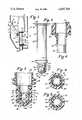
- FIG. 1is a side elevational view illustrating one application of the invention.
- FIG. 2is a side elevational view of the invention, per se, with portions broken away for clarity.
- FIG. 3is an enlarged sectional view taken along the line 3--3 of FIG. 2.
- FIG. 4is a sectional view taken along the line 4--4 of FIG. 3.
- FIG. 5is a sectional view taken along the line 5--5 of FIG. 3.
- FIG. 6is a fragmentary sectional view of a modified form of connection.
- a housing 10having a conventional peristaltic pump 11 which includes an operating member 12 pivotally connected to an arm 13, A roller 14 or other squeezing member is mounted on the end of the arm 13.
- An anvil or mounting block 15is fixed to the inside of the housing 10 on the side opposite the peristaltic pump and such anvil includes an elongated shallow channel 16 with outwardly extending bifurcated fingers 17 and 18 at opposite ends thereof.
- a collapsible, semi-rigid or substantially rigid container 19is mounted within the housing and contains a supply of fluent material in liquid, powerdy, or granular form.
- a dispensing member 22including an elongated tubular body 23 having a sealing flange 24 at one end so that the member 22 may be attached to the container 19 by means of heat, adhesives, or the like.
- the body 23is aligned with an opening (not shown) in the container to permit the fluent material within the container to flow into the body 23.
- a mounting flange 25is integrally formed on the body 23 in spaced relationship with the sealing flange 24 to receive the upper finger 17 of the mounting block between the same and prevent vertical movement of the container 19.
- the body 23is integrally formed with an axial intermediate portion 26 of reduced diameter which, in turn, is integrally connected to a tip portion 27 of further reduced diameter.
- the lower portion of the main bodypreferably, is provided with a pair of integrally formed spaced flanges 28 which receive the lower finger 18 of the mounting block 15 and prevent any elongation of the body 23 during the pumping operation.
- the intermediate portion 26has an outwardly extending annular rib 29, for a purpose to be described later.
- the tip portion 27has a generally cylindrical side wall 30 through which a plurality of openings 31 extend.
- the lower end of the tip portion 27has an outwardly extending flange 32 and terminates in a conical end wall 33.
- the flange 32is provided with a pair of detents or indents 34 on opposite sides of the tip portion which function as flow channels when material is being dispensed.
- the body 23is constructed of a polymeric material which is sealable to a polymeric container, is of sufficient stiffness and dimensional stability to permit automatic feeding during assembly, is of sufficient flexibility to permit the pumping action of a conventional peristaltic pump and has sufficient resilience and memory to return to its original shape when the pumping pressure is relieved.
- an elastomeric band 35 of predetermined hardness and elasticityis disposed about the side walls of the tip portion 27 between the intermediate portion 26 and the flange 32 as illustrated best in FIG. 3.
- the bandfunctions as a valve and closes the openings 31 until a predetermined pressure on the fluent material caused by the peristaltic pump 11 overcomes the elasticity of the band and moves the band outwardly to permit the material to flow through the openings 31 and through the detents 34 in the flange 32 of the tip portions 27.
- a cap 36is provided having a generally cylindrical side wall 37 and a conical end wall 38 which is disposed at substantially the same angle as the end wall 33 of the tip portion.
- An axial opening 39is provided in the end wall 38 to permit fluent material to discharge from the cap.
- the inner periphery of the side wall 37is of a size to form a slide fit with the exterior of the tip portion 27 and such inner periphery has a locking groove 40 which receives the rib 29 of the tip portion to retain the cap on the tip portion.
- the space 41 between the inner periphery of the side wall 37 of the cap and the outer surface of the valve forming elastomeric band 35is controlled so as to permit expansion of the elastomeric band under pressure but not enough space that the band may be axially displaced past the flange 32. This space normally is less than the thickness of the band.
- the space 42 between the outer surface of the conical end wall 33 of the tip portion and the inner surface of the conical end wall 38 of the capis controlled to provide a space that is dependent upon the viscosity of the fluent material being dispensed. For example, a space to accommodate 1,000 centipoise material is approximately 0.015 inch. Controlling the space 41 permits the establishment of a miniscus of material between the conical end wall surfaces so that no dripping of the fluent material occurs after the pumping pressure is relieved. A small amount of fluent material remains in place to seal the space 42 from any ingress of air. It is noted that the number and sizes of the openings 32 in the tip portion 27 may be varied in accordance with the viscosity and flowability of the fluent material. Further, the diameter and length of the tubular body 23 as well as the stroke of the peristaltic pump may be changed to provide more or less capacity.
- a complimentary threaded cap 43may be attached by heat or adhesives to the end of the tubular body 23. In this event, the sealing flange 24 and the mounting flange 25 may be omitted.
- the fluent materialnormally is located within the body 23, however, the low head pressure of such material is not sufficient to overcome the elasticity of the band 35 and, accordingly, no discharge and no drip occurs.
- the peristaltic pump 11is operated so that the roller 14 or other squeezing member engages and applies a pressure to the material within the body as the roller moves toward the tip portion 27 of the body.
- the pressure created by the perstaltic pumpreaches a predetermined value, the elastomeric band 35 expands and permits the fluent material to flow through the openings 31 in the tip portion and the detents 34 in the flange 32 and then flow through the space 42 and be discharged through the opening 39 in the cap 36.
- the partscan be made of any suitable material and any shapes or sizes as desired or required.
- a dispensing tube or service unitwhich has advantages over the prior patents such as prior U.S. Pat. Nos. 4,256,242 and 4,349,133.
- An important differenceis that the new dispensing tube (fitment) is molded of elastomeric plastic, redesigned for simplicity and suitable for automatic attachment. It will be noted that the cost of the service unit can be reduced by automatically assembling the dispensing tube to the pouch.
- the dispensing tube described in U.S. Pat. No. 4,256,242is elastomeric and does not have sufficient stiffness to be automatically fed and automatically attached, and the one in U.S. Pat. No. 4,349,133 is integral with the container.
- a service unitcomposed of a polymeric pouch with a polymeric dispensing tube attached thereto.
- the polymeric dispensing tubeis suitable for attachment in a form/fill/seal pouch making machine.
- the polymeric dispensing tubesuitable for attachment to a polymeric bag wherein the tube is a pumping means and contains a check valve.
- the check valve bodyis an integral part of the polymeric tube or collapsible polymeric tube.
- the deviceconsists of not more than 3 parts that includes a collapsible tube, elastomeric check valve, and cap.
- An important object of the present inventionis to provide a low cost, disposable pumping means for metered dispensing of fluidic products from a variety of containers such as collapsible polymeric bags or semi-rigid or rigid containers being adjustable as to quantity of product pumped and with no after-drip.
- the inventioncomprises (1) a molded polymeric tubular body of suitable elastomeric and memory qualities with flange means for fastening to a polymeric bag or connection to a threaded boss on a rigid container by secondary means of a screw or snap cap, flanges on the tubular section to facilitate a clamping means, a body section which will elastomerically respond to peristaltic pressure from a variety of means such as rollers, squeezing blocks, and similar devices, flanges at the lower end of the body to provide a clamping means, a check valve body section with discharge orifices occurring at appropriate locations, an enlarged diameter of the check valve body with a recessed groove to provide a locking means for a dispensing tip, fluent path grooves through the check valve retainer ring located below the orifice, a check valve retainer ring (flange) and a conical end to the body which, with the tip, will provide a means of establishing a non-dripping product discharge area, (2) a
- the entire pumpwhen assembled, consists of (1) the pump tube, (2) an elastic band check valve, and (3) a dispensing cap. Any of a variety of peristaltic pressure means can be applied to make the pump operable and it can be connected to a variety of containers as desired or required.
- the diameter and length of the pump tube and the length of the tube squeezed by the peristaltic pressure meanscan be changed to provide more or less capacity.
- the orifice size of the cap and the space between the conical surfaces of the pump tube and the capcan be adjusted so that an infinite variety of fluidic products can be dispensed without dripping. Maintaining the correct distance between conical surfaces will cause a pressure drop. Creating the correct orifice size will allow the fluid with very low head pressure to establish a miniscus across the opening. Thus, when the product is not being urged by the peristaltic pressure, no product will emerge from the cap.
- the fluid extraction system of the present inventionis an improvement over the prior patents such as prior U.S. Pat. Nos. 4,256,242 and 4,349,133.
- a low cost simple devicewhich provides a method and means for intermittently and accurately discharging the contents of a collapsible package of a fluent product.
- the devicecombines a flange capable of being joined to a collapsible package, a body section in a configuration suitable for any of a number of types of peristaltic pumping (squeezing) devices, a formed end which includes several diameters; first, a section which will retain a dispensing tip, secondly, a body with horizontal (side) discharge ports, and, thirdly, a tip section which provides one-half of a conductor for the fluent material being discharged.
- Two detents in the discharge end retainer flangeassist in guiding the flow path of the fluent product from the section containing the discharge ports to the dispensing tip.
- the two remaining parts which comprise the total pump/flanged attachment/method/check valve/and dispensing tipare: first, a flat elastomeric band of predetermined strength and, secondly, a dispensing tip.
- the elastomeric bandfunctions to retain the fluent material in the package until its sealing force over the discharge ports is overcome by the pressure of the pump.
- the tipslides over the check valve section to provide a control over the direction of flow of the fluent material being discharged by the pump.
- tip orifice size and the space between the tip and conical body sectionare determined as follows:
- a controlled spaceis determined between the tips' inside a diameter and the outside diameter of the elastomeric band sufficient to permit expansion of the elastomeric band under pressure, but not so much space as to allow its dislocation. This space is approximately one-half the thickness of the elastomeric band.
- the conical tip of the pump body and the conical form of the inside of the tipare spaced relative to the viscosity of the fluent product being dispensed.
- the space for 1,000 centipoise materialis approximately 0.015 inches.
- the present inventionis a device which is adapted to be connected to a collapsible package.
- the deviceincludes a flange which is the means for securing the device to the collapsible package or a more rigid package which can be vented.
- the elastomeric type of dispensing tubeis characterized by having memory, and this is an important part of the system.
- the devicealso includes a body section which is tubular which permits the use of a peristaltic pumping device. There is provided a check valve over the apertures and a cap is arranged over the same and this accomplishes several functions.
- the check valvemay be in the form of a flat rubber band that can be conveniently made from a latex or any elastic material.
- the other important dimensionis the distance between the check valve and the inside diameter of the cap and it must be such that it can be expanded when pumping but not to the point where it can be dislodged from its position on the tip.
- the present inventioncan be used in a variety of ways making it a very economical way of dispensing fluent products.
Landscapes
- Physics & Mathematics (AREA)
- Fluid Mechanics (AREA)
- General Physics & Mathematics (AREA)
- Closures For Containers (AREA)
Abstract
Description
Claims (3)
Priority Applications (1)
| Application Number | Priority Date | Filing Date | Title |
|---|---|---|---|
| US06/666,756US4607764A (en) | 1984-10-31 | 1984-10-31 | Fluent product extraction system |
Applications Claiming Priority (1)
| Application Number | Priority Date | Filing Date | Title |
|---|---|---|---|
| US06/666,756US4607764A (en) | 1984-10-31 | 1984-10-31 | Fluent product extraction system |
Publications (1)
| Publication Number | Publication Date |
|---|---|
| US4607764Atrue US4607764A (en) | 1986-08-26 |
Family
ID=24675328
Family Applications (1)
| Application Number | Title | Priority Date | Filing Date |
|---|---|---|---|
| US06/666,756Expired - LifetimeUS4607764A (en) | 1984-10-31 | 1984-10-31 | Fluent product extraction system |
Country Status (1)
| Country | Link |
|---|---|
| US (1) | US4607764A (en) |
Cited By (41)
| Publication number | Priority date | Publication date | Assignee | Title |
|---|---|---|---|---|
| USD336614S (en) | 1990-08-24 | 1993-06-22 | Colgate-Palmolive Company | Combined bottle and cap |
| US5265772A (en)* | 1992-10-19 | 1993-11-30 | Gojo Industries, Inc. | Dispensing apparatus with tube locator |
| US5464125A (en)* | 1994-06-16 | 1995-11-07 | Daansen; Warren S. | Dispensing apparatus having a pump tube |
| WO1995034503A1 (en)* | 1994-06-16 | 1995-12-21 | Daansen Warren S | Improved liquid dispenser |
| US5501372A (en)* | 1994-05-27 | 1996-03-26 | Daansen; Warren S. | Pump tip for fluid dispenser |
| US5971299A (en)* | 1997-01-21 | 1999-10-26 | Moen Incorporated | Kitchen faucet side spray |
| US6286732B1 (en) | 1998-08-28 | 2001-09-11 | Warren S. Daansen | Dispenser valve with increased flow capacity |
| US6394316B1 (en) | 1998-08-28 | 2002-05-28 | Warren S. Daansen | Bubble pump for dispensing particulate-ladened fluid |
| US20030222100A1 (en)* | 2002-04-26 | 2003-12-04 | Husband Peter Antony | Containers comprising at least one label made of an elastomeric material adhered to a wall |
| US20050150911A1 (en)* | 2003-12-23 | 2005-07-14 | Bach David T. | Anti-drip anti-foaming fluid dispensing system |
| US20050155987A1 (en)* | 2002-08-13 | 2005-07-21 | Daniel Py | Container and valve assembly for storing and dispensing substances, and related method |
| US7000580B1 (en)* | 2004-09-28 | 2006-02-21 | Borgwarner Inc. | Control valves with integrated check valves |
| US20060076361A1 (en)* | 2004-09-07 | 2006-04-13 | Clayton Corp. | Anti-crossover dispensing applicator |
| US20060151051A1 (en)* | 2004-12-04 | 2006-07-13 | Daniel Py | One-way valve and apparatus using the valve |
| US20070194045A1 (en)* | 2004-12-04 | 2007-08-23 | Daniel Py | One-way valve and apparatus and method of using the valve |
| US20080078781A1 (en)* | 2006-09-08 | 2008-04-03 | Daniel Py | Method for dispensing fluids |
| US20080105712A1 (en)* | 2004-01-27 | 2008-05-08 | Daniel Py | Dispenser having variable-volume storage chamber and depressible one-way valve assembly for dispensing creams and other substances |
| US20080138218A1 (en)* | 2006-12-07 | 2008-06-12 | Seiko Epson Corporation | Mciropump, tube unit, and control unit |
| US20090032610A1 (en)* | 2007-07-30 | 2009-02-05 | Michael Scot Rosko | Anti-Drip fluid delivery device |
| JP2009545497A (en)* | 2006-08-04 | 2009-12-24 | エムアールピー メディカル リサーチ アンド プロモーション エスタブリッシュメント | Bottles for storing liquids, especially pharmaceutical products |
| US20100006604A1 (en)* | 2007-02-17 | 2010-01-14 | Yaowu Ding | Lotion pump and one-way valve incorporated therein |
| US7651291B2 (en) | 2003-07-17 | 2010-01-26 | Medical Instill Technologies, Inc. | Dispenser with one-way valve for storing and dispensing metered amounts of substances |
| US20100047099A1 (en)* | 2008-08-20 | 2010-02-25 | Seiko Epson Corporation | Micropump |
| US20100080720A1 (en)* | 2008-09-29 | 2010-04-01 | Seiko Epson Corporation | Control unit, tube unit, and micropump |
| US20100096407A1 (en)* | 2004-12-10 | 2010-04-22 | Daniel Py | Container and valve assembly for storing and dispensing substances, and related method |
| US20100143168A1 (en)* | 2008-12-05 | 2010-06-10 | Seiko Epson Corporation | Tube unit, control unit, and micropump |
| US20100170458A1 (en)* | 2007-07-02 | 2010-07-08 | Borgwarner Inc. | Concentric cam with check valves in the spool for a phaser |
| US7798185B2 (en) | 2005-08-01 | 2010-09-21 | Medical Instill Technologies, Inc. | Dispenser and method for storing and dispensing sterile food product |
| US7861750B2 (en) | 2003-05-12 | 2011-01-04 | Medical Instill Technologies, Inc. | Dispenser and apparatus and method of filling a dispenser |
| US20120048423A1 (en)* | 2009-05-05 | 2012-03-01 | Sidel Participations | Filling machine with a variable filling rate |
| US20120193376A1 (en)* | 2011-02-01 | 2012-08-02 | Sakura Finetek U.S.A., Inc. | Fluid dispensing system |
| US8240521B2 (en) | 2000-10-23 | 2012-08-14 | Medical Instill Technologies, Inc. | Fluid dispenser having a one-way valve, pump, variable-volume storage chamber, and a needle penetrable and laser resealable portion |
| US20120328219A1 (en)* | 2011-06-21 | 2012-12-27 | Miura Co., Ltd. | Medicine package |
| US8376189B2 (en) | 2010-05-07 | 2013-02-19 | Alps Llc | Dispensing machine valve and method |
| US20130105521A1 (en)* | 2009-10-23 | 2013-05-02 | Nestec S.A. | Method and device for aseptically dispensing multiple portions of a fluid |
| US8757436B2 (en) | 2000-10-23 | 2014-06-24 | Medical Instill Technologies, Inc. | Method for dispensing ophthalmic fluid |
| US8932543B2 (en) | 2011-09-21 | 2015-01-13 | Sakura Finetek U.S.A., Inc. | Automated staining system and reaction chamber |
| US8984853B2 (en) | 2010-05-21 | 2015-03-24 | United Technologies Corporation | Accessing a valve assembly of a turbomachine |
| US9518899B2 (en) | 2003-08-11 | 2016-12-13 | Sakura Finetek U.S.A., Inc. | Automated reagent dispensing system and method of operation |
| US9612230B2 (en) | 2011-06-21 | 2017-04-04 | Miura Co., Ltd. | Water quality measuring device |
| US20220240536A1 (en)* | 2019-05-14 | 2022-08-04 | Soremartec S.A. | Dispensing group for a machine for dispensing foodstuff creams |
Citations (5)
| Publication number | Priority date | Publication date | Assignee | Title |
|---|---|---|---|---|
| GB659403A (en)* | 1948-01-07 | 1951-10-24 | Aage Christiansen | Closing device for collapsible tubes |
| FR2227728A5 (en)* | 1973-04-26 | 1974-11-22 | Monoplast | Intermittent liquid pouring spout - has cup facing inlet nozzle inside peripheral skirt forming annular outlet |
| US4256242A (en)* | 1979-10-23 | 1981-03-17 | Christine William C | Dispenser having a roller for squeezing amounts from a tube |
| US4261484A (en)* | 1978-08-02 | 1981-04-14 | Costa L Da | Non-return valve unit with drip prevention and controlled discharge |
| US4334640A (en)* | 1977-08-08 | 1982-06-15 | Douwe Egberts Koninklijke Tabaksfabriek-Koffiebranderijen-Theehandel B.V. | Exchangeable concentrate container for beverage dispensing machines |
- 1984
- 1984-10-31USUS06/666,756patent/US4607764A/ennot_activeExpired - Lifetime
Patent Citations (5)
| Publication number | Priority date | Publication date | Assignee | Title |
|---|---|---|---|---|
| GB659403A (en)* | 1948-01-07 | 1951-10-24 | Aage Christiansen | Closing device for collapsible tubes |
| FR2227728A5 (en)* | 1973-04-26 | 1974-11-22 | Monoplast | Intermittent liquid pouring spout - has cup facing inlet nozzle inside peripheral skirt forming annular outlet |
| US4334640A (en)* | 1977-08-08 | 1982-06-15 | Douwe Egberts Koninklijke Tabaksfabriek-Koffiebranderijen-Theehandel B.V. | Exchangeable concentrate container for beverage dispensing machines |
| US4261484A (en)* | 1978-08-02 | 1981-04-14 | Costa L Da | Non-return valve unit with drip prevention and controlled discharge |
| US4256242A (en)* | 1979-10-23 | 1981-03-17 | Christine William C | Dispenser having a roller for squeezing amounts from a tube |
Cited By (104)
| Publication number | Priority date | Publication date | Assignee | Title |
|---|---|---|---|---|
| USD336614S (en) | 1990-08-24 | 1993-06-22 | Colgate-Palmolive Company | Combined bottle and cap |
| US5265772A (en)* | 1992-10-19 | 1993-11-30 | Gojo Industries, Inc. | Dispensing apparatus with tube locator |
| US5501372A (en)* | 1994-05-27 | 1996-03-26 | Daansen; Warren S. | Pump tip for fluid dispenser |
| US5464125A (en)* | 1994-06-16 | 1995-11-07 | Daansen; Warren S. | Dispensing apparatus having a pump tube |
| WO1995034503A1 (en)* | 1994-06-16 | 1995-12-21 | Daansen Warren S | Improved liquid dispenser |
| US5971299A (en)* | 1997-01-21 | 1999-10-26 | Moen Incorporated | Kitchen faucet side spray |
| US6394316B1 (en) | 1998-08-28 | 2002-05-28 | Warren S. Daansen | Bubble pump for dispensing particulate-ladened fluid |
| US6286732B1 (en) | 1998-08-28 | 2001-09-11 | Warren S. Daansen | Dispenser valve with increased flow capacity |
| US9725228B2 (en) | 2000-10-23 | 2017-08-08 | Dr. Py Institute Llc | Fluid dispenser having a one-way valve, pump, variable-volume storage chamber, and a needle penetrable and laser resealable portion |
| US9668914B2 (en) | 2000-10-23 | 2017-06-06 | Dr. Py Institute Llc | Method for dispensing ophthalmic fluid |
| US8757436B2 (en) | 2000-10-23 | 2014-06-24 | Medical Instill Technologies, Inc. | Method for dispensing ophthalmic fluid |
| US8240521B2 (en) | 2000-10-23 | 2012-08-14 | Medical Instill Technologies, Inc. | Fluid dispenser having a one-way valve, pump, variable-volume storage chamber, and a needle penetrable and laser resealable portion |
| US8220507B2 (en) | 2001-10-16 | 2012-07-17 | Medical Instill Technologies, Inc. | Dispenser and method for storing and dispensing sterile product |
| US9630755B2 (en) | 2001-10-16 | 2017-04-25 | Medinstill Development Llc | Dispenser and method for storing and dispensing sterile product |
| US20030222100A1 (en)* | 2002-04-26 | 2003-12-04 | Husband Peter Antony | Containers comprising at least one label made of an elastomeric material adhered to a wall |
| US20050155987A1 (en)* | 2002-08-13 | 2005-07-21 | Daniel Py | Container and valve assembly for storing and dispensing substances, and related method |
| US7637401B2 (en) | 2002-08-13 | 2009-12-29 | Medical Instill Technologies, Inc. | Container and valve assembly for storing and dispensing substances, and related method |
| US9408455B2 (en) | 2002-08-13 | 2016-08-09 | MedInstill Development, LLC | Container and valve assembly for storing and dispensing substances, and related method |
| US8672195B2 (en) | 2002-08-13 | 2014-03-18 | Medical Instill Technologies, Inc. | Device with chamber and first and second valves in communication therewith, and related method |
| US7861750B2 (en) | 2003-05-12 | 2011-01-04 | Medical Instill Technologies, Inc. | Dispenser and apparatus and method of filling a dispenser |
| US8627861B2 (en) | 2003-05-12 | 2014-01-14 | Medical Instill Technologies, Inc. | Dispenser and apparatus and method for filling a dispenser |
| US9963288B2 (en) | 2003-05-12 | 2018-05-08 | Maej Llc | Dispenser and apparatus and method for filling a dispenser |
| US9440773B2 (en) | 2003-07-17 | 2016-09-13 | Medinstill Development Llc | Device with one-way valve |
| US8240934B2 (en) | 2003-07-17 | 2012-08-14 | Medical Instill Technologies, Inc. | Dispenser with one-way valve for storing and dispensing substances |
| US7651291B2 (en) | 2003-07-17 | 2010-01-26 | Medical Instill Technologies, Inc. | Dispenser with one-way valve for storing and dispensing metered amounts of substances |
| US9518899B2 (en) | 2003-08-11 | 2016-12-13 | Sakura Finetek U.S.A., Inc. | Automated reagent dispensing system and method of operation |
| US20050150911A1 (en)* | 2003-12-23 | 2005-07-14 | Bach David T. | Anti-drip anti-foaming fluid dispensing system |
| US8413854B2 (en) | 2004-01-27 | 2013-04-09 | Medical Instill Technologies, Inc. | Dispenser with variable-volume storage chamber, one-way valve, and manually-depressible actuator |
| US8919614B2 (en) | 2004-01-27 | 2014-12-30 | Medinstill Development Llc | Dispenser with variable-volume storage chamber, one-way valve, and manually-depressible actuator |
| US9377338B2 (en) | 2004-01-27 | 2016-06-28 | Medinstill Development Llc | Dispenser with variable-volume storage chamber, one-way valve, and manually-depressible actuator |
| US7644842B2 (en) | 2004-01-27 | 2010-01-12 | Medical Instill Technologies, Inc. | Dispenser having variable-volume storage chamber and depressible one-way valve assembly for dispensing creams and other substances |
| US7886937B2 (en) | 2004-01-27 | 2011-02-15 | Medical Instill Technologies, Inc. | Dispenser with variable-volume storage chamber, one-way valve, and manually-depressible actuator |
| US20080105712A1 (en)* | 2004-01-27 | 2008-05-08 | Daniel Py | Dispenser having variable-volume storage chamber and depressible one-way valve assembly for dispensing creams and other substances |
| US20060076361A1 (en)* | 2004-09-07 | 2006-04-13 | Clayton Corp. | Anti-crossover dispensing applicator |
| US7559440B2 (en)* | 2004-09-07 | 2009-07-14 | Clayton Corporation | Anti-crossover dispensing applicator |
| US7000580B1 (en)* | 2004-09-28 | 2006-02-21 | Borgwarner Inc. | Control valves with integrated check valves |
| US20110024463A1 (en)* | 2004-12-04 | 2011-02-03 | Daniel Py | One-way valve and apparatus and method of using the valve |
| US9938128B2 (en) | 2004-12-04 | 2018-04-10 | Medinstill Development Llc | One-way valve and apparatus and method of using the valve |
| RU2393102C2 (en)* | 2004-12-04 | 2010-06-27 | Медикал Инстилл Текнолоджис, Инк. | One way valve, design and method for valve application |
| US7322491B2 (en)* | 2004-12-04 | 2008-01-29 | Medical Instill Technologies, Inc. | Method of using one-way valve and related apparatus |
| US10464801B2 (en) | 2004-12-04 | 2019-11-05 | Medinstill Development Llc | One-way valve and apparatus and method of using the valve |
| US7810677B2 (en) | 2004-12-04 | 2010-10-12 | Medical Instill Technologies, Inc. | One-way valve and apparatus and method of using the valve |
| AU2005314177B2 (en)* | 2004-12-04 | 2010-10-28 | Medical Instill Technologies, Inc. | One-way valve, apparatus and method of using the valve |
| US7850051B2 (en) | 2004-12-04 | 2010-12-14 | Medical Instill Technologies, Inc. | Apparatus having one-way valve |
| US7278553B2 (en)* | 2004-12-04 | 2007-10-09 | Medical Instill Technologies, Inc. | One-way valve and apparatus using the valve |
| US8602259B2 (en) | 2004-12-04 | 2013-12-10 | Medical Instill Technologies, Inc. | One-way valve and apparatus and method of using the valve |
| JP2008522906A (en)* | 2004-12-04 | 2008-07-03 | メディカル・インスティル・テクノロジーズ・インコーポレイテッド | One-way valve and apparatus and method using the valve |
| JP2011088680A (en)* | 2004-12-04 | 2011-05-06 | Medical Instill Technologies Inc | One-way valve, and related apparatus, method, flexible pouch and valve assembly using the same |
| US8104644B2 (en) | 2004-12-04 | 2012-01-31 | Medical Instill Technologies, Inc. | One-way valve and apparatus and method of using the valve |
| US20060151051A1 (en)* | 2004-12-04 | 2006-07-13 | Daniel Py | One-way valve and apparatus using the valve |
| CN101107176B (en)* | 2004-12-04 | 2012-04-18 | 因斯蒂尔医学技术有限公司 | Flexible bag and valve assembly and apparatus and method for storing and dispensing fluid |
| AU2011200357B2 (en)* | 2004-12-04 | 2013-09-19 | Medical Instill Technologies, Inc. | One-way valve, apparatus and method of using the valve |
| US20070194045A1 (en)* | 2004-12-04 | 2007-08-23 | Daniel Py | One-way valve and apparatus and method of using the valve |
| WO2006063000A3 (en)* | 2004-12-04 | 2006-09-08 | Medical Instill Tech Inc | One-way valve, apparatus and method of using the valve |
| US20060169722A1 (en)* | 2004-12-04 | 2006-08-03 | Daniel Py | Method of using one-way valve and related apparatus |
| US20080149191A1 (en)* | 2004-12-04 | 2008-06-26 | Daniel Py | Method of Using One-Way Valve and Related Apparatus |
| US20100096407A1 (en)* | 2004-12-10 | 2010-04-22 | Daniel Py | Container and valve assembly for storing and dispensing substances, and related method |
| US7798185B2 (en) | 2005-08-01 | 2010-09-21 | Medical Instill Technologies, Inc. | Dispenser and method for storing and dispensing sterile food product |
| JP2009545497A (en)* | 2006-08-04 | 2009-12-24 | エムアールピー メディカル リサーチ アンド プロモーション エスタブリッシュメント | Bottles for storing liquids, especially pharmaceutical products |
| KR101356677B1 (en)* | 2006-08-04 | 2014-01-28 | 엠알피 메디컬 리서치 앤 프로모션 이스타블리쉬먼트 | Bottle for containing fluids, particularly for pharmaceutical products or the like |
| US20090321479A1 (en)* | 2006-08-04 | 2009-12-31 | Antonio Fontana | Bottle for containing fluids, particularly for pharmaceutical products or the like |
| US8408433B2 (en)* | 2006-08-04 | 2013-04-02 | Mrp Medical Research & Promotion Establishment | Bottle for containing fluids, particularly for pharmaceutical products or the like |
| US8356733B2 (en) | 2006-09-08 | 2013-01-22 | Medical Instill Technologies, Inc. | Method for dispensing fluids |
| US20080078781A1 (en)* | 2006-09-08 | 2008-04-03 | Daniel Py | Method for dispensing fluids |
| US8348104B2 (en) | 2006-09-08 | 2013-01-08 | Medical Instill Technologies, Inc. | Apparatus for dispensing fluids |
| US20080116226A1 (en)* | 2006-09-08 | 2008-05-22 | Daniel Py | Apparatus for dispensing fluids |
| US20080116225A1 (en)* | 2006-09-08 | 2008-05-22 | Daniel Py | Apparatus for dispensing fluids |
| US8550308B2 (en) | 2006-09-08 | 2013-10-08 | Medical Instill Technologies, Inc. | Apparatus for dispensing fluids |
| US8303275B2 (en) | 2006-12-07 | 2012-11-06 | Seiko Epson Corporation | Micropump, tube unit, and control unit |
| US20080138218A1 (en)* | 2006-12-07 | 2008-06-12 | Seiko Epson Corporation | Mciropump, tube unit, and control unit |
| US8231031B2 (en)* | 2007-02-17 | 2012-07-31 | Yaowu Ding | Lotion pump and one-way valve incorporated therein |
| US20100006604A1 (en)* | 2007-02-17 | 2010-01-14 | Yaowu Ding | Lotion pump and one-way valve incorporated therein |
| US20100170458A1 (en)* | 2007-07-02 | 2010-07-08 | Borgwarner Inc. | Concentric cam with check valves in the spool for a phaser |
| US8186319B2 (en) | 2007-07-02 | 2012-05-29 | Borgwarner Inc. | Concentric cam with check valves in the spool for a phaser |
| US20090032610A1 (en)* | 2007-07-30 | 2009-02-05 | Michael Scot Rosko | Anti-Drip fluid delivery device |
| US20100047099A1 (en)* | 2008-08-20 | 2010-02-25 | Seiko Epson Corporation | Micropump |
| US8491283B2 (en)* | 2008-08-20 | 2013-07-23 | Seiko Epson Corporation | Micropump |
| US9657731B2 (en) | 2008-08-20 | 2017-05-23 | Seiko Epson Corporation | Micropump |
| US8491284B2 (en)* | 2008-09-29 | 2013-07-23 | Seiko Epson Corporation | Control unit, tube unit, and micropump |
| US20100080720A1 (en)* | 2008-09-29 | 2010-04-01 | Seiko Epson Corporation | Control unit, tube unit, and micropump |
| US9631615B2 (en) | 2008-09-29 | 2017-04-25 | Seiko Epson Corporation | Control unit, tube unit, and micropump |
| US20100143168A1 (en)* | 2008-12-05 | 2010-06-10 | Seiko Epson Corporation | Tube unit, control unit, and micropump |
| US8491286B2 (en) | 2008-12-05 | 2013-07-23 | Seiko Epson Corporation | Tube unit, control unit, and micropump |
| US9447783B2 (en) | 2008-12-05 | 2016-09-20 | Seiko Epson Corporation | Tube unit, control unit, and micropump |
| US8857479B2 (en)* | 2009-05-05 | 2014-10-14 | Sidel Participations | Filling machine with a variable filling rate |
| US20120048423A1 (en)* | 2009-05-05 | 2012-03-01 | Sidel Participations | Filling machine with a variable filling rate |
| US20130105521A1 (en)* | 2009-10-23 | 2013-05-02 | Nestec S.A. | Method and device for aseptically dispensing multiple portions of a fluid |
| US9242786B2 (en)* | 2009-10-23 | 2016-01-26 | Nestec S.A. | Method and device for aseptically dispensing multiple portions of a fluid |
| US8910833B2 (en) | 2010-05-07 | 2014-12-16 | Alps, Llc | Dispensing machine valve and method |
| JP2013530355A (en)* | 2010-05-07 | 2013-07-25 | エーエルピーエス エルエルシー | Valve and method for a discharge device |
| US9423041B2 (en) | 2010-05-07 | 2016-08-23 | Alps Llc | Dispensing machine valve and method |
| US8376189B2 (en) | 2010-05-07 | 2013-02-19 | Alps Llc | Dispensing machine valve and method |
| US8984853B2 (en) | 2010-05-21 | 2015-03-24 | United Technologies Corporation | Accessing a valve assembly of a turbomachine |
| US20120193376A1 (en)* | 2011-02-01 | 2012-08-02 | Sakura Finetek U.S.A., Inc. | Fluid dispensing system |
| US8752732B2 (en)* | 2011-02-01 | 2014-06-17 | Sakura Finetek U.S.A., Inc. | Fluid dispensing system |
| US9016526B2 (en) | 2011-02-01 | 2015-04-28 | Sakura Finetek U.S.A., Inc. | Fluid dispensing system |
| US20120328219A1 (en)* | 2011-06-21 | 2012-12-27 | Miura Co., Ltd. | Medicine package |
| KR20120140586A (en)* | 2011-06-21 | 2012-12-31 | 미우라고교 가부시키카이샤 | Medicine package |
| US9612230B2 (en) | 2011-06-21 | 2017-04-04 | Miura Co., Ltd. | Water quality measuring device |
| US8932543B2 (en) | 2011-09-21 | 2015-01-13 | Sakura Finetek U.S.A., Inc. | Automated staining system and reaction chamber |
| US10295444B2 (en) | 2011-09-21 | 2019-05-21 | Sakura Finetek U.S.A., Inc. | Automated staining system and reaction chamber |
| US12281970B2 (en) | 2011-09-21 | 2025-04-22 | Sakura Finetek U.S.A., Inc. | Automated staining system and reaction chamber |
| US20220240536A1 (en)* | 2019-05-14 | 2022-08-04 | Soremartec S.A. | Dispensing group for a machine for dispensing foodstuff creams |
| US12426610B2 (en)* | 2019-05-14 | 2025-09-30 | Soremartec S.A. | Dispensing group for a machine for dispensing foodstuff creams |
Similar Documents
| Publication | Publication Date | Title |
|---|---|---|
| US4607764A (en) | Fluent product extraction system | |
| EP0395754B1 (en) | Dosing cap | |
| US5348194A (en) | Atomizer bottle with pump operable by squeezing | |
| US5143263A (en) | Spray dispenser having a non-use storage recess for a discharge tube | |
| US4946075A (en) | Device for dispensing flowing substances | |
| US4776495A (en) | Disposable dispenser pump for products in liquid or paste form | |
| US5108007A (en) | Valve controlled squeezable fluid dispenser | |
| US4717047A (en) | Disposable coffee concentrate storing and transporting apparatus | |
| US3248017A (en) | Drop dispenser | |
| US4434916A (en) | Manually operated liquid dispensing pump | |
| US5356039A (en) | Pump tube and pouch | |
| US5810203A (en) | Pressure dispensing pump | |
| US5398853A (en) | Discharge nozzle | |
| US5271432A (en) | Adjustable valve and dispenser provided with a valve of this kind | |
| EP0117423B1 (en) | Dosage dispensing unit | |
| JP2001080686A (en) | Fluid medium dispenser | |
| US6053373A (en) | Fluid dispensing device | |
| US5090600A (en) | Liquid pressure opened pouring spout | |
| US4330072A (en) | Dispenser with side spout for flowable material | |
| WO1998006659A3 (en) | System for dispensing controlled amounts of flowable material from a flexible container | |
| EP0434126B1 (en) | Device for dosed pumping of viscous products | |
| GB2360273A (en) | Liquid dosing device | |
| EP1569855A1 (en) | A spacer at a conneting device | |
| NZ200021A (en) | Dispensing container vertically compressible | |
| EP0069474A1 (en) | Flexible sealing device for a liquid dispenser for a bottle |
Legal Events
| Date | Code | Title | Description |
|---|---|---|---|
| AS | Assignment | Owner name:TRINTY FOUNDATION 533 SOUTH MAIN STREET POST OFFI Free format text:ASSIGNMENT OF ASSIGNORS INTEREST.;ASSIGNOR:CHRISTINE, WILLIAM C.;REEL/FRAME:004332/0069 Effective date:19841031 | |
| STCF | Information on status: patent grant | Free format text:PATENTED CASE | |
| FEPP | Fee payment procedure | Free format text:PAYOR NUMBER ASSIGNED (ORIGINAL EVENT CODE: ASPN); ENTITY STATUS OF PATENT OWNER: LARGE ENTITY | |
| FPAY | Fee payment | Year of fee payment:4 | |
| AS | Assignment | Owner name:TRIPARTE, LTD., A PA CORP., PENNSYLVANIA Free format text:ASSIGNMENT OF ASSIGNORS INTEREST.;ASSIGNOR:TRINITY FOUNDATION (A PARTNERSHIP);REEL/FRAME:005562/0203 Effective date:19901217 | |
| AS | Assignment | Owner name:TRIPARTE, LTD., A PA CORP., PENNSYLVANIA Free format text:NUNC PRO TUNC ASSIGNMENT;ASSIGNOR:TRINITY FOUNDATION;REEL/FRAME:005600/0947 Effective date:19910204 Owner name:LIQUI-BOX ACQUISITION CORPORATION, 6950 WORTHINGTO Free format text:ASSIGNMENT OF ASSIGNORS INTEREST.;ASSIGNOR:TRI PARTE LIMITED;REEL/FRAME:005634/0036 Effective date:19910204 | |
| AS | Assignment | Owner name:INPACO CORPORATION, PENNSYLVANIA Free format text:CHANGE OF NAME;ASSIGNOR:LIQUI-BOX ACQUISITION CORPORATION;REEL/FRAME:006777/0178 Effective date:19910225 | |
| FEPP | Fee payment procedure | Free format text:PAYOR NUMBER ASSIGNED (ORIGINAL EVENT CODE: ASPN); ENTITY STATUS OF PATENT OWNER: LARGE ENTITY Free format text:PAYER NUMBER DE-ASSIGNED (ORIGINAL EVENT CODE: RMPN); ENTITY STATUS OF PATENT OWNER: LARGE ENTITY Free format text:PAT HLDR NO LONGER CLAIMS SMALL ENT STAT AS INDIV INVENTOR (ORIGINAL EVENT CODE: LSM1); ENTITY STATUS OF PATENT OWNER: LARGE ENTITY | |
| FPAY | Fee payment | Year of fee payment:8 | |
| FPAY | Fee payment | Year of fee payment:12 |