US4607520A - Method and apparatus for detecting discontinuities in a fluid stream - Google Patents
Method and apparatus for detecting discontinuities in a fluid streamDownload PDFInfo
- Publication number
- US4607520A US4607520AUS06/569,389US56938984AUS4607520AUS 4607520 AUS4607520 AUS 4607520AUS 56938984 AUS56938984 AUS 56938984AUS 4607520 AUS4607520 AUS 4607520A
- Authority
- US
- United States
- Prior art keywords
- tube
- signals
- pulses
- fluid
- discontinuity
- Prior art date
- Legal status (The legal status is an assumption and is not a legal conclusion. Google has not performed a legal analysis and makes no representation as to the accuracy of the status listed.)
- Expired - Lifetime
Links
Images

Classifications
- A—HUMAN NECESSITIES
- A61—MEDICAL OR VETERINARY SCIENCE; HYGIENE
- A61M—DEVICES FOR INTRODUCING MEDIA INTO, OR ONTO, THE BODY; DEVICES FOR TRANSDUCING BODY MEDIA OR FOR TAKING MEDIA FROM THE BODY; DEVICES FOR PRODUCING OR ENDING SLEEP OR STUPOR
- A61M1/00—Suction or pumping devices for medical purposes; Devices for carrying-off, for treatment of, or for carrying-over, body-liquids; Drainage systems
- A61M1/36—Other treatment of blood in a by-pass of the natural circulatory system, e.g. temperature adaptation, irradiation ; Extra-corporeal blood circuits
- A61M1/3621—Extra-corporeal blood circuits
- A61M1/3626—Gas bubble detectors
- G—PHYSICS
- G01—MEASURING; TESTING
- G01N—INVESTIGATING OR ANALYSING MATERIALS BY DETERMINING THEIR CHEMICAL OR PHYSICAL PROPERTIES
- G01N29/00—Investigating or analysing materials by the use of ultrasonic, sonic or infrasonic waves; Visualisation of the interior of objects by transmitting ultrasonic or sonic waves through the object
- G01N29/02—Analysing fluids
- G01N29/032—Analysing fluids by measuring attenuation of acoustic waves
- G—PHYSICS
- G01—MEASURING; TESTING
- G01N—INVESTIGATING OR ANALYSING MATERIALS BY DETERMINING THEIR CHEMICAL OR PHYSICAL PROPERTIES
- G01N29/00—Investigating or analysing materials by the use of ultrasonic, sonic or infrasonic waves; Visualisation of the interior of objects by transmitting ultrasonic or sonic waves through the object
- G01N29/22—Details, e.g. general constructional or apparatus details
- G—PHYSICS
- G01—MEASURING; TESTING
- G01N—INVESTIGATING OR ANALYSING MATERIALS BY DETERMINING THEIR CHEMICAL OR PHYSICAL PROPERTIES
- G01N29/00—Investigating or analysing materials by the use of ultrasonic, sonic or infrasonic waves; Visualisation of the interior of objects by transmitting ultrasonic or sonic waves through the object
- G01N29/44—Processing the detected response signal, e.g. electronic circuits specially adapted therefor
- G01N29/449—Statistical methods not provided for in G01N29/4409, e.g. averaging, smoothing and interpolation
- A—HUMAN NECESSITIES
- A61—MEDICAL OR VETERINARY SCIENCE; HYGIENE
- A61M—DEVICES FOR INTRODUCING MEDIA INTO, OR ONTO, THE BODY; DEVICES FOR TRANSDUCING BODY MEDIA OR FOR TAKING MEDIA FROM THE BODY; DEVICES FOR PRODUCING OR ENDING SLEEP OR STUPOR
- A61M2205/00—General characteristics of the apparatus
- A61M2205/33—Controlling, regulating or measuring
- A61M2205/3375—Acoustical, e.g. ultrasonic, measuring means
- G—PHYSICS
- G01—MEASURING; TESTING
- G01N—INVESTIGATING OR ANALYSING MATERIALS BY DETERMINING THEIR CHEMICAL OR PHYSICAL PROPERTIES
- G01N2291/00—Indexing codes associated with group G01N29/00
- G01N2291/01—Indexing codes associated with the measuring variable
- G01N2291/015—Attenuation, scattering
- G—PHYSICS
- G01—MEASURING; TESTING
- G01N—INVESTIGATING OR ANALYSING MATERIALS BY DETERMINING THEIR CHEMICAL OR PHYSICAL PROPERTIES
- G01N2291/00—Indexing codes associated with group G01N29/00
- G01N2291/02—Indexing codes associated with the analysed material
- G01N2291/024—Mixtures
- G01N2291/02433—Gases in liquids, e.g. bubbles, foams
- G—PHYSICS
- G01—MEASURING; TESTING
- G01N—INVESTIGATING OR ANALYSING MATERIALS BY DETERMINING THEIR CHEMICAL OR PHYSICAL PROPERTIES
- G01N2291/00—Indexing codes associated with group G01N29/00
- G01N2291/10—Number of transducers
- G01N2291/102—Number of transducers one emitter, one receiver
- Y—GENERAL TAGGING OF NEW TECHNOLOGICAL DEVELOPMENTS; GENERAL TAGGING OF CROSS-SECTIONAL TECHNOLOGIES SPANNING OVER SEVERAL SECTIONS OF THE IPC; TECHNICAL SUBJECTS COVERED BY FORMER USPC CROSS-REFERENCE ART COLLECTIONS [XRACs] AND DIGESTS
- Y10—TECHNICAL SUBJECTS COVERED BY FORMER USPC
- Y10S—TECHNICAL SUBJECTS COVERED BY FORMER USPC CROSS-REFERENCE ART COLLECTIONS [XRACs] AND DIGESTS
- Y10S73/00—Measuring and testing
- Y10S73/04—Piezoelectric
Definitions
- the present inventionrelates to a method and apparatus for detecting discontinuities, such as bubbles, in a fluid flow utilizing ultrasonic energy.
- Some of the bubble detectors describedparticularly those detecting on the basis of amplitude of received signal, have a problem in detecting the bubbles caused by the size of the tube in which the fluid flows, the aging of the tube, which reduces its wall thickness and its flexibility, tube wall thickness and also with respect to bubble size. All of these problems give rise to variations in amplitude of the detected received signal. For a constant gain and constant threshold circuit, reliable detection of an air bubble becomes a serious problem.
- the present inventionrelates to a novel method and apparatus for detecting bubbles in a stream of liquid flowing in a tube by the use of pulsed ultrasonic energy.
- bursts of pulses of ultrasonic energyare transmitted from a transmitting transducer to a receiving transducer.
- a tube in which the fluid, perhaps containing bubbles, flowsis held between the two transducers.
- the time of arrival of the signalsis measured and signal processing is performed to insure reliable detection. If there are bubbles in the line, no signals are detected and this state is also detected.
- a further objectis to provide a method and apparatus for detecting bubbles in which pulsed ultrasonic energy is used.
- Still another objectis to provide a bubble detector in which bursts of ultrasonic energy are used and the received bursts are signal processed.
- FIG. 1is an elevational view of the sensing head for the tubing shown partially broken away;
- FIG. 2is a schematic black diagram of a preferred embodiment of the invention.
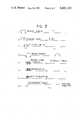
- FIG. 3shows a timing diagram for the unit.
- FIG. 1shows a sensing head 10 having two sections 12 and 14. Each section has a respective projection 12a, 14a forming a space 16 within which a tube 18, for example of compressible plastic material, is placed.
- a rigid chamber of plastic or glass or other materialcan be used, if desired.
- the space between the projections 12a, 14bis selected so that there will be a tight fit for the tube and preferably the portion of the tube held between the two projections is flattened.
- ultrasonic energy coupling compounde.g. silicone grease
- each of the sections 12, 14has a respective ultrasonic transducer 22, 24 embedded therein.
- the transducerscan be for example, of any suitable piezoelectric material as is well known in the art, for example, PZT.
- each transducer 22,24has a electrode on each face and a lead is connected thereto, the leads being designated 26-1, 26-2 and 28-1, 28-2.
- the leadsprovide energy to or convey energy from the respectively connected transducer.
- the sensing head sectionsare preferably molded from a suitable material, for example, an epoxy.
- the transducers elements and the wiresare also molded within the head sections.
- the sections of the sensing headcan be molded as a one-piece unit with a common back support or as separate pieces and then mounted to a common support.
- transducer 22is the transmitter and transducer 24 is the receiver. That is, transducer 22 receives bursts of electrical energy and converts them into ultrasonic energy which is transmitted through the tube 18 toward the receiving transducer 24. If there is liquid in the tube, the energy is transmitted through the tube and received by the receiving transducer 24 which converts the ultrasonic energy into electrical energy which can be detected by a suitable electronic circuitry. If there is a discontinuity in the fluid stream in the tube, for example, an air bubble, then there is no signal received. For ease of description, the invention is described with respect to air bubbles in the fluid stream.
- the size of the transducersdetermine the size of the bubble which can be reliably detected. That is, the surface area of each piezoelectric element is made slightly larger than the minimum size bubble to be detected. Generally, the diameter of the bubble to be detected is about one half the wavelength of the crystal resonant frequency. The resonant frequency is a function of the active surface area of the element. If there is a bubble in the tube which is equal to or larger than the size of the transducer, then there will be no signal received by the receiving transducer 24.
- bursts of ultrasonic energyare transmitted at a rate which is substantially greater than the flow rate of the bubbles in the tube so that any stoppage of transmission of the energy through the tube, caused by the presence of an air bubble, is reliably detected.
- the circuitry of the systemincludes a clock pulse generator 30 which produces bursts of ultrasonic energy in the form of rectangular clock pulses at a desired frequency, and for a predetermine period of time.
- Typical frequencies, for the pulses which have been found to work successfullyare in the range of about 3 Mhz to about 5 Mhz. Other frequencies can be used depending upon the type of liquid to be sensed, the type of tube, the diameter of the tube, etc. While these frequencies may also be considered to be in the low radio frequency range, they are also considered to be ultrasonic in the sense that they are of higher frequency than sound waves and it is the mechanical properties of the energy which is relied upon for transmission through the liquid rather than the electromagnetic properties.
- the piezoelectric transducer elements 22, 24are cut to be resonant at or near the frequency of the pulses from the pulse generator 30.
- the clock pulse generator 30can be on continuously and its pulses are supplied to transducer 22 through an AND gate 31 which is gated open for a predetermined time period by a suitable controller, for example a monostable, self-triggering, one-shot multivibrator circuit 32 which produces an enable signal for a transmit time window.
- the on time period for the clock pulse generatoris from t 0 to t 2 as shown on line a of FIG. 3 during which the clock pulses are provided to the transducer 22 for transmission through the tube 18.
- the duration of the transmit windowis selected based upon a variety of factors such as minimum bubble size and flow rate.
- the window time and repetition rateshould be such that at least several bursts of energy will pass through a minimum size bubble as it passes across the transducer surface.
- the clock pulsesare shown on line b. It should be understood that many more pulses than those shown are produced during this period.
- the one-shot multivibrator 32is set to have an off period, as shown on line a of FIG. 3 from t 2 back to t 0 of the next cycle.
- AND gate 31is closed and no clock pulses are supplied to the transducer 22.
- the receiving transducer 24is available to listen for received signals which are transmitted through the tube and processing of the received signals is taking place.
- the signal from its outputis applied to the input of a triggered delay multivibrator 34 to cause it to change its state.
- the delay multivibrator 34produces a predetermined delay inhibit period from t 2 to t 3 (see line c of FIG. 3) which corresponds to the time it takes to transmit pulses through the tube, i.e. corresponds to the tube diameter or overall width for the frequency of the pulses transmitted. This time is known by virtue of knowledge of the tube diameter, liquid flowing in the tube and pulse frequency.
- the output of the delay flip-flop 34when it changes state, turns on a suitable time control circuit such as a one-shot 36 at t 3 to produce a receive window enable signal on line 37 from t 3 to t 4 (see line d of FIG. 3). That is, when one-shot 36 is in its first state a disable (no receive) signal is produced on its output line 37 and when in a second state as shown on line d an enable (receive signal) is produced on line 37.
- a suitable time control circuitsuch as a one-shot 36 at t 3 to produce a receive window enable signal on line 37 from t 3 to t 4 (see line d of FIG. 3). That is, when one-shot 36 is in its first state a disable (no receive) signal is produced on its output line 37 and when in a second state as shown on line d an enable (receive signal) is produced on line 37.
- Signals received by transducer 24 from transducer 22 which are transmitted through the tube 16 when a liquid is present in the tubeare converted from acoustic energy into an analog RF signal by the transducer 24.
- These signalsare applied to the input of an amplifier 43 which can be any conventional analog amplifier, preferably of the wide band type.
- the output of the amplifier 43is applied to a threshold detector 45 which operates to pass a signal only above a predetermined threshold level. This prevents noise from entering the remainder of the signal processing circuit. That is, the threshold detector is set above the level of noise in the system so that noise will not trigger the system into producing one type of an indication or another.
- Line e of FIG. 3shows the received signal which occurs during the receive window period t 3 to t 4 if a liquid is present in the tube. If there is an air bubble, then no signal is received.
- the output of the threshold detector 45is applied to a digitizer 47.
- Thisis a conventional circuit, which can also include the threshold detector 45, and the digitizer has a pulse shaping, or squaring, circuit.
- the squaring circuitsquares the received signal into pulses which can be processed and counted.
- the output of the digitizerwhich is shown on line f of FIG. 3 is applied to a gate, or AND, circuit 49 whose other input is from line 37.
- the gate 49is opened only during the receive window period t 3 to t 4 .
- a valid digitizer output signal which occurs during the receive window periodis shown on line g. If an air bubble was in the tube at the time the burst of pulses was transmitted, then there would be no signal received during the receive window period.
- bursts of energyare transmitted at a relatively high rate which corresponds to the flow rate in the tube, that is, there are a large number of bursts transmitted, say four or more, during the time that a single bubble would be passing across the active surface area of the transducers 22, 24. This provides a number of cycles of transmitted and received signals so that signal processing can be performed to ensure a more reliable operation for the system than if merely amplitude level detection were utilized.
- the circuitperforms signal processing to discriminate against false alarms, i.e. providing a signal that a bubble is present when it is not, or vice versa. This is done by a signal processing technique which produces an output signal indicating the presence of a bubble only after the absence of a received signal through the liquid of the tube has been confirmed for a predetermined number of times. It should be understood that the normal condition for the system is that liquid is flowing through the tube and there are received pulses during the receive window time.
- the signals received by element 24are converted to pulses by the digitizer 47 and are passed through the AND gate 49 during the receive window time. These pulses may be provided to a divider-counter (not shown) which would produce an output pulse for a predetermined arbitrary number of input pulses from digitizer. The division ratio would be selected as a function of the frequency of the transmitted signal and the time duration of signal averaging desired. The divider counter may or may not be necessary as determined by such factors as tube diameter.
- the output pulses of the digitizer 47are applied to an overflow type counter 54.
- This counteris set to produce an output signal after receiving a predetermined number of pulses at its input from digitizer 47. This output signal will be retained for all subsequent input signals until the counter 54 is reset to zero.
- the overflow countcan be that which is equal to the pulses received from the digitizer 47 after there has been a number, say 10 or more, of bursts of energy transmitted through the tube 18. Thus, it takes 10 or more confirmations of the liquid being present in the tube before the overflow counter 54 produces an output signal.
- the output signal from overflow counter 54is applied to the set(S) input of flip-flop 56.
- the flip-flopWhen the flip-flop is set, it produces an output signal which is used to control some type of an indicator or a control element, such as a relay (not shown).
- a relayIn a preferred embodiment of the invention, an LED 62 is connected to the flip-flop output through an inverter 61. With this arrangement, the LED will be “off” when there is liquid in the tube and "on" when there is a bubble.
- power amplifierscan be located between the flip-flop output and the relay. The relay can be either energized or deenergized in the presence of a liquid or vice versus depending upon the control function to be performed.
- control counter 65which is also of the overflow type. Counter 65 increments its count by one each time there is a burst of transmitted energy. This is done in response to the firing of the multivibrator 36 which sets the receive window.
- the control counter 65has a reset input which is connected to the output of the AND gate 49 which receives the pulses from digitizer 47. The output of control counter 65 is applied to the reset input of the flip-flop 56. If a signal is being received by the transducer 24, indicating that there is liquid flowing in tube 18, then control counter 65 is reset each time digitizer 47 produces an output signal. In this case, the control counter 65 produces no output signal and the state of the flip-flop 64 is left set, i.e., there is liquid in the tube.
- control counter 65If there is no liquid in the tube, that is, there is a bubble, then the digitizer 47 will not produce a reset signal for control counter 65.
- the count of control counter 65will now be incremented by one each time there is a burst of energy transmitted and it will continue to increment until its overflow count level is reached. At this time it produces an output signal which resets the flip-flop 56.
- the count needed to cause control counter 65 to produce an outputcan be set to a relatively low level, for example, 1, 2, 4, or more.
- the countis set to four, four bursts of pulses which produce no output at the digitizer 47 because there is no liquid, i.e. there is a bubble, will cause the control counter 65 to produce an output signal which will change (to reset) the state of the flip-flop 56.
- the LED 62lights to indicate the presence of a bubble.
- control counter 65When control counter 65 produces an output signal, it is used to reset counter 54 so that it can start to increment from a zero level once the digitizer 47 produces output pulses in response to the re-occurrence of a liquid in the tube. When the bubble passes and the digitizer 47 again starts to produce output pulses, the counter 54 overflows to change the state of flip-flop 56 to the set condition and the LED 62 goes off.
- the overflow count for counter 54can be set for any desired number of pulses, say, for example, about half or more of those present during one transmit burst.
- control counter 65is not reset and is kept in the overflow state by the signal from multivibrator 36 at each transmit cycle. This keeps flip-flop 56 reset.
- the digitizer 47produces pulses which reset control counter 65 and keep it from incrementing.
- the flip-flop 56will temporarily stay in the reset condition, but after a short time the counter 54 will be overflowed so that it produces a signal to set the flip-flop 56 to indicate the presence of a liquid in the tube.
- control counter 65By selecting the number of bursts of no received signals which are needed to trigger the control counter 65, the sensitivity of the detecting system can be set. As previously explained, this is a function of the fluid flow rate through the tube, the rate at which the transmit windows are produced for the clock pulses and other factors. For maximum sensitivity, control counter 65 can be set to produce an output pulse, and thus change the state of the flip-flop, in response to one cycle when no signals are being produced by the digitizer 47.
- the systemhas been described with respect to detecting air bubbles in a fluid stream, it should be understood that it can also detect solid particles or two different liquids, e.g. drops of slugs of oil or water flowing in a stream of a different liquid, drops of liquid in a gas, etc.
- solid particles, the drops of liquid in a gas stream, and a liquid different from the main onehave different transmission characteristics to the ultrasonic energy, this will result in different amplitudes of signals being received by the transducer 24.
- the threshold detector 45therefore can be set to distinquish between the amplitudes of signals from the two different types of materials flowing in the tube. That is, one level would be passed to the digitizer 47 and the other would not. The ones not passed correspond to the air bubbles are previously described.
- discontinuityis used to encompass any such air bubble, particle, different type of liquid, etc.
Landscapes
- Health & Medical Sciences (AREA)
- Physics & Mathematics (AREA)
- General Health & Medical Sciences (AREA)
- Life Sciences & Earth Sciences (AREA)
- Biochemistry (AREA)
- Immunology (AREA)
- General Physics & Mathematics (AREA)
- Pathology (AREA)
- Analytical Chemistry (AREA)
- Chemical & Material Sciences (AREA)
- Engineering & Computer Science (AREA)
- Heart & Thoracic Surgery (AREA)
- Vascular Medicine (AREA)
- Biomedical Technology (AREA)
- Acoustics & Sound (AREA)
- Veterinary Medicine (AREA)
- Public Health (AREA)
- Animal Behavior & Ethology (AREA)
- Hematology (AREA)
- Anesthesiology (AREA)
- Cardiology (AREA)
- Probability & Statistics with Applications (AREA)
- Signal Processing (AREA)
- Investigating Or Analyzing Materials By The Use Of Ultrasonic Waves (AREA)
- Infusion, Injection, And Reservoir Apparatuses (AREA)
Abstract
Description
Claims (15)
Priority Applications (1)
| Application Number | Priority Date | Filing Date | Title |
|---|---|---|---|
| US06/569,389US4607520A (en) | 1984-01-09 | 1984-01-09 | Method and apparatus for detecting discontinuities in a fluid stream |
Applications Claiming Priority (1)
| Application Number | Priority Date | Filing Date | Title |
|---|---|---|---|
| US06/569,389US4607520A (en) | 1984-01-09 | 1984-01-09 | Method and apparatus for detecting discontinuities in a fluid stream |
Publications (1)
| Publication Number | Publication Date |
|---|---|
| US4607520Atrue US4607520A (en) | 1986-08-26 |
Family
ID=24275255
Family Applications (1)
| Application Number | Title | Priority Date | Filing Date |
|---|---|---|---|
| US06/569,389Expired - LifetimeUS4607520A (en) | 1984-01-09 | 1984-01-09 | Method and apparatus for detecting discontinuities in a fluid stream |
Country Status (1)
| Country | Link |
|---|---|
| US (1) | US4607520A (en) |
Cited By (82)
| Publication number | Priority date | Publication date | Assignee | Title |
|---|---|---|---|---|
| US4673927A (en)* | 1984-10-31 | 1987-06-16 | Hospal A.G. | Apparatus for detecting and controlling the level of a gaseous fluid |
| US4696191A (en)* | 1986-06-24 | 1987-09-29 | The United States Of America As Represented By The United States Department Of Energy | Apparatus and method for void/particulate detection |
| EP0306130A1 (en)* | 1987-08-17 | 1989-03-08 | Imed Corporation | Ultrasonic detector |
| US4882928A (en)* | 1987-12-22 | 1989-11-28 | Lane Jr William E | Refrigeration efficiency monitoring system |
| US4958524A (en)* | 1988-05-10 | 1990-09-25 | Timothy Bonner | Flow meter |
| US5026348A (en)* | 1988-06-06 | 1991-06-25 | The General Hospital Corporation | Apparatus and method for the detection of IV catheter obstruction and extravasation |
| WO1991016087A1 (en)* | 1990-04-26 | 1991-10-31 | Infurex Ag | Process and device for detecting gas bubbles in ducts filled with liquid, in particular flexible, tubular ducts or containers |
| US5123275A (en)* | 1990-12-07 | 1992-06-23 | Ivac Corporation | Air in-line sensor system |
| US5177993A (en)* | 1991-07-22 | 1993-01-12 | Ivac Corporation | Air-in-line sensor |
| US5191795A (en)* | 1987-05-01 | 1993-03-09 | Abbott Laboratories | Ultrasonic detector |
| US5205153A (en)* | 1992-01-23 | 1993-04-27 | Cobe Laboratories, Inc. | Method and apparatus for detection of air bubbles in tubing |
| WO1994024526A1 (en)* | 1993-04-22 | 1994-10-27 | Max-Planck-Gesellschaft zur Förderung der Wissenschaften e.V., Berlin | Ultrasonic measurement equipment with at least one non-piezoelectric resonator chamber body and outer electroacoustic transducers |
| DE4326765A1 (en)* | 1993-05-19 | 1994-11-24 | Gerd Dipl Ing Flueh | Method for recognizing foreign bodies in liquid or solid masses and device for carrying out the method |
| US5385050A (en)* | 1992-04-07 | 1995-01-31 | Northrop Grumman Corporation | Gap measurement for shim manufacture |
| US5394732A (en)* | 1993-09-10 | 1995-03-07 | Cobe Laboratories, Inc. | Method and apparatus for ultrasonic detection of air bubbles |
| US5470604A (en)* | 1993-04-08 | 1995-11-28 | Chartered Semiconductor Manufacturing Pte Ltd. | Apparatus and method for spreading resist on a wafer and detecting bubbles in the resist |
| US5591916A (en)* | 1992-02-10 | 1997-01-07 | Byrne; Frederick N. | Foreign object detector for vehicles and other machinery |
| US5633462A (en)* | 1994-07-19 | 1997-05-27 | Apa Systems | Method and apparatus for detecting the condition of the flow of liquid metal in and from a teeming vessel |
| US5668326A (en)* | 1996-10-04 | 1997-09-16 | Dieterich Technology Holding Corp. | Method and apparatus for detecting and aligning a signal |
| US5723773A (en)* | 1995-12-06 | 1998-03-03 | Eastman Kodak Company | Bubble detector |
| WO1998040733A1 (en)* | 1997-03-10 | 1998-09-17 | Amersham Pharmacia Biotech Ab | Apparatus for detection of inhomogeneities in a liquid flow |
| US5960129A (en)* | 1997-12-22 | 1999-09-28 | Bayer Corporation | Method and apparatus for detecting liquid and gas segment flow through a tube |
| US5974863A (en)* | 1995-10-16 | 1999-11-02 | Persson; Lars-Anders | Method and device for liquid leakage indication |
| US6142008A (en)* | 1998-06-12 | 2000-11-07 | Abbott Laboratories | Air bubble sensor |
| US6223588B1 (en)* | 1997-04-05 | 2001-05-01 | Heriot-Watt University | Dew point and bubble point measurement |
| US6231320B1 (en) | 1998-06-12 | 2001-05-15 | Abbott Laboratories | Drug infusion pumping cassette latching mechanism |
| US6408679B1 (en)* | 2000-02-04 | 2002-06-25 | The United States Of America As Represented By The Administrator Of The National Aeronautics And Space Administration | Bubble measuring instrument and method |
| US6515487B1 (en)* | 2000-08-23 | 2003-02-04 | Magnetrol International, Inc. | Low voltage low current bubble detection circuit |
| US6539805B2 (en) | 1994-07-19 | 2003-04-01 | Vesuvius Crucible Company | Liquid metal flow condition detection |
| US6595035B1 (en)* | 2000-05-05 | 2003-07-22 | Jesco Products Company, Inc. | Sealant stream anomaly detecting assembly |
| US6616633B1 (en) | 1997-09-19 | 2003-09-09 | Alaris Medical Systems, Inc. | Apparatus and method for air-in-line detection |
| US20040197223A1 (en)* | 2003-01-14 | 2004-10-07 | Olsen Robert W. | Active air removal system operating modes of an extracorporeal blood circuit |
| US20040195178A1 (en)* | 2003-01-14 | 2004-10-07 | Carpenter Walter L. | Extracorporeal blood circuit priming system and method |
| US20040217054A1 (en)* | 2003-01-14 | 2004-11-04 | Olsen Robert W. | Extracorporeal blood circuit air removal system and method |
| US20040220509A1 (en)* | 2003-01-14 | 2004-11-04 | Olsen Robert W. | Active air removal from an extracorporeal blood circuit |
| US20050063860A1 (en)* | 2003-01-14 | 2005-03-24 | Carpenter Walter L. | Disposable, integrated, extracorporeal blood circuit |
| US20060276748A1 (en)* | 2005-05-17 | 2006-12-07 | Infussafe Llc | Infusion monitoring device system and method |
| WO2006128683A1 (en)* | 2005-06-03 | 2006-12-07 | Fresenius Medical Care Deutschland Gmbh | Method and device for monitoring a flow of liquid for the presence of air by means of ultrasound |
| WO2007080618A3 (en)* | 2006-01-11 | 2007-09-20 | M P I S P A Sa | Method and instrument for detecting air and/or other gases inside transiting liquids |
| US20080189067A1 (en)* | 2005-05-27 | 2008-08-07 | Micro Motion, Inc. | Methods and Meter Electronics for Rapidly Detecting a Non-Uniformity of a Material Flowing Through a Coriolis Flowmeter |
| US20090088687A1 (en)* | 2007-10-01 | 2009-04-02 | Baxter International Inc. | Medical fluid air bubble detection apparatus and method |
| WO2012128816A2 (en) | 2010-12-29 | 2012-09-27 | Baxter International Inc. | Intravenous pumping air management systems and methods |
| US8363208B2 (en) | 2003-06-11 | 2013-01-29 | Asml Netherlands B.V. | Lithographic apparatus and device manufacturing method |
| US20130091953A1 (en)* | 2011-10-17 | 2013-04-18 | Houston Brown | Air in line detector with loading enhancements |
| US20130283929A1 (en)* | 2012-04-26 | 2013-10-31 | Tokyo Electron Limited | Solution processing apparatus, solution processing method, and non-transitory computer-readable recording medium |
| US8770010B1 (en) | 2009-03-30 | 2014-07-08 | Strain Measurement Devices, Inc. | Integrated detector for detecting bubbles in fluid flow and occlusions in a tube |
| US8801656B2 (en) | 2012-10-29 | 2014-08-12 | Hospira, Inc. | Fluid flow passage to improve air-in-line detection |
| US8857269B2 (en) | 2010-08-05 | 2014-10-14 | Hospira, Inc. | Method of varying the flow rate of fluid from a medical pump and hybrid sensor system performing the same |
| CN104634869A (en)* | 2010-12-09 | 2015-05-20 | 株式会社东芝 | Foreign object detection device and droplet discharging device |
| CN105983148A (en)* | 2015-03-17 | 2016-10-05 | B·布莱恩·阿维图姆股份公司 | Gas bubble and/or solid object detector based on ultrasound, dialysis device and method for such a detector |
| EP3003442A4 (en)* | 2013-05-29 | 2016-12-14 | Hospira Inc | INFUSION SYSTEM AND METHOD OF USE PREVENTING SURSATURATION OF AN ANALOGUE-DIGITAL CONVERTER |
| US20170315098A1 (en)* | 2016-04-29 | 2017-11-02 | David F. Beers | Ultrasonic contaminant detection system |
| US9995611B2 (en) | 2012-03-30 | 2018-06-12 | Icu Medical, Inc. | Air detection system and method for detecting air in a pump of an infusion system |
| US10022498B2 (en) | 2011-12-16 | 2018-07-17 | Icu Medical, Inc. | System for monitoring and delivering medication to a patient and method of using the same to minimize the risks associated with automated therapy |
| US10046112B2 (en) | 2013-05-24 | 2018-08-14 | Icu Medical, Inc. | Multi-sensor infusion system for detecting air or an occlusion in the infusion system |
| US10143795B2 (en) | 2014-08-18 | 2018-12-04 | Icu Medical, Inc. | Intravenous pole integrated power, control, and communication system and method for an infusion pump |
| US10166328B2 (en) | 2013-05-29 | 2019-01-01 | Icu Medical, Inc. | Infusion system which utilizes one or more sensors and additional information to make an air determination regarding the infusion system |
| CN109716123A (en)* | 2016-09-15 | 2019-05-03 | 株式会社Jms | Supersonic sensing head and supersonic detector with the supersonic sensing head |
| US10342917B2 (en) | 2014-02-28 | 2019-07-09 | Icu Medical, Inc. | Infusion system and method which utilizes dual wavelength optical air-in-line detection |
| US10430761B2 (en) | 2011-08-19 | 2019-10-01 | Icu Medical, Inc. | Systems and methods for a graphical interface including a graphical representation of medical data |
| US10463788B2 (en) | 2012-07-31 | 2019-11-05 | Icu Medical, Inc. | Patient care system for critical medications |
| US10635784B2 (en) | 2007-12-18 | 2020-04-28 | Icu Medical, Inc. | User interface improvements for medical devices |
| US10656894B2 (en) | 2017-12-27 | 2020-05-19 | Icu Medical, Inc. | Synchronized display of screen content on networked devices |
| US10850024B2 (en) | 2015-03-02 | 2020-12-01 | Icu Medical, Inc. | Infusion system, device, and method having advanced infusion features |
| US10918787B2 (en) | 2015-05-26 | 2021-02-16 | Icu Medical, Inc. | Disposable infusion fluid delivery device for programmable large volume drug delivery |
| US11135360B1 (en) | 2020-12-07 | 2021-10-05 | Icu Medical, Inc. | Concurrent infusion with common line auto flush |
| USD939079S1 (en) | 2019-08-22 | 2021-12-21 | Icu Medical, Inc. | Infusion pump |
| US11213619B2 (en) | 2013-11-11 | 2022-01-04 | Icu Medical, Inc. | Thermal management system and method for medical devices |
| US20220001090A1 (en)* | 2020-07-02 | 2022-01-06 | Awe Technologies Llc | System and method for detecting venous needle dislodgement |
| US11246985B2 (en) | 2016-05-13 | 2022-02-15 | Icu Medical, Inc. | Infusion pump system and method with common line auto flush |
| US11278671B2 (en) | 2019-12-04 | 2022-03-22 | Icu Medical, Inc. | Infusion pump with safety sequence keypad |
| US11324888B2 (en) | 2016-06-10 | 2022-05-10 | Icu Medical, Inc. | Acoustic flow sensor for continuous medication flow measurements and feedback control of infusion |
| US11344668B2 (en) | 2014-12-19 | 2022-05-31 | Icu Medical, Inc. | Infusion system with concurrent TPN/insulin infusion |
| US11344673B2 (en) | 2014-05-29 | 2022-05-31 | Icu Medical, Inc. | Infusion system and pump with configurable closed loop delivery rate catch-up |
| US20230211570A1 (en)* | 2022-01-05 | 2023-07-06 | The Boeing Company | Methods and systems for inspecting bonded structures |
| US11883361B2 (en) | 2020-07-21 | 2024-01-30 | Icu Medical, Inc. | Fluid transfer devices and methods of use |
| US20240082511A1 (en)* | 2021-06-23 | 2024-03-14 | Honeywell International Inc. | Fluid flow system for bubble and fluid detection |
| USD1052728S1 (en) | 2021-11-12 | 2024-11-26 | Icu Medical, Inc. | Medical fluid infusion pump |
| DE102023126813A1 (en)* | 2023-10-02 | 2025-04-03 | B.Braun Avitum Ag | Air bubble detector for a medical device |
| US12350233B2 (en) | 2021-12-10 | 2025-07-08 | Icu Medical, Inc. | Medical fluid compounding systems with coordinated flow control |
| US12390571B2 (en) | 2023-10-27 | 2025-08-19 | Awe Technologies Llc | Needle dislodgement detection systems and methods |
| USD1091564S1 (en) | 2021-10-13 | 2025-09-02 | Icu Medical, Inc. | Display screen or portion thereof with graphical user interface for a medical device |
Citations (26)
| Publication number | Priority date | Publication date | Assignee | Title |
|---|---|---|---|---|
| US2949769A (en)* | 1956-01-20 | 1960-08-23 | Curtiss Wright Corp | Self-balancing ultrasonic instrument |
| US2966056A (en)* | 1956-01-20 | 1960-12-27 | Curtiss Wright Corp | Ultrasonic testing device |
| US2966057A (en)* | 1956-04-30 | 1960-12-27 | Curtiss Wright Corp | Apparatus for measuring attenuation of ultrasonic energy |
| GB968561A (en)* | 1961-06-12 | 1964-09-02 | Chesapeake Instr Corp | Electro-acoustic measuring apparatus |
| US3392574A (en)* | 1966-06-13 | 1968-07-16 | Chesapeake Instr Corp | Sing-around velocimeter |
| US3623363A (en)* | 1969-03-06 | 1971-11-30 | Realisations Ultrasoniques Sa | Ultrasonic flowmeter |
| US3710621A (en)* | 1970-02-10 | 1973-01-16 | Tokyo Keiki Kk | Sing-around type ultrasonic measuring instrument |
| US3859846A (en)* | 1971-12-26 | 1975-01-14 | Tokyo Keikio Tokyo Keiki Co Lt | Ultrasonic interface meter |
| US3881353A (en)* | 1974-04-29 | 1975-05-06 | Dickey John Corp | Ultrasonic sensor |
| US3914984A (en)* | 1972-05-08 | 1975-10-28 | Richard A Wade | System for measuring solids and/or immiscible liquids in liquids |
| US3921622A (en)* | 1973-02-27 | 1975-11-25 | Edward Michael Cole | Method and apparatus for ultrasonic detection of inclusions in a flowing fluid |
| US3977252A (en)* | 1974-11-21 | 1976-08-31 | Eleonora Dmitrievna Krylova | Method and apparatus for controlling liquid pressure in pipelines |
| US4015464A (en)* | 1975-02-21 | 1977-04-05 | The Washington University | Ultrasonic continuous wave particle monitor |
| US4015470A (en)* | 1973-12-26 | 1977-04-05 | Trw Inc. | Flow measuring method and apparatus |
| US4022058A (en)* | 1975-08-07 | 1977-05-10 | Brown Alvin E | Apparatus for determining the arrival time of alternating signals |
| US4065958A (en)* | 1976-10-18 | 1978-01-03 | Eleonora Dmitrievna Krylova | Method of controlling physical characteristics of fluid medium |
| US4095457A (en)* | 1976-07-16 | 1978-06-20 | Nippon Kokan Kabushiki Kaisha | Apparatus for detecting changes in parameters of liquid flowing in a pipe based on sing-around method |
| US4138879A (en)* | 1977-08-22 | 1979-02-13 | Tif Instruments, Inc. | Sightless bubble detector |
| US4235095A (en)* | 1978-09-01 | 1980-11-25 | Tif Instruments, Inc. | Device for detecting inhomogeneities such as gas bubbles |
| US4339944A (en)* | 1980-05-21 | 1982-07-20 | Micro Pure Systems, Inc. | Ultrasonic particulate identification |
| US4345479A (en)* | 1981-01-13 | 1982-08-24 | The Perkin-Elmer Corporation | Flowmeter system with synchronous clock for generation of timing signals |
| US4347747A (en)* | 1981-01-12 | 1982-09-07 | Shell Oil Company | Single phase flow measurement |
| US4446744A (en)* | 1981-01-23 | 1984-05-08 | Itt Industries, Incorporated | Ultrasonic flowmeter |
| US4468971A (en)* | 1982-07-16 | 1984-09-04 | Fischer And Porter Company | Ultrasonic flowmeter for clean and dirty fluids |
| US4478072A (en)* | 1981-10-09 | 1984-10-23 | The British Petroleum Company P.L.C. | Apparatus for determining the concentration of solids dispersed in a liquid |
| US4480485A (en)* | 1982-10-01 | 1984-11-06 | Panametrics, Inc. | Acoustic flowmeter with envelope midpoint tracking |
- 1984
- 1984-01-09USUS06/569,389patent/US4607520A/ennot_activeExpired - Lifetime
Patent Citations (26)
| Publication number | Priority date | Publication date | Assignee | Title |
|---|---|---|---|---|
| US2949769A (en)* | 1956-01-20 | 1960-08-23 | Curtiss Wright Corp | Self-balancing ultrasonic instrument |
| US2966056A (en)* | 1956-01-20 | 1960-12-27 | Curtiss Wright Corp | Ultrasonic testing device |
| US2966057A (en)* | 1956-04-30 | 1960-12-27 | Curtiss Wright Corp | Apparatus for measuring attenuation of ultrasonic energy |
| GB968561A (en)* | 1961-06-12 | 1964-09-02 | Chesapeake Instr Corp | Electro-acoustic measuring apparatus |
| US3392574A (en)* | 1966-06-13 | 1968-07-16 | Chesapeake Instr Corp | Sing-around velocimeter |
| US3623363A (en)* | 1969-03-06 | 1971-11-30 | Realisations Ultrasoniques Sa | Ultrasonic flowmeter |
| US3710621A (en)* | 1970-02-10 | 1973-01-16 | Tokyo Keiki Kk | Sing-around type ultrasonic measuring instrument |
| US3859846A (en)* | 1971-12-26 | 1975-01-14 | Tokyo Keikio Tokyo Keiki Co Lt | Ultrasonic interface meter |
| US3914984A (en)* | 1972-05-08 | 1975-10-28 | Richard A Wade | System for measuring solids and/or immiscible liquids in liquids |
| US3921622A (en)* | 1973-02-27 | 1975-11-25 | Edward Michael Cole | Method and apparatus for ultrasonic detection of inclusions in a flowing fluid |
| US4015470A (en)* | 1973-12-26 | 1977-04-05 | Trw Inc. | Flow measuring method and apparatus |
| US3881353A (en)* | 1974-04-29 | 1975-05-06 | Dickey John Corp | Ultrasonic sensor |
| US3977252A (en)* | 1974-11-21 | 1976-08-31 | Eleonora Dmitrievna Krylova | Method and apparatus for controlling liquid pressure in pipelines |
| US4015464A (en)* | 1975-02-21 | 1977-04-05 | The Washington University | Ultrasonic continuous wave particle monitor |
| US4022058A (en)* | 1975-08-07 | 1977-05-10 | Brown Alvin E | Apparatus for determining the arrival time of alternating signals |
| US4095457A (en)* | 1976-07-16 | 1978-06-20 | Nippon Kokan Kabushiki Kaisha | Apparatus for detecting changes in parameters of liquid flowing in a pipe based on sing-around method |
| US4065958A (en)* | 1976-10-18 | 1978-01-03 | Eleonora Dmitrievna Krylova | Method of controlling physical characteristics of fluid medium |
| US4138879A (en)* | 1977-08-22 | 1979-02-13 | Tif Instruments, Inc. | Sightless bubble detector |
| US4235095A (en)* | 1978-09-01 | 1980-11-25 | Tif Instruments, Inc. | Device for detecting inhomogeneities such as gas bubbles |
| US4339944A (en)* | 1980-05-21 | 1982-07-20 | Micro Pure Systems, Inc. | Ultrasonic particulate identification |
| US4347747A (en)* | 1981-01-12 | 1982-09-07 | Shell Oil Company | Single phase flow measurement |
| US4345479A (en)* | 1981-01-13 | 1982-08-24 | The Perkin-Elmer Corporation | Flowmeter system with synchronous clock for generation of timing signals |
| US4446744A (en)* | 1981-01-23 | 1984-05-08 | Itt Industries, Incorporated | Ultrasonic flowmeter |
| US4478072A (en)* | 1981-10-09 | 1984-10-23 | The British Petroleum Company P.L.C. | Apparatus for determining the concentration of solids dispersed in a liquid |
| US4468971A (en)* | 1982-07-16 | 1984-09-04 | Fischer And Porter Company | Ultrasonic flowmeter for clean and dirty fluids |
| US4480485A (en)* | 1982-10-01 | 1984-11-06 | Panametrics, Inc. | Acoustic flowmeter with envelope midpoint tracking |
Cited By (150)
| Publication number | Priority date | Publication date | Assignee | Title |
|---|---|---|---|---|
| US4673927A (en)* | 1984-10-31 | 1987-06-16 | Hospal A.G. | Apparatus for detecting and controlling the level of a gaseous fluid |
| US4696191A (en)* | 1986-06-24 | 1987-09-29 | The United States Of America As Represented By The United States Department Of Energy | Apparatus and method for void/particulate detection |
| US5191795A (en)* | 1987-05-01 | 1993-03-09 | Abbott Laboratories | Ultrasonic detector |
| EP0306130A1 (en)* | 1987-08-17 | 1989-03-08 | Imed Corporation | Ultrasonic detector |
| US4882928A (en)* | 1987-12-22 | 1989-11-28 | Lane Jr William E | Refrigeration efficiency monitoring system |
| US4958524A (en)* | 1988-05-10 | 1990-09-25 | Timothy Bonner | Flow meter |
| US5026348A (en)* | 1988-06-06 | 1991-06-25 | The General Hospital Corporation | Apparatus and method for the detection of IV catheter obstruction and extravasation |
| WO1991016087A1 (en)* | 1990-04-26 | 1991-10-31 | Infurex Ag | Process and device for detecting gas bubbles in ducts filled with liquid, in particular flexible, tubular ducts or containers |
| DE4013402A1 (en)* | 1990-04-26 | 1991-11-07 | Infurex Ag | METHOD AND DEVICE FOR DETECTING GAS BUBBLES IN LINES FILLED WITH LIQUID, IN PARTICULAR FLEXIBLE, TUBULAR-LIKE LINES OR CONTAINERS |
| US5123275A (en)* | 1990-12-07 | 1992-06-23 | Ivac Corporation | Air in-line sensor system |
| US5177993A (en)* | 1991-07-22 | 1993-01-12 | Ivac Corporation | Air-in-line sensor |
| US5205153A (en)* | 1992-01-23 | 1993-04-27 | Cobe Laboratories, Inc. | Method and apparatus for detection of air bubbles in tubing |
| WO1993015397A1 (en)* | 1992-01-23 | 1993-08-05 | Cobe Laboratories, Inc. | Method and apparatus for detection of air bubbles in tubing |
| US5591916A (en)* | 1992-02-10 | 1997-01-07 | Byrne; Frederick N. | Foreign object detector for vehicles and other machinery |
| US5385050A (en)* | 1992-04-07 | 1995-01-31 | Northrop Grumman Corporation | Gap measurement for shim manufacture |
| US5470604A (en)* | 1993-04-08 | 1995-11-28 | Chartered Semiconductor Manufacturing Pte Ltd. | Apparatus and method for spreading resist on a wafer and detecting bubbles in the resist |
| WO1994024526A1 (en)* | 1993-04-22 | 1994-10-27 | Max-Planck-Gesellschaft zur Förderung der Wissenschaften e.V., Berlin | Ultrasonic measurement equipment with at least one non-piezoelectric resonator chamber body and outer electroacoustic transducers |
| US5983723A (en)* | 1993-04-22 | 1999-11-16 | Vitaly Buckin | Ultrasonic measurement equipment with at least one non-piezoelectric resonator chamber body and outer electroacoustic transducers |
| DE4326765A1 (en)* | 1993-05-19 | 1994-11-24 | Gerd Dipl Ing Flueh | Method for recognizing foreign bodies in liquid or solid masses and device for carrying out the method |
| EP0643301A1 (en)* | 1993-09-10 | 1995-03-15 | Cobe Laboratories, Inc. | Method and apparatus for ultrasonic detection of air bubbles |
| US5394732A (en)* | 1993-09-10 | 1995-03-07 | Cobe Laboratories, Inc. | Method and apparatus for ultrasonic detection of air bubbles |
| EP1182452A3 (en)* | 1993-09-10 | 2005-03-16 | Gambro, Inc. | Method and apparatus for ultrasonic detection of air bubbles |
| US5633462A (en)* | 1994-07-19 | 1997-05-27 | Apa Systems | Method and apparatus for detecting the condition of the flow of liquid metal in and from a teeming vessel |
| US6539805B2 (en) | 1994-07-19 | 2003-04-01 | Vesuvius Crucible Company | Liquid metal flow condition detection |
| US5974863A (en)* | 1995-10-16 | 1999-11-02 | Persson; Lars-Anders | Method and device for liquid leakage indication |
| US5723773A (en)* | 1995-12-06 | 1998-03-03 | Eastman Kodak Company | Bubble detector |
| US5668326A (en)* | 1996-10-04 | 1997-09-16 | Dieterich Technology Holding Corp. | Method and apparatus for detecting and aligning a signal |
| WO1998014761A1 (en)* | 1996-10-04 | 1998-04-09 | Dieterich Technology Holding Corp. | Method and apparatus for detecting and aligning a signal |
| US6282949B1 (en)* | 1997-03-10 | 2001-09-04 | Amersham Pharmacia Biotech Ab | Apparatus for detection of inhomogeneities in a liquid flow |
| WO1998040733A1 (en)* | 1997-03-10 | 1998-09-17 | Amersham Pharmacia Biotech Ab | Apparatus for detection of inhomogeneities in a liquid flow |
| US6223588B1 (en)* | 1997-04-05 | 2001-05-01 | Heriot-Watt University | Dew point and bubble point measurement |
| US6616633B1 (en) | 1997-09-19 | 2003-09-09 | Alaris Medical Systems, Inc. | Apparatus and method for air-in-line detection |
| US8082112B2 (en) | 1997-09-19 | 2011-12-20 | Carefusion 303, Inc. | Apparatus and method for air-in-line detection |
| US20080208484A1 (en)* | 1997-09-19 | 2008-08-28 | Cardinal Health 303, Inc. | Apparatus and method for air-in-line detection |
| US7141037B2 (en) | 1997-09-19 | 2006-11-28 | Cardinal Health 303, Inc. | Apparatus and method for air-in-line detection |
| US20050192529A1 (en)* | 1997-09-19 | 2005-09-01 | Butterfield Robert D. | Apparatus and method for air-in-line detection |
| US5960129A (en)* | 1997-12-22 | 1999-09-28 | Bayer Corporation | Method and apparatus for detecting liquid and gas segment flow through a tube |
| US6231320B1 (en) | 1998-06-12 | 2001-05-15 | Abbott Laboratories | Drug infusion pumping cassette latching mechanism |
| US6142008A (en)* | 1998-06-12 | 2000-11-07 | Abbott Laboratories | Air bubble sensor |
| US6408679B1 (en)* | 2000-02-04 | 2002-06-25 | The United States Of America As Represented By The Administrator Of The National Aeronautics And Space Administration | Bubble measuring instrument and method |
| US6595035B1 (en)* | 2000-05-05 | 2003-07-22 | Jesco Products Company, Inc. | Sealant stream anomaly detecting assembly |
| US6515487B1 (en)* | 2000-08-23 | 2003-02-04 | Magnetrol International, Inc. | Low voltage low current bubble detection circuit |
| US7201870B2 (en) | 2003-01-14 | 2007-04-10 | Medtronic, Inc. | Active air removal system operating modes of an extracorporeal blood circuit |
| US7704455B2 (en) | 2003-01-14 | 2010-04-27 | Medtronic, Inc. | Active air removal system operating modes of an extracorporeal blood circuit |
| US20040195178A1 (en)* | 2003-01-14 | 2004-10-07 | Carpenter Walter L. | Extracorporeal blood circuit priming system and method |
| US7740800B2 (en)* | 2003-01-14 | 2010-06-22 | Medtronic, Inc. | Extracorporeal blood circuit air removal system and method |
| US7829018B2 (en) | 2003-01-14 | 2010-11-09 | Medtronic, Inc. | Active air removal from an extracorporeal blood circuit |
| US7189352B2 (en) | 2003-01-14 | 2007-03-13 | Medtronic, Inc. | Extracorporeal blood circuit priming system and method |
| US20040217054A1 (en)* | 2003-01-14 | 2004-11-04 | Olsen Robert W. | Extracorporeal blood circuit air removal system and method |
| US7198751B2 (en) | 2003-01-14 | 2007-04-03 | Medtronic, Inc. | Disposable, integrated, extracorporeal blood circuit |
| US7204958B2 (en)* | 2003-01-14 | 2007-04-17 | Medtronic, Inc. | Extracorporeal blood circuit air removal system and method |
| US20040197223A1 (en)* | 2003-01-14 | 2004-10-07 | Olsen Robert W. | Active air removal system operating modes of an extracorporeal blood circuit |
| US20070140898A1 (en)* | 2003-01-14 | 2007-06-21 | Olsen Robert W | Extracorporeal blood circuit air removal system and method |
| US20070140899A1 (en)* | 2003-01-14 | 2007-06-21 | Olsen Robert W | Active air removal system operating modes of an extracorporeal blood circuit |
| US20050063860A1 (en)* | 2003-01-14 | 2005-03-24 | Carpenter Walter L. | Disposable, integrated, extracorporeal blood circuit |
| US20070258856A1 (en)* | 2003-01-14 | 2007-11-08 | Olsen Robert W | Active air removal from an extracorporeal blood circuit |
| US7335334B2 (en) | 2003-01-14 | 2008-02-26 | Medtronic, Inc. | Active air removal from an extracorporeal blood circuit |
| US20040220509A1 (en)* | 2003-01-14 | 2004-11-04 | Olsen Robert W. | Active air removal from an extracorporeal blood circuit |
| US9110389B2 (en) | 2003-06-11 | 2015-08-18 | Asml Netherlands B.V. | Lithographic apparatus and device manufacturing method |
| US8363208B2 (en) | 2003-06-11 | 2013-01-29 | Asml Netherlands B.V. | Lithographic apparatus and device manufacturing method |
| US9964858B2 (en) | 2003-06-11 | 2018-05-08 | Asml Netherlands B.V. | Lithographic apparatus and device manufacturing method |
| JP2007515251A (en)* | 2003-12-22 | 2007-06-14 | メドトロニック・インコーポレーテッド | Extracorporeal blood circuit air removal system and method |
| US20060276748A1 (en)* | 2005-05-17 | 2006-12-07 | Infussafe Llc | Infusion monitoring device system and method |
| US20080189067A1 (en)* | 2005-05-27 | 2008-08-07 | Micro Motion, Inc. | Methods and Meter Electronics for Rapidly Detecting a Non-Uniformity of a Material Flowing Through a Coriolis Flowmeter |
| US7908097B2 (en)* | 2005-05-27 | 2011-03-15 | Micro Motion, Inc. | Methods and meter electronics for rapidly detecting a non-uniformity of a material flowing through a coriolis flowmeter |
| CN101189509B (en)* | 2005-06-03 | 2010-10-13 | 弗雷泽纽斯医疗保健德国有限公司 | Method and device for monitoring a liquid flow for the presence of air by means of ultrasound |
| US8091407B2 (en)* | 2005-06-03 | 2012-01-10 | Fresenius Medical Care Deutschland Gmbh | Method and device for monitoring a flow of liquid for the presence of air by means of ultrasound |
| US20080282804A1 (en)* | 2005-06-03 | 2008-11-20 | Jochen Schneider | Method and Device for Monitoring a Flow of Liquid for the Presence of Air by Means of Ultrasound |
| WO2006128683A1 (en)* | 2005-06-03 | 2006-12-07 | Fresenius Medical Care Deutschland Gmbh | Method and device for monitoring a flow of liquid for the presence of air by means of ultrasound |
| WO2007080618A3 (en)* | 2006-01-11 | 2007-09-20 | M P I S P A Sa | Method and instrument for detecting air and/or other gases inside transiting liquids |
| US8033157B2 (en)* | 2007-10-01 | 2011-10-11 | Baxter International Inc. | Medical fluid air bubble detection apparatus and method |
| US20090088687A1 (en)* | 2007-10-01 | 2009-04-02 | Baxter International Inc. | Medical fluid air bubble detection apparatus and method |
| US10635784B2 (en) | 2007-12-18 | 2020-04-28 | Icu Medical, Inc. | User interface improvements for medical devices |
| US8770010B1 (en) | 2009-03-30 | 2014-07-08 | Strain Measurement Devices, Inc. | Integrated detector for detecting bubbles in fluid flow and occlusions in a tube |
| US8857269B2 (en) | 2010-08-05 | 2014-10-14 | Hospira, Inc. | Method of varying the flow rate of fluid from a medical pump and hybrid sensor system performing the same |
| CN104634869B (en)* | 2010-12-09 | 2017-09-26 | 株式会社东芝 | Detection device for foreign matter and droplet ejection apparatus |
| CN104634869A (en)* | 2010-12-09 | 2015-05-20 | 株式会社东芝 | Foreign object detection device and droplet discharging device |
| WO2012128816A2 (en) | 2010-12-29 | 2012-09-27 | Baxter International Inc. | Intravenous pumping air management systems and methods |
| US11972395B2 (en) | 2011-08-19 | 2024-04-30 | Icu Medical, Inc. | Systems and methods for a graphical interface including a graphical representation of medical data |
| US11599854B2 (en) | 2011-08-19 | 2023-03-07 | Icu Medical, Inc. | Systems and methods for a graphical interface including a graphical representation of medical data |
| US11004035B2 (en) | 2011-08-19 | 2021-05-11 | Icu Medical, Inc. | Systems and methods for a graphical interface including a graphical representation of medical data |
| US10430761B2 (en) | 2011-08-19 | 2019-10-01 | Icu Medical, Inc. | Systems and methods for a graphical interface including a graphical representation of medical data |
| US12346879B2 (en) | 2011-08-19 | 2025-07-01 | Icu Medical, Inc. | Systems and methods for a graphical interface including a graphical representation of medical data |
| US20130091953A1 (en)* | 2011-10-17 | 2013-04-18 | Houston Brown | Air in line detector with loading enhancements |
| US10022498B2 (en) | 2011-12-16 | 2018-07-17 | Icu Medical, Inc. | System for monitoring and delivering medication to a patient and method of using the same to minimize the risks associated with automated therapy |
| US11376361B2 (en) | 2011-12-16 | 2022-07-05 | Icu Medical, Inc. | System for monitoring and delivering medication to a patient and method of using the same to minimize the risks associated with automated therapy |
| US9995611B2 (en) | 2012-03-30 | 2018-06-12 | Icu Medical, Inc. | Air detection system and method for detecting air in a pump of an infusion system |
| US11933650B2 (en) | 2012-03-30 | 2024-03-19 | Icu Medical, Inc. | Air detection system and method for detecting air in a pump of an infusion system |
| US10578474B2 (en) | 2012-03-30 | 2020-03-03 | Icu Medical, Inc. | Air detection system and method for detecting air in a pump of an infusion system |
| US9631963B2 (en) | 2012-04-26 | 2017-04-25 | Tokyo Electron Limited | Solution processing apparatus, solution processing method, and non-transitory computer-readable recording medium |
| US9109934B2 (en)* | 2012-04-26 | 2015-08-18 | Tokyo Electron Limited | Solution processing apparatus, solution processing method, and non-transitory computer-readable recording medium |
| US20130283929A1 (en)* | 2012-04-26 | 2013-10-31 | Tokyo Electron Limited | Solution processing apparatus, solution processing method, and non-transitory computer-readable recording medium |
| US11623042B2 (en) | 2012-07-31 | 2023-04-11 | Icu Medical, Inc. | Patient care system for critical medications |
| US12280239B2 (en) | 2012-07-31 | 2025-04-22 | Icu Medical, Inc. | Patient care system for critical medications |
| US10463788B2 (en) | 2012-07-31 | 2019-11-05 | Icu Medical, Inc. | Patient care system for critical medications |
| US8801656B2 (en) | 2012-10-29 | 2014-08-12 | Hospira, Inc. | Fluid flow passage to improve air-in-line detection |
| US10046112B2 (en) | 2013-05-24 | 2018-08-14 | Icu Medical, Inc. | Multi-sensor infusion system for detecting air or an occlusion in the infusion system |
| US10874793B2 (en) | 2013-05-24 | 2020-12-29 | Icu Medical, Inc. | Multi-sensor infusion system for detecting air or an occlusion in the infusion system |
| US12048831B2 (en) | 2013-05-24 | 2024-07-30 | Icu Medical, Inc. | Multi-sensor infusion system for detecting air or an occlusion in the infusion system |
| US10596316B2 (en) | 2013-05-29 | 2020-03-24 | Icu Medical, Inc. | Infusion system and method of use which prevents over-saturation of an analog-to-digital converter |
| US9707341B2 (en) | 2013-05-29 | 2017-07-18 | Icu Medical, Inc. | Infusion system and method of use which prevents over-saturation of an analog-to-digital converter |
| US12059551B2 (en) | 2013-05-29 | 2024-08-13 | Icu Medical, Inc. | Infusion system and method of use which prevents over-saturation of an analog-to-digital converter |
| AU2019204470B2 (en)* | 2013-05-29 | 2021-01-21 | Icu Medical, Inc | Infusion system and method of use which prevents over-saturation of an analog-to-digital converter |
| US10166328B2 (en) | 2013-05-29 | 2019-01-01 | Icu Medical, Inc. | Infusion system which utilizes one or more sensors and additional information to make an air determination regarding the infusion system |
| US11596737B2 (en) | 2013-05-29 | 2023-03-07 | Icu Medical, Inc. | Infusion system and method of use which prevents over-saturation of an analog-to-digital converter |
| EP3003442A4 (en)* | 2013-05-29 | 2016-12-14 | Hospira Inc | INFUSION SYSTEM AND METHOD OF USE PREVENTING SURSATURATION OF AN ANALOGUE-DIGITAL CONVERTER |
| US11433177B2 (en) | 2013-05-29 | 2022-09-06 | Icu Medical, Inc. | Infusion system which utilizes one or more sensors and additional information to make an air determination regarding the infusion system |
| US12076525B2 (en) | 2013-11-11 | 2024-09-03 | Icu Medical, Inc. | Thermal management system and method for medical devices |
| US11213619B2 (en) | 2013-11-11 | 2022-01-04 | Icu Medical, Inc. | Thermal management system and method for medical devices |
| US10342917B2 (en) | 2014-02-28 | 2019-07-09 | Icu Medical, Inc. | Infusion system and method which utilizes dual wavelength optical air-in-line detection |
| US12083310B2 (en) | 2014-02-28 | 2024-09-10 | Icu Medical, Inc. | Infusion system and method which utilizes dual wavelength optical air-in-line detection |
| US11344673B2 (en) | 2014-05-29 | 2022-05-31 | Icu Medical, Inc. | Infusion system and pump with configurable closed loop delivery rate catch-up |
| US10143795B2 (en) | 2014-08-18 | 2018-12-04 | Icu Medical, Inc. | Intravenous pole integrated power, control, and communication system and method for an infusion pump |
| US11344668B2 (en) | 2014-12-19 | 2022-05-31 | Icu Medical, Inc. | Infusion system with concurrent TPN/insulin infusion |
| US10850024B2 (en) | 2015-03-02 | 2020-12-01 | Icu Medical, Inc. | Infusion system, device, and method having advanced infusion features |
| US12115337B2 (en) | 2015-03-02 | 2024-10-15 | Icu Medical, Inc. | Infusion system, device, and method having advanced infusion features |
| CN105983148A (en)* | 2015-03-17 | 2016-10-05 | B·布莱恩·阿维图姆股份公司 | Gas bubble and/or solid object detector based on ultrasound, dialysis device and method for such a detector |
| US12156986B2 (en) | 2015-05-26 | 2024-12-03 | Icu Medical, Inc. | Disposable infusion fluid delivery device for programmable large volume drug delivery |
| US10918787B2 (en) | 2015-05-26 | 2021-02-16 | Icu Medical, Inc. | Disposable infusion fluid delivery device for programmable large volume drug delivery |
| US11660386B2 (en) | 2015-05-26 | 2023-05-30 | Icu Medical, Inc. | Disposable infusion fluid delivery device for programmable large volume drug delivery |
| US20170315098A1 (en)* | 2016-04-29 | 2017-11-02 | David F. Beers | Ultrasonic contaminant detection system |
| US10260466B2 (en)* | 2016-04-29 | 2019-04-16 | Progeny Systems Corporation | Ultrasonic contaminant detection system |
| US12201811B2 (en) | 2016-05-13 | 2025-01-21 | Icu Medical, Inc. | Infusion pump system and method with common line auto flush |
| US11246985B2 (en) | 2016-05-13 | 2022-02-15 | Icu Medical, Inc. | Infusion pump system and method with common line auto flush |
| US12076531B2 (en) | 2016-06-10 | 2024-09-03 | Icu Medical, Inc. | Acoustic flow sensor for continuous medication flow measurements and feedback control of infusion |
| US11324888B2 (en) | 2016-06-10 | 2022-05-10 | Icu Medical, Inc. | Acoustic flow sensor for continuous medication flow measurements and feedback control of infusion |
| CN109716123A (en)* | 2016-09-15 | 2019-05-03 | 株式会社Jms | Supersonic sensing head and supersonic detector with the supersonic sensing head |
| CN109716123B (en)* | 2016-09-15 | 2023-02-28 | 株式会社Jms | Ultrasonic sensing head and ultrasonic detector with same |
| US12333201B2 (en) | 2017-12-27 | 2025-06-17 | Icu Medical, Inc. | Synchronized display of screen content on networked devices |
| US11029911B2 (en) | 2017-12-27 | 2021-06-08 | Icu Medical, Inc. | Synchronized display of screen content on networked devices |
| US10656894B2 (en) | 2017-12-27 | 2020-05-19 | Icu Medical, Inc. | Synchronized display of screen content on networked devices |
| US11868161B2 (en) | 2017-12-27 | 2024-01-09 | Icu Medical, Inc. | Synchronized display of screen content on networked devices |
| USD1076062S1 (en) | 2019-08-22 | 2025-05-20 | Icu Medical, Inc. | Infusion pump |
| USD939079S1 (en) | 2019-08-22 | 2021-12-21 | Icu Medical, Inc. | Infusion pump |
| US12268843B2 (en) | 2019-12-04 | 2025-04-08 | Icu Medical, Inc. | Infusion pump with safety sequence keypad |
| US11278671B2 (en) | 2019-12-04 | 2022-03-22 | Icu Medical, Inc. | Infusion pump with safety sequence keypad |
| US12296083B2 (en)* | 2020-07-02 | 2025-05-13 | Awe Technologies Llc | System and method for detecting venous needle dislodgement |
| US20220001090A1 (en)* | 2020-07-02 | 2022-01-06 | Awe Technologies Llc | System and method for detecting venous needle dislodgement |
| US11883361B2 (en) | 2020-07-21 | 2024-01-30 | Icu Medical, Inc. | Fluid transfer devices and methods of use |
| US12310921B2 (en) | 2020-07-21 | 2025-05-27 | Icu Medical, Inc. | Fluid transfer devices and methods of use |
| US11135360B1 (en) | 2020-12-07 | 2021-10-05 | Icu Medical, Inc. | Concurrent infusion with common line auto flush |
| US12390586B2 (en) | 2020-12-07 | 2025-08-19 | Icu Medical, Inc. | Concurrent infusion with common line auto flush |
| US20240082511A1 (en)* | 2021-06-23 | 2024-03-14 | Honeywell International Inc. | Fluid flow system for bubble and fluid detection |
| US12415044B2 (en)* | 2021-06-23 | 2025-09-16 | Honeywell International Inc. | Fluid flow system for bubble and fluid detection |
| USD1091564S1 (en) | 2021-10-13 | 2025-09-02 | Icu Medical, Inc. | Display screen or portion thereof with graphical user interface for a medical device |
| USD1052728S1 (en) | 2021-11-12 | 2024-11-26 | Icu Medical, Inc. | Medical fluid infusion pump |
| US12350233B2 (en) | 2021-12-10 | 2025-07-08 | Icu Medical, Inc. | Medical fluid compounding systems with coordinated flow control |
| US20230211570A1 (en)* | 2022-01-05 | 2023-07-06 | The Boeing Company | Methods and systems for inspecting bonded structures |
| DE102023126813A1 (en)* | 2023-10-02 | 2025-04-03 | B.Braun Avitum Ag | Air bubble detector for a medical device |
| US12390571B2 (en) | 2023-10-27 | 2025-08-19 | Awe Technologies Llc | Needle dislodgement detection systems and methods |
Similar Documents
| Publication | Publication Date | Title |
|---|---|---|
| US4607520A (en) | Method and apparatus for detecting discontinuities in a fluid stream | |
| US4651555A (en) | Apparatus for detecting discontinuities in a fluid stream | |
| US4630245A (en) | Non-contacting liquid level detection system | |
| EP0713080B1 (en) | Method and device for measuring with sing-around technique | |
| US5269188A (en) | Continuous self test time gate ultrasonic sensor and method | |
| US5359897A (en) | Apparatus for determining the time taken for sound energy to cross a body of fluid in a pipe | |
| US4144517A (en) | Single transducer liquid level detector | |
| US5663503A (en) | Invasive and non-invasive ultrasonic sensor with continuous and demand self-test | |
| US5335545A (en) | Ultrasonic detector with frequency matching | |
| US4028938A (en) | Acoustical flow meter | |
| JP3026803B2 (en) | Speed measuring device and speed measuring method | |
| US5155472A (en) | Contact type liquid level sensing system | |
| US3715709A (en) | Sing-around velocimeter | |
| EP0326600A1 (en) | Apparatus for measuring distances | |
| SE8205884D0 (en) | PROCEDURE AND DEVICE FOR SEATING THE FLOW SPEED OF A SUSPENSION FLOW THROUGH ULTRA SOUND USE | |
| JPS6468627A (en) | Acoustic high temperature measuring apparatus and method | |
| MXPA94009546A (en) | Ultrasonic device to detect the presence of a fluid in a definite place | |
| GB1291181A (en) | Sound velocimeters | |
| US6515487B1 (en) | Low voltage low current bubble detection circuit | |
| US5808200A (en) | Ultrasonic sensor with continous and demand self-test for liquid and dry product level measurement | |
| EP0981201B1 (en) | Zero crossing detector and method of determining a zero crossing point | |
| CA2020271A1 (en) | Sonic flow meter | |
| EP0596966A4 (en) | Time gate ultrasonic sensor and method. | |
| US3795893A (en) | Doppler speed log | |
| GB1180088A (en) | Apparatus for Non-Destructively Determining the Suppleness of Sheet Materials. |
Legal Events
| Date | Code | Title | Description |
|---|---|---|---|
| AS | Assignment | Owner name:INTROTEK CORPORATION 904 C GRAND BLVD DEER PARK NY Free format text:ASSIGNMENT OF ASSIGNORS INTEREST.;ASSIGNOR:DAM, NAIM;REEL/FRAME:004216/0909 Effective date:19840105 | |
| STCF | Information on status: patent grant | Free format text:PATENTED CASE | |
| FEPP | Fee payment procedure | Free format text:PAYOR NUMBER ASSIGNED (ORIGINAL EVENT CODE: ASPN); ENTITY STATUS OF PATENT OWNER: SMALL ENTITY | |
| FPAY | Fee payment | Year of fee payment:4 | |
| FPAY | Fee payment | Year of fee payment:8 | |
| FEPP | Fee payment procedure | Free format text:PAYOR NUMBER ASSIGNED (ORIGINAL EVENT CODE: ASPN); ENTITY STATUS OF PATENT OWNER: SMALL ENTITY Free format text:PAYER NUMBER DE-ASSIGNED (ORIGINAL EVENT CODE: RMPN); ENTITY STATUS OF PATENT OWNER: SMALL ENTITY | |
| FPAY | Fee payment | Year of fee payment:12 | |
| AS | Assignment | Owner name:LASALLE BANK NATIONAL ASSOCIATION, ILLINOIS Free format text:SECURITY AGREEMENT;ASSIGNOR:INTROTEK INTERNATIONAL, L.P.;REEL/FRAME:014491/0929 Effective date:20030904 |