US4607498A - High efficiency air-conditioner/dehumidifier - Google Patents
High efficiency air-conditioner/dehumidifierDownload PDFInfo
- Publication number
- US4607498A US4607498AUS06/614,025US61402584AUS4607498AUS 4607498 AUS4607498 AUS 4607498AUS 61402584 AUS61402584 AUS 61402584AUS 4607498 AUS4607498 AUS 4607498A
- Authority
- US
- United States
- Prior art keywords
- air
- inlet
- refrigerant
- outlet
- heat exchanger
- Prior art date
- Legal status (The legal status is an assumption and is not a legal conclusion. Google has not performed a legal analysis and makes no representation as to the accuracy of the status listed.)
- Expired - Lifetime
Links
- 239000003507refrigerantSubstances0.000claimsdescription55
- 239000007788liquidSubstances0.000claimsdescription36
- XLYOFNOQVPJJNP-UHFFFAOYSA-NwaterSubstancesOXLYOFNOQVPJJNP-UHFFFAOYSA-N0.000claimsdescription23
- 238000001816coolingMethods0.000claimsdescription11
- 238000010438heat treatmentMethods0.000claimsdescription10
- 238000004378air conditioningMethods0.000abstractdescription12
- 230000005484gravityEffects0.000description5
- 230000000694effectsEffects0.000description4
- 238000007792additionMethods0.000description3
- 238000009833condensationMethods0.000description3
- 230000005494condensationEffects0.000description3
- 238000001704evaporationMethods0.000description3
- 230000008020evaporationEffects0.000description3
- 239000012530fluidSubstances0.000description3
- 238000012986modificationMethods0.000description3
- 230000004048modificationEffects0.000description3
- 239000002918waste heatSubstances0.000description2
- 206010009866Cold sweatDiseases0.000description1
- 239000006227byproductSubstances0.000description1
- 238000005516engineering processMethods0.000description1
- 238000009434installationMethods0.000description1
- 238000004519manufacturing processMethods0.000description1
- 238000013021overheatingMethods0.000description1
- 238000005057refrigerationMethods0.000description1
- 238000006467substitution reactionMethods0.000description1
- 238000009834vaporizationMethods0.000description1
- 230000008016vaporizationEffects0.000description1
Images
Classifications
- F—MECHANICAL ENGINEERING; LIGHTING; HEATING; WEAPONS; BLASTING
- F24—HEATING; RANGES; VENTILATING
- F24F—AIR-CONDITIONING; AIR-HUMIDIFICATION; VENTILATION; USE OF AIR CURRENTS FOR SCREENING
- F24F3/00—Air-conditioning systems in which conditioned primary air is supplied from one or more central stations to distributing units in the rooms or spaces where it may receive secondary treatment; Apparatus specially designed for such systems
- F24F3/12—Air-conditioning systems in which conditioned primary air is supplied from one or more central stations to distributing units in the rooms or spaces where it may receive secondary treatment; Apparatus specially designed for such systems characterised by the treatment of the air otherwise than by heating and cooling
- F24F3/14—Air-conditioning systems in which conditioned primary air is supplied from one or more central stations to distributing units in the rooms or spaces where it may receive secondary treatment; Apparatus specially designed for such systems characterised by the treatment of the air otherwise than by heating and cooling by humidification; by dehumidification
- F24F3/1405—Air-conditioning systems in which conditioned primary air is supplied from one or more central stations to distributing units in the rooms or spaces where it may receive secondary treatment; Apparatus specially designed for such systems characterised by the treatment of the air otherwise than by heating and cooling by humidification; by dehumidification in which the humidity of the air is exclusively affected by contact with the evaporator of a closed-circuit cooling system or heat pump circuit
- F—MECHANICAL ENGINEERING; LIGHTING; HEATING; WEAPONS; BLASTING
- F24—HEATING; RANGES; VENTILATING
- F24D—DOMESTIC- OR SPACE-HEATING SYSTEMS, e.g. CENTRAL HEATING SYSTEMS; DOMESTIC HOT-WATER SUPPLY SYSTEMS; ELEMENTS OR COMPONENTS THEREFOR
- F24D17/00—Domestic hot-water supply systems
- F24D17/02—Domestic hot-water supply systems using heat pumps
- F—MECHANICAL ENGINEERING; LIGHTING; HEATING; WEAPONS; BLASTING
- F24—HEATING; RANGES; VENTILATING
- F24F—AIR-CONDITIONING; AIR-HUMIDIFICATION; VENTILATION; USE OF AIR CURRENTS FOR SCREENING
- F24F5/00—Air-conditioning systems or apparatus not covered by F24F1/00 or F24F3/00, e.g. using solar heat or combined with household units such as an oven or water heater
- F24F5/0096—Air-conditioning systems or apparatus not covered by F24F1/00 or F24F3/00, e.g. using solar heat or combined with household units such as an oven or water heater combined with domestic apparatus
- F—MECHANICAL ENGINEERING; LIGHTING; HEATING; WEAPONS; BLASTING
- F25—REFRIGERATION OR COOLING; COMBINED HEATING AND REFRIGERATION SYSTEMS; HEAT PUMP SYSTEMS; MANUFACTURE OR STORAGE OF ICE; LIQUEFACTION SOLIDIFICATION OF GASES
- F25B—REFRIGERATION MACHINES, PLANTS OR SYSTEMS; COMBINED HEATING AND REFRIGERATION SYSTEMS; HEAT PUMP SYSTEMS
- F25B1/00—Compression machines, plants or systems with non-reversible cycle
- F—MECHANICAL ENGINEERING; LIGHTING; HEATING; WEAPONS; BLASTING
- F25—REFRIGERATION OR COOLING; COMBINED HEATING AND REFRIGERATION SYSTEMS; HEAT PUMP SYSTEMS; MANUFACTURE OR STORAGE OF ICE; LIQUEFACTION SOLIDIFICATION OF GASES
- F25B—REFRIGERATION MACHINES, PLANTS OR SYSTEMS; COMBINED HEATING AND REFRIGERATION SYSTEMS; HEAT PUMP SYSTEMS
- F25B29/00—Combined heating and refrigeration systems, e.g. operating alternately or simultaneously
- F25B29/003—Combined heating and refrigeration systems, e.g. operating alternately or simultaneously of the compression type system
Definitions
- the condenser of the heat exchangermay be disposed at a higher level than its evaporator, so that the flow of fluid from the liquid refrigerant outlet to the liquid refrigerant inlet takes place under the influence of gravity. In this case, no pump or other power source is required to operate the heat exchanger.
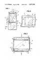
- FIG. 1is an elevational schematic view showing one embodiment of the present invention
- FIG. 3is a schematic view depicting the operation of the gravity flow heat pipe heat exchanger of the present invention.
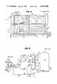
- FIG. 4is an elevational view showing a layout of a system incorporating the present invention and using waste heat to produce domestic hot water;
- Liquid refrigerant 50 disposed in evaporator 28absorbs heat from air flowing over the evaporator and vaporizes.
- the vaporized refrigerant 52rises within evaporator 28 and exits into tube 34.
- the vaporized refrigerantrises through tube 34 and enters condenser 30 through the vapor inlet.
- the air passing over evaporator 28is cooled in this manner and then enters coil 24 which, in this case, acts as an air-conditioner evaporator. Accordingly, coil 24 removes additional heat from the air, which then passes over condenser 30.
- the heat exchangerprovides about 50% free cooling of the incoming air, the air flow can be increased by approximately 50% to keep the evaporation temperature at a normal 40° to 45°.
- the machine 10can have a dehumifidying capacity twice that of a standard air-conditioner of the same tonage, and the ratio of latent heat over total heat removal is approximately 60% to 70%, compared to a typical 30% for a normal air-conditioner.
- both the evaporator 28 and condenser 30can be made with a plurality of coils 60, 62, respectively in order to enhance the evaporation and condensation functions.
- the coils 60can be connected in parallel to one another, as can be coils 62.
- Common headerscan be connected at opposite ends of the coils.
- the inlets and outlets to the evaporator 32 and condenser 30would be connected to the headers at one end at the back of each coil.
- liquid portshould be disposed below the level of the vapor port, that is, liquid inlet 42 must be disposed below the level of vapor outlet 32 and liquid outlet 38 must be disposed below the level of vapor inlet 36 to ensure proper, efficient operation.
- the heat pipe heat exchanger 26can be formed of conventional air-conditioner evaporators, with one conventional air-conditioner evaporator being used as evaporator 28 and a second conventional air-conditioner evaporator being used as condenser 30.
- Standard air-conditioning tubingcan be used as tubing 34 and 40.
- FIGS. 4 and 5show an air-conditioning/dehumidifing system according to the present invention, connected so that waste heat from the system is used to increase the temperature of domestic hot water in a domestic hot water tank 70.
- the air inlet 72 to the systemreceives air at approximately 80°.
- This airis channeled through the evaporators 74, 76, and 78 of three heat pipe heat exchanger units 80, 82, and 84, respectively.
- the incoming airis cooled to approximately 65° by evaporators 74, 76, and 78.
- the airis drawn through the system by a blower 86, which forces the air through an evaporator 88 of the air-conditioning unit and out through condensers 90, 92, and 94 of the heat exchangers 80, 82, and 84, respectively.
- the airis cooled to approximately 50° by evaporator 88 and is then raised to a final temperature of approximately 70° by passing through condensers 90, 92, and 94. It will be noted that the air passing out of the system passes through heat exchanger 84, then heat exchanger 82, and then heat exchanger 80 in the opposite order to the incoming air, which passes through heat exchanger 80 first.
Landscapes
- Engineering & Computer Science (AREA)
- Mechanical Engineering (AREA)
- General Engineering & Computer Science (AREA)
- Physics & Mathematics (AREA)
- Thermal Sciences (AREA)
- Chemical & Material Sciences (AREA)
- Combustion & Propulsion (AREA)
- Life Sciences & Earth Sciences (AREA)
- Sustainable Development (AREA)
- Air Filters, Heat-Exchange Apparatuses, And Housings Of Air-Conditioning Units (AREA)
Abstract
Description
Claims (5)
Priority Applications (1)
| Application Number | Priority Date | Filing Date | Title |
|---|---|---|---|
| US06/614,025US4607498A (en) | 1984-05-25 | 1984-05-25 | High efficiency air-conditioner/dehumidifier |
Applications Claiming Priority (1)
| Application Number | Priority Date | Filing Date | Title |
|---|---|---|---|
| US06/614,025US4607498A (en) | 1984-05-25 | 1984-05-25 | High efficiency air-conditioner/dehumidifier |
Publications (1)
| Publication Number | Publication Date |
|---|---|
| US4607498Atrue US4607498A (en) | 1986-08-26 |
Family
ID=24459589
Family Applications (1)
| Application Number | Title | Priority Date | Filing Date |
|---|---|---|---|
| US06/614,025Expired - LifetimeUS4607498A (en) | 1984-05-25 | 1984-05-25 | High efficiency air-conditioner/dehumidifier |
Country Status (1)
| Country | Link |
|---|---|
| US (1) | US4607498A (en) |
Cited By (50)
| Publication number | Priority date | Publication date | Assignee | Title |
|---|---|---|---|---|
| US5031411A (en)* | 1990-04-26 | 1991-07-16 | Dec International, Inc. | Efficient dehumidification system |
| WO1992019922A1 (en)* | 1991-05-09 | 1992-11-12 | Heat Pipe Technology, Inc. | Booster heat pipe for air conditioning systems |
| WO1994000725A1 (en)* | 1992-06-30 | 1994-01-06 | Khanh Dinh | Serpentine heat pipe and dehumidification application in air conditioning systems |
| US5400607A (en)* | 1993-07-06 | 1995-03-28 | Cayce; James L. | System and method for high-efficiency air cooling and dehumidification |
| US5426953A (en)* | 1993-02-05 | 1995-06-27 | Meckler; Milton | Co-sorption air dehumidifying and pollutant removal system |
| DE19500527A1 (en)* | 1995-01-11 | 1996-07-18 | Kulmbacher Klimageraete | Air conditioner for room |
| WO1996041111A1 (en) | 1995-06-07 | 1996-12-19 | Heat Pipe Technology, Inc. | Serpentine heat pipe and dehumidification application in air conditioning systems |
| EP0775875A3 (en)* | 1995-11-24 | 1997-11-05 | Hans Gössi | Air humidifying and water heating device |
| US5695004A (en)* | 1992-07-10 | 1997-12-09 | Beckwith; William R. | Air conditioning waste heat/reheat method and apparatus |
| US5749415A (en)* | 1997-02-19 | 1998-05-12 | Heat Pipe Technology, Inc. | Roof curb assembly with integral dehumidifier heat pipe controlled by a bypass system |
| US5887651A (en)* | 1995-07-21 | 1999-03-30 | Honeywell Inc. | Reheat system for reducing excessive humidity in a controlled space |
| EP0908687A1 (en)* | 1997-10-09 | 1999-04-14 | J.E. Stork Ventilatoren B.V. | Device for heating water |
| US6109044A (en)* | 1998-01-26 | 2000-08-29 | International Environmental Corp. | Conditioned air fan coil unit |
| US6131653A (en)* | 1996-03-08 | 2000-10-17 | Larsson; Donald E. | Method and apparatus for dehumidifying and conditioning air |
| US6170271B1 (en) | 1998-07-17 | 2001-01-09 | American Standard Inc. | Sizing and control of fresh air dehumidification unit |
| US6209223B1 (en) | 1998-12-08 | 2001-04-03 | Advanced Dryer Systems, Inc. | Grain drying system with high efficiency dehumidifier and modular drying bin |
| US6220337B1 (en)* | 1998-04-27 | 2001-04-24 | Shi-Li Chen | Heat pipe circuit type thermal battery |
| US6279336B1 (en)* | 1997-04-04 | 2001-08-28 | Grundl Und Hoffmann Gmbh Gesellschaft Fur Elektrotechnische | Assembly for switching electrical power |
| US20020038698A1 (en)* | 2000-09-30 | 2002-04-04 | Kwon Yong Kyu | Heat exchanger |
| US6388882B1 (en) | 2001-07-19 | 2002-05-14 | Thermal Corp. | Integrated thermal architecture for thermal management of high power electronics |
| US6591902B1 (en)* | 1998-12-29 | 2003-07-15 | Richard W. Trent | Apparatus for applying controllable, multipurpose heat pipes to heating, ventilation, and air conditioning systems |
| US6644059B2 (en)* | 2001-05-16 | 2003-11-11 | Ebara Corporation | Dehumidifying apparatus |
| DE10238764A1 (en)* | 2002-08-23 | 2004-03-04 | Voith Paper Patent Gmbh | Applicator mechanism is for applying liquid or paste medium on one side or both sides of running paper or board and cools ambient air on applicator surface using heat pipe principle |
| US20050023362A1 (en)* | 2003-08-01 | 2005-02-03 | Honeywell International Inc. | Method and apparatus for controlling humidity with a heater unit and a cooler unit |
| WO2006053081A1 (en)* | 2004-11-10 | 2006-05-18 | Omnova Solutions Inc. | Air conditioner with heat storage |
| US7194870B1 (en)* | 2005-11-16 | 2007-03-27 | Bou-Matic Technologies Llc | High performance dehumidifier |
| US20070120841A1 (en)* | 2002-12-10 | 2007-05-31 | Lg Electronics Inc. | Video overlay device of mobile telecommunication terminal |
| US7246503B1 (en)* | 2005-11-16 | 2007-07-24 | Bou-Matic Technologies Llc | Enhanced drying dehumidifier |
| US7281389B1 (en)* | 2005-11-16 | 2007-10-16 | Bou-Matic Technologies Llc | Enhanced performance dehumidifier |
| US20080223050A1 (en)* | 2007-03-13 | 2008-09-18 | Dri-Eaz Products, Inc. | Dehumidification systems and methods for extracting moisture from water damaged structures |
| US20090126905A1 (en)* | 2007-11-16 | 2009-05-21 | Khanh Dinh | High reliability cooling system for LED lamps using dual mode heat transfer loops |
| US20090126387A1 (en)* | 2007-11-16 | 2009-05-21 | Dinh Research Llc | Duct mounted dehumidifier using parallel air flow |
| US20100125367A1 (en)* | 2008-11-17 | 2010-05-20 | Dri-Eaz Products, Inc. | Methods and systems for determining dehumidifier performance |
| US20100212334A1 (en)* | 2005-11-16 | 2010-08-26 | Technologies Holdings Corp. | Enhanced Performance Dehumidification Apparatus, System and Method |
| US20100269526A1 (en)* | 2009-04-27 | 2010-10-28 | Robert Pendergrass | Systems and methods for operating and monitoring dehumidifiers |
| US20100275630A1 (en)* | 2005-11-16 | 2010-11-04 | Technologies Holdings Corp. | Defrost Bypass Dehumidifier |
| US20100326103A1 (en)* | 2009-06-24 | 2010-12-30 | Karcher North America, Inc. | Dehumidifier for Use in Water Damage Restoration |
| USD634414S1 (en) | 2010-04-27 | 2011-03-15 | Dri-Eaz Products, Inc. | Dehumidifier housing |
| US20110167670A1 (en)* | 2010-01-08 | 2011-07-14 | Karcher North America, Inc. | Integrated Water Damage Restoration System, Sensors Therefor, and Method of Using Same |
| US20130177393A1 (en)* | 2011-05-31 | 2013-07-11 | Carrier Corporation | Hybrid Compressor System and Methods |
| US8534346B1 (en)* | 2006-11-16 | 2013-09-17 | Climatecraft Technologies, Inc. | Flexible heat exchanger |
| US8784529B2 (en) | 2011-10-14 | 2014-07-22 | Dri-Eaz Products, Inc. | Dehumidifiers having improved heat exchange blocks and associated methods of use and manufacture |
| US8893513B2 (en) | 2012-05-07 | 2014-11-25 | Phononic Device, Inc. | Thermoelectric heat exchanger component including protective heat spreading lid and optimal thermal interface resistance |
| US8991194B2 (en) | 2012-05-07 | 2015-03-31 | Phononic Devices, Inc. | Parallel thermoelectric heat exchange systems |
| USD731632S1 (en) | 2012-12-04 | 2015-06-09 | Dri-Eaz Products, Inc. | Compact dehumidifier |
| US20150159920A1 (en)* | 2013-12-10 | 2015-06-11 | Lg Electronics Inc. | Dehumidifier |
| KR101578532B1 (en) | 2015-06-23 | 2015-12-17 | 온시스텍 주식회사 | Energy-saving dehumidification air handling unit |
| US9593871B2 (en) | 2014-07-21 | 2017-03-14 | Phononic Devices, Inc. | Systems and methods for operating a thermoelectric module to increase efficiency |
| US10458683B2 (en) | 2014-07-21 | 2019-10-29 | Phononic, Inc. | Systems and methods for mitigating heat rejection limitations of a thermoelectric module |
| US10989422B1 (en) | 2019-06-28 | 2021-04-27 | William R. Chase, Jr. | Efficient air processing system with heat pipe |
Citations (2)
| Publication number | Priority date | Publication date | Assignee | Title |
|---|---|---|---|---|
| US2093725A (en)* | 1934-12-24 | 1937-09-21 | Gen Motors Corp | Refrigerating apparatus |
| US2905851A (en)* | 1957-10-09 | 1959-09-22 | Westinghouse Electric Corp | Single anode rectifier with forced draft air cooling |
- 1984
- 1984-05-25USUS06/614,025patent/US4607498A/ennot_activeExpired - Lifetime
Patent Citations (2)
| Publication number | Priority date | Publication date | Assignee | Title |
|---|---|---|---|---|
| US2093725A (en)* | 1934-12-24 | 1937-09-21 | Gen Motors Corp | Refrigerating apparatus |
| US2905851A (en)* | 1957-10-09 | 1959-09-22 | Westinghouse Electric Corp | Single anode rectifier with forced draft air cooling |
Non-Patent Citations (13)
| Title |
|---|
| "Fsec Activities" (The Solar Collector", Oct. 1982). |
| "Gainesville Researcher Enhances Air Conditioning" (Aug. 10, 1983). |
| "New Air-Conditioner Unit Can Dry Air, Save Money" (St. Petersburg Times, Aug. 1983). |
| "Q-Pipe Modular Thermal Recovery Unit". |
| "Unique A.C. Unit Cools It, Dries It Up" (The Solar Collector, Jul. 1983). |
| Engineering Thermodynamics, Stoever, 1951, John Wiley & Sons.* |
| Fsec Activities (The Solar Collector , Oct. 1982).* |
| Gainesville Researcher Enhances Air Conditioning (Aug. 10, 1983).* |
| Handbook of Air Conditioning, Strock, 1959 TH 7687 S76 G3, pp. 1 113 & 114.* |
| Handbook of Air Conditioning, Strock, 1959 TH 7687 S76 G3, pp. 1-113 & 114. |
| New Air Conditioner Unit Can Dry Air, Save Money (St. Petersburg Times, Aug. 1983).* |
| Q Pipe Modular Thermal Recovery Unit .* |
| Unique A.C. Unit Cools It, Dries It Up (The Solar Collector, Jul. 1983).* |
Cited By (72)
| Publication number | Priority date | Publication date | Assignee | Title |
|---|---|---|---|---|
| US5031411A (en)* | 1990-04-26 | 1991-07-16 | Dec International, Inc. | Efficient dehumidification system |
| WO1992019922A1 (en)* | 1991-05-09 | 1992-11-12 | Heat Pipe Technology, Inc. | Booster heat pipe for air conditioning systems |
| US5333470A (en)* | 1991-05-09 | 1994-08-02 | Heat Pipe Technology, Inc. | Booster heat pipe for air-conditioning systems |
| US5448897A (en)* | 1991-05-09 | 1995-09-12 | Heat Pipe Technology, Inc. | Booster heat pipe for air-conditioning systems |
| WO1994000725A1 (en)* | 1992-06-30 | 1994-01-06 | Khanh Dinh | Serpentine heat pipe and dehumidification application in air conditioning systems |
| JP3049445B2 (en) | 1992-06-30 | 2000-06-05 | ディン、カーン | Split type meandering heat pipe type heat exchange device, its manufacturing method and its use |
| US5845702A (en)* | 1992-06-30 | 1998-12-08 | Heat Pipe Technology, Inc. | Serpentine heat pipe and dehumidification application in air conditioning systems |
| US5695004A (en)* | 1992-07-10 | 1997-12-09 | Beckwith; William R. | Air conditioning waste heat/reheat method and apparatus |
| US5426953A (en)* | 1993-02-05 | 1995-06-27 | Meckler; Milton | Co-sorption air dehumidifying and pollutant removal system |
| US5400607A (en)* | 1993-07-06 | 1995-03-28 | Cayce; James L. | System and method for high-efficiency air cooling and dehumidification |
| DE19500527A1 (en)* | 1995-01-11 | 1996-07-18 | Kulmbacher Klimageraete | Air conditioner for room |
| WO1996041111A1 (en) | 1995-06-07 | 1996-12-19 | Heat Pipe Technology, Inc. | Serpentine heat pipe and dehumidification application in air conditioning systems |
| US5921315A (en)* | 1995-06-07 | 1999-07-13 | Heat Pipe Technology, Inc. | Three-dimensional heat pipe |
| US5887651A (en)* | 1995-07-21 | 1999-03-30 | Honeywell Inc. | Reheat system for reducing excessive humidity in a controlled space |
| EP0775875A3 (en)* | 1995-11-24 | 1997-11-05 | Hans Gössi | Air humidifying and water heating device |
| US6131653A (en)* | 1996-03-08 | 2000-10-17 | Larsson; Donald E. | Method and apparatus for dehumidifying and conditioning air |
| US5749415A (en)* | 1997-02-19 | 1998-05-12 | Heat Pipe Technology, Inc. | Roof curb assembly with integral dehumidifier heat pipe controlled by a bypass system |
| US6279336B1 (en)* | 1997-04-04 | 2001-08-28 | Grundl Und Hoffmann Gmbh Gesellschaft Fur Elektrotechnische | Assembly for switching electrical power |
| NL1007244C2 (en)* | 1997-10-09 | 1999-04-15 | Stork J E Ventilatoren Bv | Device for heating water. |
| EP0908687A1 (en)* | 1997-10-09 | 1999-04-14 | J.E. Stork Ventilatoren B.V. | Device for heating water |
| US6109044A (en)* | 1998-01-26 | 2000-08-29 | International Environmental Corp. | Conditioned air fan coil unit |
| US6220337B1 (en)* | 1998-04-27 | 2001-04-24 | Shi-Li Chen | Heat pipe circuit type thermal battery |
| US6170271B1 (en) | 1998-07-17 | 2001-01-09 | American Standard Inc. | Sizing and control of fresh air dehumidification unit |
| US6209223B1 (en) | 1998-12-08 | 2001-04-03 | Advanced Dryer Systems, Inc. | Grain drying system with high efficiency dehumidifier and modular drying bin |
| US6591902B1 (en)* | 1998-12-29 | 2003-07-15 | Richard W. Trent | Apparatus for applying controllable, multipurpose heat pipes to heating, ventilation, and air conditioning systems |
| US20020038698A1 (en)* | 2000-09-30 | 2002-04-04 | Kwon Yong Kyu | Heat exchanger |
| US6644059B2 (en)* | 2001-05-16 | 2003-11-11 | Ebara Corporation | Dehumidifying apparatus |
| US6388882B1 (en) | 2001-07-19 | 2002-05-14 | Thermal Corp. | Integrated thermal architecture for thermal management of high power electronics |
| DE10238764A1 (en)* | 2002-08-23 | 2004-03-04 | Voith Paper Patent Gmbh | Applicator mechanism is for applying liquid or paste medium on one side or both sides of running paper or board and cools ambient air on applicator surface using heat pipe principle |
| US20070120841A1 (en)* | 2002-12-10 | 2007-05-31 | Lg Electronics Inc. | Video overlay device of mobile telecommunication terminal |
| US20050023362A1 (en)* | 2003-08-01 | 2005-02-03 | Honeywell International Inc. | Method and apparatus for controlling humidity with a heater unit and a cooler unit |
| WO2006053081A1 (en)* | 2004-11-10 | 2006-05-18 | Omnova Solutions Inc. | Air conditioner with heat storage |
| US7246503B1 (en)* | 2005-11-16 | 2007-07-24 | Bou-Matic Technologies Llc | Enhanced drying dehumidifier |
| US7194870B1 (en)* | 2005-11-16 | 2007-03-27 | Bou-Matic Technologies Llc | High performance dehumidifier |
| US7281389B1 (en)* | 2005-11-16 | 2007-10-16 | Bou-Matic Technologies Llc | Enhanced performance dehumidifier |
| US20080028776A1 (en)* | 2005-11-16 | 2008-02-07 | Bou-Matic Technologies Llc, A Nevada Corporation | Enhanced Performance Dehumidifier |
| US20100275630A1 (en)* | 2005-11-16 | 2010-11-04 | Technologies Holdings Corp. | Defrost Bypass Dehumidifier |
| US8769969B2 (en) | 2005-11-16 | 2014-07-08 | Technologies Holdings Corp. | Defrost bypass dehumidifier |
| US7540166B2 (en) | 2005-11-16 | 2009-06-02 | Technologies Holdings Corp. | Enhanced performance dehumidifier |
| US8347640B2 (en) | 2005-11-16 | 2013-01-08 | Technologies Holdings Corp. | Enhanced performance dehumidification apparatus, system and method |
| US20100212334A1 (en)* | 2005-11-16 | 2010-08-26 | Technologies Holdings Corp. | Enhanced Performance Dehumidification Apparatus, System and Method |
| US8316660B2 (en) | 2005-11-16 | 2012-11-27 | Technologies Holdings Corp. | Defrost bypass dehumidifier |
| US8534346B1 (en)* | 2006-11-16 | 2013-09-17 | Climatecraft Technologies, Inc. | Flexible heat exchanger |
| US20080223050A1 (en)* | 2007-03-13 | 2008-09-18 | Dri-Eaz Products, Inc. | Dehumidification systems and methods for extracting moisture from water damaged structures |
| US8122729B2 (en) | 2007-03-13 | 2012-02-28 | Dri-Eaz Products, Inc. | Dehumidification systems and methods for extracting moisture from water damaged structures |
| US20090126387A1 (en)* | 2007-11-16 | 2009-05-21 | Dinh Research Llc | Duct mounted dehumidifier using parallel air flow |
| US8262263B2 (en) | 2007-11-16 | 2012-09-11 | Khanh Dinh | High reliability cooling system for LED lamps using dual mode heat transfer loops |
| US20090126905A1 (en)* | 2007-11-16 | 2009-05-21 | Khanh Dinh | High reliability cooling system for LED lamps using dual mode heat transfer loops |
| US8290742B2 (en) | 2008-11-17 | 2012-10-16 | Dri-Eaz Products, Inc. | Methods and systems for determining dehumidifier performance |
| US20100125367A1 (en)* | 2008-11-17 | 2010-05-20 | Dri-Eaz Products, Inc. | Methods and systems for determining dehumidifier performance |
| US8572994B2 (en) | 2009-04-27 | 2013-11-05 | Dri-Eaz Products, Inc. | Systems and methods for operating and monitoring dehumidifiers |
| US20100269526A1 (en)* | 2009-04-27 | 2010-10-28 | Robert Pendergrass | Systems and methods for operating and monitoring dehumidifiers |
| US9089814B2 (en) | 2009-04-27 | 2015-07-28 | Dri-Eaz Products, Inc. | Systems and methods for operating and monitoring dehumidifiers |
| US20100326103A1 (en)* | 2009-06-24 | 2010-12-30 | Karcher North America, Inc. | Dehumidifier for Use in Water Damage Restoration |
| US8640360B2 (en) | 2010-01-08 | 2014-02-04 | Karcher North America, Inc. | Integrated water damage restoration system, sensors therefor, and method of using same |
| US20110167670A1 (en)* | 2010-01-08 | 2011-07-14 | Karcher North America, Inc. | Integrated Water Damage Restoration System, Sensors Therefor, and Method of Using Same |
| USD634414S1 (en) | 2010-04-27 | 2011-03-15 | Dri-Eaz Products, Inc. | Dehumidifier housing |
| US20130177393A1 (en)* | 2011-05-31 | 2013-07-11 | Carrier Corporation | Hybrid Compressor System and Methods |
| US8784529B2 (en) | 2011-10-14 | 2014-07-22 | Dri-Eaz Products, Inc. | Dehumidifiers having improved heat exchange blocks and associated methods of use and manufacture |
| US8893513B2 (en) | 2012-05-07 | 2014-11-25 | Phononic Device, Inc. | Thermoelectric heat exchanger component including protective heat spreading lid and optimal thermal interface resistance |
| US8991194B2 (en) | 2012-05-07 | 2015-03-31 | Phononic Devices, Inc. | Parallel thermoelectric heat exchange systems |
| US9103572B2 (en) | 2012-05-07 | 2015-08-11 | Phononic Devices, Inc. | Physically separated hot side and cold side heat sinks in a thermoelectric refrigeration system |
| US9234682B2 (en) | 2012-05-07 | 2016-01-12 | Phononic Devices, Inc. | Two-phase heat exchanger mounting |
| US9310111B2 (en) | 2012-05-07 | 2016-04-12 | Phononic Devices, Inc. | Systems and methods to mitigate heat leak back in a thermoelectric refrigeration system |
| US9341394B2 (en) | 2012-05-07 | 2016-05-17 | Phononic Devices, Inc. | Thermoelectric heat exchange system comprising cascaded cold side heat sinks |
| US10012417B2 (en) | 2012-05-07 | 2018-07-03 | Phononic, Inc. | Thermoelectric refrigeration system control scheme for high efficiency performance |
| USD731632S1 (en) | 2012-12-04 | 2015-06-09 | Dri-Eaz Products, Inc. | Compact dehumidifier |
| US20150159920A1 (en)* | 2013-12-10 | 2015-06-11 | Lg Electronics Inc. | Dehumidifier |
| US9593871B2 (en) | 2014-07-21 | 2017-03-14 | Phononic Devices, Inc. | Systems and methods for operating a thermoelectric module to increase efficiency |
| US10458683B2 (en) | 2014-07-21 | 2019-10-29 | Phononic, Inc. | Systems and methods for mitigating heat rejection limitations of a thermoelectric module |
| KR101578532B1 (en) | 2015-06-23 | 2015-12-17 | 온시스텍 주식회사 | Energy-saving dehumidification air handling unit |
| US10989422B1 (en) | 2019-06-28 | 2021-04-27 | William R. Chase, Jr. | Efficient air processing system with heat pipe |
Similar Documents
| Publication | Publication Date | Title |
|---|---|---|
| US4607498A (en) | High efficiency air-conditioner/dehumidifier | |
| US6018954A (en) | Heat pump system and method for air-conditioning | |
| US6615602B2 (en) | Heat pump with supplemental heat source | |
| US5239838A (en) | Heating and cooling system having auxiliary heating loop | |
| US4567733A (en) | Economizing air conditioning system of increased efficiency of heat transfer selectively from liquid coolant or refrigerant to air | |
| US4796437A (en) | Multifluid heat pump system | |
| US4070870A (en) | Heat pump assisted solar powered absorption system | |
| US4380156A (en) | Multiple source heat pump | |
| US4308042A (en) | Heat pump with freeze-up prevention | |
| CN100557337C (en) | HVAC system with powered subcooler | |
| US7591145B1 (en) | Heat pump/direct expansion heat pump heating, cooling, and dehumidification system | |
| EP0702773B1 (en) | Generator-absorber-heat exchange heat transfer apparatus and method and use thereof in a heat pump | |
| US4856578A (en) | Multi-function self-contained heat pump system | |
| US3938352A (en) | Water to air heat pump employing an energy and condensate conservation system | |
| US5438846A (en) | Heat-pump with sub-cooling heat exchanger | |
| WO2011108068A1 (en) | Air-conditioning hot-water-supplying system | |
| US4667479A (en) | Air and water conditioner for indoor swimming pool | |
| US4413478A (en) | Air conditioning system and method | |
| US20170122624A1 (en) | Multi-stage system for cooling a refrigerant | |
| KR100867619B1 (en) | Air conditioning and hot water supply system using heat pump | |
| EP0824659B1 (en) | Heat pump system and method for air-conditioning | |
| US6631624B1 (en) | Phase-change heat transfer coupling for aqua-ammonia absorption systems | |
| EP0725919B1 (en) | Generator-absorber-heat exchange heat transfer apparatus and method and use thereof in a heat pump | |
| KR20040001006A (en) | Heat pump system having water tank | |
| KR100946381B1 (en) | Hybrid heat pump type cooling and heating apparatus |
Legal Events
| Date | Code | Title | Description |
|---|---|---|---|
| AS | Assignment | Owner name:DINH COMPANY, INC., P.O. BOX 999, 803 N.E. FIRST S Free format text:ASSIGNMENT OF ASSIGNORS INTEREST.;ASSIGNOR:DINH, KHANH;REEL/FRAME:004302/0736 Effective date:19840821 | |
| STCF | Information on status: patent grant | Free format text:PATENTED CASE | |
| FEPP | Fee payment procedure | Free format text:PAYOR NUMBER ASSIGNED (ORIGINAL EVENT CODE: ASPN); ENTITY STATUS OF PATENT OWNER: SMALL ENTITY | |
| FPAY | Fee payment | Year of fee payment:4 | |
| FPAY | Fee payment | Year of fee payment:8 | |
| FPAY | Fee payment | Year of fee payment:12 | |
| AS | Assignment | Owner name:KEETER, ADEN, FLORIDA Free format text:SECURITY AGREEMENT;ASSIGNOR:HEAT PIPE TECHNOLOGY, INC.;REEL/FRAME:009719/0765 Effective date:19980529 | |
| AS | Assignment | Owner name:HEAT-PIPE TECHNOLOGY, INC., FLORIDA Free format text:CHANGE OF NAME;ASSIGNOR:DINH COMPANY, INC.;REEL/FRAME:023538/0813 Effective date:19910620 | |
| AS | Assignment | Owner name:HEAT-PIPE TECHNOLOGY, INC., FLORIDA Free format text:RELEASE BY SECURED PARTY;ASSIGNOR:KEETER, ADEN;REEL/FRAME:023574/0851 Effective date:20021011 | |
| AS | Assignment | Owner name:HEAT PIPE TECHNOLOGY, INC.,FLORIDA Free format text:ASSIGNMENT OF ASSIGNORS INTEREST;ASSIGNOR:DINH, KHANH;REEL/FRAME:023937/0937 Effective date:20091124 |