US4606479A - Pump for dispensing liquid from a container - Google Patents
Pump for dispensing liquid from a containerDownload PDFInfo
- Publication number
- US4606479A US4606479AUS06/600,428US60042884AUS4606479AUS 4606479 AUS4606479 AUS 4606479AUS 60042884 AUS60042884 AUS 60042884AUS 4606479 AUS4606479 AUS 4606479A
- Authority
- US
- United States
- Prior art keywords
- piston
- inlet
- sleeve
- liquid
- valve member
- Prior art date
- Legal status (The legal status is an assumption and is not a legal conclusion. Google has not performed a legal analysis and makes no representation as to the accuracy of the status listed.)
- Expired - Lifetime
Links
- 239000007788liquidSubstances0.000titleclaimsabstractdescription89
- 238000007789sealingMethods0.000claimsabstractdescription33
- 238000013022ventingMethods0.000claimsabstractdescription7
- 239000000463materialSubstances0.000claimsdescription3
- 239000011324beadSubstances0.000description6
- 230000005484gravityEffects0.000description5
- 230000000994depressogenic effectEffects0.000description4
- 239000002304perfumeSubstances0.000description2
- 239000004698PolyethyleneSubstances0.000description1
- 239000000443aerosolSubstances0.000description1
- 238000004891communicationMethods0.000description1
- 238000011109contaminationMethods0.000description1
- 230000007423decreaseEffects0.000description1
- 230000003247decreasing effectEffects0.000description1
- 230000008020evaporationEffects0.000description1
- 238000001704evaporationMethods0.000description1
- 239000012530fluidSubstances0.000description1
- 239000003205fragranceSubstances0.000description1
- 238000012986modificationMethods0.000description1
- 230000004048modificationEffects0.000description1
- 230000003647oxidationEffects0.000description1
- 238000007254oxidation reactionMethods0.000description1
- 229920003023plasticPolymers0.000description1
- 239000004033plasticSubstances0.000description1
- -1polyethylenePolymers0.000description1
- 229920000573polyethylenePolymers0.000description1
- 239000012858resilient materialSubstances0.000description1
- 239000007921spraySubstances0.000description1
Images


Classifications
- B—PERFORMING OPERATIONS; TRANSPORTING
- B05—SPRAYING OR ATOMISING IN GENERAL; APPLYING FLUENT MATERIALS TO SURFACES, IN GENERAL
- B05B—SPRAYING APPARATUS; ATOMISING APPARATUS; NOZZLES
- B05B11/00—Single-unit hand-held apparatus in which flow of contents is produced by the muscular force of the operator at the moment of use
- B05B11/01—Single-unit hand-held apparatus in which flow of contents is produced by the muscular force of the operator at the moment of use characterised by the means producing the flow
- B05B11/10—Pump arrangements for transferring the contents from the container to a pump chamber by a sucking effect and forcing the contents out through the dispensing nozzle
- B05B11/1001—Piston pumps
- B05B11/1016—Piston pumps the outlet valve having a valve seat located downstream a movable valve element controlled by a pressure actuated controlling element
- B05B11/1018—Piston pumps the outlet valve having a valve seat located downstream a movable valve element controlled by a pressure actuated controlling element and the controlling element cooperating with means for opening or closing the inlet valve
- B—PERFORMING OPERATIONS; TRANSPORTING
- B05—SPRAYING OR ATOMISING IN GENERAL; APPLYING FLUENT MATERIALS TO SURFACES, IN GENERAL
- B05B—SPRAYING APPARATUS; ATOMISING APPARATUS; NOZZLES
- B05B11/00—Single-unit hand-held apparatus in which flow of contents is produced by the muscular force of the operator at the moment of use
- B05B11/01—Single-unit hand-held apparatus in which flow of contents is produced by the muscular force of the operator at the moment of use characterised by the means producing the flow
- B05B11/10—Pump arrangements for transferring the contents from the container to a pump chamber by a sucking effect and forcing the contents out through the dispensing nozzle
- B05B11/1042—Components or details
- B05B11/1043—Sealing or attachment arrangements between pump and container
- B05B11/1046—Sealing or attachment arrangements between pump and container the pump chamber being arranged substantially coaxially to the neck of the container
- B—PERFORMING OPERATIONS; TRANSPORTING
- B05—SPRAYING OR ATOMISING IN GENERAL; APPLYING FLUENT MATERIALS TO SURFACES, IN GENERAL
- B05B—SPRAYING APPARATUS; ATOMISING APPARATUS; NOZZLES
- B05B11/00—Single-unit hand-held apparatus in which flow of contents is produced by the muscular force of the operator at the moment of use
- B05B11/01—Single-unit hand-held apparatus in which flow of contents is produced by the muscular force of the operator at the moment of use characterised by the means producing the flow
- B05B11/10—Pump arrangements for transferring the contents from the container to a pump chamber by a sucking effect and forcing the contents out through the dispensing nozzle
- B05B11/1042—Components or details
- B05B11/1061—Pump priming means
Definitions
- the present inventionrelates to manually operated pumps for dispensing liquid from a container. More specifically, the present invention relates to a non-throttling dispensing pump of the type having a manually operated actuator.
- a conventional non-throttling pump for dispensing liquid from a containerincludes a cylinder having an inlet for receiving liquid from the container through a dip tube and a piston slidable reciprocally in the cylinder.
- the pistonhas an interior chamber having an opening at one end thereof for dispensing liquid from the chamber.
- a valve memberis positioned in the chamber and has a dispensing valve at one end portion biased toward a position closing the opening of the piston. The valve member is movable under liquid pressure against the bias away from the opening to dispense liquid from the chamber.
- a typical inlet valveis a free floating ball which seats on a circular valve seat.
- the ball valveseats to close the chamber during the initial portion of the stroke of the actuator. Because the valve member is biased toward a position closing the dispensing opening of the piston, a chamber is defined, and the chamber decreases in volume as the actuator is pushed downwardly. As pressure builds up in the chamber, the valve member positioned in the chamber is urged downwardly under liquid pressure against its bias to dispense liquid from the chamber.
- An inlet valve using a ball-type check valveis disadvantageous for several reasons.
- the check valveis held in a closed position by gravity.
- the check valvemay not seat during initial portion of the stroke of the actuator, and thus the volume of the liquid dispensed may be decreased and throughout a series of actuations the volume dispensed may be erratic.
- the ball-type check valvetends to inhibit smooth flow of liquid up into the chamber for the next stroke.
- U.S. Pat. No. 4,025,046 to Borisdiscloses an inlet valve wherein a cylindrical sleeve slides over an elongate tubular projection.
- the cylindrical sleevewhich cooperates with this tubular projection to form a seal, permits inflow of liquid into the dispensing chamber only during a latter portion of the return stroke.
- the pumpmay be operated so that full return of the actuator is not permitted. For example, a person may use the pump by pressing the actuator downwardly for a full stroke, and then permit the actuator to rise under its bias to half of the length of its return stroke, which movement is insufficient to open the valve.
- U.S. Pat. No. 4,212,332 to Kutik et aldiscloses a manually operated pump wherein the floating valve is slidable with respect to the actuator.
- the floating valvehas a generally cylindrical configuration with inwardly bent fingers at its upper region which frictionally engage the outside of the cylindrical actuator but which permit flow of liquid between the fingers.
- Each of the fingersis biased to engage the actuator tightly but yield to permit the actuator to slide with respect to the valve when a tapered valve tip on the lower portion of the floating valve seats on a valve seat.
- the pump disclosed in the Kutik et al patentonce the tapered tip seats on the valve seat, the liquid pressure inside the floating valve is equal to the liquid pressure on the outside of the floating valve because there are ports permitting fluid communication between both the inside and outside of the valve. Because of this pressure equilibrium, the valve disclosed in Kutik et al patent would not function in a conventional non-throttling pump, wherein a pressure differential is necessary to move the valve member.
- a pump in accordance with one aspect of the present inventionincludes an inlet valve for opening and closing the inlet of the pump.
- the pumpincludes a cylinder, a piston having an interior chamber and a valve member positioned in the chamber.
- the valve memberhas a dispensing valve at one end portion biased toward a position closing an opening in the upper end of the piston at the top of the chamber.
- the opposite end of the valve memberincludes an elongate cylindrical surface that coacts with an inlet valve to provide for sealing of the inlet opening during dispensing and opening of the inlet to allow suctioning of liquid into the dispensing chamber during the return stroke of the actuator.
- the inlet valvehas a cylindrical surface that has a diameter sized to frictionally engage, provide a liquid seal, and slide with respect to the cylindrical surface of the valve member.
- the inlet valvemoves with the cylindrical portion of the valve member until it is seated on the inlet. Thereafter, the inlet valve slides with respect to the cylindrical end portion of the valve member during further travel of the valve member with respect to the cylinder.
- the movement of the pistonreduces the volume of the dispensing chamber thereby increasing the pressure in the chamber to provide a positive pressure differential between the chamber and the container which holds the liquid.
- the pressure differentialforces the inlet valve against the inlet to seal the chamber with respect to the container.
- the positive pressure differentialprovides a tight seal that prevents seepage of liquid back into the liquid container during the dispensing stroke. Because the inlet valve does not work under a gravity principle, the pump may be operated at any angle thereby providing a distinct advantage over conventional ball check valves.
- the inlet valvecomprises a generally cylindrical sleeve having a cylindrical surface on its interior.
- the sleevehas an inner diameter sized to frictionally engage the elongate cylindrical surface of the valve member.
- the inletcomprises an opening circumferenced by an annular ring protruding upwardly from the floor.
- the ringhas an outer diameter sized to fit within the sleeve.
- a sealing collarfor use in sealing the pump with respect to the container.
- a conventional containerhas a radially protruding flange to which the pump must be attached.
- a sealing collaris provided and comprises a resilient body having a central aperture for receiving the pump.
- the bodyincludes at its periphery a circular sealing ring having a generally U-shaped cross-section.
- the cross-sectionhas a floor for contacting the container flange, and an inner and outer sidewall having a space therebetween the outer sidewall at the bottom thereof includes a wedge-shaped sealing member which is forced into a space between the container flange and a mounting cup.
- the seal collaris installed onto the container flange with the use of a mounting cup having an upper end portion which engages the pump and a lower end portion that is crimped around the bottom lip of the bottle flange.
- the mounting cupholds the pump in place with respect to the container.
- the two circular areas of contact between the sealing collar and the beadprovide a double seal.
- the downward pressure of the mounting cup on the outer sidewall of the sealforces a wedge-shaped sealing member into the space between the edge of the flange and the mounting cup thereby providing a tight seal.
- the pumpis air tight, that is, the pump is "non-venting". Because the volume of liquid dispensed is not replaced with air, a partial vacuum builds in the container.
- a pump in accordance with one aspect of the inventionwill function with a partial vacuum in the container.
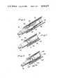
- FIGS. 1, 2, 3, and 4are cross-sectional views of a pump in accordance with the present invention in various states of operation;
- FIG. 1shows the pump in its rest position
- FIG. 2shows the pump in the position wherein liquid is dispensed
- FIG. 3shows the pump wherein the actuator has been fully depressed
- FIG. 4shows the pump in a position wherein liquid is being suctioned from the container
- FIG. 5shows an exploded sectional view of a mounting cup, a sealing collar and the bead of the container which holds the liquid;
- FIG. 6shows a perspective view, partially sectioned away, of the pump shown in FIGS. 1-5 in the position of FIG. 4;
- FIG. 7shows a perspective view, partially sectioned away, of the pump shown in FIGS. 1-5 in the position of FIG. 2;
- FIG. 8is a perspective view, partially sectioned away, of an alternative embodiment of a pump in accordance with the present invention.
- FIG. 1shows a cross-sectional view of the pump in its rest position.
- the pump 10has an actuator 12 attached thereto and is secured to a container 14 by the use of a mounting cup 16.
- a sealing collar 18seals the pump with respect to the container 14 and with respect to the piston stem 10 to prevent or reduce evaporation of liquid from the container and contamination of the liquid stored in the container by leakage of air into the container.
- the actuator 12includes an upper surface 20 for finger actuation as well as a nozzle 22 to disperse liquid in a fine, aerosol spray as shown at reference character 24 of FIG. 2.
- the actuatorhas a cylindrical recess 26 for snugly receiving the upper portion 28 of the pump 10.
- the pump 10includes a cylinder 30 having an inlet 32 for receiving liquid from the container 14.
- the inlethas secured thereto an elongate dip tube 34 which extends to the bottom of the container 14 and functions as a conduit for delivering liquid to the pump.
- a piston 36is slidable within cylinder 30.
- the pistonincludes a lower skirt 38 having a diameter sized to snugly engage the interior wall 40 of cylinder 30.
- the pistonis slidable reciprocally in the cylinder 30 and has an interior chamber 42 along its length.
- the pistonhas an opening 44 at one end thereof for dispensing liquid from the chamber and is slidable through a downward stroke from the position shown in FIG. 1 to the position shown in FIG. 3.
- the pistonwill move under spring bias from the position shown in FIG. 3 to the position shown in FIG. 4.
- a valve member 46is positioned in the chamber 42.
- the valve member 46includes a dispensing valve 48 at one end portion biased toward a position closing the opening 44 of the piston.
- the valve memberincludes a radial protrusion 50 that defines beneath it an annular recess 52 for receiving the uppermost coil 54 of helical spring 56.
- the helical spring 56biases the valve member upwardly toward the position shown in FIG. 1. Because the dispensing valve at the top of the valve member is in contact with the upper portion of the piston, the helical spring also biases the piston to its uppermost position as shown in FIG. 1.
- the valve member 46is movable under liquid pressure against the bias of spring 56 away from the discharge opening 44 to dispense liquid from the chamber of the piston.
- the lower end portion 58 of the valve memberwhich is also termed a "tail" has an elongate cylindrical surface 60.
- An inlet valveis provided for closing and opening the inlet 32.
- the inlet valve 62includes a cylindrical surface 64 which has a diameter 66 sized to frictionally engage, provide a liquid seal, and slide with respect to the cylindrical surface 60 of the tail 58 of the valve member.
- the inlet valve 62comprises a generally cylindrical sleeve having the cylindrical surface 64 on its interior.
- the cylinder 30has a floor 70 adjacent the inlet 32.
- the inlet opening 32is circumferenced by an annular ring 72 projecting upwardly from the floor 70.
- the ring 72has an outer diameter sized to fit within the sleeve, that is, its diameter permits the sleeve 62 to completely surround the ring as shown in FIG. 2.
- the ring 72includes an outer surface 74 tapering inwardly as it extends upwardly from the floor.
- the outer surface 74provides a seat upon which the interior cylindrical surface 64 of the sleeve seats to close the inlet.
- FIGS. 1 and 2as the sleeve contacts the outer surface 74 of the ring 72 it is deformed slightly radially outwardly thereby providing a tight fit between the sleeve and the outer wall 74 of the ring.
- the ring 72is tapered so that when the sleeve is moved upwardly, inflow of liquid through the inlet is permitted as soon as the actuator moves upwardly by release of finger pressure.
- the interior cylindrical surface of cylinder 30includes a stepped portion 80 which retains the end of helical spring 56 between it and the cylindrical sleeve.
- the springforms a protrusion at its bottom coil that limits upward travel of the sleeve.
- the sleevehas an annular stop surface 82 that projects radially outwardly from the outer surface of the sleeve. As the sleeve moves upwardly, this stop surface contacts the end coil of helical spring 56 thereby preventing further upward movement of the sleeve.
- a land surface 90is provided on the interior surface of the cylinder.
- an air spaceis provided which permits air to move past the piston into an empty volume 92 and through a space 94 between the container and the outer wall of cylinder 30 (FIG. 3).
- the path of the airis shown in FIG. 3 at arrows 96a and 96b.
- the space 92is provided by the absence of annular flange 98 in at least one segment of its arc. More specifically, annular flange 98 extends circumferentially around the top of the cylinder except at one or more points where a gap or space 92 is provided.
- the actuator 12is depressed with respect to the container 14 by finger force on upper surface 20. As shown in the comparison between FIGS. 1 and 2, as the actuator 12 is moved downwardly, the piston is also forced downwardly and slides with respect to cylinder 30. The tail end portion 58 of the valve member moves the sleeve 62 to the position shown in FIG. 2. As the actuator 12 is depressed further, the liquid pressure in the dispensing chamber builds up and forces the sleeve radially inwardly against the ring 72.
- the resilient deformable sleeveis pressed tightly against the ring 72 and tail end 58 and seals the chamber 42 with respect to the container 14.
- the cylindrical sleevebe sized to provide a liquid seal between it and the tail of the valve body so that the pressure inside the sleeve is maintained at the pressure of the container and liquid is prevented from flowing back into the container.
- the maintainence of the low pressure inside the cylindrical sleevealso permits the valve member 46 to slide with respect to the sleeve 62 due to the pressure differential between the chamber and inside the sleeve 62.
- the stop surface 82contacts the lowermost coil of helical spring 56 and is prevented from further upward movement. This stop surface maintains the sleeve in close proximity to the ring 72 so that when the actuator is depressed again, immediate sealing takes place.
- the pumpis operated in such a manner that the actuator and the internal components move through a full stroke to the position shown in FIG. 3.
- personsmay actutate the pump by moving the actuator through only a portion of the stroke.
- the sleeveseals the interior chamber with respect to the container thus permitting dispensing upon buildup of pressure.
- the sleevemoves away from the ring, and liquid is permitted to be suctioned into the dispensing chamber.
- the sealing collar 18comprises a resilient body made of polyethylene or other resilient material.
- the collarhas a central aperture 100 for receiving the piston 10 of the pump.
- the collar at its peripheryincludes a circular sealing ring 102 having a generally U-shaped cross-section.
- the ringhas a floor 104, an inner sidewall 106 and an outer sidewall 108.
- the sidewalls 106 and 108have a space 110 therebetween for accomodating the bead 115 on the upper surface 112 of the flange 114 when the pump is assembled.
- the bead 115protrudes upwardly from the upper surface 112 of the flange 114 and extends in a circle around the flange.
- the annular outer sidewall 108includes at the bottom thereof a sealing member 109 that has a wedge-shaped cross-section. This sealing member extends around the entire periphery of the sealing collar.
- the wedge-shaped sealing member 109is driven into a space between the mounting cup 16 and the rounded flange of the bottle to provide a liquid and air-tight seal between the sealing collar and the bottle flange.
- the mounting cup wall 17has an inner diameter 116 which is smaller than the outer diameter 118 of the outer sidewall of the U-shaped ring. Also, as shown in FIGS. 2 and 5, the height of the outer sidewall 108 is sized so that it is compressed axially when the mounting cup 16 is attached to the container flange 114. As shown in the drawings, the mounting cup 16 is crimped onto the bottle flange. However, it should be understood that other manners of securement may be used, such as a threaded mounting cup which is screwed to a threaded bottle flange.
- the sealing collar 18is shown assembed with the other components of the pump.
- the outer sidewall 108is compressed axially so that the wedge-shaped seal 109 is forced downwardly into the space between the rounded segment of the flange 114 and the interior surface of wall 17 of mounting cup 16.
- This wedge-shaped seal 109provides a liquid and airtight seal between the flange 114 of the bottle and the sealing collar.
- bead 115is forced upwardly into floor 104 of the sealing collar and as shown in a comparison between FIGS. 2 and 5, deforms the floor upwardly into space 110. This second deformation provides an additional seal to prevent liquid and air leakage.
- a rim 126extends radially inwardly from the inner sidewall 106 of the U-shaped ring.
- a radially projecting flange 98 of the cylinder 30fits over the rim 126 and holds the rim in contact with the container flange 114.
- the inner sidewall 106is compressed and forced radially downwardly to urge the floor 104 into contact with the upper surface of flange 114. Since both sidewalls 106 and 108 are axially compressed and forced downwardly against the upper surface of flange 114, a seal having two discrete areas of contact is provided and produces an effective liquid and air seal.
- the pumpis non-venting.
- the central aperture 100 of the sealing collar 18includes a sleeve 132 which projects downwardly and radially inwardly so that when the piston is positioned in opening 100, the sleeve is deformed slightly and contacts the piston about its circumference.
- the sleeveremains in contact with the piston throughout pump actuation so that it precludes or minimizes the incursion of air into the container.
- the sleevealso acts as a wiper to eliminate or minimize the escape of liquid from the container.
- the pistonincludes an annular groove 138 into which the sleeve 132 seats when the pump is in a rest position.
- Sleeve 132is preferably integrally formed with ceiling collar 18 and, as shown in FIG. 4, is supported on a vertical post 133 that has an annular shape.
- a radially extending bridge 135secures sleeve 132 to the vertical annular post 133. Since the sealing collar 18 is made of a resilient plastic material and sleeve 132 has a relatively small thickness, the sleeve 132 remains flexible during pump actuation. As shown in FIG. 5, the sleeve 132 has a frustoconical shape before the piston is inserted into opening 100. When the piston is inserted, as shown in FIG. 4, the sleeve 132 is deformed slightly radially outwardly and is in contact with the surface of the piston.
- a ventis provided to permit entry of air into the container to replace the liquid displaced from the container.
- a conventional pumpprovides a vent so that a vacuum will not build up in the container, but is disadvantageous in that liquid may leak through the vent.
- the pumpis non-venting and a build up of a partial vacuum in a container is permissible.
- the advantage of a vacuum in the containeris that the amount of air in contact with the liquid is reduced and leakage of liquid will not occur. Liquids which are readily oxidized or deteriorate in air may be stored over a relatively longer period of time. For example, in the case of perfumes, it is desirable to prevent oxidation of the liquid which may alter the fragrance of the perfume.
- the partial vacuumoccurs as liquid is dispensed.
- a non-venting pump in accordance with the present inventioncan be actuated with a vacuum in the container because the diameter of the stem 28 of the piston 36 is of reduced size thereby minimizing the force of the vacuum on the piston.
- a pump in accordance with the present inventionmay have a relatively small diameter piston stem 28. If a piston stem having a large diameter stem is used with a non-venting pump wherein a vacuum occurs in the container, the forces on the piston may be such that a stronger helical spring is required, thus requiring excessive finger pressure for actuation.
- Valve member 246includes an elongate cylindrical hollow portion 245 which receives cylindrical sleeve 247.
- the outer diameter of sleeve 247is sized to fit tightly within the inner diameter of valve member 246 and annular ring 248 extends upwardly from the floor 249 of the cylinder 250.
- the sleeve 247includes stop surfaces 251 which functions in a manner similar to stop surfaces 82, and limits the upward travel of the cylindrical sleeve.
- a pump in accordance with the present inventionhas a reduced number of components in that a complicated non-throttling mechanism has been eliminated and this function is combined with the inlet check valve. Also, if desired, the entire pump may be constructed of nonrubber materials, which in conventional pumps tend to contaminate the product being dispensed.
- a pump in accordance with the present inventionis particularly advantageous in that it may be operated in various positions, and the check valve does not depend upon gravity for operation.
- the pressure build up in the dispensing chamberforces the inlet valve against its seat thereby making a firm, liquid tight seal during the dispensing stroke.
- the pumpis attached to the flange of a conventional container with the use of a unique sealing collar having a wedge-shaped sealing member which is forced into a space between the mounting cup and the rounded flange of the bottle to provide an effective seal.
Landscapes
- Closures For Containers (AREA)
- Details Of Reciprocating Pumps (AREA)
Abstract
Description
Claims (13)
Priority Applications (8)
| Application Number | Priority Date | Filing Date | Title |
|---|---|---|---|
| US06/600,428US4606479A (en) | 1984-04-16 | 1984-04-16 | Pump for dispensing liquid from a container |
| DE8888117695TDE3584171D1 (en) | 1984-04-16 | 1985-04-11 | SEALING ARRANGEMENT AND SEALING RING FOR A LIQUID DISPENSING DEVICE. |
| DE8585902255TDE3586780T2 (en) | 1984-04-16 | 1985-04-11 | PUMP FOR DISTRIBUTING A LIQUID FROM A CONTAINER. |
| EP85902255AEP0179853B1 (en) | 1984-04-16 | 1985-04-11 | Pump for dispensing liquid from a container |
| EP88117695AEP0309001B1 (en) | 1984-04-16 | 1985-04-11 | A sealing assembly and sealing collar for use in a liquid dispensing device |
| PCT/US1985/000637WO1985004852A1 (en) | 1984-04-16 | 1985-04-11 | Pump for dispensing liquid from a container |
| CA000479081ACA1246504A (en) | 1984-04-16 | 1985-04-15 | Pump for dispensing liquid from a container |
| US07/456,603US5108013A (en) | 1984-04-16 | 1989-12-22 | Pump for dispensing liquid from a container |
Applications Claiming Priority (1)
| Application Number | Priority Date | Filing Date | Title |
|---|---|---|---|
| US06/600,428US4606479A (en) | 1984-04-16 | 1984-04-16 | Pump for dispensing liquid from a container |
Related Child Applications (1)
| Application Number | Title | Priority Date | Filing Date |
|---|---|---|---|
| US06862044Division | 1986-05-12 |
Publications (1)
| Publication Number | Publication Date |
|---|---|
| US4606479Atrue US4606479A (en) | 1986-08-19 |
Family
ID=24403556
Family Applications (1)
| Application Number | Title | Priority Date | Filing Date |
|---|---|---|---|
| US06/600,428Expired - LifetimeUS4606479A (en) | 1984-04-16 | 1984-04-16 | Pump for dispensing liquid from a container |
Country Status (5)
| Country | Link |
|---|---|
| US (1) | US4606479A (en) |
| EP (2) | EP0309001B1 (en) |
| CA (1) | CA1246504A (en) |
| DE (2) | DE3586780T2 (en) |
| WO (1) | WO1985004852A1 (en) |
Cited By (32)
| Publication number | Priority date | Publication date | Assignee | Title |
|---|---|---|---|---|
| US4787558A (en)* | 1985-05-16 | 1988-11-29 | Rain Bird Consumer Products Mfg. Corp. | Rotary drive sprinkler |
| US4821928A (en)* | 1987-09-25 | 1989-04-18 | Su Cheng Y | Moveable valve structure for perfume atomizers |
| US4984702A (en)* | 1990-03-30 | 1991-01-15 | Specialty Packaging Licensing Company, Inc. | Assembly for securing and sealing a dispenser to a flanged container |
| US4986453A (en)* | 1989-05-15 | 1991-01-22 | The Pittway Corporation | Atomizing pump |
| US5002228A (en)* | 1989-07-14 | 1991-03-26 | Su Jeno Y | Atomizer |
| US5020696A (en)* | 1989-11-27 | 1991-06-04 | Rjs Industries, Inc. | Atomizing fluid dispenser two |
| US5038501A (en)* | 1990-06-12 | 1991-08-13 | Black & Decker Inc. | Pump having a rotary two-position selector valve for a steam/spray iron |
| US5046644A (en)* | 1989-11-27 | 1991-09-10 | American Dispensing Systems Inc. | Atomizing fluid dispenser one |
| US5069369A (en)* | 1990-02-27 | 1991-12-03 | Risdon Corporation | Method and assembly for retaining a mounting cup with a sealing collar |
| US5152435A (en)* | 1991-06-13 | 1992-10-06 | Ben Zane Cohen | Ophthalmic dispensing pump |
| US5257726A (en)* | 1985-08-14 | 1993-11-02 | Ing. Erich Pfeiffer Gmbh & Co. Kg | Dispenser for flowable media |
| US5370280A (en)* | 1993-12-14 | 1994-12-06 | Su; Cheng-Yuan | Valve for a sprayer |
| US5503306A (en)* | 1994-10-19 | 1996-04-02 | Aptar Group, Inc. | Manually actuated pump |
| US5505343A (en)* | 1994-10-19 | 1996-04-09 | Knickerbocker; Michael G. | Manually actuated pump |
| US5562234A (en)* | 1995-10-12 | 1996-10-08 | Su; Cheng-Yuan | Hand sprayer |
| US5579958A (en)* | 1995-10-12 | 1996-12-03 | Su; Cheng-Yuan | Liquid sprayer |
| US5687883A (en)* | 1995-11-16 | 1997-11-18 | Su; Cheng-Yuan | Inductor valve of an atomizer |
| US5692648A (en)* | 1995-11-16 | 1997-12-02 | Su; Cheng-Yuan | Sealing cap of an atomizer |
| USD396188S (en) | 1996-02-23 | 1998-07-21 | Owens-Illinois Closure Inc. | Liquid dispenser |
| US5850948A (en)* | 1996-09-13 | 1998-12-22 | Valois S.A. | Finger-operable pump with piston biasing post |
| US5918778A (en)* | 1997-12-19 | 1999-07-06 | Emson, Inc. | Pump and pump securing device which maintains consistent dosage accuracy, and method of securing a pump to a container |
| US5947340A (en)* | 1995-12-06 | 1999-09-07 | The Procter & Gamble Company | Manually-actuated high pressure spray pump |
| USD414696S (en) | 1998-12-03 | 1999-10-05 | Owens-Illinois Closure Inc. | Liquid dispenser |
| USD414697S (en) | 1998-12-03 | 1999-10-05 | Owens-Illinois Closure Inc. | Liquid dispenser |
| USD419877S (en)* | 1998-12-03 | 2000-02-01 | Owens-Illinois Closure Inc. | Liquid dispenser |
| US6032833A (en)* | 1998-07-24 | 2000-03-07 | Olegnowicz; Israel | Non-throttling valve assembly |
| US6126038A (en)* | 1998-10-30 | 2000-10-03 | Olegnowicz; Israel | Atomizing pump spray |
| USD441654S1 (en) | 1997-04-18 | 2001-05-08 | Owens-Illinois Closure Inc. | Liquid dispenser |
| US20040251280A1 (en)* | 2001-06-01 | 2004-12-16 | Daniel Crosnier | Dosage pump |
| US20060131342A1 (en)* | 2003-05-16 | 2006-06-22 | Jean-Louis Bougamont | Distributor for a liquid or gel product |
| US20080067196A1 (en)* | 2005-04-21 | 2008-03-20 | Jean-Luc Octau | Pump For Fluid Product Dispenser Having A Body Comprising An Assembling And Sealing Flange Ring |
| JP2011072884A (en)* | 2009-09-29 | 2011-04-14 | Yoshino Kogyosho Co Ltd | Liquid material discharge pump |
Families Citing this family (7)
| Publication number | Priority date | Publication date | Assignee | Title |
|---|---|---|---|---|
| FR2620052B1 (en)* | 1987-09-09 | 1990-04-27 | Valois | MANUAL PUMP TYPE PREPRESSURE VAPORIZER FOR USE WITH A PROPELLANT GAS |
| IT1219694B (en)* | 1988-05-24 | 1990-05-24 | Sar Spa | SEALING DEVICE FOR HAND PUMPS DISPENSING PRODUCTS IN PASTA OR LIQUIDS |
| US5277559A (en)* | 1992-11-25 | 1994-01-11 | Emson Research, Inc. | Sliding seal pump |
| ES2165789B1 (en)* | 1999-12-27 | 2003-10-01 | Saint Gobain Calmar Sa | PRECOMPRESSION PUMP ATOMIZER. |
| FR2811383B1 (en)* | 2000-07-07 | 2002-12-13 | Valois Sa | FLUID PRODUCT DISPENSING PUMP |
| FR2838786B1 (en)* | 2002-04-17 | 2005-11-04 | Valois Sa | FLUID PRODUCT DELIVERY PUMP |
| FR2996543B1 (en) | 2012-10-05 | 2015-05-29 | Qualipac Sa | METHOD FOR ASSEMBLING A PACKING DEVICE |
Citations (9)
| Publication number | Priority date | Publication date | Assignee | Title |
|---|---|---|---|---|
| US2362080A (en)* | 1942-10-26 | 1944-11-07 | Wilco Company | Dispensing device |
| US4025046A (en)* | 1975-03-28 | 1977-05-24 | Societe Technique De Pulverisation | Liquid atomisers |
| US4122982A (en)* | 1976-03-16 | 1978-10-31 | Coster Tecnologie Speciali S.P.A. | Aerosol metering valve provided with pumping effect |
| US4173297A (en)* | 1978-01-30 | 1979-11-06 | The Risdon Manufacturing Company | Non-throttling manually reciprocated plunger pump for consumer-type liquid dispensing containers |
| US4212332A (en)* | 1978-02-21 | 1980-07-15 | Security Plastics, Inc. | Manually operated pump for dispensing product from a container |
| US4230242A (en)* | 1979-03-26 | 1980-10-28 | Philip Meshberg | Triple seal valve member for an atomizing pump dispenser |
| US4271990A (en)* | 1978-05-12 | 1981-06-09 | Security Plastics, Inc. | Pumping system for dispensing product from a container |
| US4278189A (en)* | 1979-12-17 | 1981-07-14 | Ethyl Products Company | Accumulative pressure pump |
| US4317531A (en)* | 1979-06-28 | 1982-03-02 | Yoshino Kogyosho Co., Ltd. | Accumulator type manual atomizer |
Family Cites Families (6)
| Publication number | Priority date | Publication date | Assignee | Title |
|---|---|---|---|---|
| AT189528B (en)* | 1952-08-13 | 1957-04-10 | Hellmut Golde | Closure cap for bottles and. Like. Container |
| DE1164864B (en)* | 1958-06-20 | 1964-03-05 | Metallwerke Adolf Hopf K G | Bottle cap |
| US3539083A (en)* | 1968-12-17 | 1970-11-10 | Dart Ind Inc | Bag in can aerosol container |
| US4144987A (en)* | 1973-11-07 | 1979-03-20 | Yoshino Kogyosho Co., Ltd. | Liquid sprayer |
| DE2711795A1 (en)* | 1977-03-18 | 1978-09-21 | Lindal Gmbh Aerosol Tech | Dispensing pump head for aerosol containers - has cylindrical sleeve with flange as non return valve for cheap manufacture |
| US4475274A (en)* | 1982-07-07 | 1984-10-09 | Hunt-Wesson Foods, Inc. | Method of making and installing a pouring fitment |
- 1984
- 1984-04-16USUS06/600,428patent/US4606479A/ennot_activeExpired - Lifetime
- 1985
- 1985-04-11WOPCT/US1985/000637patent/WO1985004852A1/enactiveIP Right Grant
- 1985-04-11EPEP88117695Apatent/EP0309001B1/ennot_activeExpired
- 1985-04-11EPEP85902255Apatent/EP0179853B1/ennot_activeExpired
- 1985-04-11DEDE8585902255Tpatent/DE3586780T2/ennot_activeExpired - Fee Related
- 1985-04-11DEDE8888117695Tpatent/DE3584171D1/ennot_activeExpired - Lifetime
- 1985-04-15CACA000479081Apatent/CA1246504A/ennot_activeExpired
Patent Citations (9)
| Publication number | Priority date | Publication date | Assignee | Title |
|---|---|---|---|---|
| US2362080A (en)* | 1942-10-26 | 1944-11-07 | Wilco Company | Dispensing device |
| US4025046A (en)* | 1975-03-28 | 1977-05-24 | Societe Technique De Pulverisation | Liquid atomisers |
| US4122982A (en)* | 1976-03-16 | 1978-10-31 | Coster Tecnologie Speciali S.P.A. | Aerosol metering valve provided with pumping effect |
| US4173297A (en)* | 1978-01-30 | 1979-11-06 | The Risdon Manufacturing Company | Non-throttling manually reciprocated plunger pump for consumer-type liquid dispensing containers |
| US4212332A (en)* | 1978-02-21 | 1980-07-15 | Security Plastics, Inc. | Manually operated pump for dispensing product from a container |
| US4271990A (en)* | 1978-05-12 | 1981-06-09 | Security Plastics, Inc. | Pumping system for dispensing product from a container |
| US4230242A (en)* | 1979-03-26 | 1980-10-28 | Philip Meshberg | Triple seal valve member for an atomizing pump dispenser |
| US4317531A (en)* | 1979-06-28 | 1982-03-02 | Yoshino Kogyosho Co., Ltd. | Accumulator type manual atomizer |
| US4278189A (en)* | 1979-12-17 | 1981-07-14 | Ethyl Products Company | Accumulative pressure pump |
Cited By (35)
| Publication number | Priority date | Publication date | Assignee | Title |
|---|---|---|---|---|
| US4787558A (en)* | 1985-05-16 | 1988-11-29 | Rain Bird Consumer Products Mfg. Corp. | Rotary drive sprinkler |
| US5257726A (en)* | 1985-08-14 | 1993-11-02 | Ing. Erich Pfeiffer Gmbh & Co. Kg | Dispenser for flowable media |
| US4821928A (en)* | 1987-09-25 | 1989-04-18 | Su Cheng Y | Moveable valve structure for perfume atomizers |
| US4986453A (en)* | 1989-05-15 | 1991-01-22 | The Pittway Corporation | Atomizing pump |
| US5002228A (en)* | 1989-07-14 | 1991-03-26 | Su Jeno Y | Atomizer |
| US5046644A (en)* | 1989-11-27 | 1991-09-10 | American Dispensing Systems Inc. | Atomizing fluid dispenser one |
| US5020696A (en)* | 1989-11-27 | 1991-06-04 | Rjs Industries, Inc. | Atomizing fluid dispenser two |
| US5069369A (en)* | 1990-02-27 | 1991-12-03 | Risdon Corporation | Method and assembly for retaining a mounting cup with a sealing collar |
| US4984702A (en)* | 1990-03-30 | 1991-01-15 | Specialty Packaging Licensing Company, Inc. | Assembly for securing and sealing a dispenser to a flanged container |
| US5038501A (en)* | 1990-06-12 | 1991-08-13 | Black & Decker Inc. | Pump having a rotary two-position selector valve for a steam/spray iron |
| US5152435A (en)* | 1991-06-13 | 1992-10-06 | Ben Zane Cohen | Ophthalmic dispensing pump |
| US5370280A (en)* | 1993-12-14 | 1994-12-06 | Su; Cheng-Yuan | Valve for a sprayer |
| US5503306A (en)* | 1994-10-19 | 1996-04-02 | Aptar Group, Inc. | Manually actuated pump |
| US5505343A (en)* | 1994-10-19 | 1996-04-09 | Knickerbocker; Michael G. | Manually actuated pump |
| US5562234A (en)* | 1995-10-12 | 1996-10-08 | Su; Cheng-Yuan | Hand sprayer |
| US5579958A (en)* | 1995-10-12 | 1996-12-03 | Su; Cheng-Yuan | Liquid sprayer |
| US5687883A (en)* | 1995-11-16 | 1997-11-18 | Su; Cheng-Yuan | Inductor valve of an atomizer |
| US5692648A (en)* | 1995-11-16 | 1997-12-02 | Su; Cheng-Yuan | Sealing cap of an atomizer |
| US5947340A (en)* | 1995-12-06 | 1999-09-07 | The Procter & Gamble Company | Manually-actuated high pressure spray pump |
| US6050457A (en)* | 1995-12-06 | 2000-04-18 | The Procter & Gamble Company | High pressure manually-actuated spray pump |
| USD396188S (en) | 1996-02-23 | 1998-07-21 | Owens-Illinois Closure Inc. | Liquid dispenser |
| US5850948A (en)* | 1996-09-13 | 1998-12-22 | Valois S.A. | Finger-operable pump with piston biasing post |
| USD441654S1 (en) | 1997-04-18 | 2001-05-08 | Owens-Illinois Closure Inc. | Liquid dispenser |
| US5918778A (en)* | 1997-12-19 | 1999-07-06 | Emson, Inc. | Pump and pump securing device which maintains consistent dosage accuracy, and method of securing a pump to a container |
| US6032833A (en)* | 1998-07-24 | 2000-03-07 | Olegnowicz; Israel | Non-throttling valve assembly |
| US6126038A (en)* | 1998-10-30 | 2000-10-03 | Olegnowicz; Israel | Atomizing pump spray |
| USD419877S (en)* | 1998-12-03 | 2000-02-01 | Owens-Illinois Closure Inc. | Liquid dispenser |
| USD414697S (en) | 1998-12-03 | 1999-10-05 | Owens-Illinois Closure Inc. | Liquid dispenser |
| USD414696S (en) | 1998-12-03 | 1999-10-05 | Owens-Illinois Closure Inc. | Liquid dispenser |
| US20040251280A1 (en)* | 2001-06-01 | 2004-12-16 | Daniel Crosnier | Dosage pump |
| US7014069B2 (en)* | 2001-06-01 | 2006-03-21 | Daniel Crosnier | Dosage pump |
| US20060131342A1 (en)* | 2003-05-16 | 2006-06-22 | Jean-Louis Bougamont | Distributor for a liquid or gel product |
| US7520409B2 (en)* | 2003-05-16 | 2009-04-21 | Rexam Dispensing Systems S.A.S. | Distributor for a liquid or gel product |
| US20080067196A1 (en)* | 2005-04-21 | 2008-03-20 | Jean-Luc Octau | Pump For Fluid Product Dispenser Having A Body Comprising An Assembling And Sealing Flange Ring |
| JP2011072884A (en)* | 2009-09-29 | 2011-04-14 | Yoshino Kogyosho Co Ltd | Liquid material discharge pump |
Also Published As
| Publication number | Publication date |
|---|---|
| EP0309001A3 (en) | 1989-04-26 |
| DE3586780D1 (en) | 1992-12-03 |
| WO1985004852A1 (en) | 1985-11-07 |
| DE3584171D1 (en) | 1991-10-24 |
| EP0309001B1 (en) | 1991-09-18 |
| EP0179853B1 (en) | 1992-10-28 |
| DE3586780T2 (en) | 1993-04-01 |
| EP0179853A1 (en) | 1986-05-07 |
| EP0179853A4 (en) | 1987-09-02 |
| CA1246504A (en) | 1988-12-13 |
| EP0309001A2 (en) | 1989-03-29 |
Similar Documents
| Publication | Publication Date | Title |
|---|---|---|
| US4606479A (en) | Pump for dispensing liquid from a container | |
| US5192006A (en) | Low profile pump | |
| US4735347A (en) | Single puff atomizing pump dispenser | |
| US5803318A (en) | Precompression pump | |
| EP0755305B1 (en) | Manually operated reciprocating liquid pump | |
| US4986453A (en) | Atomizing pump | |
| EP0407494B1 (en) | Sealing pump | |
| US4061247A (en) | Method of and apparatus for controlling of travel of the plunger in a dispensing pump chamber | |
| US4274560A (en) | Atomizing pump dispenser | |
| US4230242A (en) | Triple seal valve member for an atomizing pump dispenser | |
| US4389003A (en) | Sliding inlet seal for an atomizing pump dispenser | |
| US4434916A (en) | Manually operated liquid dispensing pump | |
| US4033487A (en) | Double trigger pump | |
| US4155489A (en) | Leakproof pump for hand-held dispensers | |
| EP0297751A2 (en) | Viscous product dispenser | |
| US5108013A (en) | Pump for dispensing liquid from a container | |
| US4056216A (en) | Liquid dispensing pump automatically sealable against leakage | |
| JPS6111671B2 (en) | ||
| JPH04267962A (en) | Fluid product spraying or distributing device for drawing in fluid product in exit passage at the end of operation | |
| US4692103A (en) | Precise output pump sprayer | |
| US5850948A (en) | Finger-operable pump with piston biasing post | |
| US4503997A (en) | Dispensing pump adapted for pressure filling | |
| CN113226567B (en) | Device for dispensing liquid products | |
| EP0553546A1 (en) | Liquid pump dispenser | |
| JPH0114820B2 (en) |
Legal Events
| Date | Code | Title | Description |
|---|---|---|---|
| AS | Assignment | Owner name:RISDON CORPORATION, 60 ELECTRIC AVE., THOMASTON, C Free format text:ASSIGNMENT OF ASSIGNORS INTEREST.;ASSIGNOR:VAN BROCKLIN, OWEN F.;REEL/FRAME:004249/0701 Effective date:19840410 | |
| AS | Assignment | Owner name:RISDON CORPORATION, ONE RISDON STREET, NAUGATUCK, Free format text:RERECORDING OF ASSIGNMENT RECORDED ON REEL 4249 E 701 STATE OF CORPORATION;ASSIGNOR:VAN BROCKLIN, OWEN F.;REEL/FRAME:004416/0407 Effective date:19840410 Owner name:RISDON CORPORATION, A CORP OF DE.,CONNECTICUT Free format text:RERECORDING OF ASSIGNMENT RECORDED ON REEL 4249 E 701 STATE OF CORPORATION;ASSIGNOR:VAN BROCKLIN, OWEN F.;REEL/FRAME:004416/0407 Effective date:19840410 | |
| STCF | Information on status: patent grant | Free format text:PATENTED CASE | |
| FEPP | Fee payment procedure | Free format text:PAYOR NUMBER ASSIGNED (ORIGINAL EVENT CODE: ASPN); ENTITY STATUS OF PATENT OWNER: LARGE ENTITY | |
| FPAY | Fee payment | Year of fee payment:4 | |
| FPAY | Fee payment | Year of fee payment:8 | |
| AS | Assignment | Owner name:RISDON/AMS (USA), INC., A DE CORP., CONNECTICUT Free format text:CHANGE OF NAME;ASSIGNOR:RISDON CORPORATION;REEL/FRAME:008783/0161 Effective date:19970528 | |
| FEPP | Fee payment procedure | Free format text:PAYER NUMBER DE-ASSIGNED (ORIGINAL EVENT CODE: RMPN); ENTITY STATUS OF PATENT OWNER: LARGE ENTITY Free format text:PAYOR NUMBER ASSIGNED (ORIGINAL EVENT CODE: ASPN); ENTITY STATUS OF PATENT OWNER: LARGE ENTITY | |
| FPAY | Fee payment | Year of fee payment:12 | |
| AS | Assignment | Owner name:CHASE MANHATTAN BANK, AS COLLATERAL AGENT, THE, NEW YORK Free format text:SECURITY INTEREST;ASSIGNOR:CROWN CORK & SEAL TECHNOLOGIES CORPORATION;REEL/FRAME:011667/0001 Effective date:20010302 Owner name:CHASE MANHATTAN BANK, AS COLLATERAL AGENT, THE, NE Free format text:SECURITY INTEREST;ASSIGNOR:CROWN CORK & SEAL TECHNOLOGIES CORPORATION;REEL/FRAME:011667/0001 Effective date:20010302 | |
| AS | Assignment | Owner name:CROWN CORK & SEAL TECHNOLOGIES CORPORATION, ILLINO Free format text:ASSIGNMENT OF ASSIGNORS INTEREST;ASSIGNOR:RISDON/AMS (USA), INC.;REEL/FRAME:012822/0955 Effective date:20020208 | |
| AS | Assignment | Owner name:REXAM BEAUTY AND CLOSURES INC., CONNECTICUT Free format text:ASSIGNMENT OF ASSIGNORS INTEREST;ASSIGNOR:CROWN CORK & SEAL TECHNOLOGIES CORPORATION;REEL/FRAME:012991/0943 Effective date:20020122 |