US4606349A - Implantable cardiac pacer having dual frequency programming and bipolar/unipolar lead programmability - Google Patents
Implantable cardiac pacer having dual frequency programming and bipolar/unipolar lead programmabilityDownload PDFInfo
- Publication number
- US4606349A US4606349AUS06/753,593US75359385AUS4606349AUS 4606349 AUS4606349 AUS 4606349AUS 75359385 AUS75359385 AUS 75359385AUS 4606349 AUS4606349 AUS 4606349A
- Authority
- US
- United States
- Prior art keywords
- pacer
- pulse
- pulse generator
- pulses
- bipolar
- Prior art date
- Legal status (The legal status is an assumption and is not a legal conclusion. Google has not performed a legal analysis and makes no representation as to the accuracy of the status listed.)
- Expired - Lifetime
Links
Images


Classifications
- A—HUMAN NECESSITIES
- A61—MEDICAL OR VETERINARY SCIENCE; HYGIENE
- A61N—ELECTROTHERAPY; MAGNETOTHERAPY; RADIATION THERAPY; ULTRASOUND THERAPY
- A61N1/00—Electrotherapy; Circuits therefor
- A61N1/18—Applying electric currents by contact electrodes
- A61N1/32—Applying electric currents by contact electrodes alternating or intermittent currents
- A61N1/36—Applying electric currents by contact electrodes alternating or intermittent currents for stimulation
- A61N1/372—Arrangements in connection with the implantation of stimulators
- A61N1/37211—Means for communicating with stimulators
- A61N1/37252—Details of algorithms or data aspects of communication system, e.g. handshaking, transmitting specific data or segmenting data
- A61N1/37254—Pacemaker or defibrillator security, e.g. to prevent or inhibit programming alterations by hackers or unauthorised individuals
Definitions
- the inventionrelates generally to programmable implantable biomedical devices.
- Programming in the context of this applicationmeans noninvasively transferring parameter value data from an external device called the programmer to an internal device implanted in the patient's body.
- An external devicecalled the programmer
- An internal device implanted in the patient's bodya number of systems have been successfully employed in commercially available cardiac pacers, including magnetic programming and radio frequency (RF) programming.
- RFradio frequency
- One of the problems addressed by the present inventionis expanding the number and range of parameters programmable by pulse counting techniques such as have been used in the past in Cordis Omnicor® cardiac pacers.
- Cardiac pacersare life supporting, therapeutic medical devices. They are surgically implanted and remain in a living person's body for years. The vital considerations in cardiac pacing technology tend to dictate a conservative approach. Thus, while pulse counting techniques are less efficient at transmitting data than more sophisticated pulse coding techniques, they have proven extremely reliable over many years of service.
- the typical implanted cardiac paceroperates by supplying missing stimulation pulses on a pacing lead attached to the ventricle.
- the so called R-wavecan be sensed by the same lead.
- An additional leadcontacts the atrium to sense P-waves, if desired.
- the fixed rate at which the pulse generator will produce pulsesmay be selected from among a variety of optional rates, for example, from forty to one hundred beats per minute. It is desirable to have as many rates available as is practical for two reasons. First, it enhances the physician's ability to match the pacer to the patient so as to avoid angina and to coordinate the fixed rate with the patient's normal sinus rhythm. Secondly, the higher the rate, the shorter the life time of the pacer battery. By the same token, it is desirable to have a number of different pulse intensities available for selection. Pulse intensity is programmed either by adjusting pulse width or pulse current. It is generally desirable to minimize the pulse intensity to minimize tissue damage which changes the contact resistance and to conserve power.
- the stimulation output of the pulse generatoris applied to the heart via two electrodes, namely, a cathode and anode.
- the cathode for ventricular pacingis located at the top of an elongated insulated pacing lead which extends pervenously into the right ventricle of the heart.
- the electrical return path to the anodecan be achieved in two different ways.
- the case of the pulse generatorcan be used as the anode. In this system since only one electrode is located at the end of the pacer lead, the lead is called "unipolar".
- the anode as well as the cathodeare located at the end of the pacer lead which is referred to as a "bipolar" lead in this case.
- cardiac pacers and pacing leadshave been available in either unipolar or bipolar configuration.
- the anode locationwas irreversibly selected at implantation. If a unipolar lead was implanted, and it was determined that capture could be more easily obtained with a bipolar lead or if there were muscular twitching in the vicinity of the pulse generator, the patient had to undergo a new operation to replace both the lead and the pulse generator.
- the general purpose of the inventionis to expand the range and number of parameters which can be programmed in a biomedical implantable device.
- a specific aim of the inventionis to convert from unipolar to bipolar lead configurations or vice-a-versa, after implantation without additional surgery.
- the stimulation output of an implanted cardiac paceris applied between a cathode at the end of a pacer lead in the heart and an anode whose location is programmable.
- An electronic switch accessed via programmingdesignates the pulse generator pace as the anode for an additional electrode located near the end of the pacer lead, thus changing the pacer from unipolar to bipolar operation or vice-a-versa after implantation.
- Different programming pulse ratesare used to program different functional characteristics. For example, pulses at one rate select mode, high or low frequency range, sensitivity and anode location while pulses at another frequency set the pulse generation rate and output current.
- a programming transmissionconsists of a group of pulses at a 3 millisecond pulse repetition rate followed by a second faster group of pulses with a period of 1.5 milliseconds.
- the two groups of pulsesare discriminated by corresponding bandpass filters which direct the respective pulse group to conventional pulse counting and decoding circuitry.
- a previously used standard pulse repetition frequencyis used in the first group of programming pulses to program previously available pulse parameters including selection of a stimulation frequency within each range and selection of the output current.
- the second pulse groupis used to select the high or low frequency range, the sensitivity of the sense amplifier for sensing natural cardiac activity one of three modes, VVO, VVI or VVT in the conventional notation, and finally to designate the anode location as either the pulse generator case or a second electrode on the pacing lead.
- FIG. 1is a block diagram illustrating the electronic circuitry housed in the implanted pulse generator of the cardiac pacer according to the invention.
- FIG. 2is an electrical schematic and block diagram illustrating the programming data input circuitry of FIG. 1 in more detail.
- FIG. 3is a graph of voltage versus time illustrating the output of the analog one-shot and missing pulse detector of FIG. 2.
- FIGS. 4, 5 and 6are similar composite timing diagrams illustrating the output of the analog one-shot and missing pulse detector of FIG. 2 for normal pulse rate, excessively slow pulse rate and excessively fast pulse rate, respectively.
- FIG. 7is a timing diagram illustrating the time window implemented by the digital bandpass filter of FIG. 2 for the slower programming rate.
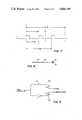
- FIG. 8is a schematic representation of a plan view of the end of a bipolar pacing lead of the type with which the circuit of FIG. 1 is designed to be used.
- FIG. 9is an electrical schematic diagram of the bipolar/unipolar logic switch.
- FIG. 1illustrates in functional form the overall electronic circuit requirements for bipolar/unipolar pacing and programming in the pulse generator portion of an implantable cardiac pacer according to the invention.
- the electrical components of the pacerare intended to be powered by a two-cell lithium compound battery and sealed together with the battery cells in the customary biologically compatible hermetic enclosure such as a welded titanium case with an integral connector formed of tissue compatible epoxy.
- the pacer or pulse generator as it is often calledis implanted subcutaneously preferably in the pectoral, axilliary or abdominal regions.
- the pulse generatoris electrically interconnected with a pacer lead which extends through an opening in a nearby vein into the heart, terminating against the lower interior wall of the right ventricle.
- the circuitry of FIG. 1is designed to provide long term cardiac pacing while offering the physician the option of being able to alter the load, lead configuration and sensitivity as well as the output current and fixed rate of the implanted pacer.
- a cardiac pacer including the circuitry of FIG. 1 according to the inventionis being introduced to the market by Cordis Corporation, the assignee of the present application, under the trademark Multicor Gamma, Model No. 336A.
- the pacer parametersare designed to be altered by employing an external portable battery powered Model 222C Omnicor Programmer which emits electromagnet pulses in a code recognized by the pacer programming circuitry. Programming can be accomplished with the programmer at any time before, during or after implantation.
- circuitry of FIG. 1is designed to achieve the following programmable parameters.
- Sensitivity0.8, 1.5, 2.5, 3.0, 3.5, 4.0, 5.0 or 5.5 millivolts (mV)
- VVIR-wave inhibited
- VVTR-wave synchronous
- VOOasynchronous or fixed rate
- the pacer clock 10produces logic pulses at a steady rate. Clock pulses are counted by the programmable counter 12, which also divides the count by one of eight ratios before providing outputs to the logic gates 14 at fixed fractions of the pacers pulse to pulse interval.
- the logic gatesdevelop the refractory, noise sampling, and alert portions of the pacer timing cycle and also initiate the pacer output pulse at the appropriate time. These timing functions are similar to those found in commercially available Omnicor® pacers.
- the programmable sensing amplifier 16detects cardiac depolarizations and produces a logic pulse approximately 10 milliseconds wide each time the input signal exceeds the amplifier threshold in either the positive or negative direction.
- the signal/noise analyzer 18is activated for noise detection during the final portion of the refractory period. If electrical noise is received by the pacer during the refractory period, the analyzer provides a control signal that causes the pacer to complete the balance of the timing cycle and then produce an output pulse. If noise is not detected during the final portion of the refractory period, the analyzer 18 accepts single logic outputs from the sensing amplifier 16 at the beginning of the alert period. If such an output is received, the analyzer 18 resets the counter 12 and immediately begins a new timing cycle.
- the pace limit circuit 20measures the interval between pacer output pulses and limits the minimum spacing to approximately 400 ms. Thus, if the output pulse rate tends to increase because of a circuit malfunction, for example, the maximum rate will be limited to approximately 150 ppm. At approximately 150 ppm, the pace limit circuit is designed to block 2:1, to produce an actual rate of approximately 75 ppm. If the internal rate continues to increase, the pace limit circuit will again operate to allow the actual output rate to increase up to approximately 150 ppm and then will block 3:1. Higher internal rates will be blocked proportionately 4:1, 5:1 etc., to always limit the output pulse rate to approximately 150 ppm. The abrupt decrease in rate following an increase in rate provides an indication to the patient that the pace limit circuit has been activated.
- the pace limit functionis independent of the other pacer circuits and has no effect on normal pacer operation. However, in the VVT mode, the pace limit circuit prevents stimulation at rates above 150 ppm caused, for example, by the patient's intrinsic heart rate or by an external pacer.
- FIG. 1The remaining components of FIG. 1 accomplish the setting of the various parameter values set forth above. Magnetic pulse trains from an external programmer actuate the reed switch 22 during each programming transmission sequence, causing voltage pulses to be conducted to the timing circuits 24 and 26 and pulse counters 28 and 30. Two successive programming transmissions are required to set all programmable parameters.
- the programmer used in connection with the pacer circuitry of FIG. 1differs from prior Cordis Omnicor® programmers only in the provision of selectable means for generating pulses at twice the normal rate of 3 ms. By design, in the first transmission, pulses occur at a pulse repetition period of approximately 3.0 ms; in the second transmission, the pulse repetition period is 1.5 ms.
- Rate and output currentare programmed during the first lower frequency transmission.
- the 3 ms pulsesare counted in binary pulse counter 28.
- the counters 28 and 30cannot be activated until eight pulses have been received at the respective pulse repetition rate.
- counter 28may count up to 32 successive pulses 3 ms apart. The sum of the pulses counted at the first frequency determines which of the five binary output lines of decoder 32 will be activated. Three of the output lines are used to set the programmable counter for rate programming, and two of the lines are used to establish the output current level by setting the operating characteristics of the output driver circuit 34.
- the voltage pulses from the reed switch 22are passed by the timing circuit 26 and counted in the other binary counter 30, once enabled by the reception of eight initial pulses.
- Counter 30is designed to count up to 128 successive pulses. The sum determines which of the seven binary output lines of decoder 36 will be activated.
- One output line of decoder 36determines circuit configuration by setting logic switch 38 to designate the anode.
- Another linedetermines the high or low range of the frequency adjust circuit 40.
- Clock 10is an RC controlled oscillator whose inherent period of oscillation is determined by a discharge of current.
- Frequency adjust circuit 40causes more or less current to be drained from the discharge circuit so as to set the output frequency of the clock 10 at a higher level or a lower level. As a consequence, all of the intervals established by the programmable counter 12 and logic gates 14 are automatically adjusted to a high or a low range.
- the resulting fixed rate output of the paceris one of the two-clock frequencies (high rate range or low rate range) as determined by frequency adjust circuit 40, divided by one of eight programmable counter ratios selected via decoder 32 in the first transmission. Three binary output lines of the decoder 36 determine the sensitivity of the pacer to natural cardiac activity.
- Sensitivityis programmed by setting the attenuator 42 to one of eight levels by manipulating a bank of resistors with electronic switches or transmission gates responsive to the binary output lines. The remaining two lines from the decoder 36 determine the pacing mode. If the VOO mode set line is high, the sense amplifier 16 is disabled thus making the pacer independent of natural cardiac activity. The other binary output line of decoder 36 selects VVI or VVT mode. In the normal VVI mode, an R-wave occurring during the alert period as sensed by the sense amplifier 16 restarts the timing cycle without stimulation. This is the normal demand mode or Stanicor® mode of operation.
- the sensing of an R-wave during the alert periodcauses the pacer to superimpose instantaneously a stimulation pulse as well as restarting the timing cycle.
- a brief interval at the start of the alert periodis arranged to inhibit stimulation while resetting the timing interval.
- the timing circuits 24 and 26 at the inputs to the program counters 28 and 30are safety devices. They are activated when the first magnetic pulse of each pulse train is received. If another pulse does not occur within approximately 3 ms (or 1.5 ms), the timing circuits will turn off the counters and hold the program decoder output lines in the previously programmed state. Thus, stray magnetic pulses from the environment cannot by themselves change the program. As in the Terry patent, an enable counter precedes the program counter/decoder circuit. Thus, it is the enable counter which is reset and not the program counter/decoder, when another pulse does not occur within the required pulse period.
- Multi-frequency programmingrequires frequency discrimination in the programming circuits. This is accomplished by the timing circuitry 24 and 26 which is shown in more detail in FIG. 2.
- One side of the reed switch 22is connected to positive voltage V DD .
- the other sideis connected by an isolation resistor R1 and an RC debounce filter 50 to the input of a Schmitt trigger 52 which accomplishes the necessary pulse shaping.
- Debounce filter 50comprises capacitor C1 and resistor R2 connected in parallel from the junction of resistor R1 and Schmitt trigger 52 to ground V SS .
- the performance characteristics of the filterare determined by the value of capacitor C1 which in the preferred embodiment is 470 picofarads.
- the discharge time constantmust be fast in order for the input signal to return below the threshold before the next pulse.
- the time constantis determined by setting the resistor value R2, preferably approximately 500 kilohms.
- Resistor R1is preferably about 1 kilohm to isolate V SS from V DD .
- the dual frequency programming systemnecessitates the respective counters 28 and 30 be programmed independently at 3 and 1.5 ms respectively. For this reason, it is necessary that the tolerances of the bandpass circuitry be chosen with care.
- the output of the Schmitt trigger 52is a series of pulses at either 3.0 ms or 1.5 ms.
- timing circuitry 26is implemented by means of an analog one-shot and missing pulse detector 54.
- the bandpass characteristics of this analog filterare determined by the RC time constants in these two conventional circuits (not shown).
- the leading edge of the program input signaltriggers the one-shot as shown in FIGS. 3 thru 6.
- the missing pulse detectorbegins to discharge the voltage level.
- the enable counter(not shown) is reset so that programming cannot occur. This corresponds to the condition where the pulse repetition rate is too low as in FIG. 5. If the leading edge of the next pulse occurs when the one shot is still high, the pulse is not counted as shown in FIG. 6. If the leading edge of the next pulse occurs before the decaying voltage reaches the threshold level, the oneshot is retriggered and the counter is advanced as shown in normal operation in FIG. 4.
- the band width for the 1.5 ms pulsesIt has been determined that the optimum band width for the 1.5 ms pulses using this system of detector 54 is 465 to 1250 hertz (Hz).
- the lower frequency pulses discriminated by timing circuitry 24are passed through a corresponding digital bandpass filter 56.
- the digital bandpass filteras shown in FIG. 7, is designed to cause the enable counter to be reset unless the pulse interval is between 2.3 ms and 4.6 ms corresponding to a lower bandpass of 215 to 434 Hz.
- the digital bandpass filtermay be implemented by employing a special counter which counts clock pulses from a special program clock preferably having a rate of approximately 1613 Hz.
- the counteris enabled by the leading edge of the first magnetic programming pulse.
- the leading edge of the next programming pulsesamples the count and resets the counter. If the sampled count is 4, 5, 6 or 7 clock pulses, the pulse interval is acceptable. If the sampled count is anything other than 4 through 7, the enable counter is reset thus retaining the previous count in the program counter.
- a suitable bipolar pacing leadcomprises a pair of conductors extending through a polyurethane insulating sheath 60 terminating in a cathode tip 62 made of platinum-irridium.
- a cathode tip 62made of platinum-irridium.
- collapsible silastic fins 64help anchor the pacer lead in the trebeculae of the heart chamber.
- a ring electrode 66also of platinum-irridium is available to serve as a remote anode.
- the electrodes 62 and 66 on the pacer leadare electrically connected to the ends of the respective conductors in the sheath 60.
- the unipolar/bipolar logic switch 38can be implemented by switching the connection of positive voltage V DD to the case of the implanted pulse generator or the remote anode 66 of FIG. 8.
- the single bit output line from decoder 36 to the logic switch 38is divided into a pair of complementary outputs to control the gates of two p-channel V-MOS or D-MOS fuel defect transistors of the type available from Supertex, Inc. This type of transistor is chosen as an electronic switch because of its extraordinarily low drain to source "ON" resistance since it will be in series with the heart's impedance.
- the multi-frequency programming system described aboveis not limited to dual frequency programming. It may be extended to any number of frequencies so long as suitable bandpass filter arrangements can be made.
- the multi-frequency programming systemoffers the capability of increasing the transmitted data to the pulse generator without increasing the number of programming pulses at one frequency.
- the systemis thus particularly suitable for adding programmable functions to a given pacer. By adjusting the passband, the new programmable functions can be implemented affecting the operation of the original programming system.
Landscapes
- Health & Medical Sciences (AREA)
- Life Sciences & Earth Sciences (AREA)
- Biophysics (AREA)
- Heart & Thoracic Surgery (AREA)
- Engineering & Computer Science (AREA)
- Biomedical Technology (AREA)
- Nuclear Medicine, Radiotherapy & Molecular Imaging (AREA)
- Radiology & Medical Imaging (AREA)
- Animal Behavior & Ethology (AREA)
- General Health & Medical Sciences (AREA)
- Public Health (AREA)
- Veterinary Medicine (AREA)
- Electrotherapy Devices (AREA)
Abstract
Description
Claims (6)
Priority Applications (1)
| Application Number | Priority Date | Filing Date | Title |
|---|---|---|---|
| US06/753,593US4606349A (en) | 1981-08-10 | 1985-07-10 | Implantable cardiac pacer having dual frequency programming and bipolar/unipolar lead programmability |
Applications Claiming Priority (2)
| Application Number | Priority Date | Filing Date | Title |
|---|---|---|---|
| US29143081A | 1981-08-10 | 1981-08-10 | |
| US06/753,593US4606349A (en) | 1981-08-10 | 1985-07-10 | Implantable cardiac pacer having dual frequency programming and bipolar/unipolar lead programmability |
Related Parent Applications (1)
| Application Number | Title | Priority Date | Filing Date |
|---|---|---|---|
| US06/618,767DivisionUS4561444A (en) | 1981-08-10 | 1984-06-11 | Implantable cardiac pacer having dual frequency programming and bipolar/linipolar lead programmability |
Publications (1)
| Publication Number | Publication Date |
|---|---|
| US4606349Atrue US4606349A (en) | 1986-08-19 |
Family
ID=26966764
Family Applications (1)
| Application Number | Title | Priority Date | Filing Date |
|---|---|---|---|
| US06/753,593Expired - LifetimeUS4606349A (en) | 1981-08-10 | 1985-07-10 | Implantable cardiac pacer having dual frequency programming and bipolar/unipolar lead programmability |
Country Status (1)
| Country | Link |
|---|---|
| US (1) | US4606349A (en) |
Cited By (41)
| Publication number | Priority date | Publication date | Assignee | Title |
|---|---|---|---|---|
| US4741342A (en)* | 1986-03-11 | 1988-05-03 | Intermedics, Inc. | Cardiac pacemaker with selective unipolar/bipolar pacing |
| EP0358337A1 (en)* | 1988-08-29 | 1990-03-14 | Intermedics Inc. | Method and apparatus for assuring pacer programming is compatible with the lead |
| EP0338363A3 (en)* | 1988-04-19 | 1991-05-08 | Pacesetter AB | Configuration programming of an implantable pacemaker |
| US5897577A (en)* | 1997-11-07 | 1999-04-27 | Medtronic, Inc. | Pacing lead impedance monitoring circuit and method |
| WO1999024112A1 (en) | 1997-11-07 | 1999-05-20 | Medtronic, Inc. | Non-physiologic sense detection for implantable medical devices |
| US6317633B1 (en) | 1999-01-19 | 2001-11-13 | Medtronic, Inc. | Implantable lead functional status monitor and method |
| WO2002018009A1 (en) | 2000-08-26 | 2002-03-07 | Medtronic, Inc. | Implantable lead functional status monitor and method |
| US6445952B1 (en) | 2000-05-18 | 2002-09-03 | Medtronic, Inc. | Apparatus and method for detecting micro-dislodgment of a pacing lead |
| US6721600B2 (en) | 2000-01-19 | 2004-04-13 | Medtronic, Inc. | Implantable lead functional status monitor and method |
| US20040162591A1 (en)* | 2003-02-15 | 2004-08-19 | Medtronic, Inc. | Impedance measurement in implanted device |
| US20070173890A1 (en)* | 2006-01-24 | 2007-07-26 | Cyberonics, Inc. | Stimulation mode adjustment for an implantable medical device |
| US20070173910A1 (en)* | 2006-01-24 | 2007-07-26 | Cyberonics, Inc. | Input response override for an implantable medical device |
| US20070255374A1 (en)* | 2006-04-28 | 2007-11-01 | Cyberonics, Inc. | Compensation reduction in tissue stimulation therapy |
| US7489561B2 (en) | 2005-10-24 | 2009-02-10 | Cyberonics, Inc. | Implantable medical device with reconfigurable non-volatile program |
| US20090112292A1 (en)* | 2007-10-26 | 2009-04-30 | Cyberonics Inc. | Dynamic lead condition detection for an implantable medical device |
| US20090125079A1 (en)* | 2007-10-26 | 2009-05-14 | Cyberonics Inc. | Alternative operation mode for an implantable medical device based upon lead condition |
| US7567840B2 (en) | 2005-10-28 | 2009-07-28 | Cyberonics, Inc. | Lead condition assessment for an implantable medical device |
| US20090192567A1 (en)* | 2008-01-25 | 2009-07-30 | Armstrong Randolph K | Method, Apparatus and System for Bipolar Charge Utilization During Stimulation by an Implantable Medical Device |
| US20090270943A1 (en)* | 2008-04-25 | 2009-10-29 | Maschino Steven E | Blocking Exogenous Action Potentials by an Implantable Medical Device |
| US7869885B2 (en) | 2006-04-28 | 2011-01-11 | Cyberonics, Inc | Threshold optimization for tissue stimulation therapy |
| US7869867B2 (en) | 2006-10-27 | 2011-01-11 | Cyberonics, Inc. | Implantable neurostimulator with refractory stimulation |
| US7974707B2 (en) | 2007-01-26 | 2011-07-05 | Cyberonics, Inc. | Electrode assembly with fibers for a medical device |
| US7974701B2 (en) | 2007-04-27 | 2011-07-05 | Cyberonics, Inc. | Dosing limitation for an implantable medical device |
| US8150508B2 (en) | 2006-03-29 | 2012-04-03 | Catholic Healthcare West | Vagus nerve stimulation method |
| US8180462B2 (en) | 2006-04-18 | 2012-05-15 | Cyberonics, Inc. | Heat dissipation for a lead assembly |
| WO2012170325A2 (en) | 2011-06-09 | 2012-12-13 | Medtronic, Inc. | Method and apparatus to manage lead-related conditions for fault tolerance enhancements |
| US8457747B2 (en) | 2008-10-20 | 2013-06-04 | Cyberonics, Inc. | Neurostimulation with signal duration determined by a cardiac cycle |
| US8463384B2 (en) | 2011-01-27 | 2013-06-11 | Medtronic, Inc. | Isolated lead conductor measurements for fault detection |
| US8478420B2 (en) | 2006-07-12 | 2013-07-02 | Cyberonics, Inc. | Implantable medical device charge balance assessment |
| US8478428B2 (en) | 2010-04-23 | 2013-07-02 | Cyberonics, Inc. | Helical electrode for nerve stimulation |
| US8483846B2 (en) | 2006-07-26 | 2013-07-09 | Cyberonics, Inc. | Multi-electrode assembly for an implantable medical device |
| US8565867B2 (en) | 2005-01-28 | 2013-10-22 | Cyberonics, Inc. | Changeable electrode polarity stimulation by an implantable medical device |
| US8577457B2 (en) | 2011-07-07 | 2013-11-05 | Medtronics, Inc. | Isolating lead body for fault detection |
| US8855765B2 (en) | 2011-06-09 | 2014-10-07 | Medtronic, Inc. | Fault tolerant methods and architectures for embedded intelligence in medical leads |
| WO2015123483A1 (en) | 2014-02-13 | 2015-08-20 | Medtronic, Inc. | Lead monitoring frequency based on lead and patient characteristics |
| US9232898B2 (en) | 2011-10-27 | 2016-01-12 | Medtronic, Inc. | Method and apparatus to manage lead-related conditions for fault tolerance enhancements |
| US9314633B2 (en) | 2008-01-25 | 2016-04-19 | Cyberonics, Inc. | Contingent cardio-protection for epilepsy patients |
| US9539428B2 (en) | 2011-01-27 | 2017-01-10 | Medtronic, Inc. | Isolating lead conductor for fault detection |
| US10653883B2 (en) | 2009-01-23 | 2020-05-19 | Livanova Usa, Inc. | Implantable medical device for providing chronic condition therapy and acute condition therapy using vagus nerve stimulation |
| US11633597B2 (en) | 2008-01-25 | 2023-04-25 | Flint Hills Scientific, Llc. | Contingent cardio-protection for epilepsy patients |
| US11766565B2 (en) | 2008-01-25 | 2023-09-26 | Flint Hills Scientific, L.L.C. | Contingent cardio-protection for epilepsy patients |
Citations (2)
| Publication number | Priority date | Publication date | Assignee | Title |
|---|---|---|---|---|
| EP0030897A1 (en)* | 1979-12-18 | 1981-06-24 | Cardiofrance- Compagnie Francaise D'electrocardiologie | Polyvalent implantable cardiac pacemaker |
| US4416282A (en)* | 1981-03-02 | 1983-11-22 | Cordis Corporation | Cardiac pacer with improved, output circuitry |
- 1985
- 1985-07-10USUS06/753,593patent/US4606349A/ennot_activeExpired - Lifetime
Patent Citations (2)
| Publication number | Priority date | Publication date | Assignee | Title |
|---|---|---|---|---|
| EP0030897A1 (en)* | 1979-12-18 | 1981-06-24 | Cardiofrance- Compagnie Francaise D'electrocardiologie | Polyvalent implantable cardiac pacemaker |
| US4416282A (en)* | 1981-03-02 | 1983-11-22 | Cordis Corporation | Cardiac pacer with improved, output circuitry |
Cited By (69)
| Publication number | Priority date | Publication date | Assignee | Title |
|---|---|---|---|---|
| US4741342A (en)* | 1986-03-11 | 1988-05-03 | Intermedics, Inc. | Cardiac pacemaker with selective unipolar/bipolar pacing |
| EP0338363A3 (en)* | 1988-04-19 | 1991-05-08 | Pacesetter AB | Configuration programming of an implantable pacemaker |
| EP0358337A1 (en)* | 1988-08-29 | 1990-03-14 | Intermedics Inc. | Method and apparatus for assuring pacer programming is compatible with the lead |
| US5897577A (en)* | 1997-11-07 | 1999-04-27 | Medtronic, Inc. | Pacing lead impedance monitoring circuit and method |
| WO1999024113A1 (en) | 1997-11-07 | 1999-05-20 | Medtronic, Inc. | Pacing lead impedance monitoring circuit and method |
| WO1999024112A1 (en) | 1997-11-07 | 1999-05-20 | Medtronic, Inc. | Non-physiologic sense detection for implantable medical devices |
| US5910156A (en)* | 1997-11-07 | 1999-06-08 | Medtronic Inc. | Non-physiologic sense detection for implantable medical devices |
| US6317633B1 (en) | 1999-01-19 | 2001-11-13 | Medtronic, Inc. | Implantable lead functional status monitor and method |
| US6721600B2 (en) | 2000-01-19 | 2004-04-13 | Medtronic, Inc. | Implantable lead functional status monitor and method |
| US6445952B1 (en) | 2000-05-18 | 2002-09-03 | Medtronic, Inc. | Apparatus and method for detecting micro-dislodgment of a pacing lead |
| WO2002018009A1 (en) | 2000-08-26 | 2002-03-07 | Medtronic, Inc. | Implantable lead functional status monitor and method |
| WO2004073795A1 (en)* | 2003-02-15 | 2004-09-02 | Medtronic Inc. | Impedance measurement in implanted device |
| US7233825B2 (en) | 2003-02-15 | 2007-06-19 | Medtronic, Inc. | Impedance measurement in implanted device |
| US20040162591A1 (en)* | 2003-02-15 | 2004-08-19 | Medtronic, Inc. | Impedance measurement in implanted device |
| US8565867B2 (en) | 2005-01-28 | 2013-10-22 | Cyberonics, Inc. | Changeable electrode polarity stimulation by an implantable medical device |
| US9586047B2 (en) | 2005-01-28 | 2017-03-07 | Cyberonics, Inc. | Contingent cardio-protection for epilepsy patients |
| US7489561B2 (en) | 2005-10-24 | 2009-02-10 | Cyberonics, Inc. | Implantable medical device with reconfigurable non-volatile program |
| US8532773B2 (en) | 2005-10-28 | 2013-09-10 | Cyberonics, Inc. | Lead condition assessment for an implantable medical device |
| US7567840B2 (en) | 2005-10-28 | 2009-07-28 | Cyberonics, Inc. | Lead condition assessment for an implantable medical device |
| US8190258B2 (en) | 2005-10-28 | 2012-05-29 | Cyberonics, Inc. | Lead condition assessment for an implantable medical device |
| US20090270959A1 (en)* | 2005-10-28 | 2009-10-29 | Cyberonics Inc. | Lead condition assessment for an implantable medical device |
| US7996079B2 (en) | 2006-01-24 | 2011-08-09 | Cyberonics, Inc. | Input response override for an implantable medical device |
| US20070173890A1 (en)* | 2006-01-24 | 2007-07-26 | Cyberonics, Inc. | Stimulation mode adjustment for an implantable medical device |
| US20070173910A1 (en)* | 2006-01-24 | 2007-07-26 | Cyberonics, Inc. | Input response override for an implantable medical device |
| US8280505B2 (en) | 2006-03-29 | 2012-10-02 | Catholic Healthcare West | Vagus nerve stimulation method |
| US8219188B2 (en) | 2006-03-29 | 2012-07-10 | Catholic Healthcare West | Synchronization of vagus nerve stimulation with the cardiac cycle of a patient |
| US8738126B2 (en) | 2006-03-29 | 2014-05-27 | Catholic Healthcare West | Synchronization of vagus nerve stimulation with the cardiac cycle of a patient |
| US8660666B2 (en) | 2006-03-29 | 2014-02-25 | Catholic Healthcare West | Microburst electrical stimulation of cranial nerves for the treatment of medical conditions |
| US9108041B2 (en) | 2006-03-29 | 2015-08-18 | Dignity Health | Microburst electrical stimulation of cranial nerves for the treatment of medical conditions |
| US8615309B2 (en) | 2006-03-29 | 2013-12-24 | Catholic Healthcare West | Microburst electrical stimulation of cranial nerves for the treatment of medical conditions |
| US8150508B2 (en) | 2006-03-29 | 2012-04-03 | Catholic Healthcare West | Vagus nerve stimulation method |
| US9533151B2 (en) | 2006-03-29 | 2017-01-03 | Dignity Health | Microburst electrical stimulation of cranial nerves for the treatment of medical conditions |
| US9289599B2 (en) | 2006-03-29 | 2016-03-22 | Dignity Health | Vagus nerve stimulation method |
| US8180462B2 (en) | 2006-04-18 | 2012-05-15 | Cyberonics, Inc. | Heat dissipation for a lead assembly |
| US7869885B2 (en) | 2006-04-28 | 2011-01-11 | Cyberonics, Inc | Threshold optimization for tissue stimulation therapy |
| US20070255374A1 (en)* | 2006-04-28 | 2007-11-01 | Cyberonics, Inc. | Compensation reduction in tissue stimulation therapy |
| US7962220B2 (en) | 2006-04-28 | 2011-06-14 | Cyberonics, Inc. | Compensation reduction in tissue stimulation therapy |
| US8478420B2 (en) | 2006-07-12 | 2013-07-02 | Cyberonics, Inc. | Implantable medical device charge balance assessment |
| US8483846B2 (en) | 2006-07-26 | 2013-07-09 | Cyberonics, Inc. | Multi-electrode assembly for an implantable medical device |
| US7869867B2 (en) | 2006-10-27 | 2011-01-11 | Cyberonics, Inc. | Implantable neurostimulator with refractory stimulation |
| US8295946B2 (en) | 2007-01-26 | 2012-10-23 | Cyberonics, Inc. | Electrode assembly with fibers for a medical device |
| US7974707B2 (en) | 2007-01-26 | 2011-07-05 | Cyberonics, Inc. | Electrode assembly with fibers for a medical device |
| US8306627B2 (en) | 2007-04-27 | 2012-11-06 | Cyberonics, Inc. | Dosing limitation for an implantable medical device |
| US7974701B2 (en) | 2007-04-27 | 2011-07-05 | Cyberonics, Inc. | Dosing limitation for an implantable medical device |
| US20090125079A1 (en)* | 2007-10-26 | 2009-05-14 | Cyberonics Inc. | Alternative operation mode for an implantable medical device based upon lead condition |
| US20090112292A1 (en)* | 2007-10-26 | 2009-04-30 | Cyberonics Inc. | Dynamic lead condition detection for an implantable medical device |
| US8868203B2 (en) | 2007-10-26 | 2014-10-21 | Cyberonics, Inc. | Dynamic lead condition detection for an implantable medical device |
| US8942798B2 (en) | 2007-10-26 | 2015-01-27 | Cyberonics, Inc. | Alternative operation mode for an implantable medical device based upon lead condition |
| US8260426B2 (en) | 2008-01-25 | 2012-09-04 | Cyberonics, Inc. | Method, apparatus and system for bipolar charge utilization during stimulation by an implantable medical device |
| US11766565B2 (en) | 2008-01-25 | 2023-09-26 | Flint Hills Scientific, L.L.C. | Contingent cardio-protection for epilepsy patients |
| US11633597B2 (en) | 2008-01-25 | 2023-04-25 | Flint Hills Scientific, Llc. | Contingent cardio-protection for epilepsy patients |
| US20090192567A1 (en)* | 2008-01-25 | 2009-07-30 | Armstrong Randolph K | Method, Apparatus and System for Bipolar Charge Utilization During Stimulation by an Implantable Medical Device |
| US9314633B2 (en) | 2008-01-25 | 2016-04-19 | Cyberonics, Inc. | Contingent cardio-protection for epilepsy patients |
| US8204603B2 (en) | 2008-04-25 | 2012-06-19 | Cyberonics, Inc. | Blocking exogenous action potentials by an implantable medical device |
| US20090270943A1 (en)* | 2008-04-25 | 2009-10-29 | Maschino Steven E | Blocking Exogenous Action Potentials by an Implantable Medical Device |
| US8874218B2 (en) | 2008-10-20 | 2014-10-28 | Cyberonics, Inc. | Neurostimulation with signal duration determined by a cardiac cycle |
| US8457747B2 (en) | 2008-10-20 | 2013-06-04 | Cyberonics, Inc. | Neurostimulation with signal duration determined by a cardiac cycle |
| US10653883B2 (en) | 2009-01-23 | 2020-05-19 | Livanova Usa, Inc. | Implantable medical device for providing chronic condition therapy and acute condition therapy using vagus nerve stimulation |
| US8478428B2 (en) | 2010-04-23 | 2013-07-02 | Cyberonics, Inc. | Helical electrode for nerve stimulation |
| US8463384B2 (en) | 2011-01-27 | 2013-06-11 | Medtronic, Inc. | Isolated lead conductor measurements for fault detection |
| US9539428B2 (en) | 2011-01-27 | 2017-01-10 | Medtronic, Inc. | Isolating lead conductor for fault detection |
| WO2012170325A2 (en) | 2011-06-09 | 2012-12-13 | Medtronic, Inc. | Method and apparatus to manage lead-related conditions for fault tolerance enhancements |
| US8855765B2 (en) | 2011-06-09 | 2014-10-07 | Medtronic, Inc. | Fault tolerant methods and architectures for embedded intelligence in medical leads |
| US8798751B2 (en) | 2011-06-09 | 2014-08-05 | Medtronic, Inc. | Method and apparatus to manage lead-related conditions for fault tolerance enhancements |
| US8577457B2 (en) | 2011-07-07 | 2013-11-05 | Medtronics, Inc. | Isolating lead body for fault detection |
| US8751000B2 (en) | 2011-07-07 | 2014-06-10 | Medtronic, Inc. | Isolating lead body for fault detection |
| US9232898B2 (en) | 2011-10-27 | 2016-01-12 | Medtronic, Inc. | Method and apparatus to manage lead-related conditions for fault tolerance enhancements |
| US9750932B2 (en) | 2011-10-27 | 2017-09-05 | Medtronic, Inc. | Method and apparatus to manage lead-related conditions for fault tolerance enhancements |
| WO2015123483A1 (en) | 2014-02-13 | 2015-08-20 | Medtronic, Inc. | Lead monitoring frequency based on lead and patient characteristics |
Similar Documents
| Publication | Publication Date | Title |
|---|---|---|
| US4606349A (en) | Implantable cardiac pacer having dual frequency programming and bipolar/unipolar lead programmability | |
| US4561444A (en) | Implantable cardiac pacer having dual frequency programming and bipolar/linipolar lead programmability | |
| US5441525A (en) | Pacemaker with vasovagal syncope detection | |
| US4548209A (en) | Energy converter for implantable cardioverter | |
| AU596933B2 (en) | Oxygen sensing pacemaker | |
| US4532931A (en) | Pacemaker with adaptive sensing means for use with unipolar or bipolar leads | |
| US4390020A (en) | Implantable medical device and power source depletion control therefor | |
| US4401119A (en) | Prolongation of timing intervals in response to ectopic heart beats in atrial and ventricular pacemakers | |
| US4595009A (en) | Protection circuit for implantable cardioverter | |
| US4903701A (en) | Oxygen sensing pacemaker | |
| EP0058606B1 (en) | Atrial and ventricular pacemaker | |
| US6934585B1 (en) | System and method for far-field R-wave detection | |
| US5282838A (en) | Dual chamber cardiac pacemaker employing hysteresis to maximize the number of normally conducted ventricular beats with an optimum A-V delay for paced ventricular beats | |
| US5741308A (en) | Dual-chamber implantable pacemaker and method of operating same for automatically setting the pacemaker's AV interval as a function of a natural measured conduction time | |
| US6122546A (en) | Pacemaker and method of operating same that provides functional atrial cardiac pacing with ventricular support | |
| US5800472A (en) | Recommended replacement time trigger for use within an implantable rate-responsive pacemaker | |
| EP0313881B1 (en) | Rate-responsive pacemaker with variable hysteresis rate | |
| US6081747A (en) | Dual-chamber implantable pacemaker having negative AV/PV hysteresis and ectopic discrimination | |
| EP0753325B1 (en) | Improved upper rate response for implantable pacemaker based on atrial lock interval pacing | |
| US3433228A (en) | Multimode cardiac pacer | |
| EP0559193B1 (en) | Implantable pacemaker providing hysteresis in dual-chamber modes | |
| US3757792A (en) | Automatic threshold compensating demand pacemaker | |
| US6587723B1 (en) | Method and system for automatically measuring capture threshold in an implantable cardiac stimulation device | |
| EP0011942A2 (en) | Programmable cardiac pacemaker | |
| US7024241B1 (en) | Pacing pulse waveforms that support simultaneous intracardiac signal sensing and analysis |
Legal Events
| Date | Code | Title | Description |
|---|---|---|---|
| STCF | Information on status: patent grant | Free format text:PATENTED CASE | |
| AS | Assignment | Owner name:TELECTRONICS, N.V., DE RUYTERKADE 58A, CURACAO, NE Free format text:ASSIGNMENT OF ASSIGNORS INTEREST.;ASSIGNOR:TNC MEDICAL DEVICES PTE. LTD.;REEL/FRAME:004748/0373 Effective date:19870430 Owner name:TELECTRONICS, N.V., NAMIBIA Free format text:ASSIGNMENT OF ASSIGNORS INTEREST;ASSIGNOR:TNC MEDICAL DEVICES PTE. LTD.;REEL/FRAME:004748/0373 Effective date:19870430 | |
| AS | Assignment | Owner name:SOUTHEAST BANK, N.A., MIDLAD BANK PLC (SINGAPORE B Free format text:SECURITY INTEREST;ASSIGNOR:TELECTRONICS N.V.;REEL/FRAME:004748/0364 Effective date:19870612 | |
| AS | Assignment | Owner name:MIDLAND BANK PLC (SINGAPORE BRANCH) Free format text:SECURITY INTEREST;ASSIGNOR:TELECTRONICS N.V.;REEL/FRAME:004747/0217 Effective date:19870630 Owner name:CREDIT LYONNAIS (CAYMAN ISLANDS BRANCH) Free format text:SECURITY INTEREST;ASSIGNOR:TELECTRONICS N.V.;REEL/FRAME:004747/0217 Effective date:19870630 Owner name:SOUTHEAST BANK, N.A. Free format text:SECURITY INTEREST;ASSIGNOR:TELECTRONICS N.V.;REEL/FRAME:004747/0217 Effective date:19870630 | |
| AS | Assignment | Owner name:TELECTRONICS N.V., NETHERLANDS ANTILLES Free format text:RELEASED BY SECURED PARTY;ASSIGNOR:SOUTHEAST BANKN.A., MIDLAND BANK PLC AND CREDIT LYONNAIS;REEL/FRAME:005002/0786 Effective date:19880615 | |
| FPAY | Fee payment | Year of fee payment:4 | |
| AS | Assignment | Owner name:TELECTRONICS PACING SYSTEMS, INC., COLORADO Free format text:ASSIGNORS HEREBY CONFIRMS THE ENTIRE INTEREST IN SAID INVENTIONS TO ASSIGNEE ELECUTED ON SEPT. 16, 1988;ASSIGNORS:TELECTRONICS PTY. LTD.;MEDICAL TELECTRONICS HOLDING & FINANCE CO.;TELECTRONIC NV;AND OTHERS;REEL/FRAME:006172/0028 Effective date:19920622 | |
| FPAY | Fee payment | Year of fee payment:8 | |
| AS | Assignment | Owner name:TELECTRONICS PACING SYSTEMS, INC., COLORADO Free format text:CORRECTIVE ASSIGNMENT TO CORRECT ASSIGNEE'S STATE OF INCORPORATION. AN ASSIGNMENT WAS PREVIOUSLY RECORDED AT REEL 6172, FRAME 0028;ASSIGNORS:TELECTRONICS PTY. LTD., AN AUSTRALIAN COMPANY;MEDICAL TELECTRONICS HOLDING & FINANCE CO. (BV), A DUTCH COMPANY;TELECTRONICS NV, A COMPANY OF THE NETHERLANDS ANTILLES;AND OTHERS;REEL/FRAME:008321/0072 Effective date:19961101 | |
| AS | Assignment | Owner name:PACESETTER, INC., CALIFORNIA Free format text:ASSIGNMENT OF ASSIGNORS INTEREST;ASSIGNOR:TELECTRONICS PACING SYSTEMS;REEL/FRAME:008454/0461 Effective date:19961129 | |
| FPAY | Fee payment | Year of fee payment:12 |