US4605582A - Body support pad - Google Patents
Body support padDownload PDFInfo
- Publication number
- US4605582A US4605582AUS06/737,373US73737385AUS4605582AUS 4605582 AUS4605582 AUS 4605582AUS 73737385 AUS73737385 AUS 73737385AUS 4605582 AUS4605582 AUS 4605582A
- Authority
- US
- United States
- Prior art keywords
- body support
- support pad
- recited
- pad
- pod
- Prior art date
- Legal status (The legal status is an assumption and is not a legal conclusion. Google has not performed a legal analysis and makes no representation as to the accuracy of the status listed.)
- Expired - Lifetime
Links
Images


Classifications
- A—HUMAN NECESSITIES
- A61—MEDICAL OR VETERINARY SCIENCE; HYGIENE
- A61G—TRANSPORT, PERSONAL CONVEYANCES, OR ACCOMMODATION SPECIALLY ADAPTED FOR PATIENTS OR DISABLED PERSONS; OPERATING TABLES OR CHAIRS; CHAIRS FOR DENTISTRY; FUNERAL DEVICES
- A61G7/00—Beds specially adapted for nursing; Devices for lifting patients or disabled persons
- A61G7/05—Parts, details or accessories of beds
- A61G7/057—Arrangements for preventing bed-sores or for supporting patients with burns, e.g. mattresses specially adapted therefor
- A61G7/05707—Arrangements for preventing bed-sores or for supporting patients with burns, e.g. mattresses specially adapted therefor with integral, body-bearing projections or protuberances
- Y—GENERAL TAGGING OF NEW TECHNOLOGICAL DEVELOPMENTS; GENERAL TAGGING OF CROSS-SECTIONAL TECHNOLOGIES SPANNING OVER SEVERAL SECTIONS OF THE IPC; TECHNICAL SUBJECTS COVERED BY FORMER USPC CROSS-REFERENCE ART COLLECTIONS [XRACs] AND DIGESTS
- Y10—TECHNICAL SUBJECTS COVERED BY FORMER USPC
- Y10S—TECHNICAL SUBJECTS COVERED BY FORMER USPC CROSS-REFERENCE ART COLLECTIONS [XRACs] AND DIGESTS
- Y10S5/00—Beds
- Y10S5/944—Beds with upstanding firm massaging projections
- Y—GENERAL TAGGING OF NEW TECHNOLOGICAL DEVELOPMENTS; GENERAL TAGGING OF CROSS-SECTIONAL TECHNOLOGIES SPANNING OVER SEVERAL SECTIONS OF THE IPC; TECHNICAL SUBJECTS COVERED BY FORMER USPC CROSS-REFERENCE ART COLLECTIONS [XRACs] AND DIGESTS
- Y10—TECHNICAL SUBJECTS COVERED BY FORMER USPC
- Y10T—TECHNICAL SUBJECTS COVERED BY FORMER US CLASSIFICATION
- Y10T428/00—Stock material or miscellaneous articles
- Y10T428/24—Structurally defined web or sheet [e.g., overall dimension, etc.]
- Y10T428/24174—Structurally defined web or sheet [e.g., overall dimension, etc.] including sheet or component perpendicular to plane of web or sheet
- Y10T428/24182—Inward from edge of web or sheet
- Y—GENERAL TAGGING OF NEW TECHNOLOGICAL DEVELOPMENTS; GENERAL TAGGING OF CROSS-SECTIONAL TECHNOLOGIES SPANNING OVER SEVERAL SECTIONS OF THE IPC; TECHNICAL SUBJECTS COVERED BY FORMER USPC CROSS-REFERENCE ART COLLECTIONS [XRACs] AND DIGESTS
- Y10—TECHNICAL SUBJECTS COVERED BY FORMER USPC
- Y10T—TECHNICAL SUBJECTS COVERED BY FORMER US CLASSIFICATION
- Y10T428/00—Stock material or miscellaneous articles
- Y10T428/24—Structurally defined web or sheet [e.g., overall dimension, etc.]
- Y10T428/24628—Nonplanar uniform thickness material
- Y10T428/24661—Forming, or cooperating to form cells
Definitions
- a frequent malady of nonambulatory people such as people confined to beds or wheelchairsis that of the occurrence of decubitis ulcers, frequently referred to as pressure sores or bed sores.
- a major cause of the disorderis that conventional bedding and wheelchairs provide little in the way of either body support or reduces seating pressures. As there is little support or reduced pressure, the patient's weight exerted essentially constantly on tissue surrounding the skeletal structure can give rise to the formation of decubitus ulcers.
- Dynamic pads or cushionsare those which involve outside power sources to perform their function. Although such systems are convenient for bed confined patients, they are undesirable for wheelchair use due to their lack of mobility. In addition, such dynamic cushions are undesirable as they are relatively expensive.
- Static cushionsare generally preferred due to their being less expensive and their ability to provide mobility such as for use in wheelchairs.
- the static cushionscan be classed into two categories: (1) bladder type cushions and (2) foam cushions.
- Bladder type cushionsare basically flexible walled bags such as plastic bags which are filled with a fluid or some form of gel.
- the fluidcan be air or water.
- the gel filled bladdersare filled with some type of gel material such as ethylene glycol, polyethylene glycol, silicone, and the like.
- Bladder type cushionsare shown in U.S. Pat. No. 2,434,641 of Burns; and U.S. Pat. Nos. 3,605,145; 3,870,450; and 4,005,236, all of Graebe.
- the foam cushionscan be any structure using a piece of foam.
- foam cushionscan be solid pieces of foam or some type of foam laminate structure.
- foam type cushionsare the "egg crate" cushion and the contoured foam cushions.
- One cushionis disclosed in U.S. Pat. No. 3,231,454 of Williams.
- Foam cushionsare generally the least expensive type of cushion.
- the foam cushionsare undesirable in that they have a tendency to build up significant amounts of heat.
- a drawback with the build up of heatis that it is believed that heat buildup is a contributing factor to the occurrence of decubitus ulcers.
- the bladder productstend to be more expensive and tend to perform better in terms of pressure distribution. Some of the bladder products are low in weight like their counterparts in the foam cushion areas. Bladder products, like the foam cushions, also tend to cause tremendous heat buildup.
- Another drawback with bladder productsis that they tend to elevate the patient to a height greater than foam cushions.
- the invention hereinis directed to a body support pad which is relatively inexpensive, easy to manufacture, easy to clean, and which provides distribution of the pressure exerted on the pad so as to inhibit the formation of decubitus ulcers. More particularly, the body support pad herein is suited for use on wheelchairs for inhibiting the occurrence of decubitus ulcers on the patient confined to the wheelchair.
- the pad hereinis a body support pad which includes a flexible, generally planar base member which has an upper surface and a lower surface.
- the body support padis one integral structure which can be made by molding the pad from a moldable material such as a microcellular urethane.
- the padincludes a flexible, generally planar base member having an upper surface and a lower surface. Positioned along the lower surface is a plurality of pillars which extend outwardly from the lower surface.
- the plurality of pillarsis arranged in discrete arrays of individual pillars of similar pressure dispersion characteristics. That is, the pillars in any one particular array have the same pressure dispersing characteristics, which pressure dispersing characteristics can differ from the pillars in an adjacent or different array.
- the pillarsare provided such that they substantially evenly contact any supportive surface on which the pad is place when a body is supported on the pad. That is, the force of a person positioned on the pad displaces the flexible, planar base and the pillars generally all contact the supportive surface and begin to deflect themselves to provide a generally even distribution of the pressure across the entire plurality of pillars.
- a plurality of hollow podsextend outwardly from the upper surface of the flexible, generally planar base.
- the podsare generally conical with generally hemsipherically shaped upper portions.
- the podsare adapted to provide as great a surface area as possible for contacting a body supported on the pad in order to displace or disperse the force of the body on the pad over the greatest surface area.
- the podscan be slit so that when the pods collapse upon exertion of a force thereupon, a greater surface area remains in contact with the body compressing the pods.
- the podsare arranged in discrete arrays across the upper surface of the pad base member.
- the pods in each arrayhave a pressure dispersing characteristic which is uniform within the array but which differs from the pressure dispersing characteristics of the pods in any other array.
- the pods in a particular arrayprovide a resistive force to the body being supported on the pad and the pods are designed to provide such a resistive force generally normal to the body.
- the pillarsare hollow and arranged in any sufficient number of arrays corresponding to the differing number of force location points of the patient's body when positioned on a supporting surface.
- five arraysprovide the optimum beneficial properties of pressure distribution. That is, five differing types of pillars with five unique pressure dispersing characteristics are arrayed across the lower surface of the base member of the pad.
- the pressure dispersing characteristics of the pillarscan be attenuated by changing the height and wall thickness of each individual pillar.
- the podsare generally conical shaped with a generally rounded or hemispereically shaped apex.
- the podsare arrayed in a sufficient number of arrays to provide the beneficial properties and pressure dispersing characteristics based upon the body and how it is supported.
- the pressure dispersing characteristics of each podcan be attenuated by modifying the wall thickness of each pod.
- the podsare generally cylindrical or frustoconical in shape with a hemispherically shaped upper surface. Both the wall thickness of the cylindrical portion and the wall thickness of the hemispherically shaped portion can be modified to adjust the pressure dispersing characteristics of each pod.
- the pad hereinis also provided with ventilation apertures which extend through the base member and, more particularly, which extend through the end walls of the respective pillars and pods. It is desirable to provide the ventilation apertures to permit the free flow of air which aids in the reduction of heat buildup.
- the body support pad hereincan be easily molded of a lightweight material in a single molding step.
- the padcan be molded of an integral material as the pods and pillars are offset from one another.
- the pad hereincan be constructed of a durable material which can be resistant to fecal and urinary contamination or other body fluids.
- the pad hereinalso provides a structure which can be further modified by an attendant or by the user to accommodate particular features of a patient. That is, the various pillars and pods (and particularly the pillars) can be modified by an attendant such as by contouring to fit the needs of a particular patient.
- the body support pad hereincan be part of a combined body support cushion. That is, a body support cushion can include the above-described body support pad and a foam pad overlay which rests on top of the pods of the body support pad.
- the foam overlayis a lightweight foam material which is an open cellular foam to provide additional ventilation to the patient.
- the foam padcan be further ventilated by providing ventilation apertures extending through the foam overlay. The foam overlay aids in increasing the surface area of the patient which contacts the pods and aids in increasing comfort to the person.
- a cushion coveris selected which has a wickability to transport moisture away from the body. It is also desirable to provide a cover which is knitted to have a two-way stretch to prevent hammocking. Hammocking is undesirable as it causes undue pressure forces on the body. It is also desirable to provide a cushion cover which is an open knit so as to enhance breathability of the material and air flow through the entire cushion structure.
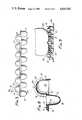
- FIG. 1is a perspective view of the body support pad herein;
- FIG. 2is a perspective exploded view of a patient support cushion utilizing the body support pad of FIG. 1;
- FIG. 3is a side elevational view of the body support pad of FIG. 1;
- FIG. 4is a top plan view of the body support pad of FIG. 1;
- FIG. 5is a diagramatic representation of the pod layout of the body support pad
- FIG. 6is a bottom plan view of the body support pad of FIG. 1;
- FIG. 7is a diagramatic view of the pillar placement for the body support pad
- FIG. 8is a cross-sectional view of the body support pad taken along lines 8--8 of FIG. 4;
- FIG. 9is a side elevational view of the body support pad illustrating how the body support pad supports a patient.
- the body support pad that is the subject of the invention hereinwill be described with regard to the accompanying drawings.
- the body support padwill be described with regard to a body support pad 10 shown in FIG. 1 designed for use as a seating pad. That is the body support pad 10 shown in FIG. 1 can be used as a seating pad for use in wheelchairs or on chairs and the like.
- the description herein with regard to the seating padcan be applicable to a pad which can be used for a reclining person such as a mattress pad and the like.
- the body support pad that is the subject of the invention hereinwill be described with regard to a seating pad as shown in the accompanying drawings.
- a body support padis constructed of an integrally molded microcellular urethane elastomer having a durometer of about 20 to 40 on the Shore A scale.
- the body support padis molded from a urethane microcellular urethane elastomer having a density in its molded form of about 0.40.
- Other moldable materialscan be used for constructing the body support pad but it has been found that a microcellular urethane elastomer is the preferred material as it provides a pad which is light in weight, provides good distribution of seating pressures, can be easily ventilated, is durable, and generally resistant to body fluids.
- the body support pad 10includes a generally flexible base member 12 which extends generally in a plane and which has an upper surface 14 and a lower surface 16. Extending upwardly from the upper surface 14 is a plurality of pods 18.
- the podsare generally cylindrical in shape with an upper hemisperical surface.
- the pods 18also include slits 20 along their sides so that the pods will compress in a substantially uniform manner upon a force being exerted upon them.
- the podsare integrally molded with the base member 12 and are generally hollow structures which are open on the lower surface 16 of the base member as can be more readily seen with regard to FIG. 6. With regard to FIG. 6, the pod cavity 25 can be seen which opens into the pods.
- the pillars 22provide contact with a supporting surface upon which the body support pad 10 is placed while the pods 18 provide contact with a body which rests or is supported by the body support pad 10.
- the pillars 22are also integrally molded from the material that constitutes the base member.
- the pillarsare also hollow structures which are open on the upper surface 14 of the base member through the pillar cavities 24 as can be seen in FIGS. 1 and 4. Also seen in the figures, the pillars and pods are offset from one another so that they can be readily molded and, as will be hereinafter discussed, to provide an acceptable pressure dispersion across the pad assembly.
- the embdoiment shown in FIG. 1there are 56 pods arrayed over the upper surface of the base member. There are 72 pillars arrayed over the lower surface of the base member. The number of pods and pillars can be varied, depending upon the use of the pad. It has been found herein that in order to provide the greatest surface area to support a body in a seating position, that 56 pods are preferred and 72 pillars are preferred for a body support pad being about 15 and 3/4 inches wide by about 17 and 3/4 inches deep and 2 and 5/8 inches in height.
- the base diameter for the podsbeing about 1 and 3/4 inches and their height about 1 and 1/8 inch with four slits 20 extending about one to one and one-eighth inches (1-11/8") in length.
- the pillarshave an opening radius of about 1 and 1/8 inches and range in a height from about 3/4 inch to 1 and 1/4 inch.
- the base memberhas a thickness of about 1/4 inch.
- a body support cushionis illustrated in an exploded view.
- the body support pad 10provides the basic pressure dispersing portion of the overall cushion assembly.
- a foam overlay 26Layered on the surface provided by the tops of the plurality of pods 18 is a foam overlay 26.
- the foam overlayis a foam pad which is about 1.8 pounds in density with a 30 indentation load deflection (ILD).
- the foam overlayhas a high resiliency and can be constructed of any suitable foaming material such as urethane, which is preferred. It is also preferred to have a foam material which is fire retardant in order to comply with most applicable fire regulations and codes. It is preferred to use an open celled foam structure in order to provide adequate ventilation for the body resting upon the cushion.
- a closed cell foamcan be used in situations wherein a slow memory for the foam overlay is desired. It has been herein that additional ventilation is preferred and such additional ventilation can be provided by placing ventilation apertures 28 through the foam overlay. By providing the ventilation apertures with a sufficient diameter, such as about 3/16 inch in diameter, the apertures remain open, even under loading so as to maintain adequate ventilation. In the preferred embodiment for a foam overlay, it was found that about 42 ventilation apertures could be provided, each with a diameter of about 1/8 to 3/16 inch.
- the foam overlayprovides an ability to increase the surface area which is in contact with the body and as the surface area is increased over that which could be provided by the individual pods, there is increased comfort to the body.
- the body support cushionalso includes a fabric cover 30 which extends over and around both the foam overlay 26 and the body support pad 10.
- the cover 30provides a means for maintaining the foam overlay on the body support pad.
- the coverprovides an upper surface 32 and a sidewall 34 which wraps and extends around the foam overlay and body support pad. It has been found that the cover should be selected from a material which provides wickability, the ability to transport moisture away from the body support by the pad. It is also desirable to provide a cover which will prevent or at least reduce what is commonly referred to as the hammocking effect.
- the hammocking effectis created by nonstretchable fabrics when a force or load is exerted upon them. Hammocking causes undue forces to be exerted upon a body.
- a preferred materialhas been found to be a 100% polypropylene which is readily wickable and which is a knitted fabric having a two-way stretch to reduce hammocking. It is also preferred to use an open knit to make the cover as an open knit increases breathability through the material of the cover and, therefore, increases air flow through the cushion assembly. The increased air flow or ventilation of the cushion assembly greatly aids in reducing or inhibiting the occurrence of decubitus ulcers. It is also desirable to provide a cover which will prevent or retard fires should the cover come into contact with a flame or embers such as can occur with fallen cigarettes.
- FIG. 3a side elevational view of the body support pad is illustrated.
- the pods 18are offset from the pillars 22. It has been found herein that by offsetting the pods from the pillars, a beneficial pressure distribution can be created.
- the side elevational view of FIG. 3also shows the slits 20 on the pods 18.
- the slits 20are placed about 90° apart on each pod, thus providing four slits for each pod.
- the slitsprovide a uniform deflection of each pod upon a force being exerted thereupon.
- the slitsalso provide an ability for the surface of the pod to maintain a relatively large surface area upon collapse which remains in contact with the body exerting the force and causing the collapse of each pod.
- FIG. 3also shows the ability of the pad herein to be ventilated by the appropriate ventilating apertures provided on the pad.
- the podscan include a pod ventilation aperture 38 at or along their upper curved surfaces and the pillars can be provided with a corresponding pillar ventilating aperture 40 on their curved surfaces.
- ventilation apertureswhich extend through the base member between the pods and pillars can be provided. The benefit of providing a wide variety of ventilation prevents undue heat buildup which has been found to be a contributory cause to the formation of decubitus ulcers.
- FIG. 4is a top plan view of the body support pad 10 showing the pods arrayed across the upper surface in an array that is 8 ⁇ 7 pods for a total of 56 pods. That is, the pods are arranged in 8 columns of 7 rows each.
- the podsthere are two discrete arrays of pods in which the pods have specific pressure dispersing characteristics with each of the two arrays having pods of differing pressure dispersing characteristics. All of the pods, however, have the four provided slits 20 regardless of their pressure dispersing characteristics.
- FIG. 5represents a preferred arrangement of the pods for a wheelchair pad wherein the body support pad is constructed of a molded, microcellular, urethane foam.
- the back of the body support padis at the top of the Figure. It has been found that two different arrays are sufficient to provide beneficial properties although more than two arrays can be utilized.
- a first array of podsextends generally along the three sides of the body support pad and about half-way up the center of the pad.
- the first array of podsis identified by the Roman Numeral I in the center of the schematically illustrated circles which are representative of the pods.
- the remaining pods identified by the Roman Numeral IIconstitute the second array of pods.
- the second array of podsis arrayed to represent the area of the body support pad which encounters the greatest force when supporting a body.
- the pods in the second arrayare less resistive and tend to disperse the forces to a greater extent throughout the pad than the pods in the first array.
- the pressure dispersing characteristics of the podsare controlled by the durometer of the material making up the pad, as well as by the wall thickness of the pod, both in the curved portion and the straight portion. This difference in sidewall thickness is illustrated in FIG. 8 which is a cross section of the body support pad. As can be seen in FIG.
- each pod 18has a pod sidewall 42 having a generally straight wall section designated as Section "a" and a curved wall section designated as Section "b.”
- the pressure dispersing characteristics of a podcan be varied.
- the pods in the first array Ihave a wall thickness in the curved wall section "b" of about 0.10 inch, and have a wall thickness in the straight wall section "a” of about 0.112 inch.
- the pods in the second array II which has a less pressure resistive characteristichave a wall thickness of about 0.10 inch in both the curved and straight wall sections.
- podsmeasuring 1 and 3/4 inches in diameter and having a height of about 1 and 1/8 inch with four slits each being about 1 and 1/8 inch in length.
- the basic shape and structure of the podshas been selected in order to provide the maximum surface area while providing beneficial pressure dispersing characteristics.
- the shapeswere selected based upon force/compression analysis performed on differing shaped structures utilizing different shapes, sizes, and thicknesses for pods.
- the preferred embodiment of the pod configurationwas based on the ability to provide maximum surface area at minimum deflection, to provide consistant load resistance at the widest range of compression forces, and to provide for a compression force that is both horizontal and diagonal as is the force from a patient's buttocks resting upon the pad.
- the selected dimensions and shape for the podsprovides a resistive force on the body supported by the pad.
- the pillar arrangement for the body support padis illustrated in the bottom plan view illustrated in FIG. 6.
- the pillars 22are arranged in an array of nine columns of eight rows each, for a total of 72 pillars for the wheelchair pad.
- the view shown in FIG. 6also shows the pod cavities 25 which illustrates the open, hollow structure of the pods.
- the pillarsare arranged in discrete arrays across the lower surface of the base member of the body support pad.
- the arrangement of the arraysis shown by the schematic representation of the pillars by the circles in FIG. 7.
- the back of the padis also indicated as being at the top of the figure illustrated.
- the pillarsare arranged in a plurality of arrays.
- the pillarsare arranged in five distinct arrays of pillars across the lower surface.
- the pillarsare provided in a height range from about 3/4 inch to about 1 and 1/4 inch and are provided with a wall thickness of from about 0.10 inch to about 0.175 inch. By selecting pillars within these ranges, varying pressure dispersing characteristics can be imparted to the individual pillars in a given array.
- the height of the pillarsis selected based upon the expected load or pressure to be exerted in any of the discrete areas of the pad.
- the body support padis constructed of a flexible material and the generally planar base member 12 will distort downwardly when a pressure is exerted on the upper surface. This downward distortion can be predicted by knowing how the body will be positioned on the upper surface. That is, there will be some areas of greater distortion than others. For this reason, the pillars are arranged in discrete arrays of individual pillars exhibiting certain pressure dispersing characteristics. In those areas where it is predicted that the base member will distort greatest, the pillar height is shortened and it is at its lowest height. In the areas where there will be little distortion, the pillars will have their greatest height.
- the pillarsare all adjusted in height such that when a load is placed upon the upper surface of the pad, all of the pillars will be in contact with the supporting surface upon which the body support pad rests. In this manner, the greatest dispersion of the pressure can be achieved.
- the pillarsare also provided with pressure dispersing characteristics by adjusting their wall thickness to provide an even collapse of all of the pillars when the expected load is placed upon the upper surface. That is, when the pillars are in contact with the support surface on which they rest, they exhibit a substantially even pressure resistive force. The collapse of the pillars disperses the load of the body and provides less resistive forces to the tuberosities of a patient (an area generally exhibiting greatest pressure) than to the surrounding tissue.
- the preferred body support pad having the above described physical dimensions with an array of 72 pillarshas five types of pillars arrayed over the lower surface.
- the five types of pillars with differing pressure dispersing characteristicsare identified by the letters A, B, C, D, and E.
- the array providing the least resistance but greatest pressure dispersing characteristicsis the discrete arrays identified by the letter C in FIG. 7.
- the two arrays identifiedcorrespond to the ischiam tuberosities of the patient.
- the ischiam tuberositiesare the two appendages which drop from the front of the hip bone and are generally the most frequent areas of pressure sores. On a patient, they are roughly four inches apart and protrude about 1 and 1/2 inches down from the main area of the pelvis.
- the padherein relieves pressures under the ischiam tuberosities to as low as possible, generally within the pressure range of about 20 to 40 millimeters of mercury (mm Hg).
- the pillarsare constructed of an open celled, microcellular urethane and have a height of about 0.75 inches and a wall thickness of about 0.10 inches.
- the pillars in this discrete arrayhave the shortest height of all the pillars as this area receives the greatest pressure from the patient's body and, therefore, the base member 12 deflects its greatest amount in this area.
- the next discrete array of pillarsis represented by the letter B in FIG. 7. These pillars exhibit a pressure dispersion slightly greater than the pillars designated as C.
- the pillars designated Bcorrespond to the coccyx and trochanter regions of a patient's body supported on the body support pad. These two areas exhibit the next greatest pressure and for this reason, it is desirable to prevent pressure buildup at the trochanter and coccyx areas.
- the pillars designated Bexhibit a pressure relief in the pressure range of about 10 to 30 millimeters of mercury.
- the pillars designated Bhave a height of about 1 inch and a wall thickness of 0.125 inches.
- the next distinct array of pillars exhibiting the next pressure relief valueare those designated as D in FIG. 7. These pillars correspond also to the area around the coccyx as well as the area adjacent the trochanter and leading to the posterior thigh region.
- the pillars designated Dhave a height of about 1.125 inches and a wall thickness of about 0.150 inches.
- the next array of pillarsare those designated by the letter E and are located at the front of the pad.
- the pillars designated Ecorrespond to the thigh region of the patient, whether the posterior or anterior region of the thighs. It is desirable to disperse some of the pressure into the thigh region as the fleshy part of the thighs can disperse the pressure load.
- the pillars designated as Ehave a height of about 1.125 inches and a wall thickness of about 1.25 inches.
- the array of pillars in FIG. 7 designated with the letter Aexhibits the greatest pressure resistance as it provides support for the body support pad.
- the array of pillars designated as Aextend generally along the sides of the pad as well as a small discrete array between the thighs of the patient.
- the pillars designated as Ahave a height of about 11/4 inches and a wall thickness of about 0.175 inches.
- the thigh areais the area that is capable of taking high seating pressures, however, care must be taken to insure proper postural positioning and, therefore, the thigh region contains both the A, E, and D type pillars.
- the surrounding tissueis ideal for pressure relief as it has a high fatty content and assures a good pressure distribution. For this reason, the greater resistive pillars designated as A are provided for such a surrounding tissue area.
- the body support padis designed to distribute the weight of a person to the thighs and surrounding tissue.
- the weightis transferred to the thighs and is generally substantially equally distributed between the anterior and posterior regions of the thighs.
- the padprovides acceptable lateral (side to side and front to back) stability by the arrangement of the pillars in order to aid maintaining a healthy posture and to provide stability to patients such as spinal cord injury patients.
- the arrays of the pillars with their differing pressure dispersing characteristicsare designed to collapse at different pressures and thereby distribute the seating pressures away from the tuberosities and coccyx and toward the thighs and surrounding tissues.
- An advantage of the design hereinis that the body support pad can be adjusted to accommodate the particular conditions of a patient. That is, the individual pillars can be cut to adjust their height and thereby their pressure dispersing characteristics for the individual needs of a patient.
- the body support padherein redistributes the pressure exerted upon it by a patient supported on the pad by a combination of resilient design and body contouring. That is, the individual pods and pillars are selected and their wall thickness adjusted to provide different resiliencies and the pillars are contoured (height adjusted) to accommodate the various portions of the patient's body which exhibit differing pressures.
- the body support pad hereincan be integrally molded in one easy step such as by the use of a reaction injection moldable, flexible, microcellular skinned, urethane foam material. The material is injection molded into the mold and then subsequently undergoes reaction to cure to form the open celled, microcellular, urethane structure. While molding the body support pad, the ventilation apertures can also be simultaneously molded to provide acceptable ventilation to the completed pad.
- FIG. 9is an illustration of the pad in use supporting a patient's body 48.
- the patient's bodyis supported by the pad and encounters and compresses the pods on the upper surface of the base member of the pad. As the pods are compressed, they provide a greater surface area which encounters the patient's body. That is, the hemispherical shape and the opening slots 19 (the slots expand or open upon pressure collapsing each pod) provide a greater surface area which is in contact with the body.
- the hemispherical shapealso exerts a pressure back on the body at about the same location where the force is exerted by the body on the pod.
- FIG. 9also shows the contouring or distortion of the base member 12.
- the pillarscome into contact with the support surface 46 upon which the body support pad rests.
- the shorter pillars in the areas representing the discrete arrays for the coccyx and ischiam tuberositiesencounter the support surface, but some of the initial force and pressure caused by the patient's body is initially absorbed in the flexing or distortion of the base member 12, thus spreading the force over the surface of the body support pad.
- the pillarstend to collapse or compress under the pressure of the patient's body, there is a generally even distribution as the pillars are all designed to further compress at about the same resistive forces. Initially the resistance is slight, then increases as the pillars collapse and more pillars come into contact and as more pillars start to compress due to the weight of the patient's body.
Landscapes
- Health & Medical Sciences (AREA)
- Nursing (AREA)
- Life Sciences & Earth Sciences (AREA)
- Animal Behavior & Ethology (AREA)
- General Health & Medical Sciences (AREA)
- Public Health (AREA)
- Veterinary Medicine (AREA)
- Invalid Beds And Related Equipment (AREA)
- Orthopedics, Nursing, And Contraception (AREA)
- Polarising Elements (AREA)
- Diaphragms For Electromechanical Transducers (AREA)
- Mattresses And Other Support Structures For Chairs And Beds (AREA)
Abstract
Description
Claims (34)
Priority Applications (8)
| Application Number | Priority Date | Filing Date | Title |
|---|---|---|---|
| US06/737,373US4605582A (en) | 1985-05-23 | 1985-05-23 | Body support pad |
| DE8686302724TDE3678198D1 (en) | 1985-05-23 | 1986-04-11 | CUSHION TO SUPPORT A BODY. |
| AT86302724TATE61726T1 (en) | 1985-05-23 | 1986-04-11 | CUSHION TO SUPPORT A BODY. |
| DE198686302724TDE202754T1 (en) | 1985-05-23 | 1986-04-11 | CUSHION TO SUPPORT A BODY. |
| EP86302724AEP0202754B1 (en) | 1985-05-23 | 1986-04-11 | Body support pad |
| CA000507743ACA1257934A (en) | 1985-05-23 | 1986-04-28 | Body support pad |
| JP61118359AJPH0634798B2 (en) | 1985-05-23 | 1986-05-22 | Body-support pad |
| US06/890,429US4673605A (en) | 1985-05-23 | 1986-07-25 | Body support pad |
Applications Claiming Priority (1)
| Application Number | Priority Date | Filing Date | Title |
|---|---|---|---|
| US06/737,373US4605582A (en) | 1985-05-23 | 1985-05-23 | Body support pad |
Related Child Applications (1)
| Application Number | Title | Priority Date | Filing Date |
|---|---|---|---|
| US06/890,429ContinuationUS4673605A (en) | 1985-05-23 | 1986-07-25 | Body support pad |
Publications (1)
| Publication Number | Publication Date |
|---|---|
| US4605582Atrue US4605582A (en) | 1986-08-12 |
Family
ID=24963663
Family Applications (1)
| Application Number | Title | Priority Date | Filing Date |
|---|---|---|---|
| US06/737,373Expired - LifetimeUS4605582A (en) | 1985-05-23 | 1985-05-23 | Body support pad |
Country Status (6)
| Country | Link |
|---|---|
| US (1) | US4605582A (en) |
| EP (1) | EP0202754B1 (en) |
| JP (1) | JPH0634798B2 (en) |
| AT (1) | ATE61726T1 (en) |
| CA (1) | CA1257934A (en) |
| DE (2) | DE202754T1 (en) |
Cited By (92)
| Publication number | Priority date | Publication date | Assignee | Title |
|---|---|---|---|---|
| USD307687S (en) | 1987-10-28 | 1990-05-08 | Span-America Medical Systems, Inc. | Mattress pad material |
| USD307689S (en) | 1987-11-19 | 1990-05-08 | Span-America Medical Systems, Inc. | Mattress pad material |
| USD307690S (en) | 1987-10-28 | 1990-05-08 | Span-America Medical Systems, Inc. | Mattress pad material |
| USD307688S (en) | 1987-12-04 | 1990-05-08 | Span-America Medical Systems, Inc. | Mattress pad material |
| USD308453S (en) | 1986-07-18 | 1990-06-12 | E. R. Carpenter Co., Inc. | Mattress |
| US4944060A (en)* | 1989-03-03 | 1990-07-31 | Peery John R | Mattress assembly for the prevention and treatment of decubitus ulcers |
| US4989284A (en)* | 1989-10-12 | 1991-02-05 | The Kendall Company | Cushion |
| US5031261A (en)* | 1990-03-15 | 1991-07-16 | E. R. Carpenter Company, Inc. | Mattress overlay for avoidance of decubitus ulcers |
| US5044031A (en)* | 1986-08-12 | 1991-09-03 | Philip R. Foster | Passive rewarming articles |
| USD323092S (en) | 1989-07-05 | 1992-01-14 | E. R. Carpenter Company, Inc. | Mattress overlay |
| USD325839S (en) | 1989-12-08 | 1992-05-05 | Woodbridge Foam Corporation | Pillow |
| USD325840S (en) | 1989-11-21 | 1992-05-05 | Woodbridge Foam Construction | Pillow |
| USD326204S (en) | 1989-01-11 | 1992-05-19 | Main Ewan J | Mattress pad |
| US5153956A (en)* | 1989-12-21 | 1992-10-13 | Bruno Fronebner | Lowering unit area pressure |
| USD336203S (en) | 1992-03-03 | 1993-06-08 | Tsu-Yau Lin | Foldable cushion |
| US5237501A (en)* | 1990-08-27 | 1993-08-17 | Ignaty Gusakov | Active mechanical patient support system |
| USD339019S (en) | 1992-07-30 | 1993-09-07 | Woodbridge Foam Corporation | Mattress pad |
| US5369828A (en)* | 1992-02-20 | 1994-12-06 | Graebe; Robert H. | Inflatable cushion with upstanding pyramidal air cells |
| USD355558S (en) | 1992-11-20 | 1995-02-21 | Graebe Robert H | Wheelchair cellular cushion |
| US5561875A (en)* | 1992-02-20 | 1996-10-08 | Crown Therapeutics, Inc. | Vacuum/heat formed cushion supported on a fluid permeable manifold |
| US5590428A (en)* | 1994-06-24 | 1997-01-07 | Adelbar Importing And Marketing Ltd. | Air pressurized person supporting device with ventilation |
| USD381231S (en)* | 1995-12-04 | 1997-07-22 | Yo-Mo Kuan | Walkmat |
| US5724687A (en)* | 1996-07-31 | 1998-03-10 | Kim; Young Ho | Jade pillow |
| US6018832A (en)* | 1996-07-31 | 2000-02-01 | Graebe; Robert H. | Wraparound orthotic base composite adjustable cushion using same and method of measuring fit of the adjusted cushion to the user's shape |
| WO2001010271A1 (en)* | 1999-08-09 | 2001-02-15 | Preformati B.M.C. S.R.L. | Anatomical and biomechanical support element, in particular a back-rest or cushion |
| USD463701S1 (en) | 2001-10-19 | 2002-10-01 | Roho, Incorporated | Seat cushion |
| US6487739B1 (en) | 2000-06-01 | 2002-12-03 | Crown Therapeutics, Inc. | Moisture drying mattress with separate zone controls |
| US6557937B1 (en) | 2001-04-09 | 2003-05-06 | The Research Foundation Of State University Of New York | Pressure-relieving wheelchair seating apparatus |
| US20030208849A1 (en)* | 1999-04-20 | 2003-11-13 | Wilkinson John W. | Inflatable cushioning device with manifold system |
| USD498636S1 (en) | 2003-12-23 | 2004-11-23 | Chi Chao Kuo | Elastomer of pressure reduction pad |
| US20050017565A1 (en)* | 2003-07-22 | 2005-01-27 | Sprouse Anthony Eric | Office chair with inflatable cellular insert |
| US20050040684A1 (en)* | 2003-08-19 | 2005-02-24 | Nifco Inc. | Cushion member |
| US20050116526A1 (en)* | 2003-10-23 | 2005-06-02 | Herman Miller, Inc. | Pixelated support structures and elements |
| US6901617B2 (en) | 2002-05-06 | 2005-06-07 | Roho, Inc. | Multi-layer cushion and cover |
| US20050120483A1 (en)* | 2003-12-05 | 2005-06-09 | Clapper Dennis L. | Heat diffusing cushion or mattress |
| USD506098S1 (en) | 2003-07-10 | 2005-06-14 | Carpenter Co. | Mattress pad configuration |
| US20050125905A1 (en)* | 1999-04-20 | 2005-06-16 | John Wilkinson | Inflatable cushioning device with manifold system |
| US20050151410A1 (en)* | 2003-07-22 | 2005-07-14 | Sprouse Anthony E.Ii | Chair with inflatable cellular insert |
| US20050177952A1 (en)* | 2004-02-13 | 2005-08-18 | Wilkinson John W. | Discrete cell body support and method for using the same to provide dynamic massage |
| US20060112489A1 (en)* | 2004-04-30 | 2006-06-01 | Bobey John A | Patient support |
| US20070262634A1 (en)* | 2006-05-12 | 2007-11-15 | Brill Ryan S | Suspended pixelated seating structure |
| US20080030062A1 (en)* | 2006-07-19 | 2008-02-07 | Prust Peter C | Seat Cushion |
| US20080201853A1 (en)* | 2007-02-16 | 2008-08-28 | Graebe Robert H | Shape matching cushion |
| USD581726S1 (en)* | 2007-07-19 | 2008-12-02 | Shamoon Ellis N | Multipurpose trivet |
| USD587914S1 (en) | 2008-01-28 | 2009-03-10 | Herman Miller, Inc. | Chair |
| US20090124941A1 (en)* | 2007-10-25 | 2009-05-14 | Fka Distributing Co. D/B/A Homedics, Inc. | Massage apparatus and cover |
| USD597771S1 (en) | 2008-01-28 | 2009-08-11 | Herman Miller, Inc. | Backrest |
| US20090217457A1 (en)* | 2007-02-16 | 2009-09-03 | Roho, Inc. | Molded seat cushion with internal shape matching ischial structures |
| US20090302662A1 (en)* | 2008-06-04 | 2009-12-10 | Groelsma John C | Suspension seating |
| US20100016818A1 (en)* | 2004-07-15 | 2010-01-21 | Michael Mahnensmith | Fluid collection and aspiration unit for management of urinary incontinence |
| US20100021685A1 (en)* | 2008-07-25 | 2010-01-28 | Brill Ryan S | Multi-layered support structure |
| US20100306922A1 (en)* | 2007-02-05 | 2010-12-09 | In Ho Won | Airation type floor cushion |
| US20110016635A1 (en)* | 2009-07-22 | 2011-01-27 | Nook Sleep Systems LLC. | Systems, components and related methods |
| US20110074075A1 (en)* | 2009-09-28 | 2011-03-31 | Henry Jr George Travie | Apparatus, system, and method for a cushioning element |
| US20110139539A1 (en)* | 2009-12-15 | 2011-06-16 | Electronics And Telecommunications Research Institute | Structure for reducing acoustic load |
| US20130068487A1 (en)* | 2011-09-19 | 2013-03-21 | Hilti Aktiengesellschaft | Fire protection element |
| US8419133B2 (en) | 2007-01-29 | 2013-04-16 | Herman Miller, Inc. | Seating structure with independently adjustable back |
| USD683993S1 (en)* | 2012-03-30 | 2013-06-11 | James R. Malkiewicz | Unitary foam bed resiliency element |
| USD686850S1 (en) | 2012-03-28 | 2013-07-30 | Christa B. Carroll | Upholstery material |
| US8584286B2 (en) | 2010-04-27 | 2013-11-19 | Ec Service Inc. | Systems and methods for providing a self deflating cushion |
| USD707059S1 (en)* | 2012-04-24 | 2014-06-17 | Ming Hsiung Huang | Bump pad |
| WO2014100092A1 (en)* | 2012-12-20 | 2014-06-26 | Elwha, Llc | Position sensing active torso support |
| US20140325763A1 (en)* | 2011-11-21 | 2014-11-06 | Technogel Italia S.R.L. | Support element and method for its realisation |
| US9125493B2 (en) | 2012-01-31 | 2015-09-08 | Backjoy Orthotics, Llc | Seat cushion with flexible contouring |
| US20160037861A1 (en)* | 2012-04-27 | 2016-02-11 | Nike, Inc. | Insole With Inferiorly Extending Projections |
| US9345609B2 (en) | 2013-01-11 | 2016-05-24 | Elwha Llc | Position sensing active torso support |
| US20170035146A1 (en)* | 2015-08-06 | 2017-02-09 | Nike, Inc. | Cushioning assembly for an article of footwear |
| US9635897B2 (en) | 2012-01-31 | 2017-05-02 | Backjoy Orthotics, Llc | Cushion items with flexible contouring |
| US10104924B2 (en) | 2009-09-10 | 2018-10-23 | Alfred K. Dassler | Cycling glove and support area pads |
| US10314733B2 (en) | 2012-12-20 | 2019-06-11 | Elwha Llc | Sensor-based control of active wearable system |
| US10531996B2 (en) | 2015-11-06 | 2020-01-14 | Andrei Cernasov | Supporting surface with programmable supports and method to reduce pressure on selected areas of a body |
| USD877915S1 (en) | 2018-09-28 | 2020-03-10 | Stryker Corporation | Crib assembly |
| USD879966S1 (en) | 2018-09-28 | 2020-03-31 | Stryker Corporation | Crib assembly |
| USD888964S1 (en) | 2018-09-28 | 2020-06-30 | Stryker Corporation | Crib assembly for a patient support |
| USD888963S1 (en) | 2018-09-28 | 2020-06-30 | Stryker Corporation | Cover assembly for a patient support |
| USD888962S1 (en) | 2018-09-28 | 2020-06-30 | Stryker Corporation | Cover assembly for a patient support |
| USD890914S1 (en) | 2018-10-31 | 2020-07-21 | Stryker Corporation | Pump |
| USD892159S1 (en) | 2018-10-31 | 2020-08-04 | Stryker Corporation | Display screen with animated graphical user interface |
| USD893543S1 (en) | 2018-10-31 | 2020-08-18 | Stryker Corporation | Display screen with graphical user interface |
| USD894226S1 (en) | 2018-10-31 | 2020-08-25 | Stryker Corporation | Display screen or portion thereof with graphical user interface |
| USD894223S1 (en) | 2018-10-31 | 2020-08-25 | Stryker Corporation | Display screen with animated graphical user interface |
| USD894957S1 (en) | 2018-10-31 | 2020-09-01 | Stryker Corporation | Display screen or portion thereof with graphical user interface |
| USD894956S1 (en) | 2018-10-31 | 2020-09-01 | Stryker Corporation | Display screen or portion thereof with graphical user interface |
| USD901940S1 (en) | 2018-09-28 | 2020-11-17 | Stryker Corporation | Patient support |
| US10883648B2 (en)* | 2019-02-25 | 2021-01-05 | International Business Machines Corporation | Leveling and stabilization of weight biased loads |
| US11173085B2 (en) | 2017-12-28 | 2021-11-16 | Stryker Corporation | Mattress cover for a mattress providing rotation therapy to a patient |
| US11219567B2 (en) | 2018-09-28 | 2022-01-11 | Stryker Corporation | Patient support |
| US11246775B2 (en) | 2017-12-28 | 2022-02-15 | Stryker Corporation | Patient turning device for a patient support apparatus |
| US11350683B2 (en)* | 2020-01-31 | 2022-06-07 | Superior Glove Works Limited | Dorsal protection for gloves |
| USD966011S1 (en)* | 2018-10-01 | 2022-10-11 | Nishikawa Co., Ltd. | Cushion material |
| USD977109S1 (en) | 2018-09-28 | 2023-01-31 | Stryker Corporation | Crib assembly for a patient support |
| US20240081550A1 (en)* | 2022-09-13 | 2024-03-14 | My Mini Me, LLC | Mattress Pad With Channels |
Families Citing this family (5)
| Publication number | Priority date | Publication date | Assignee | Title |
|---|---|---|---|---|
| US4686724A (en)* | 1983-04-22 | 1987-08-18 | Bedford Peter H | Support pad for nonambulatory persons |
| JPS63146628U (en)* | 1987-03-17 | 1988-09-27 | ||
| CN1028150C (en)* | 1988-10-31 | 1995-04-12 | 石贵春 | A human support device for sitting and sleeping |
| US5628079A (en)* | 1996-01-16 | 1997-05-13 | Kizemchuk; Hanya | Seat cushion with projections |
| DE102018108442B4 (en) | 2018-04-10 | 2022-02-10 | Nsbs Co., Ltd. | air cushion block structure, and mattress with an air cushion block structure built inside |
Citations (8)
| Publication number | Priority date | Publication date | Assignee | Title |
|---|---|---|---|---|
| US3231454A (en)* | 1961-04-14 | 1966-01-25 | Cadillac Products | Cushioning material |
| US3258791A (en)* | 1964-04-06 | 1966-07-05 | Sidney J Kaplan | Mattress pad |
| US3605145A (en)* | 1968-12-05 | 1971-09-20 | Robert H Graebe | Body support |
| US3741411A (en)* | 1971-10-04 | 1973-06-26 | Ma Ind Inc | Molded cushion pad insertable between heavy panels |
| US3828376A (en)* | 1973-07-19 | 1974-08-13 | Rusco Ind Inc | Molded bed frame leg |
| US3940811A (en)* | 1972-07-17 | 1976-03-02 | Idemitsu, Kosan Kabushiki-Kaisha (Idemitsu Kosan Co., Ltd.) | Lightweight construction materials and articles made thereof |
| US3955019A (en)* | 1971-11-29 | 1976-05-04 | Donald George Keith | Cuspated sheet forming |
| US4070719A (en)* | 1976-09-01 | 1978-01-31 | The Dow Chemical Company | Cushioning element |
Family Cites Families (3)
| Publication number | Priority date | Publication date | Assignee | Title |
|---|---|---|---|---|
| JPS5724346Y2 (en)* | 1979-07-05 | 1982-05-26 | ||
| JPS596828Y2 (en)* | 1982-04-05 | 1984-03-02 | 木村寝台工業株式会社 | Patient pine stress filling |
| JPS5942021Y2 (en)* | 1982-06-25 | 1984-12-06 | 芳雄 久慈 | Pine mattress for futon |
- 1985
- 1985-05-23USUS06/737,373patent/US4605582A/ennot_activeExpired - Lifetime
- 1986
- 1986-04-11DEDE198686302724Tpatent/DE202754T1/enactivePending
- 1986-04-11DEDE8686302724Tpatent/DE3678198D1/ennot_activeExpired - Lifetime
- 1986-04-11ATAT86302724Tpatent/ATE61726T1/ennot_activeIP Right Cessation
- 1986-04-11EPEP86302724Apatent/EP0202754B1/ennot_activeExpired - Lifetime
- 1986-04-28CACA000507743Apatent/CA1257934A/ennot_activeExpired
- 1986-05-22JPJP61118359Apatent/JPH0634798B2/ennot_activeExpired - Fee Related
Patent Citations (8)
| Publication number | Priority date | Publication date | Assignee | Title |
|---|---|---|---|---|
| US3231454A (en)* | 1961-04-14 | 1966-01-25 | Cadillac Products | Cushioning material |
| US3258791A (en)* | 1964-04-06 | 1966-07-05 | Sidney J Kaplan | Mattress pad |
| US3605145A (en)* | 1968-12-05 | 1971-09-20 | Robert H Graebe | Body support |
| US3741411A (en)* | 1971-10-04 | 1973-06-26 | Ma Ind Inc | Molded cushion pad insertable between heavy panels |
| US3955019A (en)* | 1971-11-29 | 1976-05-04 | Donald George Keith | Cuspated sheet forming |
| US3940811A (en)* | 1972-07-17 | 1976-03-02 | Idemitsu, Kosan Kabushiki-Kaisha (Idemitsu Kosan Co., Ltd.) | Lightweight construction materials and articles made thereof |
| US3828376A (en)* | 1973-07-19 | 1974-08-13 | Rusco Ind Inc | Molded bed frame leg |
| US4070719A (en)* | 1976-09-01 | 1978-01-31 | The Dow Chemical Company | Cushioning element |
Cited By (132)
| Publication number | Priority date | Publication date | Assignee | Title |
|---|---|---|---|---|
| USD308453S (en) | 1986-07-18 | 1990-06-12 | E. R. Carpenter Co., Inc. | Mattress |
| US5044031A (en)* | 1986-08-12 | 1991-09-03 | Philip R. Foster | Passive rewarming articles |
| USD307687S (en) | 1987-10-28 | 1990-05-08 | Span-America Medical Systems, Inc. | Mattress pad material |
| USD307690S (en) | 1987-10-28 | 1990-05-08 | Span-America Medical Systems, Inc. | Mattress pad material |
| USD307689S (en) | 1987-11-19 | 1990-05-08 | Span-America Medical Systems, Inc. | Mattress pad material |
| USD307688S (en) | 1987-12-04 | 1990-05-08 | Span-America Medical Systems, Inc. | Mattress pad material |
| USD326204S (en) | 1989-01-11 | 1992-05-19 | Main Ewan J | Mattress pad |
| US4944060A (en)* | 1989-03-03 | 1990-07-31 | Peery John R | Mattress assembly for the prevention and treatment of decubitus ulcers |
| USD323092S (en) | 1989-07-05 | 1992-01-14 | E. R. Carpenter Company, Inc. | Mattress overlay |
| US4989284A (en)* | 1989-10-12 | 1991-02-05 | The Kendall Company | Cushion |
| USD325840S (en) | 1989-11-21 | 1992-05-05 | Woodbridge Foam Construction | Pillow |
| USD325839S (en) | 1989-12-08 | 1992-05-05 | Woodbridge Foam Corporation | Pillow |
| US5153956A (en)* | 1989-12-21 | 1992-10-13 | Bruno Fronebner | Lowering unit area pressure |
| US5031261A (en)* | 1990-03-15 | 1991-07-16 | E. R. Carpenter Company, Inc. | Mattress overlay for avoidance of decubitus ulcers |
| US5237501A (en)* | 1990-08-27 | 1993-08-17 | Ignaty Gusakov | Active mechanical patient support system |
| US5461741A (en)* | 1992-02-20 | 1995-10-31 | Graebe; Robert H. | Modular cushion construction with foamed base |
| US5596781A (en)* | 1992-02-20 | 1997-01-28 | Crown Therapeutics, Inc. | Vacuum/heat formed cushion with pyramidal, inflatable cells |
| US5369828A (en)* | 1992-02-20 | 1994-12-06 | Graebe; Robert H. | Inflatable cushion with upstanding pyramidal air cells |
| US5561875A (en)* | 1992-02-20 | 1996-10-08 | Crown Therapeutics, Inc. | Vacuum/heat formed cushion supported on a fluid permeable manifold |
| USD336203S (en) | 1992-03-03 | 1993-06-08 | Tsu-Yau Lin | Foldable cushion |
| USD339019S (en) | 1992-07-30 | 1993-09-07 | Woodbridge Foam Corporation | Mattress pad |
| USD339018S (en) | 1992-07-30 | 1993-09-07 | Woodbridge Foam Corporation | Mattress pad |
| USD355558S (en) | 1992-11-20 | 1995-02-21 | Graebe Robert H | Wheelchair cellular cushion |
| US5590428A (en)* | 1994-06-24 | 1997-01-07 | Adelbar Importing And Marketing Ltd. | Air pressurized person supporting device with ventilation |
| USD381231S (en)* | 1995-12-04 | 1997-07-22 | Yo-Mo Kuan | Walkmat |
| US6161238A (en)* | 1996-07-31 | 2000-12-19 | Graebe; Robert H. | Wraparound orthotic base, composite adjustable cushion using same and method of measuring fit of the adjusted cushion to the user's shape |
| US6018832A (en)* | 1996-07-31 | 2000-02-01 | Graebe; Robert H. | Wraparound orthotic base composite adjustable cushion using same and method of measuring fit of the adjusted cushion to the user's shape |
| US5724687A (en)* | 1996-07-31 | 1998-03-10 | Kim; Young Ho | Jade pillow |
| US20050125905A1 (en)* | 1999-04-20 | 2005-06-16 | John Wilkinson | Inflatable cushioning device with manifold system |
| US8122545B2 (en) | 1999-04-20 | 2012-02-28 | M.P.L. Limited | Inflatable cushioning device with manifold system |
| USRE44584E1 (en) | 1999-04-20 | 2013-11-12 | M.P.L. Limited | Inflatable cushioning device with manifold system |
| US20030208849A1 (en)* | 1999-04-20 | 2003-11-13 | Wilkinson John W. | Inflatable cushioning device with manifold system |
| US10357114B2 (en) | 1999-04-20 | 2019-07-23 | Wcw, Inc. | Inflatable cushioning device with manifold system |
| WO2001010271A1 (en)* | 1999-08-09 | 2001-02-15 | Preformati B.M.C. S.R.L. | Anatomical and biomechanical support element, in particular a back-rest or cushion |
| US6687937B2 (en) | 2000-06-01 | 2004-02-10 | Crown Therapeutics, Inc. | Moisture drying mattress with separate zone controls |
| US6487739B1 (en) | 2000-06-01 | 2002-12-03 | Crown Therapeutics, Inc. | Moisture drying mattress with separate zone controls |
| US6557937B1 (en) | 2001-04-09 | 2003-05-06 | The Research Foundation Of State University Of New York | Pressure-relieving wheelchair seating apparatus |
| USD463701S1 (en) | 2001-10-19 | 2002-10-01 | Roho, Incorporated | Seat cushion |
| US6901617B2 (en) | 2002-05-06 | 2005-06-07 | Roho, Inc. | Multi-layer cushion and cover |
| USD506098S1 (en) | 2003-07-10 | 2005-06-14 | Carpenter Co. | Mattress pad configuration |
| USD509980S1 (en) | 2003-07-10 | 2005-09-27 | Carpenter Co. | Mattress pad surface configuration |
| US20050017565A1 (en)* | 2003-07-22 | 2005-01-27 | Sprouse Anthony Eric | Office chair with inflatable cellular insert |
| US20050151410A1 (en)* | 2003-07-22 | 2005-07-14 | Sprouse Anthony E.Ii | Chair with inflatable cellular insert |
| US20050040684A1 (en)* | 2003-08-19 | 2005-02-24 | Nifco Inc. | Cushion member |
| US7931257B2 (en) | 2003-10-23 | 2011-04-26 | Herman Miller, Inc. | Multilayer load bearing structure |
| US20050116526A1 (en)* | 2003-10-23 | 2005-06-02 | Herman Miller, Inc. | Pixelated support structures and elements |
| US20070246873A1 (en)* | 2003-10-23 | 2007-10-25 | Vanderiet Douglas M | Multilayer load bearing structure |
| US20050120483A1 (en)* | 2003-12-05 | 2005-06-09 | Clapper Dennis L. | Heat diffusing cushion or mattress |
| USD498636S1 (en) | 2003-12-23 | 2004-11-23 | Chi Chao Kuo | Elastomer of pressure reduction pad |
| US20050177952A1 (en)* | 2004-02-13 | 2005-08-18 | Wilkinson John W. | Discrete cell body support and method for using the same to provide dynamic massage |
| US7434283B2 (en) | 2004-02-13 | 2008-10-14 | M.P.L. Limited | Discrete cell body support and method for using the same to provide dynamic massage |
| US8146191B2 (en) | 2004-04-30 | 2012-04-03 | Hill-Rom Services, Inc. | Patient support |
| US20060112489A1 (en)* | 2004-04-30 | 2006-06-01 | Bobey John A | Patient support |
| US7698765B2 (en) | 2004-04-30 | 2010-04-20 | Hill-Rom Services, Inc. | Patient support |
| US8241262B2 (en)* | 2004-07-15 | 2012-08-14 | Michael Mahnensmith | Fluid collection and aspiration unit for management of urinary incontinence |
| US20100016818A1 (en)* | 2004-07-15 | 2010-01-21 | Michael Mahnensmith | Fluid collection and aspiration unit for management of urinary incontinence |
| US8186761B2 (en) | 2006-05-12 | 2012-05-29 | Herman Miller, Inc. | Suspended pixelated seating structure |
| US7740321B2 (en) | 2006-05-12 | 2010-06-22 | Herman Miller, Inc. | Suspended pixelated seating structure |
| US20070262634A1 (en)* | 2006-05-12 | 2007-11-15 | Brill Ryan S | Suspended pixelated seating structure |
| US20100253128A1 (en)* | 2006-05-12 | 2010-10-07 | Herman Miller, Inc. | Suspended pixelated seating structure |
| US20080030062A1 (en)* | 2006-07-19 | 2008-02-07 | Prust Peter C | Seat Cushion |
| US7695069B2 (en) | 2006-07-19 | 2010-04-13 | Prust Peter C | Seat cushion |
| US8469454B2 (en) | 2007-01-29 | 2013-06-25 | Herman Miller, Inc. | Back construction |
| US8419133B2 (en) | 2007-01-29 | 2013-04-16 | Herman Miller, Inc. | Seating structure with independently adjustable back |
| US20100306922A1 (en)* | 2007-02-05 | 2010-12-09 | In Ho Won | Airation type floor cushion |
| US7424761B1 (en) | 2007-02-16 | 2008-09-16 | Roho, Inc. | Shape matching cushion |
| US20090217457A1 (en)* | 2007-02-16 | 2009-09-03 | Roho, Inc. | Molded seat cushion with internal shape matching ischial structures |
| US20080201853A1 (en)* | 2007-02-16 | 2008-08-28 | Graebe Robert H | Shape matching cushion |
| US20080289111A1 (en)* | 2007-02-16 | 2008-11-27 | Graebe Robert H | Shape matching cushion |
| US7681264B2 (en) | 2007-02-16 | 2010-03-23 | Roho, Inc. | Shape matching cushion |
| US8011043B2 (en) | 2007-02-16 | 2011-09-06 | Roho, Inc. | Molded seat cushion with internal shape matching ischial structures |
| USD581726S1 (en)* | 2007-07-19 | 2008-12-02 | Shamoon Ellis N | Multipurpose trivet |
| US20090124941A1 (en)* | 2007-10-25 | 2009-05-14 | Fka Distributing Co. D/B/A Homedics, Inc. | Massage apparatus and cover |
| USD597771S1 (en) | 2008-01-28 | 2009-08-11 | Herman Miller, Inc. | Backrest |
| USD587914S1 (en) | 2008-01-28 | 2009-03-10 | Herman Miller, Inc. | Chair |
| US8128175B2 (en) | 2008-06-04 | 2012-03-06 | Herman Miller, Inc. | Suspension seating |
| US20090302662A1 (en)* | 2008-06-04 | 2009-12-10 | Groelsma John C | Suspension seating |
| US9629467B2 (en) | 2008-07-25 | 2017-04-25 | Herman Miller, Inc. | Method for manufacturing a multi-layered support structure |
| US20100021685A1 (en)* | 2008-07-25 | 2010-01-28 | Brill Ryan S | Multi-layered support structure |
| US8691370B2 (en) | 2008-07-25 | 2014-04-08 | Herman Miller, Inc. | Multi-layered support structure |
| US9681757B2 (en)* | 2009-07-22 | 2017-06-20 | Nook Sleep Systems Llc | Systems, components and related methods |
| US20110016635A1 (en)* | 2009-07-22 | 2011-01-27 | Nook Sleep Systems LLC. | Systems, components and related methods |
| US10104924B2 (en) | 2009-09-10 | 2018-10-23 | Alfred K. Dassler | Cycling glove and support area pads |
| US20110074075A1 (en)* | 2009-09-28 | 2011-03-31 | Henry Jr George Travie | Apparatus, system, and method for a cushioning element |
| US20110139539A1 (en)* | 2009-12-15 | 2011-06-16 | Electronics And Telecommunications Research Institute | Structure for reducing acoustic load |
| US8584286B2 (en) | 2010-04-27 | 2013-11-19 | Ec Service Inc. | Systems and methods for providing a self deflating cushion |
| US20130068487A1 (en)* | 2011-09-19 | 2013-03-21 | Hilti Aktiengesellschaft | Fire protection element |
| US9737152B2 (en)* | 2011-11-21 | 2017-08-22 | Technogel Italia S.R.L. | Support element and method for its realisation |
| US20140325763A1 (en)* | 2011-11-21 | 2014-11-06 | Technogel Italia S.R.L. | Support element and method for its realisation |
| US9763522B2 (en) | 2012-01-31 | 2017-09-19 | Backjoy Orthotics, Llc | Seat cushion with flexible contouring |
| US9125493B2 (en) | 2012-01-31 | 2015-09-08 | Backjoy Orthotics, Llc | Seat cushion with flexible contouring |
| US9635897B2 (en) | 2012-01-31 | 2017-05-02 | Backjoy Orthotics, Llc | Cushion items with flexible contouring |
| USD686850S1 (en) | 2012-03-28 | 2013-07-30 | Christa B. Carroll | Upholstery material |
| USD691830S1 (en) | 2012-03-28 | 2013-10-22 | Christa B. Carroll | Upholstery material |
| USD683993S1 (en)* | 2012-03-30 | 2013-06-11 | James R. Malkiewicz | Unitary foam bed resiliency element |
| USD707059S1 (en)* | 2012-04-24 | 2014-06-17 | Ming Hsiung Huang | Bump pad |
| US20160037861A1 (en)* | 2012-04-27 | 2016-02-11 | Nike, Inc. | Insole With Inferiorly Extending Projections |
| US10201211B2 (en)* | 2012-04-27 | 2019-02-12 | Nike, Inc. | Insole with inferiorly extending projections |
| WO2014100092A1 (en)* | 2012-12-20 | 2014-06-26 | Elwha, Llc | Position sensing active torso support |
| US10314733B2 (en) | 2012-12-20 | 2019-06-11 | Elwha Llc | Sensor-based control of active wearable system |
| US9345609B2 (en) | 2013-01-11 | 2016-05-24 | Elwha Llc | Position sensing active torso support |
| US10512301B2 (en)* | 2015-08-06 | 2019-12-24 | Nike, Inc. | Cushioning assembly for an article of footwear |
| US20170035146A1 (en)* | 2015-08-06 | 2017-02-09 | Nike, Inc. | Cushioning assembly for an article of footwear |
| US10531996B2 (en) | 2015-11-06 | 2020-01-14 | Andrei Cernasov | Supporting surface with programmable supports and method to reduce pressure on selected areas of a body |
| US11173085B2 (en) | 2017-12-28 | 2021-11-16 | Stryker Corporation | Mattress cover for a mattress providing rotation therapy to a patient |
| US12239589B2 (en) | 2017-12-28 | 2025-03-04 | Stryker Corporation | Mattress cover and mattress assembly |
| US11730649B2 (en) | 2017-12-28 | 2023-08-22 | Stryker Corporation | Patient turning device for a patient support apparatus |
| US11712383B2 (en) | 2017-12-28 | 2023-08-01 | Stryker Corporation | Mattress cover for a mattress providing rotation therapy to a patient |
| US11246775B2 (en) | 2017-12-28 | 2022-02-15 | Stryker Corporation | Patient turning device for a patient support apparatus |
| US11219567B2 (en) | 2018-09-28 | 2022-01-11 | Stryker Corporation | Patient support |
| USD888962S1 (en) | 2018-09-28 | 2020-06-30 | Stryker Corporation | Cover assembly for a patient support |
| USD877915S1 (en) | 2018-09-28 | 2020-03-10 | Stryker Corporation | Crib assembly |
| US12161595B2 (en) | 2018-09-28 | 2024-12-10 | Stryker Corporation | Patient support |
| USD1014761S1 (en) | 2018-09-28 | 2024-02-13 | Stryker Corporation | Crib assembly for a patient support |
| USD879966S1 (en) | 2018-09-28 | 2020-03-31 | Stryker Corporation | Crib assembly |
| USD888964S1 (en) | 2018-09-28 | 2020-06-30 | Stryker Corporation | Crib assembly for a patient support |
| USD901940S1 (en) | 2018-09-28 | 2020-11-17 | Stryker Corporation | Patient support |
| USD977109S1 (en) | 2018-09-28 | 2023-01-31 | Stryker Corporation | Crib assembly for a patient support |
| USD888963S1 (en) | 2018-09-28 | 2020-06-30 | Stryker Corporation | Cover assembly for a patient support |
| USD966011S1 (en)* | 2018-10-01 | 2022-10-11 | Nishikawa Co., Ltd. | Cushion material |
| USD894956S1 (en) | 2018-10-31 | 2020-09-01 | Stryker Corporation | Display screen or portion thereof with graphical user interface |
| USD890914S1 (en) | 2018-10-31 | 2020-07-21 | Stryker Corporation | Pump |
| USD903094S1 (en) | 2018-10-31 | 2020-11-24 | Stryker Corporation | Pump |
| USD985756S1 (en) | 2018-10-31 | 2023-05-09 | Stryker Corporation | Pump |
| USD892159S1 (en) | 2018-10-31 | 2020-08-04 | Stryker Corporation | Display screen with animated graphical user interface |
| USD894957S1 (en) | 2018-10-31 | 2020-09-01 | Stryker Corporation | Display screen or portion thereof with graphical user interface |
| USD894223S1 (en) | 2018-10-31 | 2020-08-25 | Stryker Corporation | Display screen with animated graphical user interface |
| USD894226S1 (en) | 2018-10-31 | 2020-08-25 | Stryker Corporation | Display screen or portion thereof with graphical user interface |
| USD893543S1 (en) | 2018-10-31 | 2020-08-18 | Stryker Corporation | Display screen with graphical user interface |
| US10883648B2 (en)* | 2019-02-25 | 2021-01-05 | International Business Machines Corporation | Leveling and stabilization of weight biased loads |
| US11350683B2 (en)* | 2020-01-31 | 2022-06-07 | Superior Glove Works Limited | Dorsal protection for gloves |
| US20240081550A1 (en)* | 2022-09-13 | 2024-03-14 | My Mini Me, LLC | Mattress Pad With Channels |
Also Published As
| Publication number | Publication date |
|---|---|
| JPH0634798B2 (en) | 1994-05-11 |
| EP0202754A3 (en) | 1987-05-20 |
| JPS61272052A (en) | 1986-12-02 |
| EP0202754B1 (en) | 1991-03-20 |
| DE3678198D1 (en) | 1991-04-25 |
| EP0202754A2 (en) | 1986-11-26 |
| ATE61726T1 (en) | 1991-04-15 |
| CA1257934A (en) | 1989-07-25 |
| DE202754T1 (en) | 1988-06-30 |
Similar Documents
| Publication | Publication Date | Title |
|---|---|---|
| US4605582A (en) | Body support pad | |
| US4673605A (en) | Body support pad | |
| US7681264B2 (en) | Shape matching cushion | |
| US3605145A (en) | Body support | |
| US5010609A (en) | Anatomically conformable foam support pad | |
| US4055866A (en) | Polymorphic support systems | |
| US5857749A (en) | Wheelchair seat assembly with contoured seat pan and cushion and method | |
| US6367106B1 (en) | Therapeutic support for the reduction of decubitus ulcers | |
| US5845352A (en) | Foam-air hybrid cushion and method of making same | |
| US9456943B2 (en) | Conformable support system | |
| US8011043B2 (en) | Molded seat cushion with internal shape matching ischial structures | |
| US4688285A (en) | Ventilated medical cushion or pad | |
| US20130139321A1 (en) | Resilient grid for use with cellular cushions | |
| WO2012061292A2 (en) | Cushion and self-adjusting valve | |
| RU214869U1 (en) | ANTI-CURSUS MATTRESS WITH IMPROVED CARRYING COMPONENT | |
| WO2014039177A1 (en) | Cushion and self-adjusting valve |
Legal Events
| Date | Code | Title | Description |
|---|---|---|---|
| AS | Assignment | Owner name:AMERICAN HOSPITAL SUPPLY CORPORATION, ONE AMERICAN Free format text:ASSIGNMENT OF ASSIGNORS INTEREST.;ASSIGNORS:SIAS, RALPH M.;HURLEY, NANCY J.;DALEBOUT, MELVIN W.;REEL/FRAME:004411/0318;SIGNING DATES FROM 19850517 TO 19850521 | |
| STCF | Information on status: patent grant | Free format text:PATENTED CASE | |
| AS | Assignment | Owner name:BAXTER TRAVENOL LABORATORIES, INC. A CORP. OF DE Free format text:MERGER;ASSIGNOR:AMERICAN HOSPITAL SUPPLY CORPORATION INTO;REEL/FRAME:004760/0345 Effective date:19870126 | |
| FEPP | Fee payment procedure | Free format text:PAT HOLDER CLAIMS SMALL ENTITY STATUS - SMALL BUSINESS (ORIGINAL EVENT CODE: SM02); ENTITY STATUS OF PATENT OWNER: SMALL ENTITY | |
| FEPP | Fee payment procedure | Free format text:PAYOR NUMBER ASSIGNED (ORIGINAL EVENT CODE: ASPN); ENTITY STATUS OF PATENT OWNER: SMALL ENTITY | |
| AS | Assignment | Owner name:GRAEBE, ROBERT H. Free format text:ASSIGNMENT OF ASSIGNORS INTEREST.;ASSIGNOR:BAXTER INTERNATIONAL INC.;REEL/FRAME:005195/0780 Effective date:19891121 | |
| FPAY | Fee payment | Year of fee payment:4 | |
| AS | Assignment | Owner name:BAXTER INTERNATIONAL INC. Free format text:CHANGE OF NAME;ASSIGNOR:BAXTER TRAVENOL LABORATORIES, INC., A CORP. OF DE;REEL/FRAME:005050/0870 Effective date:19880518 | |
| FEPP | Fee payment procedure | Free format text:PAYER NUMBER DE-ASSIGNED (ORIGINAL EVENT CODE: RMPN); ENTITY STATUS OF PATENT OWNER: SMALL ENTITY Free format text:PAYOR NUMBER ASSIGNED (ORIGINAL EVENT CODE: ASPN); ENTITY STATUS OF PATENT OWNER: SMALL ENTITY | |
| FPAY | Fee payment | Year of fee payment:8 | |
| AS | Assignment | Owner name:ROBERT H. GRAEBE REVOCABLE TRUST, ILLINOIS Free format text:ASSIGNMENT OF ASSIGNORS INTEREST;ASSIGNOR:GRAEBE, ROBERT H.;REEL/FRAME:008920/0616 Effective date:19971215 | |
| FPAY | Fee payment | Year of fee payment:12 | |
| AS | Assignment | Owner name:ROBERT H. GRAEBE REVOCABLE TRUST, DATED 7/14/97, I Free format text:ASSIGNMENT OF ASSIGNORS INTEREST;ASSIGNOR:GRAEBE, ROBERT H.;REEL/FRAME:010984/0336 Effective date:19971215 |