US4605035A - Double seat valve - Google Patents
Double seat valveDownload PDFInfo
- Publication number
- US4605035A US4605035AUS06/651,700US65170084AUS4605035AUS 4605035 AUS4605035 AUS 4605035AUS 65170084 AUS65170084 AUS 65170084AUS 4605035 AUS4605035 AUS 4605035A
- Authority
- US
- United States
- Prior art keywords
- closure member
- seat
- valve
- cylindrical
- annular groove
- Prior art date
- Legal status (The legal status is an assumption and is not a legal conclusion. Google has not performed a legal analysis and makes no representation as to the accuracy of the status listed.)
- Expired - Lifetime
Links
Images


Classifications
- F—MECHANICAL ENGINEERING; LIGHTING; HEATING; WEAPONS; BLASTING
- F16—ENGINEERING ELEMENTS AND UNITS; GENERAL MEASURES FOR PRODUCING AND MAINTAINING EFFECTIVE FUNCTIONING OF MACHINES OR INSTALLATIONS; THERMAL INSULATION IN GENERAL
- F16K—VALVES; TAPS; COCKS; ACTUATING-FLOATS; DEVICES FOR VENTING OR AERATING
- F16K1/00—Lift valves or globe valves, i.e. cut-off apparatus with closure members having at least a component of their opening and closing motion perpendicular to the closing faces
- F16K1/32—Details
- F16K1/34—Cutting-off parts, e.g. valve members, seats
- F16K1/44—Details of seats or valve members of double-seat valves
- F16K1/443—Details of seats or valve members of double-seat valves the seats being in series
- F16K1/446—Details of seats or valve members of double-seat valves the seats being in series with additional cleaning or venting means between the two seats
- F—MECHANICAL ENGINEERING; LIGHTING; HEATING; WEAPONS; BLASTING
- F16—ENGINEERING ELEMENTS AND UNITS; GENERAL MEASURES FOR PRODUCING AND MAINTAINING EFFECTIVE FUNCTIONING OF MACHINES OR INSTALLATIONS; THERMAL INSULATION IN GENERAL
- F16K—VALVES; TAPS; COCKS; ACTUATING-FLOATS; DEVICES FOR VENTING OR AERATING
- F16K25/00—Details relating to contact between valve members and seats
- F16K25/02—Arrangements using fluid issuing from valve members or seats
- Y—GENERAL TAGGING OF NEW TECHNOLOGICAL DEVELOPMENTS; GENERAL TAGGING OF CROSS-SECTIONAL TECHNOLOGIES SPANNING OVER SEVERAL SECTIONS OF THE IPC; TECHNICAL SUBJECTS COVERED BY FORMER USPC CROSS-REFERENCE ART COLLECTIONS [XRACs] AND DIGESTS
- Y10—TECHNICAL SUBJECTS COVERED BY FORMER USPC
- Y10T—TECHNICAL SUBJECTS COVERED BY FORMER US CLASSIFICATION
- Y10T137/00—Fluid handling
- Y10T137/4238—With cleaner, lubrication added to fluid or liquid sealing at valve interface
- Y10T137/4245—Cleaning or steam sterilizing
- Y10T137/4259—With separate material addition
- Y—GENERAL TAGGING OF NEW TECHNOLOGICAL DEVELOPMENTS; GENERAL TAGGING OF CROSS-SECTIONAL TECHNOLOGIES SPANNING OVER SEVERAL SECTIONS OF THE IPC; TECHNICAL SUBJECTS COVERED BY FORMER USPC CROSS-REFERENCE ART COLLECTIONS [XRACs] AND DIGESTS
- Y10—TECHNICAL SUBJECTS COVERED BY FORMER USPC
- Y10T—TECHNICAL SUBJECTS COVERED BY FORMER US CLASSIFICATION
- Y10T137/00—Fluid handling
- Y10T137/5762—With leakage or drip collecting
- Y—GENERAL TAGGING OF NEW TECHNOLOGICAL DEVELOPMENTS; GENERAL TAGGING OF CROSS-SECTIONAL TECHNOLOGIES SPANNING OVER SEVERAL SECTIONS OF THE IPC; TECHNICAL SUBJECTS COVERED BY FORMER USPC CROSS-REFERENCE ART COLLECTIONS [XRACs] AND DIGESTS
- Y10—TECHNICAL SUBJECTS COVERED BY FORMER USPC
- Y10T—TECHNICAL SUBJECTS COVERED BY FORMER US CLASSIFICATION
- Y10T137/00—Fluid handling
- Y10T137/8593—Systems
- Y10T137/87917—Flow path with serial valves and/or closures
- Y10T137/88022—One valve head provides seat for other head
- Y10T137/8803—Also carries head of other valve
- Y—GENERAL TAGGING OF NEW TECHNOLOGICAL DEVELOPMENTS; GENERAL TAGGING OF CROSS-SECTIONAL TECHNOLOGIES SPANNING OVER SEVERAL SECTIONS OF THE IPC; TECHNICAL SUBJECTS COVERED BY FORMER USPC CROSS-REFERENCE ART COLLECTIONS [XRACs] AND DIGESTS
- Y10—TECHNICAL SUBJECTS COVERED BY FORMER USPC
- Y10T—TECHNICAL SUBJECTS COVERED BY FORMER US CLASSIFICATION
- Y10T137/00—Fluid handling
- Y10T137/8593—Systems
- Y10T137/87917—Flow path with serial valves and/or closures
- Y10T137/88038—One valve head carries other valve head
- Y—GENERAL TAGGING OF NEW TECHNOLOGICAL DEVELOPMENTS; GENERAL TAGGING OF CROSS-SECTIONAL TECHNOLOGIES SPANNING OVER SEVERAL SECTIONS OF THE IPC; TECHNICAL SUBJECTS COVERED BY FORMER USPC CROSS-REFERENCE ART COLLECTIONS [XRACs] AND DIGESTS
- Y10—TECHNICAL SUBJECTS COVERED BY FORMER USPC
- Y10T—TECHNICAL SUBJECTS COVERED BY FORMER US CLASSIFICATION
- Y10T137/00—Fluid handling
- Y10T137/8593—Systems
- Y10T137/87917—Flow path with serial valves and/or closures
- Y10T137/88046—Biased valve with external operator
Definitions
- the inventionrelates to a double seat valve of the type defined in the preamble of claim 1.
- Double-seat valves of this typeare known from the European Patent Application No. 81 850 063.9. Although these valves have proven in practice to be in general highly satisfactory, in certain processes in the brewery and dairy industry there are still desired improved possibilities for a simple and reliable cleaning of the valve also with respect to the valve seats and the sealing means.
- DE-A No. 31 08 778discloses a method for the simultaneous cleaning of both valve seats of a double seat valve being in contact with product on at least one side. To this purpose it is proposed to move a slide-type closure member in contact with product by a predetermined distance towards the product-containing part of the valve housing and simultaneously retract or lift off the other closure member in order to simultaneously expose both valve seats to cleaning liquid.
- the double-seat valve defined in the preamble of claim 1is provided with the features of the characterizing part of claim 1.
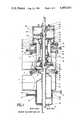
- FIG. 1a schematic longitudinal section of a doubleseat valve in the closed position (left part of the drawing) and the open position (right part of the drawing),
- FIG. 2a schematic longitudinal section through the double-seat valve shown in FIG. 1 in the intermediate position of the first closure member (right part of the drawing) and the intermediate position of the second closure member (left part of the drawing),
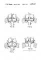
- FIG. 3aa schematic partial section through a modified double-seat valve in the closed position
- FIG. 3ba schematic partial section through the double-seat valve shown in FIG. 3a in the intermediate position of the first closure member
- FIG. 3ca schematic partial section through the double-seat valve shown in FIGS. 3a and 3b in the intermediate position of the second closure member
- FIG. 3da schematic partial section through the double-seat valve shown in FIGS. 3a to 3c in the open position
- FIG. 4aa schematic partial section through a modified double-seat valve in the closed position
- FIG. 4ba schematic partial section through the double-seat valve shown in FIG. 4a in the intermediate position of the first closure member
- FIG. 4ca schematic partial section through the double-seat valve shown in FIGS. 4a and 4b in the intermediate position of the second closure member
- FIG. 4da schematic partial section through the doubleseat valve shown in FIGS. 4a to 4c in the open position.
- the double seat valve shown in FIGS. 1 and 2comprises a valve housing 11 consisting of an upper housing member 11a having a conduit opening 1, a lower housing member 11b having a conduit opening 2, and a cover member 11c.
- the conduit openings 1 and 2are adapted for connection to conduits (not shown) which in operation are used for delivering fluid or a cleaning liquid, respectively.
- the upper housing member 11a and the lower housing member 11bbeing releasibly connected by a clamping member 52, communicate through a valve opening forming an axial valve seat 3a and a cylindrical valve seat 3b.
- a first closure memberforming a slide piston 8 and a second closure member 9 between an open position and a closed position.
- the first and second valve memberstogether realize in their closed positions a double seal between the space within the upper housing member 11a and the space within the lower housing member 11b.
- the slide piston 8is provided with a radial sealing ring 4 adapted to be in the closed position in sealing contact with the cylindrical valve seat 3b.
- the second closure member 9has an axial sealing ring 5 adapted to sealingly abut in the closed position with the axial valve seat 3a of the upper housing member 11a.
- the second closure member 9has a cylindrical piston wall 9a sealingly guided for axial displacement in an opening of the cover member 11c.
- the slide piston 8is rigidly connected to a coaxial rod 14 and a drive piston 17 having substantially the same outer diameter than the cylindrical valve seat 3b and being guided for axial displacement in a slide ring 13 in the lower housing member 11b.
- the rod 14is guided for axial displacement in a slide ring 12 disposed in a central opening of an auxiliary cylinder 34 rigidly mounted on an upper flange of the cover member 11c.
- the slide piston 8, the drive piston 17 and the rod 14form a rigid unit slidably guided near both ends thereof.
- a lakeage space 7in both the closed and the open positions thereof.
- Said leakage space 7is permanently connected to the outside by a drain channel 6 extending coaxially through the drive cylinder 17 and an opening in the lower wall of the lower housing member 11b.
- the rod 14there is provided an axial inlet channel 22 communicating via radial bores with the leakage space 7.
- inlet channel 22By introducing a cleaning fluid through inlet channel 22 it is possible to clean the leakage space 7 and the drain channel 6 in both the open and the closed positions of the first and second closure members 8 and 9.
- the rod 14is additionally guided in a slide ring 15 in the annular second closure member 9.
- first compression spring 18In the internal space surrounded by the cylindrical piston wall 9a of the second closure member 9 there are arranged a first compression spring 18 and a second compression spring 19.
- the first compression spring 18is supported at its end remote from the valve seats against an auxiliary drive cylinder 43 rigidly mounted within the auxiliary cylinder 34 for purposes to be described later.
- the first compression spring 18permanently urges the second closure member 9 into its closed position.
- the weaker second compression spring 19permanently acts against the second closure member 9 in order to hold together the lower and upper closure members 8 and 9.
- the prime mover for opening the valveis a pneumatic motor comprising a gas chamber 32 formed between the drive piston 17 and the bottom wall of the lower housing member 11b.
- compressed gasis introduced into the gas chamber 32 via the inlet opening 20. Since the gas pressure will be greater than the strength of the first compression spring 18, the slide piston 8 and the rod 14 both rigidly connected to the drive piston 17 begin to move upwardly against the force of the first compression spring 18.
- the second closure member 9is provided at its end facing the slide piston 8 with a recess 10 having a substantially cylindrical seat wall 10a coaxial to the cylindrical valve seat 3b and dimensioned to receive during opening movement the end portion of the slide piston 8 before the second closure member 9 opens.
- the first compression spring 18forces the two united closure members 8 and 9 downwardly until the axial sealing ring 5 of the second closure member 9 sealingly rests against the axial valve seat 3a so that the second closure member 9 comes to a rest in its closed position, whereas the slide piston 8 continues to be moved downward by the first compression spring 18 until there is reached the fully closed position shown in the left-hand half of FIG. 1.
- washing space 24between sealing rings 25, said washing space 24 having an inlet channel 26 and an outlet channel 27 for a cleaning fluid.
- the lower housing member 11bis provided with a washing space 28 disposed between sealing rings 29 and having an inlet channel 30 and an outlet channel 31 for cleaning fluid.
- annular groove 10bdisposed at the entrance end of the cylindrical seat wall 10a of the recess 10.
- the adjacent edge of the cylindrical valve seat 3bis slightly beveled and forms in the closed position of the second closure member 9 a sidewall for said annular groove 10b which is dimensioned to permit in an intermediate position of the radial sealing ring 4 opposite said annular groove 10b a flow of cleaning liquid along the cylindrical valve seat 3b and between the opposed circumferencial surfaces of the sealing ring 4 and the annular groove 10b.
- auxiliary drive meansidependent from the pneumatic motor adapted to move the drive piston 17.
- auxiliary piston 35having a radial sealing ring 36 being in permanent sealing contact with the internal circumferential surface of the auxiliary cylinder 34.
- the auxiliary piston 35separates an upper gas chamber 40 having an inlet opening 38 from a lower gas chamber 39 having an inlet opening 37.
- the annular auxiliary piston 33is sealingly guided for limited axial movement on the rod 14 which has an external projection 41 cooperating with an internal shoulder 42 of the auxiliary piston 35 for limiting the axial movement thereof.
- a second annular auxiliary piston 44guided for limited axial movement in the auxiliary drive cylinder 43.
- the annular auxiliary piston 44separates a lower gas chamber 46 connected via an annular channel 49 with an inlet opening 48 from an upper gas chamber 45 having an inlet opening 47.
- the internal circumferential wall of the auxiliary drive cylinder 43is provided with an abutment 50 for limiting the upward movement of the second auxiliary piston 44 which in addition cooperates at its inner margin with a projection 51 at the upper end of the cylindrical piston wall 9a of the second closure member 9.
- this projectionis a circlip 31 engaged in an annular groove of the cylindrical piston wall 9a.
- FIGS. 3a to 3dThe double seat valve shown in FIGS. 3a to 3d is closely similar in construction and operation to the valve shown in FIGS. 1 and 2, except that the second closure member 9 also has a radial sealing ring 3a which in the closed position is in sealing contact with a second cylindrical valve seat 3c having a diameter slightly larger than the first cylindrical valve seat 3b.
- a second annular groove 3d in the second cylindrical valve seat 3cat a predetermined distance above the area which in the closed position is in contact with the radial sealing ring 3a.
- FIG. 3ashows the modified double-seat valve in its closed position, whereas the intermediate position of the slide piston 8 is shown in FIG.
- FIG. 3bthe intermediate position of the second closure member 9 is shown in FIG. 3c and the open position of the valve is shown in FIG. 3d.
- the movement of the closure members between their closed position and their open position, the movement of the slide piston between its closed position and the intermediate position, and the movement of the second closure member between its closed position and its intermediate positionare effected in the same way explained in connection with FIGS. 1 and 2 by moving the drive piston 17 or the auxiliary piston 35 or the second auxiliary piston 44 by means of pressurized gas.
- the double-seat valve shown in FIGS. 4a to 4dis also closely similar in construction and operation to the valve shown in and described in connection with FIGS. 1 and 2, except that said slide piston 8 comprises at its end facing the second closure member 9 an axially protruding outer annular rim 8a having a substantially cylindrical inner wall 8b, whereas the second closure member 9 is provided with an annular recess 10 having a cylindrical inner wall 10c dimensioned to receive during opening movement the annular rim 8a of the slide piston 8.
- a radial sealing ring 16for sealing during opening movement against the opposed inner wall 10c or 8b, respectively, shortly before the second valve member 9 is lifted off its axial valve seat 3a.
- the annular groove 3dis disposed in the cylindrical valve seat 3b in order to enable in the position of the radial sealing ring 4 opposite said annular groove 3d a flow of cleaning liquid along the cylindrical valve seat 3b and between the radial sealing ring 4 and the opposed surfaces of the annular groove 3d into the leakage space 7.
- the movement of the clousre members between the closed and open positions or the closed and intermediate positions, respectivelyare effected in the same way as described in connection with FIGS. 1 and 2.
- FIG. 4ashows the modified double-seat valve in its closed position
- FIG. 4bshows the valve in the intermediate position of the slide piston 8
- 4cshows the intermediate position of the second closure member 9
- FIG. 4bthe valve in the open position.
Landscapes
- Engineering & Computer Science (AREA)
- General Engineering & Computer Science (AREA)
- Mechanical Engineering (AREA)
- Lift Valve (AREA)
Abstract
Description
Claims (11)
Priority Applications (1)
| Application Number | Priority Date | Filing Date | Title |
|---|---|---|---|
| US06/651,700US4605035A (en) | 1984-09-14 | 1984-09-14 | Double seat valve |
Applications Claiming Priority (1)
| Application Number | Priority Date | Filing Date | Title |
|---|---|---|---|
| US06/651,700US4605035A (en) | 1984-09-14 | 1984-09-14 | Double seat valve |
Publications (1)
| Publication Number | Publication Date |
|---|---|
| US4605035Atrue US4605035A (en) | 1986-08-12 |
Family
ID=24613868
Family Applications (1)
| Application Number | Title | Priority Date | Filing Date |
|---|---|---|---|
| US06/651,700Expired - LifetimeUS4605035A (en) | 1984-09-14 | 1984-09-14 | Double seat valve |
Country Status (1)
| Country | Link |
|---|---|
| US (1) | US4605035A (en) |
Cited By (31)
| Publication number | Priority date | Publication date | Assignee | Title |
|---|---|---|---|---|
| US4757834A (en)* | 1985-06-11 | 1988-07-19 | Otto Tuchenhagen Gmbh & Co. Kg | Method and apparatus for the realization of a leakage-free switching double seat valve adapted for cleaning seat surfaces |
| WO1989006763A1 (en)* | 1988-01-20 | 1989-07-27 | Mieth Hans Otto | Process and device for protection and support of a seal in a valve arrangement |
| US5575305A (en)* | 1991-06-07 | 1996-11-19 | Otto Tuchenhagen Gmbh & Co. Kg | Procedure for cleaning a double seat valve and valve arrangement for implementing the process |
| US5645102A (en)* | 1993-09-21 | 1997-07-08 | Apv Rosista Gmbh | Leak resistant, switching, double valve system |
| US5649563A (en)* | 1995-04-27 | 1997-07-22 | Surpass Industry Co., Ltd. | Fluid coupling |
| WO1997039266A1 (en)* | 1996-04-13 | 1997-10-23 | Tuchenhagen Gmbh | Double-seated valve with a controlled leakage space |
| US5699825A (en)* | 1995-11-14 | 1997-12-23 | United Dominion Industries, Inc. | Double seat flow control valve |
| US5771926A (en)* | 1995-11-03 | 1998-06-30 | Medal; George L. | Double seat value with switch monitoring design |
| US5806554A (en)* | 1992-02-08 | 1998-09-15 | Otto Tuchenhagen Gmbh & Co. Kg | Double seat valve |
| US5904173A (en)* | 1996-07-15 | 1999-05-18 | Toyo Stainless Steel Industries, Co., Ltd. | Double sealed valve |
| DE19750300A1 (en)* | 1997-11-13 | 1999-06-02 | Alfa Laval Lkm A S | Double seat valve |
| US6009896A (en)* | 1996-10-07 | 2000-01-04 | Hovap International (Holland) B.V. | Shut-off valve |
| US6014983A (en)* | 1995-12-27 | 2000-01-18 | Alfa Laval Lkm A/S | Stop valve |
| US6047730A (en)* | 1995-12-20 | 2000-04-11 | Tuchenhagen Gmbh | Device for the drive system for double seat valves |
| US6056003A (en)* | 1997-05-28 | 2000-05-02 | Tetra Laval Holdings & Finance S.A. | Double-seated valve |
| US6098645A (en)* | 1997-05-16 | 2000-08-08 | Apv Rosista Gmbh | Leak resistant, switching, double valve system |
| WO2001002763A1 (en)* | 1999-07-02 | 2001-01-11 | Alfa Laval Lkm A/S | Double sealing valve |
| US6178986B1 (en)* | 1997-03-18 | 2001-01-30 | Tuchenhagen Gmbh | Double seat valve with cleanable seats |
| US6349742B1 (en)* | 1997-05-30 | 2002-02-26 | Alfa Laval Lkm A/S | Dual-seat valve able to switch in a leak-free manner |
| US20040206579A1 (en)* | 1998-02-26 | 2004-10-21 | Baranda Pedro S. | Tension member for an elevator |
| US20050247343A1 (en)* | 2002-08-14 | 2005-11-10 | Tuchenhagen Gmbh A German Corporation | Device for actuating double seat valves |
| US20070215830A1 (en)* | 2006-03-15 | 2007-09-20 | United Dominion Industries, Inc. | Method and apparatus for providing cleanability to a valve |
| US20090044874A1 (en)* | 2005-11-12 | 2009-02-19 | Jens Burmester | Double Seat Valve |
| US20100072411A1 (en)* | 2008-09-19 | 2010-03-25 | Larry Norton | Double seat valve apparatus and method |
| US20100102259A1 (en)* | 2008-10-15 | 2010-04-29 | Karl Dungs Gmbh & Co. Kg | Tubular valve device |
| US20100276004A1 (en)* | 2007-10-19 | 2010-11-04 | Alfa Laval Kolding A/S | Method for Operating a Valve |
| US20120112112A1 (en)* | 2010-11-04 | 2012-05-10 | Fisher Controls International Llc | Biasing Device for Use With Actuators of Fluid Valves |
| US20160123475A1 (en)* | 2016-01-12 | 2016-05-05 | Engip, LLC | Dual Seat Valve |
| US20190353255A1 (en)* | 2018-05-15 | 2019-11-21 | Evoguard Gmbh | Valve combination |
| JP2020528125A (en)* | 2017-07-25 | 2020-09-17 | ゲーエーアー トゥーヘンハーゲン ゲーエムベーハー | Double seat valve with diaphragm |
| US20240060571A1 (en)* | 2019-10-18 | 2024-02-22 | Gea Farm Technologies Gmbh | Safety valve |
Citations (9)
| Publication number | Priority date | Publication date | Assignee | Title |
|---|---|---|---|---|
| DE2456675A1 (en)* | 1974-11-30 | 1976-06-10 | Rosista Gmbh | Transport of products in pipe lines - has pair of valve bodies adjusting slit diameter of pipeline flow sections |
| DE2751734A1 (en)* | 1977-11-19 | 1979-06-28 | Holstein & Kappert Maschf | Double seat valve with leak indicator - has two adjusting mechanisms for first plate and one for second |
| DE3005329A1 (en)* | 1980-02-13 | 1981-08-20 | Leonhard Schleicher Südmo-Armaturenfabrik GmbH, 7081 Riesbürg | Double acting valve for fluid process - has coaxial telescopic valve stem with single drive and independent operation |
| US4304251A (en)* | 1977-11-19 | 1981-12-08 | Schaedel Hermann | Double seat valve with leak control |
| DE3108778A1 (en)* | 1980-07-22 | 1982-06-03 | Otto Tuchenhagen GmbH & Co KG, 2059 Büchen | "DEVICE FOR SIMULTANEOUS CLEANING OF BOTH SEATS OF AT LEAST ONE-SIDED, DOUBLE-SEAT VALVE IN PROTECTED PRODUCT AND METHOD FOR CLEANING" |
| US4360039A (en)* | 1979-11-20 | 1982-11-23 | Jeppsson Hakan E O | Valves |
| US4373545A (en)* | 1981-01-26 | 1983-02-15 | Cherry-Burrell Corporation | Double block and vent valve |
| US4436106A (en)* | 1977-01-29 | 1984-03-13 | Otto Tuchenhagen Gmbh & Co. Kg | Pipeline switch with leakage control and cleanable leakage cavity |
| US4460014A (en)* | 1980-04-24 | 1984-07-17 | Alfa-Laval Ab | Non-mixing valve |
- 1984
- 1984-09-14USUS06/651,700patent/US4605035A/ennot_activeExpired - Lifetime
Patent Citations (9)
| Publication number | Priority date | Publication date | Assignee | Title |
|---|---|---|---|---|
| DE2456675A1 (en)* | 1974-11-30 | 1976-06-10 | Rosista Gmbh | Transport of products in pipe lines - has pair of valve bodies adjusting slit diameter of pipeline flow sections |
| US4436106A (en)* | 1977-01-29 | 1984-03-13 | Otto Tuchenhagen Gmbh & Co. Kg | Pipeline switch with leakage control and cleanable leakage cavity |
| DE2751734A1 (en)* | 1977-11-19 | 1979-06-28 | Holstein & Kappert Maschf | Double seat valve with leak indicator - has two adjusting mechanisms for first plate and one for second |
| US4304251A (en)* | 1977-11-19 | 1981-12-08 | Schaedel Hermann | Double seat valve with leak control |
| US4360039A (en)* | 1979-11-20 | 1982-11-23 | Jeppsson Hakan E O | Valves |
| DE3005329A1 (en)* | 1980-02-13 | 1981-08-20 | Leonhard Schleicher Südmo-Armaturenfabrik GmbH, 7081 Riesbürg | Double acting valve for fluid process - has coaxial telescopic valve stem with single drive and independent operation |
| US4460014A (en)* | 1980-04-24 | 1984-07-17 | Alfa-Laval Ab | Non-mixing valve |
| DE3108778A1 (en)* | 1980-07-22 | 1982-06-03 | Otto Tuchenhagen GmbH & Co KG, 2059 Büchen | "DEVICE FOR SIMULTANEOUS CLEANING OF BOTH SEATS OF AT LEAST ONE-SIDED, DOUBLE-SEAT VALVE IN PROTECTED PRODUCT AND METHOD FOR CLEANING" |
| US4373545A (en)* | 1981-01-26 | 1983-02-15 | Cherry-Burrell Corporation | Double block and vent valve |
Cited By (48)
| Publication number | Priority date | Publication date | Assignee | Title |
|---|---|---|---|---|
| US4757834A (en)* | 1985-06-11 | 1988-07-19 | Otto Tuchenhagen Gmbh & Co. Kg | Method and apparatus for the realization of a leakage-free switching double seat valve adapted for cleaning seat surfaces |
| WO1989006763A1 (en)* | 1988-01-20 | 1989-07-27 | Mieth Hans Otto | Process and device for protection and support of a seal in a valve arrangement |
| US5048555A (en)* | 1988-01-20 | 1991-09-17 | Mieth Hans Otto | Process and apparatus for protecting and supporting a seal of a valve |
| EP0337519A3 (en)* | 1988-01-20 | 1991-09-18 | Mieth, Hans Otto, Dipl.-Ing. | Method and device for the protection and the support of a valve gasket |
| US5575305A (en)* | 1991-06-07 | 1996-11-19 | Otto Tuchenhagen Gmbh & Co. Kg | Procedure for cleaning a double seat valve and valve arrangement for implementing the process |
| US5806554A (en)* | 1992-02-08 | 1998-09-15 | Otto Tuchenhagen Gmbh & Co. Kg | Double seat valve |
| US5645102A (en)* | 1993-09-21 | 1997-07-08 | Apv Rosista Gmbh | Leak resistant, switching, double valve system |
| JP3272165B2 (en) | 1993-09-21 | 2002-04-08 | アペーフアオ・ロジスタ・ゲゼルシヤフト・ミツト・ベシユレンクテル・ハフツング | Leakless switching double valve system |
| US5649563A (en)* | 1995-04-27 | 1997-07-22 | Surpass Industry Co., Ltd. | Fluid coupling |
| US5771926A (en)* | 1995-11-03 | 1998-06-30 | Medal; George L. | Double seat value with switch monitoring design |
| US5699825A (en)* | 1995-11-14 | 1997-12-23 | United Dominion Industries, Inc. | Double seat flow control valve |
| US6047730A (en)* | 1995-12-20 | 2000-04-11 | Tuchenhagen Gmbh | Device for the drive system for double seat valves |
| US6014983A (en)* | 1995-12-27 | 2000-01-18 | Alfa Laval Lkm A/S | Stop valve |
| WO1997039266A1 (en)* | 1996-04-13 | 1997-10-23 | Tuchenhagen Gmbh | Double-seated valve with a controlled leakage space |
| US5904173A (en)* | 1996-07-15 | 1999-05-18 | Toyo Stainless Steel Industries, Co., Ltd. | Double sealed valve |
| US6009896A (en)* | 1996-10-07 | 2000-01-04 | Hovap International (Holland) B.V. | Shut-off valve |
| US6178986B1 (en)* | 1997-03-18 | 2001-01-30 | Tuchenhagen Gmbh | Double seat valve with cleanable seats |
| US6098645A (en)* | 1997-05-16 | 2000-08-08 | Apv Rosista Gmbh | Leak resistant, switching, double valve system |
| US6056003A (en)* | 1997-05-28 | 2000-05-02 | Tetra Laval Holdings & Finance S.A. | Double-seated valve |
| US6349742B1 (en)* | 1997-05-30 | 2002-02-26 | Alfa Laval Lkm A/S | Dual-seat valve able to switch in a leak-free manner |
| DE19750300A1 (en)* | 1997-11-13 | 1999-06-02 | Alfa Laval Lkm A S | Double seat valve |
| US6186163B1 (en)* | 1997-11-13 | 2001-02-13 | Alfa Laval Lkm Aps | Double seat valve |
| US20040206579A1 (en)* | 1998-02-26 | 2004-10-21 | Baranda Pedro S. | Tension member for an elevator |
| JP2003503668A (en)* | 1999-07-02 | 2003-01-28 | アルファ ラァヴァル エルケーエム アー/エス | Double sealed valve |
| WO2001002762A1 (en)* | 1999-07-02 | 2001-01-11 | Alfa Laval Lkm A/S | Double sealing valve |
| US6676047B1 (en) | 1999-07-02 | 2004-01-13 | Alfa Laval A/S | Double sealing valve |
| WO2001002763A1 (en)* | 1999-07-02 | 2001-01-11 | Alfa Laval Lkm A/S | Double sealing valve |
| US20050247343A1 (en)* | 2002-08-14 | 2005-11-10 | Tuchenhagen Gmbh A German Corporation | Device for actuating double seat valves |
| US7198058B2 (en)* | 2002-08-14 | 2007-04-03 | Tuchenhagen Gmbh | Device for actuating double seat valves |
| US20090044874A1 (en)* | 2005-11-12 | 2009-02-19 | Jens Burmester | Double Seat Valve |
| US7845368B2 (en)* | 2005-11-12 | 2010-12-07 | Tuchenhagen Gmbh | Double seat valve |
| US20070215830A1 (en)* | 2006-03-15 | 2007-09-20 | United Dominion Industries, Inc. | Method and apparatus for providing cleanability to a valve |
| US8910650B2 (en)* | 2007-10-19 | 2014-12-16 | Alfa Laval Kolding A/S | Method for operating a valve |
| US20100276004A1 (en)* | 2007-10-19 | 2010-11-04 | Alfa Laval Kolding A/S | Method for Operating a Valve |
| US20100072411A1 (en)* | 2008-09-19 | 2010-03-25 | Larry Norton | Double seat valve apparatus and method |
| US8327881B2 (en) | 2008-09-19 | 2012-12-11 | Spx Corporation | Double seat valve apparatus |
| US8286937B2 (en)* | 2008-10-15 | 2012-10-16 | Karl Dungs Gmbh & Co. Kg | Tubular valve device |
| US20100102259A1 (en)* | 2008-10-15 | 2010-04-29 | Karl Dungs Gmbh & Co. Kg | Tubular valve device |
| US20120112112A1 (en)* | 2010-11-04 | 2012-05-10 | Fisher Controls International Llc | Biasing Device for Use With Actuators of Fluid Valves |
| US8579249B2 (en)* | 2010-11-04 | 2013-11-12 | Fisher Controls International Llc | Biasing device for use with actuators of fluid valves |
| US20160123475A1 (en)* | 2016-01-12 | 2016-05-05 | Engip, LLC | Dual Seat Valve |
| US10113650B2 (en)* | 2016-01-12 | 2018-10-30 | Engip, LLC | Dual seat valve |
| US10655737B2 (en) | 2016-01-12 | 2020-05-19 | Engip Llc | Dual seat valve |
| JP2020528125A (en)* | 2017-07-25 | 2020-09-17 | ゲーエーアー トゥーヘンハーゲン ゲーエムベーハー | Double seat valve with diaphragm |
| JP7072048B2 (en) | 2017-07-25 | 2022-05-19 | ゲーエーアー トゥーヘンハーゲン ゲーエムベーハー | Double seat valve with diaphragm |
| US20190353255A1 (en)* | 2018-05-15 | 2019-11-21 | Evoguard Gmbh | Valve combination |
| US20240060571A1 (en)* | 2019-10-18 | 2024-02-22 | Gea Farm Technologies Gmbh | Safety valve |
| US12085179B2 (en)* | 2019-10-18 | 2024-09-10 | Gea Farm Technologies Gmbh | Safety valve |
Similar Documents
| Publication | Publication Date | Title |
|---|---|---|
| US4605035A (en) | Double seat valve | |
| EP0174384A1 (en) | Double seat valve | |
| US4460014A (en) | Non-mixing valve | |
| EP0140432B1 (en) | Shut-off valve | |
| US4960188A (en) | Single-tube vibration damper of variable damping force | |
| US4360039A (en) | Valves | |
| US6230736B1 (en) | Valve, particularly double-seat valve | |
| US6186163B1 (en) | Double seat valve | |
| US4728084A (en) | Adjustable-length gas spring | |
| US6349742B1 (en) | Dual-seat valve able to switch in a leak-free manner | |
| US5609343A (en) | Sealing rings for spool valves | |
| NL8006542A (en) | VALVE WITH LEAKAGE PROTECTION IN PIPELINE SYSTEMS. | |
| US4219190A (en) | Gas spring | |
| US8430110B2 (en) | Double-seat valve having a seat-cleaning function, and method for cleaning said double-seat valve having a seat-cleaning function | |
| GB2186951A (en) | Rotary valve | |
| US4037753A (en) | Container closure, especially for mixing containers | |
| JPS6219615B2 (en) | ||
| US3987705A (en) | Device for opening and closing a mold in a molding machine | |
| NZ274149A (en) | Leak free sealing system for double seat valve with radial sealing means inside cylindrical valve seat surface | |
| JPS6216545Y2 (en) | ||
| US4757835A (en) | Change-over valve for hydraulic walking mine-roof supports | |
| US4516470A (en) | Unbalanced hydraulic amplifier valve assembly | |
| US3841204A (en) | Combination end cover seal arrangement | |
| US4787206A (en) | Hydraulic pressure transducer | |
| GB2099531A (en) | Apparatus for conveying a pressure medium from a stationary housing to a rotatable shaft |
Legal Events
| Date | Code | Title | Description |
|---|---|---|---|
| AS | Assignment | Owner name:LAVRIDS KNUDSEN MASKINFABRIK A/S, DK-6000 KOLDING, Free format text:ASSIGNMENT OF ASSIGNORS INTEREST.;ASSIGNORS:RASMUSSEN, ERIK;LUNDOUIST, GUNNAR;LADING, STIG;REEL/FRAME:004368/0418 Effective date:19850123 | |
| STCF | Information on status: patent grant | Free format text:PATENTED CASE | |
| FEPP | Fee payment procedure | Free format text:PAYOR NUMBER ASSIGNED (ORIGINAL EVENT CODE: ASPN); ENTITY STATUS OF PATENT OWNER: LARGE ENTITY | |
| FPAY | Fee payment | Year of fee payment:4 | |
| FPAY | Fee payment | Year of fee payment:8 | |
| FEPP | Fee payment procedure | Free format text:PAYOR NUMBER ASSIGNED (ORIGINAL EVENT CODE: ASPN); ENTITY STATUS OF PATENT OWNER: LARGE ENTITY Free format text:PAYER NUMBER DE-ASSIGNED (ORIGINAL EVENT CODE: RMPN); ENTITY STATUS OF PATENT OWNER: LARGE ENTITY | |
| FPAY | Fee payment | Year of fee payment:12 | |
| AS | Assignment | Owner name:ALFA LAVAL LKM A/S, DENMARK Free format text:CHANGE OF NAME;ASSIGNOR:LAVRIDS KNUDSEN MASKINEFABRIK A/S;REEL/FRAME:009833/0476 Effective date:19980317 |