US4604538A - Air cooling for diode-rectified alternating current generators - Google Patents
Air cooling for diode-rectified alternating current generatorsDownload PDFInfo
- Publication number
- US4604538A US4604538AUS06/703,123US70312385AUS4604538AUS 4604538 AUS4604538 AUS 4604538AUS 70312385 AUS70312385 AUS 70312385AUS 4604538 AUS4604538 AUS 4604538A
- Authority
- US
- United States
- Prior art keywords
- fan
- end frame
- air
- stator winding
- openings formed
- Prior art date
- Legal status (The legal status is an assumption and is not a legal conclusion. Google has not performed a legal analysis and makes no representation as to the accuracy of the status listed.)
- Expired - Lifetime
Links
- 238000001816coolingMethods0.000titleclaimsabstractdescription69
- 238000004804windingMethods0.000claimsabstractdescription60
- 229910052751metalInorganic materials0.000claimsdescription6
- 239000002184metalSubstances0.000claimsdescription6
- 239000007769metal materialSubstances0.000claims2
- 239000012212insulatorSubstances0.000description44
- RYGMFSIKBFXOCR-UHFFFAOYSA-NCopperChemical compound[Cu]RYGMFSIKBFXOCR-UHFFFAOYSA-N0.000description16
- 229910052802copperInorganic materials0.000description15
- 239000010949copperSubstances0.000description15
- 239000000463materialSubstances0.000description14
- 238000002788crimpingMethods0.000description10
- 239000011810insulating materialSubstances0.000description10
- 229920002379silicone rubberPolymers0.000description10
- 239000004945silicone rubberSubstances0.000description10
- 239000004033plasticSubstances0.000description8
- 229910052782aluminiumInorganic materials0.000description7
- XAGFODPZIPBFFR-UHFFFAOYSA-NaluminiumChemical compound[Al]XAGFODPZIPBFFR-UHFFFAOYSA-N0.000description7
- 239000004519greaseSubstances0.000description7
- 239000004065semiconductorSubstances0.000description7
- 125000006850spacer groupChemical group0.000description6
- 238000000576coating methodMethods0.000description5
- 239000004020conductorSubstances0.000description5
- 239000011521glassSubstances0.000description5
- 229910000831SteelInorganic materials0.000description4
- 239000011248coating agentSubstances0.000description4
- 238000010586diagramMethods0.000description4
- 210000005069earsAnatomy0.000description4
- 239000003365glass fiberSubstances0.000description4
- 239000011253protective coatingSubstances0.000description4
- 239000010959steelSubstances0.000description4
- 239000002966varnishSubstances0.000description4
- 239000004677NylonSubstances0.000description3
- 230000000712assemblyEffects0.000description3
- 238000000429assemblyMethods0.000description3
- 229920001778nylonPolymers0.000description3
- 229920003223poly(pyromellitimide-1,4-diphenyl ether)Polymers0.000description3
- PXHVJJICTQNCMI-UHFFFAOYSA-NNickelChemical compound[Ni]PXHVJJICTQNCMI-UHFFFAOYSA-N0.000description2
- XUIMIQQOPSSXEZ-UHFFFAOYSA-NSiliconChemical compound[Si]XUIMIQQOPSSXEZ-UHFFFAOYSA-N0.000description2
- XLOMVQKBTHCTTD-UHFFFAOYSA-NZinc monoxideChemical compound[Zn]=OXLOMVQKBTHCTTD-UHFFFAOYSA-N0.000description2
- 239000003990capacitorSubstances0.000description2
- 239000000696magnetic materialSubstances0.000description2
- 239000000615nonconductorSubstances0.000description2
- 229910052710siliconInorganic materials0.000description2
- 239000010703siliconSubstances0.000description2
- 229910000679solderInorganic materials0.000description2
- 229910000639Spring steelInorganic materials0.000description1
- 239000000853adhesiveSubstances0.000description1
- 238000004026adhesive bondingMethods0.000description1
- 230000001070adhesive effectEffects0.000description1
- 230000002411adverseEffects0.000description1
- AZDRQVAHHNSJOQ-UHFFFAOYSA-NalumaneChemical group[AlH3]AZDRQVAHHNSJOQ-UHFFFAOYSA-N0.000description1
- 238000010073coating (rubber)Methods0.000description1
- 229910003460diamondInorganic materials0.000description1
- 239000010432diamondSubstances0.000description1
- 239000013536elastomeric materialSubstances0.000description1
- 238000007689inspectionMethods0.000description1
- 238000003475laminationMethods0.000description1
- 239000002991molded plasticSubstances0.000description1
- 238000010137moulding (plastic)Methods0.000description1
- 229910052759nickelInorganic materials0.000description1
- 239000003973paintSubstances0.000description1
- 238000002161passivationMethods0.000description1
- 150000003839saltsChemical class0.000description1
- 239000007921spraySubstances0.000description1
- 238000003466weldingMethods0.000description1
- 239000011787zinc oxideSubstances0.000description1
Images


Classifications
- H—ELECTRICITY
- H02—GENERATION; CONVERSION OR DISTRIBUTION OF ELECTRIC POWER
- H02K—DYNAMO-ELECTRIC MACHINES
- H02K9/00—Arrangements for cooling or ventilating
- H02K9/02—Arrangements for cooling or ventilating by ambient air flowing through the machine
- H02K9/04—Arrangements for cooling or ventilating by ambient air flowing through the machine having means for generating a flow of cooling medium
- H02K9/06—Arrangements for cooling or ventilating by ambient air flowing through the machine having means for generating a flow of cooling medium with fans or impellers driven by the machine shaft
- H—ELECTRICITY
- H02—GENERATION; CONVERSION OR DISTRIBUTION OF ELECTRIC POWER
- H02K—DYNAMO-ELECTRIC MACHINES
- H02K11/00—Structural association of dynamo-electric machines with electric components or with devices for shielding, monitoring or protection
- H02K11/04—Structural association of dynamo-electric machines with electric components or with devices for shielding, monitoring or protection for rectification
- H02K11/049—Rectifiers associated with stationary parts, e.g. stator cores
- H02K11/05—Rectifiers associated with casings, enclosures or brackets
Definitions
- This inventionrelates to air cooling of a diode-rectified alternating current generator and more particularly to the air cooling of diode-rectified alternating current generators that are used on motor vehicles to supply the electrical loads on the vehicle.
- the air cooling flow paths for air impelled by the two fansis arranged such that air cooling flow paths, in addition to a flow path between the openings in the end frames of the generator, are provided.
- the internal fan of the generator of this inventioncauses a flow of cooling air past the bridge rectifier of the generator and past one end of the stator winding.
- This cooling pathis between air inlet openings formed in the end wall of the slip ring end frame of the generator and air outlet openings formed in a circumferentially extending portion of the slip ring end frame.
- the external fanis located adjacent the drive end frame of the generator and impels cooling air past the other end of the stator winding by a path that is between air inlet grooves formed in the drive end frame of the generator and air outlet openings formed in an end wall of the drive end frame.
- the external fanalso causes a flow of cooling air between air inlet openings in the slip ring end frame and the air outlet openings in the drive end frame.
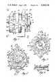
- FIG. 1is an exterior side view of a diode-rectified alternating current generator
- FIG. 2is an end view of the alternator illustrated in FIG. 1 looking in the direction of arrows 2--2 of FIG. 1;
- FIG. 3is an end view of the alternator illustrated in FIG. 1 looking in the direction of arrows 3--3 of FIG. 1;
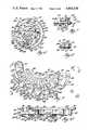
- FIG. 4is a sectional view taken along lines 4--4 of FIG. 2;
- FIG. 5is a sectional view of the alternator looking in the direction of arrows 5--5 of FIG. 2;
- FIG. 6is an internal view partly in section and with parts broken away of the slip ring end frame of the alternator illustrated in FIG. 5 looking in the direction of arrows 6--6 of FIG. 5;
- FIG. 7is a sectional view taken along lines 7--7 of FIG. 6;
- FIG. 8is a sectional view taken along lines 8--8 of FIG. 6;
- FIG. 9is a plan view of a bridge rectifier looking in the direction of arrows 9--9 of FIG. 5;
- FIG. 10is an end view of the bridge rectifier illustrated in FIG. 9 looking in the direction of arrows 10--10 of FIG. 9;
- FIG. 11is another end view of the bridge rectifier illustrated in FIG. 9 looking in the direction of arrows 11--11 of FIG. 9;
- FIG. 12is another view of the bridge rectifier illustrated in FIG. 9 looking in the direction of arrows 12--12 of FIG. 9;
- FIG. 13is a schematic circuit diagram of the bridge rectifier illustrated in FIG. 9;
- FIG. 14is a plan view of an insulator utilized in the bridge rectifier of FIG. 9;
- FIG. 15is a plan view of a heat sink that is utilized in the bridge rectifier of FIG. 9;
- FIG. 16is a view of a rotor core and field coil assembly looking in the direction of arrows 16--16 of FIG. 5;
- FIG. 17is an end view of a fan that forms a part of the rotor assembly of the alternator of this invention looking in the direction of arrows 17--17 of FIG. 5;
- FIG. 18is a sectional view taken along lines 18--18 of FIG. 17;
- FIGS. 19 and 20are respectively plan and side views of a diode assembly utilized in the bridge rectifier of FIG. 9;
- FIG. 21is a plan view of a modified bridge rectifier
- FIG. 22is an end view of the bridge rectifier illustrated in FIG. 21 looking in the direction of arrows 22--22 of FIG. 21;
- FIG. 23is a view of the bridge rectifier illustrated in FIG. 21 looking in the direction of arrows 23--23 of FIG. 21;
- FIG. 24is a sectional view taken along lines 24--24 of FIG. 21.
- FIG. 25is a sectional view illustrating how a cover member is attached to the modified bridge rectifier shown in FIG. 21.
- the diode-rectified alternating current generator of this inventioncomprises a drive end frame 30 and a slip ring end frame 32 both of which are formed of die cast aluminum material.
- the alternatorhas a stator assembly generally designated by reference numeral 34 that is comprised of a stator core 36 formed of a plurality of steel stator laminations which are welded together and which have slots that contain a three phase Delta-connected stator winding 38.
- the laminated core 36is clamped between inner end surfaces of the end frames 30 and 32 which are secured together by through bolts 40.
- the bolts 40extend through openings in end frame 32 and are threaded into threaded openings formed in the end frame 30, as illustrated in FIG. 4.
- the slip ring end frame 32has eight air passages, each designated by reference numeral 41.
- the end frame 32has four rectangular inlet air passages 42 and air inlet passages 44, 46 and 48.
- the end frame 32further has three openings or slots 50, which are defined by axially extending walls 51.
- the slots 50are aligned with additional slots or passages defined by ribs 50A (FIG. 6) that extend axially of walls 51.
- the end frame 32carries a cover member 53 that is formed of plastic material and which is secured to end frame 32 by rivets.
- the cover 53has four recesses or slots 53A which form inlet air passages communicating with the passages or slots defined by ribs 50A.
- the cover 53is not secured to end frame 32 until after the end leads of stator winding 38 have been connected to connectors of a bridge rectifier, to be described hereinafter.
- internal portions of end frame 32 that are eventually covered by cover 53are accessible from the outside of end frame 32 to make the electrical connections between stator winding 38 and connectors of the bridge rectifier before the cover is attached to the end frame.
- the drive end frame 30has three air outlet passages, each designated as 30A.
- the drive end frame 30also has a pair of arcuately extending diametrically opposed air inlet passages 30B that are formed by grooves or slots formed in end frame 30. The surfaces of these grooves or slots are spaced from an end of stator core 36 and these slots extend circumferentially for about 65°.
- the end frame 30has another air inlet passage 30C which is formed by an arcuately extending groove or slot formed in end frame 30, the surface of which is spaced from an end of core 36. This slot extends circumferentially for about 20°.
- the air inlet passages 30B and 30Care aligned with portions of stator winding 38 located to the right of stator core 36, as viewed in FIG. 5.
- the alternatorhas a rotor assembly which is generally designated by reference numeral 54.
- This rotor assemblycomprises a shaft 56 which is journaled for rotation in ball bearings 58 and 59.
- the shaft 56has helix-diamond knurled portions 56A and 56B and a straight knurled portion 56C.
- the rotor 54has a pair of segments or pole members 60 and 62 which are formed of a magnetic material such as steel and which respectively have axially extending pole teeth 60A and 62A.
- the pole teeth of the two segmentsare interleaved, that is the pole teeth of one segment are located in the gaps between the pole teeth of the other segment.
- the inner surfaces of the pole teethare engaged by an aluminum ring 64.
- the segments 60 and 62have central openings that receive the shaft 56 and the segments are secured to the shaft 56 by circular staking portions of the segments into the knurled portions of the shaft as indicated by reference numerals 66 and 68.
- the rotor 54has a core and field coil assembly generally designated by reference numeral 69 which is illustrated in FIGS. 5 and 16.
- This assemblyincludes a cylindrical core member 70 which is formed of a magnetic material such as steel and which has a central bore that receives shaft 56.
- the core 70is secured to shaft 56 by circular staking portion 71 thereof into engagement with knurled portion 56B.
- the core member 70(FIG. 16) has eight axially extending circumferentially spaced slots 70A formed at the exterior thereof which extend the entire length of the core member 70.
- the slots 70Areceive axially extending circumferentially spaced ribs 72 of a spool 74 that is formed of electrical insulating material.
- the ribs 72extend between and are joined to end flanges 74A and 74B of spool 74.
- a field coil 76formed of a number of turns of insulated copper wire, is wound in the area between flanges 74A and 74B.
- the inner turns of the field coil 76directly engage the outer surfaces of ribs 72 and also directly engage outer arcuate surfaces 70B of the metallic core 70 located between ribs 72.
- the outer surface of the core 70is coated with a paint that forms a coating of electrical insulating material.
- the rotor 54has a cooling fan (FIG. 17) which is generally designated by reference numeral 78.
- the cooling fan 78is formed of plastic material and may be, for example, a one-piece plastic molding formed of nylon.
- the fan 78has a pair of axially spaced annular portions 78A and 78B and an annular portion 78C all of which are joined by axially extending radially curved fan blades 78D.
- the fan 78has a hub portion 78E which is connected to portion 78C by spokes 78F.
- the portion 78C of the fan 78has four circumferentially spaced holes 78J which respectively receive the ends of four circumferentially spaced posts 74C which are integral parts of the spool 74 and which extend axially from the annular flange 74B of the spool 74.
- the posts 74Chave surfaces 74D which engage one surface of fan portion 78C and have end portions which extend through the openings in the portion 78C of the fan 78. These end portions are headed or wedged over against an inner surface of the portion 78C as indicated by reference designation 74E by ultrasonic welding apparatus. It can be seen from the foregoing that the posts 74C serve to axially retain the fan against pole member 62.
- the posts 74Cextend through the gaps located between the pole teeth 62A of the segment 62.
- the rotor assembly 54has a slip ring assembly generally designated by reference numeral 80.
- This slip ring assemblycomprises a bored annular insulator 82 which is secured to the shaft 56 by forcing the insulator 82 over the straight knurled portion 56C.
- the insulator 82carries annular copper slip rings 84 and 86.
- the slip ringsare molded to the insulator 82 and each slip ring has an integral connector 84A and 86A, the ends of which are positioned respectively in metallic clips 88 and 90.
- the metallic clipsalso receive the end leads 76A and 76B of the field coil 76.
- the metallic clips 88 and 90are crimped to the conductors of the slip ring and the end leads of the field coil and are then welded thereto.
- the end leads 76A and 76Bare fitted into conductor retaining lugs 78K formed integral with the fan 78.
- the end leads 76A and 76Bare wound around posts 74F and 74G of spool 74 and extend respectively through holes 78L and 78M formed in axially extending cylindrical portions of fan 78.
- the hub portion 78E of fan 78is press-fitted to the shaft 56 and the fan is moved into engagement with pole member 62.
- the ends of the posts 74Cpass through the openings 78J in the fan and the ends of these posts are then headed over, as has been explained.
- the slip ring assembly 80is assembled to the shaft it is moved into engagement with the end of fan hub portion 78E and the fan lug 78H moves into a radially extending slot (not illustrated) formed in slip ring insulator 82.
- the slots 78G in the fan hub 78Ereceive the slip ring connectors 84A and 86A.
- the rotorAfter the rotor has been assembled, as has been described, it is dipped in varnish to impregnate the rotor in a manner well known to those skilled in the art.
- the varnishdue to wicking, flows to some extent between portions of the fan 78 and segment 62 and when the varnish has dried it bonds the fan to the segment.
- the fan 78is nonrotatably secured to shaft 56 by the just described varnish bonding, by the lug 78H which fits in the slot in the insulator 82, by the press-fit of the fan hub 78E with shaft 56 and to some extent by posts 74C that connect the field coil spool and fan.
- the fan 78has a circumferentially extending slot or gap 78P located between fan portions 78A and 78C. When the fan is assembled to the rotor this gap 78P is outboard of the unbroken portion of rotor pole member 62 and is aligned with the gaps between the pole teeth 62A. The gap 78P permits some axial flow of cooling air therethrough in a manner that is more fully described hereinafter.
- the fan 78cooperates with a fan baffle 79 which is formed of a plastic material such as glass filled nylon.
- the bafflehas an annular portion 79A and has an annular flange 79B defining a central circular opening 79C.
- the bafflehas another annular flange 79D.
- the baffle 79is secured to end frame 32 by a plurality of groups of resilient integral teeth 79E that are press-fitted into a plurality of holes 32A formed in end frame 32.
- the shaft 56carries a steel cooling fan designated by reference numeral 92 which has a plurality of fan blades 92A and also carries a drive pulley designated by reference numeral 94.
- the pulley and fanare secured to the shaft 56 by a nut 96 threaded onto a threaded end of shaft 56.
- End frame 32contains a bridge rectifier assembly which is generally designated by reference numeral 100 and which is illustrated in detail in FIGS. 9, 10, 11 and 12.
- the bridge rectifier assembly 100comprises a copper heat sink 102, an aluminum heat sink 104 and a thin insulator 106 that is disposed between the heat sinks 102 and 104.
- the insulator 106is about 0.22 mm thick and is formed of a glass fiber woven mat core that is covered or encapsulated by an uncured elastomeric material such as an uncured silicone rubber.
- the insulator 106is sandwiched between heat sinks 102 and 104 and is baked to a temperature sufficient to cause the silicone rubber to cure and adhere to surfaces of the heat sinks 102 and 104 to thereby adhesively bond these parts together.
- the heat sink 104has an arcuately extending portion 104A that is not overlapped by copper heat sink 102.
- Portion 104Ahas a plurality of radially extending ribs or fins 104B that define radially extending passages 104C.
- the heat sink 102has a surface 102A that is not overlapped by heat sink 104 which carries three diodes, each designated by reference numeral 108.
- the diodes 108are semiconductor diodes and the diodes are arranged such that the anodes of the diodes 108 are all electrically connected to the heat sink 102.
- FIG. 13which is a schematic circuit diagram of bridge rectifier 100.
- Each diode 108as is depicted in FIGS. 19 and 20, comprises metallic contact members 108A and 108B which are formed of nickel plated copper, a semiconductor rectifier or diode chip 108C and solder preforms 108D and 108E that serve to solder the contact members to opposite faces of a diode chip.
- Contact 108Bis slightly larger in external dimension than contact 108A.
- the PN junction of the diode chip 108Cis poled such that its anode is electrically connected to the contact 108A.
- Each contact 108Ais soldered directly to face 102A of the copper heat sink 102.
- the semiconductor diode chips 108Chave a coating of glass passivation material around their outer marginal edge.
- a surface 104D of heat sink 104carries three additional diodes, each designated by reference numeral 110.
- the cathodes of these diodesare all electrically connected to the heat sink 104, as is depicted in the schematic circuit diagram of FIG. 13.
- the diodes 110are the same as the diodes 108, illustrated in FIGS. 19 and 20.
- the larger contact of each diode 110, like contact 108B of diode 108,are respectively soldered to copper pads 109 which are ultrasonically welded to surface 104D of the aluminum heat sink 104.
- the heat sink 104carries three terminal assemblies designated respectively by reference numerals 114, 116 and 118. Each terminal assembly comprises an insulator member to which is insert molded an electrical connector formed of copper material. Thus, terminal assembly 114 is comprised of an insulator block or member 120 to which has been insert molded an electrical connector 122. The terminal assembly 116, in a similar fashion, comprises insulator block 124 that carries electrical connector 126 and terminal assembly 118 comprises an insulator block 128 that carries an electrical connector 130.
- the heat sink 104has dovetail or wedge-shaped slots 130, 132 and 134 which respectively receive dovetail-shaped portions 120A, 124A and 128A of the insulators.
- connector 122has a portion 122A and a downwardly extending portion 122B which terminates in a portion having crimping wings 122C.
- the wings 122Care adapted to be crimped into engagement with end leads of a pair of phase windings of the three phase winding 38.
- the connector 122has a reversely bent portion 122D and a portion 122E, which is soldered to one face of a contact of diode 110 as is best illustrated in FIG. 10.
- the connector 122further has a portion 122F which is located near a slanted surface 120A of insulator 120 and has a portion 122G which is soldered to one face of the contact of diode 108.
- the connector 126has a portion 126A which terminates in a portion having crimping wings 126B that are adapted to be crimped to conductors connected with phase windings of the winding 38.
- the connector 126has a portion 126C that is soldered to an end of diode 110 and a portion 126D electrically connected to one end of a diode 108.
- the connector 130has a portion 130A which terminates in a portion that has crimping wings 130B which are adapted to be crimped against phase winding leads.
- the connector 130has a portion 130C connected to one side of diode 108 and a portion 130D connected to one side of diode 110.
- the connector 130further has a portion formed with ears 130E that forms an electrical terminal connection to a pair of the phase windings of the generator and between a pair of diodes of the bridge rectifier.
- the schematic circuit diagram of FIG. 13illustrates the respective electrical connectors 122, 126 and 130 and other portions of the electrical connectors.
- the diodes 108 and 110are each covered or encapsulated by a protective coating of electrical insulating material which covers the diode and also engages and adheres to portions of the heat sinks 102 and 104 immediately adjacent the diodes.
- These protective coatingshave all been designated by reference numeral 133 and it can be seen, from the drawings, that each coating 133 is adhered to an area of a surface of a heat sink immediately adjacent the outer periphery of a diode and also completely encapsulates an end portion of an electrical connector arm that is soldered to a contact of a diode.
- the coating material for coatings 133may be an uncured silicone rubber which is applied to each diode and around the end of an electrical connector.
- the temperature of the silicone rubber coatingAfter being applied to the diodes and the ends of the electrical connector arms the temperature of the silicone rubber coating is raised to a point that is sufficient to cause the silicone rubber to cure. When cured, it adheres to the exposed portions of each diode, to the heat sink surfaces immediately adjacent the outer periphery of a diode and to the portions of the electrical connector arms that are soldered to a face of a contact of a diode.
- the protective coatingentirely encapsulates a diode and serves to protect the diodes from adverse materials that they are subjected to during use on a motor vehicle such as salt spray.
- the bridge rectifier 100has a capacitor 135, the opposite ends of which are electrically connected to heat sink 102 and heat sink 104 as illustrated in FIG. 9.
- the electrical connections of the capacitor to the respective heat sinksis also covered with a protective coating designated by reference numeral 136.
- the bridge rectifier 100is mounted within the end frame 32 such that the flat surface 102B of copper heat sink 102 directly engages and lies flat against an inner flat surface 32B of the end frame 32.
- a thin layer of a zinc oxide loaded grease(not illustrated) is compressed between surfaces 102B and 32B when bridge rectifier 100 is secured to end frame 32. The grease is applied prior to the securing of the bridge rectifier 100 to end frame 32 and the purpose of this grease is to provide a good heat transfer path between heat sink 102 and end frame 32.
- the bridge rectifier 100is secured to the end frame 32 by two screws and a terminal stud which respectively extend through openings 138, 140 and 142 of the bridge rectifier. These openings are formed by aligned openings in the heat sinks 102 and 104 and the insulator 106.
- One of the fasteners for securing the bridge rectifier to the frame 32is a terminal stud designated by reference numeral 144 which is best illustrated in FIG. 7.
- the stud 144also forms a positive direct voltage output terminal for the diode-rectified alternating current generator.
- the stud 144passes through an electrical insulator 146, a portion of which is disposed within a hole 148 formed in an end wall of frame 32.
- the stud 144extends through the opening 138 of the bridge rectifier 100 and also extends through a hole in a metallic terminal portion 150 of a semiconductor generator voltage regulator 152 having a molded plastic housing 152A.
- the stud 144has a threaded portion 144A that receives a nut 156 which is threaded onto the threaded portion.
- the nut 156has an integral flange 158 that abuts voltage regulator terminal 150.
- the stud 144further has a threaded portion 144B which forms the positive direct voltage output terminal for the diode-rectified alternating current generator. It will be evident from the foregoing that the stud or screw 144 is electrically insulated from the end frame 32 and the heat sink 102 but is electrically connected to the heat sink 104 and the metallic terminal 150 of the voltage regulator 152. The stud 144 is therefore electrically connected to the cathodes of diodes 110 and is at the positive direct voltage output of the bridge rectifier.
- the bridge rectifier 100is further secured to end frame 32 by a metallic screw 160 that passes through the hole 142 in the bridge rectifier.
- the screw 160has a threaded portion 160A which is threaded into a threaded opening formed in end frame 32.
- the screw 160passes through a tubular portion 162A of a cover member 162 that is formed of a plastic material.
- the tubular portion 162A of the cover membercontains a metallic tubular spacer 164 which is disposed about the screw 160.
- One end of spacer 164engages the head of this screw and the other end of spacer 164 engages heat sink 102.
- the purpose of the spacer 164is to ensure a good electrical connection between heat sink 102 and end frame 32 via screw 160 and spacer 164.
- the metallic spacer 164would serve to electrically connect end frame 32 and heat sink 102 via screw 160. It will be evident, from an inspection of FIG. 8, that the screw 160 is electrically insulated from the heat sink 104 but is electrically connected to frame 32 and heat sink 102 via screw 160.
- the bridge rectifier 100is additionally secured to frame 32 by a screw 165 which is threaded into a threaded hole in the frame 32.
- the screw 165passes through the opening 140 in the bridge rectifier 100 and also passes through another tubular portion 162B of plastic cover 162.
- the voltage regulator 152is secured to end frame 32 by stud 144, as shown in FIG. 7, and as previously described.
- the voltage regulatoris also fixed to end frame 32 by a screw 167.
- the screw 167further serves to secure a brush holder 168, formed of plastic material, to end frame 32.
- the brush holder 168slidably supports a pair of brushes (not illustrated) that engage slip rings 84 and 86.
- One of the brushesis electrically connected to an apertured U-shaped connector 168A which embraces a portion of brush holder 168.
- One side of this connectorengages an apertured metallic terminal 152B of voltage regulator 152.
- the screw 167passes through the aligned holes or apertures in connector 168A, in a portion of brush holder 168 and in voltage regulator terminal 152B and is threaded into a threaded opening in end frame 32.
- the other brushis connected to a connector 168B which in turn is connected to an L-shaped voltage regulator terminal 152C.
- the voltage regulator 152has another L-shaped terminal 152D and crimping wings 130E of bridge rectifier 100 are crimped and then soldered to regulator terminal 152D.
- FIGS. 5 and 6The electrical connections between the phase windings of the output winding 38 and the AC input terminals of the bridge rectifier are illustrated in FIGS. 5 and 6.
- the three phase stator winding 38is Delta-connected.
- the end leads of pairs of phase windingsare illustrated in FIG. 6 and the pairs of leads are identified by reference numerals 38A, 38B and 38C.
- Lead pair 38Bis also illustrated in FIG. 5 and, as shown, the leads 38A are twisted together as at 38D and then extend side by side into crimping wings 126B of bridge rectifier 100.
- the other lead pairsare also twisted and extend side by side like lead pair 38B.
- the crimping wings 122C, 126B and 130B of the respective electrical connectors of bridge rectifier 100are shown, in FIG.
- the lead pairs 38A, 38B and 38Cextend through holes formed in baffle 79, one of which is illustrated in FIG. 5 and designated as 79F.
- FIGS. 21-25A modified bridge rectifier, which can be substituted for the bridge rectifier 100 and which can be fixed to the end frame 32 in the same manner as has been described in connection with bridge rectifier 100, is illustrated in FIGS. 21-25.
- This bridge rectifierhas been generally designated by reference numeral 170 and it comprises an aluminum heat sink 172, a copper heat sink 174 and an insulator 176 interposed and sandwiched between the two heat sinks.
- An annular washer 183formed of insulating material, is sandwiched between heat sink 172 and a portion of insulator 176.
- an annular washer 185formed of insulating material, is sandwiched between heat sink 172 and insulator 176.
- the insulator 176is formed of a woven glass fiber mat that is covered by cured silicone rubber. The thickness of insulator 176 is about 0.22 mm.
- the heat sinks 174 and 172 and the insulator 176are generally of the same shape as the corresponding parts of bridge rectifier 100.
- the heat sink 172has a plurality of ribs 177 and air passages 178 which perform the same function as the ribs 104B and the passages 104C of heat sink 104.
- the bridge rectifier 170does not rely on adhesive bonding of the insulator 176 to the heat sinks to secure the heat sinks together.
- the heat sinks and the insulatorare held fixed together by two pin-type fasteners 180 which are formed of a plastic electrical insulating material such as a glass reinforced nylon.
- Each fastener or pin 180extends through aligned holes 182 and 184 formed respectively in the heat sink 172 and the insulator 176.
- Each pin 180has ribs 180A which extend partially into hole 182.
- the heat sink 174has a chamfered opening 174A which receives and engages a chamfered head 180B of the fastener 180.
- the fastener 180extends through two resilient ears 183A of a spring steel clip or fastener 183 that extend from a circular base portion of fastener 183.
- the base of retaining clip 183prior to being secured to pin 180, is slightly bowed.
- a fastener 180is inserted through the aligned openings in these parts such that chamfered portion 180B engages chamfered surface 174A.
- the ribs 180Aare crushed when they enter the hole 182 and they have a press-fit with the hole 182 to maintain the parts assembled.
- the clips 183are pressed onto pins 180.
- the base of clip 183is flattened when it is forced against a surface of heat sink 172 and when this force is terminated the resilient ears 183A bite into the pin 180 to secure the clip 183 to the pin 180.
- the bridge rectifier 170has three terminal assemblies designated respectively by reference numerals 184, 185 and 187 which perform the same function as the terminal assemblies 114, 116 and 118 of the bridge rectifier 100.
- the terminal assembly 184comprises a block of insulating material 186 to which has been insert molded a copper electrical connector 188.
- the copper electrical connectorincludes a portion having crimping wings 188A which are crimped into engagement with the phase leads of a pair of phase windings.
- the connector 188has a portion 188B extending from a reversely bent portion 188C.
- the portion 188Bis electrically connected to one side of a diode 190, the opposite side of diode 190 being soldered to a copper pad 191 that is welded to a surface of the heat sink 172.
- the connector 188further has a portion 188D which is electrically connected to one side of a diode 192.
- the opposite side of diode 192is electrically connected and supported by a surface of heat sink 174.
- the heat sink 172carries two other diodes 190 and the heat sink 174 carries two other diodes 192.
- the diodes 190correspond to the diodes 110 of bridge rectifier 100 and the diodes 192 correspond to the diodes 108 of bridge rectifier 100. All of these diodes take the same form as illustrated in FIGS. 19 and 20 and are electrically connected to the respective heat sinks and arms of the electrical connectors in the same manner as has been described in connection with bridge rectifier 100. Further, these diodes are all covered by an insulating material (not illustrated) like material 133 of bridge rectifier 100.
- the terminal assembly 185comprises a block of insulating material 194 which carries an electrical connector 196 that is insert molded to insulator 194.
- the electrical connector 196has crimping wings 196A for connection to the phase leads of a pair of phase windings.
- the connector 196is respectively connected to one side of diodes 190 and 192.
- the terminal assembly 187comprises a block of insulating material 200 which carries an electrical connector 202.
- This connectoris insert molded to the insulator member 200 and has crimping wings 202A that are adapted to be electrically connected to the phase leads of a pair of phase windings.
- the connector 202has crimping wings 202B which perform the same function as the wings 130E of the bridge rectifier 100.
- the insulator members 186, 194 and 200have wedge or dovetail-shaped portions 186A, 194A and 200A which are received in wedge or dovetail-shaped slots formed in heat sink 172.
- the heat sinkis staked into engagement with an insulator member to retain an insulator member in a respective slot.
- FIG. 23illustrates staked areas 204 and 206 where material of the aluminum heat sink 172 have been staked into engagement with insulator member 186.
- the two other insulator members 194 and 200are fixed to the heat sink 172 in the same manner.
- the cover member for covering the modified bridge rectifier 170is formed of plastic material, is designated by reference numeral 171 and is partially illustrated in FIG. 25.
- the cover member 171is the same as cover member 162 for bridge rectifier 100 but has integral means for attaching it to the bridge rectifier.
- the cover member 171 for bridge rectifier 170has two pairs of integral resilient ears 173 that can be pushed onto the end portions of pins 180 that protrude beyond a surface of heat sink 172 for securing the cover member 171 to bridge rectifier 170, as illustrated in FIG. 25.
- bridge rectifiers of this inventionfor conducting heat away from the diodes of the bridge rectifiers, will now be discussed with reference to bridge rectifier 100.
- the heat generated in diodes 108is conducted to copper heat sink 102 and respectively to connectors 122, 126 and 130. Since the heat sink surface 102B is mounted flat against surface 32B of aluminum end frame 32 there is a good heat conductive path to end frame 32 through copper heat sink 102 and the layer of grease disposed between heat sink 102 and end frame 32. As a result, the end frame 32 operates as a good heat dissipator since it has substantial size and mass. In addition, the area of surface 102B of heat sink 102, which contacts end frame 32, is made as large as possible to ensure good heat transfer to end frame 32.
- the heat generated in diodes 110is conducted to aluminum heat sink 104 and to copper connectors 122, 126 and 130.
- the heat sink 104is thicker than heat sink 102 and has a larger mass.
- the heat sink 104will transfer heat to air which is in contact with it and cooling air is forced through passages 104C and into contact with ribs or fins 104B to cool heat sink 104 in a manner which will be more fully described herein-after.
- Some of the heat generated in the diodes 110, that are mounted on heat sink 104will be conducted to end frame 32 through insulator 106 and heat sink 102 when heat sink 104 is hotter than heat sink 102, for example when the generator is driven at low speed with little air cooling of heat sink 104.
- heat sink 104In addition to the heat transfer path to end frame 32, just described, for dissipating heat from diodes 110, the heat generated in these diodes will be transferred to finned portion 104A of heat sink 104. This is comprised of passages 104C and ribs or fins 104B. This portion of heat sink 104 is not overlapped by heat sink 102, insulator 106 nor cover 162. As seen in FIGS. 5 and 6, this portion 104A of heat sink 104 is aligned with a portion of the central opening 79C in baffle 79 and this portion 104A of heat sink 104 is also aligned with air inlet openings 44, 46 and 48 formed in end frame 32, as depicted in FIG. 2.
- the modified bridge rectifier 170which can be used instead of bridge rectifier 100, is mounted to end frame 32 in the same manner as has been described in regard to the mounting of bridge rectifier 100 to end frame 32.
- the purpose of the washers 183 and 185, of modified bridge rectifier 170,is to prevent the insulator 176 from being crushed to a point where the heat sinks might become shorted when the screws are torqued to secure the bridge rectifier 170 to end frame 32.
- the washerswould not be necessary if the insulator 176 could withstand the force that is applied when the screws are torqued to secure the bridge rectifier to the end frame.
- the heat transfer paths for the diode chips of bridge rectifier 170is the same as that described for the diode chips of bridge rectifier 100.
- the insulator 176 of bridge rectifier 170can take forms other than the glass fiber mat cured silicone rubber that has been described.
- the inner portioncould be made of Kapton (trademark of E. I. du Pont de Nemours & Co., Inc.) that is coated with a cured silicone rubber.
- the washerslike washers 183 and 185, can be provided as washers of Kapton material that are integral with an insulator that has a glass fiber mat core that is coated with silicone rubber that is cured.
- the Kapton washerswould be adhered to the outer skin of the silicone rubber. It is preferred that washers, like washers 183 and 185, only be used where the danger of crushing must be taken into account and in this regard it may only be necessary to use one washer, namely for terminal stud 144.
- the thermal transfer paths between the semiconductor diode chips and the heat sinksis kept as short as possible.
- the insulator between the heat sinksis made of good heat conducting material and is as thin as possible to ensure good heat conductivity.
- the semiconductor chips that form the diodes of the bridge rectifiersare all preferably of the avalanche silicon type although the principles of this invention apply to semiconductor silicon diode chips that are not of the avalanche type.
- the air cooling paths for the generator, for air that is impelled by internal fan 78 and external fan 92,will now be described.
- the air inlet for fan 78is the central opening 79C in baffle 79. With fan 78 rotating it draws air through baffle opening 79C and expels it through air outlet openings 41 and 50 formed in slip ring end frame 32. This air contacts the left end of stator winding 38, as viewed in FIG. 5, to cool the same.
- the air that is drawn into central opening 79C of the baffleis pulled into the generator through air inlet openings 44, 46 and 48 which are aligned with the finned area 104A of bridge rectifier 100.
- This finned areais also aligned with the central opening 79C of baffle 79 so that there is a substantial flow of cooling air past and in contact with the finned area 104A. Cooling air is also pulled into the generator via air inlet openings 53A formed in cover 53. This air, in passing to opening 79C of baffle 79, will contact the heat sinks of the bridge rectifier 100 to provide additional cooling for the bridge rectifier.
- the rotation of internal cooling fan 78causes a flow of air that is from the air inlet openings in slip ring end frame 32 to the air outlet openings 41 and 50 formed in the circumferentially extending wall of end frame 32.
- the external fan 92pulls air out of the generator via the air outlet openings 30A formed in drive end frame 30. This causes a flow of cooling air through air inlet openings or grooves 30B and 30C, past and in contact with the right end of stator winding 38, as viewed in FIG. 5, and then out of the generator via air outlet passages 30A. This flow of air cools the stator winding 38.
- the external fan 92in conjunction with the internal fan 78, also causes a flow of cooling air that is generally axially of the generator, that is between the air inlet openings in the slip ring end frame 32 to the air outlet openings 30A in drive end frame 30.
- a flow of cooling airthat is generally axially of the generator, that is between the air inlet openings in the slip ring end frame 32 to the air outlet openings 30A in drive end frame 30.
Landscapes
- Engineering & Computer Science (AREA)
- Power Engineering (AREA)
- Synchronous Machinery (AREA)
Abstract
Description
Claims (5)
Priority Applications (1)
| Application Number | Priority Date | Filing Date | Title |
|---|---|---|---|
| US06/703,123US4604538A (en) | 1985-02-19 | 1985-02-19 | Air cooling for diode-rectified alternating current generators |
Applications Claiming Priority (1)
| Application Number | Priority Date | Filing Date | Title |
|---|---|---|---|
| US06/703,123US4604538A (en) | 1985-02-19 | 1985-02-19 | Air cooling for diode-rectified alternating current generators |
Publications (1)
| Publication Number | Publication Date |
|---|---|
| US4604538Atrue US4604538A (en) | 1986-08-05 |
Family
ID=24824115
Family Applications (1)
| Application Number | Title | Priority Date | Filing Date |
|---|---|---|---|
| US06/703,123Expired - LifetimeUS4604538A (en) | 1985-02-19 | 1985-02-19 | Air cooling for diode-rectified alternating current generators |
Country Status (1)
| Country | Link |
|---|---|
| US (1) | US4604538A (en) |
Cited By (54)
| Publication number | Priority date | Publication date | Assignee | Title |
|---|---|---|---|---|
| US4947065A (en)* | 1989-09-22 | 1990-08-07 | General Motors Corporation | Stator assembly for an alternating current generator |
| US4952829A (en)* | 1987-08-22 | 1990-08-28 | Robert Bosch Gmbh | Rectifier arrangement |
| US4961016A (en)* | 1989-08-09 | 1990-10-02 | General Motors Corporation | Dual-face cooling fan for a dynamoelectric machine |
| US5093591A (en)* | 1989-02-15 | 1992-03-03 | Mitsubishi Denki Kabushiki Kaisha | Alternating current generator with vented fan-like pulleys |
| US5097169A (en)* | 1988-11-09 | 1992-03-17 | Mitsubishi Denki K.K. | Spool connection for brushless alternator |
| DE4300574A1 (en)* | 1992-01-14 | 1993-07-15 | Hitachi Ltd | Rectifier circuit for vehicle ac generator - has mesa isolated Zener diode rectifiers mounted inside generator on heat sinks cooled with fan |
| US5268605A (en)* | 1993-03-29 | 1993-12-07 | General Motors Corporation | Electrical field connection |
| US5451823A (en)* | 1993-02-11 | 1995-09-19 | Transpo Electronics, Inc. | Vehicular thermoconductive lead frame rectifier assembly |
| US5473208A (en)* | 1994-06-08 | 1995-12-05 | Stihi; Edward | Cooling structure for alternator rectifier |
| US5491370A (en)* | 1994-01-28 | 1996-02-13 | General Motors Corporation | Integrated AC machine |
| EP0779694A1 (en)* | 1995-12-13 | 1997-06-18 | Mitsubishi Denki Kabushiki Kaisha | Rotator for dynamoelectric machine and its manufacturing method |
| US5652471A (en)* | 1994-06-18 | 1997-07-29 | Robert Bosch Gmbh | Rectifier arrangement, especially for a three-phase generator for a motor vehicle |
| US5729063A (en)* | 1994-12-27 | 1998-03-17 | Mitsubishi Denki Kabushiki Kaisha | Vehicle AC generator |
| US5751079A (en)* | 1996-10-17 | 1998-05-12 | Ford Motor Company | Alternator with internal and external fans |
| US5777407A (en)* | 1994-03-11 | 1998-07-07 | Nippondenso Co., Ltd. | Alternator for vehicle |
| US5812388A (en)* | 1995-12-13 | 1998-09-22 | Integral Automotive S.A. | Bridge rectifier for diode-rectified alternating current generator |
| US5866963A (en)* | 1997-01-30 | 1999-02-02 | Renard Manufacturing Co., Inc. | Bridge rectifier with insulating support having expandable legs |
| WO1999019964A1 (en)* | 1997-10-14 | 1999-04-22 | Generac Corporation | Improved electrical alternator |
| US5949166A (en)* | 1997-09-25 | 1999-09-07 | Denso Corporation | Rectifying apparatus for an automotive AC generator |
| US5962938A (en)* | 1997-10-21 | 1999-10-05 | General Electric Company | Motor with external rotor |
| US5986379A (en)* | 1996-12-05 | 1999-11-16 | General Electric Company | Motor with external rotor |
| US5991184A (en)* | 1999-03-02 | 1999-11-23 | Transpo Electronics, Inc. | Vehicular extended thermal cycle minimal part robust rectifier assembly |
| US6118198A (en)* | 1999-03-25 | 2000-09-12 | General Electric Company | Electric motor with ice out protection |
| US6133666A (en)* | 1999-03-25 | 2000-10-17 | General Electric Company | Electric motor with a stator including a central locator |
| US6147465A (en)* | 1999-03-25 | 2000-11-14 | General Electric Company | Microprocessor controlled single phase motor with external rotor having integral fan |
| US6232687B1 (en) | 1999-03-25 | 2001-05-15 | General Electric Company | Electric motor having snap connection assembly |
| US6271609B1 (en) | 1999-03-25 | 2001-08-07 | General Electric Company | Programmable electric motor and method of assembly |
| US20020050750A1 (en)* | 2000-10-30 | 2002-05-02 | Mitsubishi Denki Kabushiki Kaisha | Automotive alternator |
| US6429556B1 (en)* | 1999-06-01 | 2002-08-06 | Denso Corporation | AC generator for vehicle |
| US20020130570A1 (en)* | 2001-03-16 | 2002-09-19 | Howe Steven S. | Alternator and method of manufacture |
| US6552908B2 (en) | 2001-02-21 | 2003-04-22 | Transpo Electronics, Inc. | Vehicular modular design multiple application rectifier assembly having outer lead integument |
| US6642078B2 (en) | 2000-08-28 | 2003-11-04 | Transpo Electronics, Inc. | Method for manufacturing diode subassemblies used in rectifier assemblies of engine driven generators |
| US6661662B2 (en) | 2001-02-21 | 2003-12-09 | Transpo Electronics, Inc. | Vehicular modular design multiple application rectifier assembly |
| US6731030B2 (en)* | 2001-08-30 | 2004-05-04 | Integral Ro Design Ltd. | High performance bridge rectifier for diode-rectified alternating current generator |
| US20040100808A1 (en)* | 2001-11-08 | 2004-05-27 | Horst Braun | Electrical machine, preferably an alternator for motor vehicles |
| US20040262786A1 (en)* | 2003-06-02 | 2004-12-30 | Semtech Corporation | Diode Stack |
| US20040263007A1 (en)* | 2003-05-19 | 2004-12-30 | Wetherill Associates, Inc. | Thermal transfer container for semiconductor component |
| US6837322B2 (en) | 2000-09-29 | 2005-01-04 | General Electric Company | Ventilation system for electric-drive vehicle |
| US20060017337A1 (en)* | 2004-07-20 | 2006-01-26 | Wetherill Associates, Inc. | Rectifier with extended stator lead connector used for charging system alternator |
| US20060022533A1 (en)* | 2004-07-27 | 2006-02-02 | Hartman Roger A | Method and apparatus to suppress electrical noise in a rotor assembly for an electrical machine |
| US20070035270A1 (en)* | 2004-03-03 | 2007-02-15 | Mitsubishi Denki Kabushiki Kaisha | Rotary electric machine for vehicles |
| US20070222311A1 (en)* | 2004-03-26 | 2007-09-27 | Valeo Equipements Electriques Moteur | Rotating electrical Machine, in Particular Motor Vehicle Alternator, Whereof the Input/Outputs Comprise Fines Inclined Relative to the Fan Blades |
| US20080142351A1 (en)* | 2005-05-13 | 2008-06-19 | Black & Decker Inc. | Angle grinder |
| FR2923961A1 (en)* | 2007-11-16 | 2009-05-22 | Mitsubishi Electric Corp | Control device integrated rotary electrical machine, has stator supported by support, and air passages passing air through fins of heat dissipators linearly formed in direction identical to direction of rotational axle, respectively |
| US20100301689A1 (en)* | 2007-08-09 | 2010-12-02 | Hideyuki Hayashi | Brushless ac generator for vehicle |
| US20130257231A1 (en)* | 2012-03-27 | 2013-10-03 | Kazunori Tanaka | Vehicular ac generator |
| US20140184033A1 (en)* | 2012-12-28 | 2014-07-03 | Mobiletron Electronics Co., Ltd. | Dc motor module and power driving device thereof |
| US20150162806A1 (en)* | 2013-12-10 | 2015-06-11 | Mitsubishi Electric Corporation | Rotary electric machine |
| US9312742B2 (en) | 2013-03-01 | 2016-04-12 | Hamilton Sundstrand Corporation | Connector and spring assembly for a generator |
| US9819241B2 (en) | 2010-06-14 | 2017-11-14 | Black & Decker Inc. | Stator assembly for a brushless motor in a power tool |
| US10056806B2 (en) | 2010-06-14 | 2018-08-21 | Black & Decker Inc. | Stator assembly for a brushless motor in a power tool |
| DE102010033045B4 (en) | 2009-09-08 | 2018-10-18 | Sew-Eurodrive Gmbh & Co Kg | Arrangement of a star point connection of the stator windings of an electric motor and electric motor |
| US10818450B2 (en) | 2017-06-14 | 2020-10-27 | Black & Decker Inc. | Paddle switch |
| JP2022014119A (en)* | 2020-07-06 | 2022-01-19 | 株式会社ミクニ | Brushless motor |
Citations (11)
| Publication number | Priority date | Publication date | Assignee | Title |
|---|---|---|---|---|
| US3173038A (en)* | 1961-08-30 | 1965-03-09 | Gen Motors Corp | Diode heat sink mounting for dynamoelectric machines |
| US3184625A (en)* | 1960-05-02 | 1965-05-18 | Chrysler Corp | Alternator rectifier unit |
| US3198972A (en)* | 1961-08-03 | 1965-08-03 | Gen Motors Corp | Dynamoelectric machine |
| US3329841A (en)* | 1963-04-18 | 1967-07-04 | Bosch Gmbh Robert | Three-phase generator |
| GB1113428A (en)* | 1964-10-14 | 1968-05-15 | Lucas Industries Ltd | Dynamo electrie machines |
| US3422339A (en)* | 1965-04-28 | 1969-01-14 | Lucas Industries Ltd | Alternator with a built-in full wave rectifier |
| US3538361A (en)* | 1968-08-09 | 1970-11-03 | Eltra Corp | Alternator with bi-directional cooling means |
| US4162419A (en)* | 1977-12-02 | 1979-07-24 | Ford Motor Company | Alternator having improved rectifier cooling |
| DE3009815A1 (en)* | 1980-03-14 | 1981-09-24 | Robert Bosch Gmbh, 7000 Stuttgart | Three=phase generator for vehicle - can accommodate two types of rotor by changing bearing plate whilst preserving cooler |
| US4418295A (en)* | 1979-10-09 | 1983-11-29 | Nippondenso Co., Ltd. | Multi-path cooling in AC generator for vehicle |
| US4419597A (en)* | 1980-05-09 | 1983-12-06 | Nippondenso Co., Ltd. | Alternator assembly having a rectifier device in thermal contact with case and cover |
- 1985
- 1985-02-19USUS06/703,123patent/US4604538A/ennot_activeExpired - Lifetime
Patent Citations (11)
| Publication number | Priority date | Publication date | Assignee | Title |
|---|---|---|---|---|
| US3184625A (en)* | 1960-05-02 | 1965-05-18 | Chrysler Corp | Alternator rectifier unit |
| US3198972A (en)* | 1961-08-03 | 1965-08-03 | Gen Motors Corp | Dynamoelectric machine |
| US3173038A (en)* | 1961-08-30 | 1965-03-09 | Gen Motors Corp | Diode heat sink mounting for dynamoelectric machines |
| US3329841A (en)* | 1963-04-18 | 1967-07-04 | Bosch Gmbh Robert | Three-phase generator |
| GB1113428A (en)* | 1964-10-14 | 1968-05-15 | Lucas Industries Ltd | Dynamo electrie machines |
| US3422339A (en)* | 1965-04-28 | 1969-01-14 | Lucas Industries Ltd | Alternator with a built-in full wave rectifier |
| US3538361A (en)* | 1968-08-09 | 1970-11-03 | Eltra Corp | Alternator with bi-directional cooling means |
| US4162419A (en)* | 1977-12-02 | 1979-07-24 | Ford Motor Company | Alternator having improved rectifier cooling |
| US4418295A (en)* | 1979-10-09 | 1983-11-29 | Nippondenso Co., Ltd. | Multi-path cooling in AC generator for vehicle |
| DE3009815A1 (en)* | 1980-03-14 | 1981-09-24 | Robert Bosch Gmbh, 7000 Stuttgart | Three=phase generator for vehicle - can accommodate two types of rotor by changing bearing plate whilst preserving cooler |
| US4419597A (en)* | 1980-05-09 | 1983-12-06 | Nippondenso Co., Ltd. | Alternator assembly having a rectifier device in thermal contact with case and cover |
Cited By (82)
| Publication number | Priority date | Publication date | Assignee | Title |
|---|---|---|---|---|
| US4952829A (en)* | 1987-08-22 | 1990-08-28 | Robert Bosch Gmbh | Rectifier arrangement |
| US5097169A (en)* | 1988-11-09 | 1992-03-17 | Mitsubishi Denki K.K. | Spool connection for brushless alternator |
| US5093591A (en)* | 1989-02-15 | 1992-03-03 | Mitsubishi Denki Kabushiki Kaisha | Alternating current generator with vented fan-like pulleys |
| US4961016A (en)* | 1989-08-09 | 1990-10-02 | General Motors Corporation | Dual-face cooling fan for a dynamoelectric machine |
| US4947065A (en)* | 1989-09-22 | 1990-08-07 | General Motors Corporation | Stator assembly for an alternating current generator |
| DE4300574C2 (en)* | 1992-01-14 | 1997-04-03 | Hitachi Ltd | Vehicle alternator rectifier device |
| DE4300574A1 (en)* | 1992-01-14 | 1993-07-15 | Hitachi Ltd | Rectifier circuit for vehicle ac generator - has mesa isolated Zener diode rectifiers mounted inside generator on heat sinks cooled with fan |
| US5424594A (en)* | 1992-01-14 | 1995-06-13 | Hitachi, Ltd. | Vehicle alternator output rectifier instrument capable of high temperature operation |
| US5451823A (en)* | 1993-02-11 | 1995-09-19 | Transpo Electronics, Inc. | Vehicular thermoconductive lead frame rectifier assembly |
| US5268605A (en)* | 1993-03-29 | 1993-12-07 | General Motors Corporation | Electrical field connection |
| US5491370A (en)* | 1994-01-28 | 1996-02-13 | General Motors Corporation | Integrated AC machine |
| US5777407A (en)* | 1994-03-11 | 1998-07-07 | Nippondenso Co., Ltd. | Alternator for vehicle |
| US5473208A (en)* | 1994-06-08 | 1995-12-05 | Stihi; Edward | Cooling structure for alternator rectifier |
| US5652471A (en)* | 1994-06-18 | 1997-07-29 | Robert Bosch Gmbh | Rectifier arrangement, especially for a three-phase generator for a motor vehicle |
| US5729063A (en)* | 1994-12-27 | 1998-03-17 | Mitsubishi Denki Kabushiki Kaisha | Vehicle AC generator |
| US5812388A (en)* | 1995-12-13 | 1998-09-22 | Integral Automotive S.A. | Bridge rectifier for diode-rectified alternating current generator |
| EP0779694A1 (en)* | 1995-12-13 | 1997-06-18 | Mitsubishi Denki Kabushiki Kaisha | Rotator for dynamoelectric machine and its manufacturing method |
| US5757102A (en)* | 1995-12-13 | 1998-05-26 | Mitsubishi Denki Kabushiki Kaisha | Rotator for dynamoelectric machine and its manufacturing method |
| US5751079A (en)* | 1996-10-17 | 1998-05-12 | Ford Motor Company | Alternator with internal and external fans |
| US6239532B1 (en) | 1996-12-05 | 2001-05-29 | General Electric Company | Motor with external rotor |
| US5986379A (en)* | 1996-12-05 | 1999-11-16 | General Electric Company | Motor with external rotor |
| US5866963A (en)* | 1997-01-30 | 1999-02-02 | Renard Manufacturing Co., Inc. | Bridge rectifier with insulating support having expandable legs |
| US5949166A (en)* | 1997-09-25 | 1999-09-07 | Denso Corporation | Rectifying apparatus for an automotive AC generator |
| WO1999019964A1 (en)* | 1997-10-14 | 1999-04-22 | Generac Corporation | Improved electrical alternator |
| US5914551A (en)* | 1997-10-14 | 1999-06-22 | Generac Corporation | Electrical alternator |
| US5962938A (en)* | 1997-10-21 | 1999-10-05 | General Electric Company | Motor with external rotor |
| US6286199B1 (en) | 1997-10-21 | 2001-09-11 | General Electric Company | Method for assembly of motor with external rotor |
| US5991184A (en)* | 1999-03-02 | 1999-11-23 | Transpo Electronics, Inc. | Vehicular extended thermal cycle minimal part robust rectifier assembly |
| US6118198A (en)* | 1999-03-25 | 2000-09-12 | General Electric Company | Electric motor with ice out protection |
| US6232687B1 (en) | 1999-03-25 | 2001-05-15 | General Electric Company | Electric motor having snap connection assembly |
| US6147465A (en)* | 1999-03-25 | 2000-11-14 | General Electric Company | Microprocessor controlled single phase motor with external rotor having integral fan |
| US6271609B1 (en) | 1999-03-25 | 2001-08-07 | General Electric Company | Programmable electric motor and method of assembly |
| US6133666A (en)* | 1999-03-25 | 2000-10-17 | General Electric Company | Electric motor with a stator including a central locator |
| US6429556B1 (en)* | 1999-06-01 | 2002-08-06 | Denso Corporation | AC generator for vehicle |
| US7060533B2 (en)* | 2000-08-28 | 2006-06-13 | Wetherill Associates, Inc. | Method for manufacturing diode subassemblies used in rectifier assemblies of engine driven generators |
| US20040014256A1 (en)* | 2000-08-28 | 2004-01-22 | Transpo Electronics, Inc. | Method for manufacturing diode subassemblies used in rectifier assemblies of engine driven generators |
| US6642078B2 (en) | 2000-08-28 | 2003-11-04 | Transpo Electronics, Inc. | Method for manufacturing diode subassemblies used in rectifier assemblies of engine driven generators |
| US6837322B2 (en) | 2000-09-29 | 2005-01-04 | General Electric Company | Ventilation system for electric-drive vehicle |
| US6740995B2 (en)* | 2000-10-30 | 2004-05-25 | Mitsubishi Denki Kabushiki Kaisha | Automotive alternator |
| US20020050750A1 (en)* | 2000-10-30 | 2002-05-02 | Mitsubishi Denki Kabushiki Kaisha | Automotive alternator |
| US6661662B2 (en) | 2001-02-21 | 2003-12-09 | Transpo Electronics, Inc. | Vehicular modular design multiple application rectifier assembly |
| US6552908B2 (en) | 2001-02-21 | 2003-04-22 | Transpo Electronics, Inc. | Vehicular modular design multiple application rectifier assembly having outer lead integument |
| US6849974B2 (en) | 2001-03-16 | 2005-02-01 | Altech Generating Systems, Llc | Alternator and method of manufacture |
| US20050121988A1 (en)* | 2001-03-16 | 2005-06-09 | Altech Generating Systems Llc | Alternator and method of manufacture |
| US20040169429A1 (en)* | 2001-03-16 | 2004-09-02 | Howe Steven E. | Alternator and method of manufacture |
| US6774518B2 (en) | 2001-03-16 | 2004-08-10 | Altech Generating Systems Llc | Alternator and method of manufacture |
| US20020130570A1 (en)* | 2001-03-16 | 2002-09-19 | Howe Steven S. | Alternator and method of manufacture |
| US6731030B2 (en)* | 2001-08-30 | 2004-05-04 | Integral Ro Design Ltd. | High performance bridge rectifier for diode-rectified alternating current generator |
| US6812604B2 (en)* | 2001-11-08 | 2004-11-02 | Robert Bosch Gmbh | Rectifier assembly having heat-dissipating structure for an alternator |
| US20040100808A1 (en)* | 2001-11-08 | 2004-05-27 | Horst Braun | Electrical machine, preferably an alternator for motor vehicles |
| US20040263007A1 (en)* | 2003-05-19 | 2004-12-30 | Wetherill Associates, Inc. | Thermal transfer container for semiconductor component |
| US20080042501A1 (en)* | 2003-05-19 | 2008-02-21 | Robert Malanga | Thermal transfer container for semiconductor component |
| US7042744B2 (en)* | 2003-06-02 | 2006-05-09 | Semtech Corporation | Diode stack |
| US20040262786A1 (en)* | 2003-06-02 | 2004-12-30 | Semtech Corporation | Diode Stack |
| US7414339B2 (en)* | 2004-03-03 | 2008-08-19 | Mitsubishi Denki Kabushiki Kaisha | Vehicular rotating electrical machine apparatus |
| US20070035270A1 (en)* | 2004-03-03 | 2007-02-15 | Mitsubishi Denki Kabushiki Kaisha | Rotary electric machine for vehicles |
| US20070222311A1 (en)* | 2004-03-26 | 2007-09-27 | Valeo Equipements Electriques Moteur | Rotating electrical Machine, in Particular Motor Vehicle Alternator, Whereof the Input/Outputs Comprise Fines Inclined Relative to the Fan Blades |
| US20060017337A1 (en)* | 2004-07-20 | 2006-01-26 | Wetherill Associates, Inc. | Rectifier with extended stator lead connector used for charging system alternator |
| US20060022533A1 (en)* | 2004-07-27 | 2006-02-02 | Hartman Roger A | Method and apparatus to suppress electrical noise in a rotor assembly for an electrical machine |
| US7015608B2 (en)* | 2004-07-27 | 2006-03-21 | Delco Remy International, Inc. | Method and apparatus to suppress electrical noise in a rotor assembly for an electrical machine |
| US20080142351A1 (en)* | 2005-05-13 | 2008-06-19 | Black & Decker Inc. | Angle grinder |
| US20080146127A1 (en)* | 2005-05-13 | 2008-06-19 | Gallagher William F | Angle grinder |
| US7722444B2 (en) | 2005-05-13 | 2010-05-25 | Black & Decker Inc. | Angle grinder |
| US8087976B2 (en) | 2005-05-13 | 2012-01-03 | Black & Decker Inc. | Trigger assembly for angle grinder |
| US8087977B2 (en) | 2005-05-13 | 2012-01-03 | Black & Decker Inc. | Angle grinder |
| US8716618B2 (en) | 2005-05-13 | 2014-05-06 | Black & Decker Inc. | Angle grinder |
| US20100301689A1 (en)* | 2007-08-09 | 2010-12-02 | Hideyuki Hayashi | Brushless ac generator for vehicle |
| US8053939B2 (en)* | 2007-08-09 | 2011-11-08 | Mitsubishi Electric Corporation | Brushless AC generator for vehicle |
| FR2923961A1 (en)* | 2007-11-16 | 2009-05-22 | Mitsubishi Electric Corp | Control device integrated rotary electrical machine, has stator supported by support, and air passages passing air through fins of heat dissipators linearly formed in direction identical to direction of rotational axle, respectively |
| DE102010033045B4 (en) | 2009-09-08 | 2018-10-18 | Sew-Eurodrive Gmbh & Co Kg | Arrangement of a star point connection of the stator windings of an electric motor and electric motor |
| US10056806B2 (en) | 2010-06-14 | 2018-08-21 | Black & Decker Inc. | Stator assembly for a brushless motor in a power tool |
| US9819241B2 (en) | 2010-06-14 | 2017-11-14 | Black & Decker Inc. | Stator assembly for a brushless motor in a power tool |
| US10523080B2 (en) | 2010-06-14 | 2019-12-31 | Black & Decker Inc. | Stator assembly for a brushless motor in a power tool |
| US11128194B2 (en) | 2010-06-14 | 2021-09-21 | Black & Decker Inc. | Stator assembly for a brushless motor in a power tool |
| US9525318B2 (en)* | 2012-03-27 | 2016-12-20 | Mitsubishi Electric Corporation | Vehicular AC generator |
| US20130257231A1 (en)* | 2012-03-27 | 2013-10-03 | Kazunori Tanaka | Vehicular ac generator |
| US20140184033A1 (en)* | 2012-12-28 | 2014-07-03 | Mobiletron Electronics Co., Ltd. | Dc motor module and power driving device thereof |
| US9312742B2 (en) | 2013-03-01 | 2016-04-12 | Hamilton Sundstrand Corporation | Connector and spring assembly for a generator |
| US20150162806A1 (en)* | 2013-12-10 | 2015-06-11 | Mitsubishi Electric Corporation | Rotary electric machine |
| US9219396B2 (en)* | 2013-12-10 | 2015-12-22 | Mitsubishi Electric Corporation | Rotary electric machine |
| US10818450B2 (en) | 2017-06-14 | 2020-10-27 | Black & Decker Inc. | Paddle switch |
| JP2022014119A (en)* | 2020-07-06 | 2022-01-19 | 株式会社ミクニ | Brushless motor |
Similar Documents
| Publication | Publication Date | Title |
|---|---|---|
| US4604538A (en) | Air cooling for diode-rectified alternating current generators | |
| US4606000A (en) | Bridge rectifier | |
| US4546280A (en) | Alternator with unitary brush-holder and bearing hub | |
| US7417344B2 (en) | Electronic package for electrical machine | |
| US6798094B2 (en) | Rotary electric machine, and in particular motor vehicle alternator, comprising a stator elastically mounted in a heat-conductive resin | |
| JPH08182279A (en) | Vehicle alternator | |
| WO2005010264A1 (en) | Cleaning wipe and method of manufacture | |
| KR20030020368A (en) | Rotating electrical machine, in particular alternator for motor vehicle | |
| US6882069B1 (en) | Vehicle AC generator with rectifier diode package disposed between cooling plates | |
| US3527971A (en) | Apparatus for mounting brushes and diodes in a dynamoelectric machine | |
| US3970881A (en) | Rectifier assembly | |
| JPS61501065A (en) | rotating rectifier assembly | |
| JP2000253625A (en) | Ac generator for vehicle | |
| GB2334815A (en) | Compact rectifier used in automobile AC generator | |
| JP4180385B2 (en) | Rotating electrical equipment | |
| JP3974560B2 (en) | Rotating electric machine | |
| US7847445B2 (en) | Alternator | |
| WO2016079865A1 (en) | Alternating-current generator for vehicle | |
| WO2016079866A1 (en) | Ac generator for vehicles | |
| JP3195163B2 (en) | Alternator | |
| WO2006033136A1 (en) | Rectifier of ac generator | |
| EP0484287A1 (en) | A supply and control unit for an alternator for motor vehicles | |
| JP4869386B2 (en) | Rotating electric machine | |
| JP2000032720A (en) | Ac generator for vehicle | |
| JP2010074877A (en) | Manufacturing method for heat sinks for rotating electrical machines and rectifiers |
Legal Events
| Date | Code | Title | Description |
|---|---|---|---|
| AS | Assignment | Owner name:GENERAL MOTORS CORPORTION, DETROIT,MICHIGAN, A COR Free format text:ASSIGNMENT OF ASSIGNORS INTEREST.;ASSIGNORS:MERRILL, THOMAS A.;MARTIN, DONALD A.;REEL/FRAME:004371/0889 Effective date:19850208 | |
| STCF | Information on status: patent grant | Free format text:PATENTED CASE | |
| FPAY | Fee payment | Year of fee payment:4 | |
| FEPP | Fee payment procedure | Free format text:PAYOR NUMBER ASSIGNED (ORIGINAL EVENT CODE: ASPN); ENTITY STATUS OF PATENT OWNER: LARGE ENTITY | |
| FPAY | Fee payment | Year of fee payment:8 | |
| FPAY | Fee payment | Year of fee payment:12 | |
| AS | Assignment | Owner name:DELPHI TECHNOLOGIES, INC., MICHIGAN Free format text:ASSIGNMENT OF ASSIGNORS INTEREST;ASSIGNOR:GENERAL MOTORS CORPORATION;REEL/FRAME:012745/0724 Effective date:20020212 | |
| AS | Assignment | Owner name:DELCO REMY INTERNATIONAL, INC., INDIANA Free format text:ASSIGNMENT OF ASSIGNORS INTEREST;ASSIGNOR:DELPHI TECHNOLOGIES, INC.;REEL/FRAME:014754/0459 Effective date:20031027 | |
| AS | Assignment | Owner name:DEUTSCHE BANK NATIONAL TRUST COMANY, AS COLLATERAL Free format text:SECURITY AGREEMENT;ASSIGNOR:DELCO REMY INTERNATIONAL, INC.;REEL/FRAME:015377/0076 Effective date:20040423 | |
| AS | Assignment | Owner name:DELCO REMY INTERNATIONAL, INC., INDIANA Free format text:ASSIGNMENT OF ASSIGNORS INTEREST;ASSIGNOR:DELPHI TECHNOLOGIES, INC;REEL/FRAME:015851/0095 Effective date:20031027 | |
| AS | Assignment | Owner name:REMY INTERNATIONAL, INC., INDIANA Free format text:CHANGE OF NAME;ASSIGNOR:DELCO REMY INTERNATIONAL, INC.;REEL/FRAME:015851/0896 Effective date:20040731 | |
| AS | Assignment | Owner name:REMY INTERNATIONAL, INC., INDIANA Free format text:CHANGE OF NAME;ASSIGNOR:DELCO REMY INTERNATIONAL, INC.;REEL/FRAME:016480/0506 Effective date:20040731 | |
| AS | Assignment | Owner name:REMY INC. (F/K/A DELCO REMY AMERICA INC.), INDIANA Free format text:RELEASE BY SECURED PARTY;ASSIGNOR:DEUTSCHE BANK NATIONAL TRUST COMPANY;REEL/FRAME:037075/0029 Effective date:20080428 Owner name:REMY INTERNATIONAL INC. (F/K/A DELCO REMY INTERNAT Free format text:RELEASE BY SECURED PARTY;ASSIGNOR:DEUTSCHE BANK NATIONAL TRUST COMPANY;REEL/FRAME:037075/0029 Effective date:20080428 Owner name:REMY TECHNOLOGIES, L.L.C., INDIANA Free format text:RELEASE BY SECURED PARTY;ASSIGNOR:DEUTSCHE BANK NATIONAL TRUST COMPANY;REEL/FRAME:037075/0029 Effective date:20080428 |