US4602644A - Physiological detector and monitor - Google Patents
Physiological detector and monitorDownload PDFInfo
- Publication number
- US4602644A US4602644AUS06/409,306US40930682AUS4602644AUS 4602644 AUS4602644 AUS 4602644AUS 40930682 AUS40930682 AUS 40930682AUS 4602644 AUS4602644 AUS 4602644A
- Authority
- US
- United States
- Prior art keywords
- passageway
- acoustic signal
- signal
- acoustic
- cannula
- Prior art date
- Legal status (The legal status is an assumption and is not a legal conclusion. Google has not performed a legal analysis and makes no representation as to the accuracy of the status listed.)
- Expired - Fee Related
Links
Images


Classifications
- A—HUMAN NECESSITIES
- A61—MEDICAL OR VETERINARY SCIENCE; HYGIENE
- A61B—DIAGNOSIS; SURGERY; IDENTIFICATION
- A61B5/00—Measuring for diagnostic purposes; Identification of persons
- A61B5/08—Measuring devices for evaluating the respiratory organs
- A61B5/087—Measuring breath flow
- A—HUMAN NECESSITIES
- A61—MEDICAL OR VETERINARY SCIENCE; HYGIENE
- A61B—DIAGNOSIS; SURGERY; IDENTIFICATION
- A61B7/00—Instruments for auscultation
- A61B7/003—Detecting lung or respiration noise
- A—HUMAN NECESSITIES
- A61—MEDICAL OR VETERINARY SCIENCE; HYGIENE
- A61M—DEVICES FOR INTRODUCING MEDIA INTO, OR ONTO, THE BODY; DEVICES FOR TRANSDUCING BODY MEDIA OR FOR TAKING MEDIA FROM THE BODY; DEVICES FOR PRODUCING OR ENDING SLEEP OR STUPOR
- A61M16/00—Devices for influencing the respiratory system of patients by gas treatment, e.g. ventilators; Tracheal tubes
- A61M16/06—Respiratory or anaesthetic masks
- A61M16/0666—Nasal cannulas or tubing
Definitions
- the present inventionrelates generally to the acquisition of certain physiological signals and more particularly to the detection and monitoring of respiration.
- U.S. Pat. No. 4,306,567issued Dec. 22, 1981 to Dr. Jerome L. Krasner, discloses an improved apparatus (hereinafter referred to for convenience as the "Krasner Monitor") for detecting and monitoring certain physiological signals such as heart rate and respiration.
- the device describedis particularly useful for monitoring humans, such as newborns, so that apnea, or the cessation of breathing, can be easily detected.
- the Krasner Monitoris an improvement over other monitors of both the (A) contacting type (such as those utilizing (1) strain gage sensors placed around the chest so as to measure chest expansion, (2) impedance pnuemographs in which a high frequency signal is created between thoracically-mounted electrodes and changes in chest impedance are measured, (3) magnetometers for detecting the distance between two electrodes, or (4) thermistors for placement in the nasal orifices) and (B) noncontacting type (such as those employing (1) mattresses, or (2) ultrasonic sensors to detect motion via phase change).
- Acontacting type
- impedance pnuemographsin which a high frequency signal is created between thoracically-mounted electrodes and changes in chest impedance are measured
- magnetometersfor detecting the distance between two electrodes
- thermistorsfor placement in the nasal orifices
- noncontacting typesuch as those employing (1) mattresses, or (2) ultrasonic sensors to detect motion via phase change.
- the Krasner Monitordetects within a relatively narrow band of frequencies (characteristic of and unique with respect to the physiological rhythmic function of the body being monitored), the pressure waves generated by the physiological function of the body.
- the Krasner Monitorgenerates an electrical signal representative of the acoustical energy within the frequency band detected from the subject.
- the electrical signalis demodulated and filtered so that the portions of the filtered, demodulated signal representative of acoustical energy detected from the subject and attributed to the physiological function encompasses a band of frequencies which includes the frequency at which the optimum or near optimum signal-to-noise ratio occurs in order to distinguish between those portions of the filtered demodulated signal generated in response to the rhythmic function and those in response to motion artifacts.
- the Krasner Monitoras described in U.S. Pat. No. 4,306,567, thus substantially isolates the natural frequency signal associated with the body function at which the signal-to-noise ratio is at a maximum or near maximum. While this principle has been proven clinically, there may be some variation of this natural frequency from person to person (e.g., the natural frequency of elderly patients may differ from that of newborns), and may vary from location to location (e.g., hospital use may vary from home use). Further, the fundamental frequency characteristics of inhalation and exhalation are very similar so that it may be difficult to discern the difference between the two and thus to monitor the respiration rate.
- Another object of the present inventionis to provide a device useful with the Krasner Monitor for generating a finely tuned acoustic signal in response to the physiological function being monitored, the signal having a fundamental frequency higher than the dominant acoustic frequencies normally present in the physiological function so as to enhance the signal-to-noise ratio of the detected signal.
- Another object of the present inventionis to provide a detector useful with the Krasner Monitor, the detector being relatively inexpensive so that it is disposable after use by a patient.
- Yet another object of the present inventionis to provide an improved device for detecting and monitoring respiration.
- Still another object of the present inventionis to provide a system, adapted for use with the Krasner Monitor, for generating only in response to either inhalation or exhalation, a finely tuned acoustical signal within a band of frequencies at which the signal-to-noise ratio is optimum or near optimum.
- Yet another object of the present inventionis to provide an improved attachment for use with the Krasner Monitor for detecting airflow either to or from a living body and which can be easily adapted for use with respiratory instruments, such as endotracheal and tracheostomy tubes.
- Still another object of the present inventionis to provide an improved system for monitoring respiration of a subject wherein the system is responsive to only either inhalation or exhalation of the subject so as to further enhance the signal-to-noise ratio.
- Yet another objectis to provide an improved device for monitoring physiological signals such as respiration by using the signal content at one frequency to monitor the signal content at another frequency so as to improve the signal-to-noise ratio.
- an improved device for sensing a physiological function, such as respiration, in a living bodyas well as an improved system for monitoring such physiological function.
- a systemfor monitoring over a relatively long period of time the rate of a physiological rhythmic function of a subject.
- the systemcomprises detection means for detecting acoustical energy generated in response to the physiological rhythmic function of said subject.
- Signal generating means responsive to the detected acoustical energyis provided so as to generate a first electrical signal containing signal information within at least two bands of frequencies and representative of said acoustical energy generated in response to the physiological function of said subject.
- the systemalso comprises means responsive to the signal information in one of said bands for generating a second electrical signal in response to preselected portions of said signal information in the other of said bands; and means for processing said second electrical signal so as to produce a third signal representative of the rate of said physiological rhythmic function.
- the signal generated by the detector responsively to respirationis such that inhalation is more easily distinguishable from exhalation.
- a device for use in detecting respiration of a living bodycomprises means adapted to be positioned relative to the respiratory airway of the living body so as to define an air passageway for providing air flow in a first direction responsively to inhalation by the body, and a second direction responsively to exhalation by the body.
- Acoustic signal generating meansare disposed relative to the passageway for generating responsively to air flow in only a selected one of the directions, an acoustic signal having a fundamental frequency higher than the dominant acoustic frequencies normally present in the respiration function of the living body.
- Meansare disposed relative to the acoustic signal generating means for detecting the acoustical signal and for generating an electrical signal representative of said acoustic signal.
- the device of the present inventionwhen used with a Krasner-like Monitor provides an improved apparatus for detecting and monitoring respiration by enhancing the signal-to-noise ratio within the preselected band of frequencies by monitoring only either inhalation or exhalation, at frequencies above much of the noise normally present.
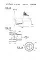
- FIG. 1shows a cross-sectional view along the center axis of the air passageway of a first embodiment of a detector in the form of a nasal cannula modified to incorporate the present invention
- FIG. 2shows the embodiment of FIG. 1 in use
- FIG. 3illustrates a block diagram of the Krasner Monitor which has been modified to incorporate the present invention so as to operate with the nasal cannula shown in FIG. 1;
- FIG. 4is a cross-sectional view along the center axis of the air passageway of a second embodiment of a nasal cannula incorporating the present invention
- FIG. 5shows a cross-sectional view along the center axis of the air passageway of a third embodiment of a nasal cannula incorporating the present invention
- FIG. 6is an enlarged perspective view of the insert prongs used in the FIG. 5 embodiment; application of which will be indicated in the claims.
- FIG. 7shows a frontal view of an oxygen mask incorporating the principles of the present invention.
- FIG. 8shows a perspective view of an acoustic endotracheal tube adapter incorporating the present invention and used with a standard endotracheal tube and a ventilator;
- FIG. 9is an enlarged perspective axial view of a first embodiment of the acoustic endotracheal tube adapter incorporating the present invention and used in FIG. 8;
- FIG. 10is a cross-sectional view taken along line 10--10 in FIG. 9;
- FIG. 11illustrates a block diagram of the Krasner Monitor which has been modified to incorporate the present invention so as to operate with the nasal cannula shown in FIGS. 9 and 10;
- FIG. 12shows a graph of amplitude vs. time of a typical respiration signal useful in understanding the operation of the FIG. 11 block diagram
- FIG. 13shows an enlarged perspective axial view of a second embodiment of the acoustic endotracheal tube adapter used in FIG. 8;
- FIG. 14is a cross-sectional view taken along line 14--14 in FIG. 13;
- FIG. 15is a cross-sectional view taken along line 15--15 in FIG. 13;
- FIG. 16is a block diagram of yet another embodiment of the Krasner Monitor which has been modified to incorporate the present invention.
- the devices showneach define a passageway which can be "connected" to the respiratory airway (either anatomically by insertion or near insertion of the device, into the body such as each of the nasal cannulas shown in FIGS. 1, 2, 4, and 5, or alternatively into a mask worn by the user such as shown in FIG. 9, or mechanically by connecting the device, such as each of the adapters shown generally in FIG. 10 and in greater detail in FIGS. 11-13 and 14-15, to breathing assistance apparatus, such as a ventilator).
- breathing assistance apparatussuch as a ventilator
- Each devicewhen so connected, produces during breathing a unique acoustical signature which enhances the signal-to-noise ratio for processing by, for example, the Krasner Monitor.
- these devicesare direction specific such that inhalation or exhalation can be readily and specifically distinguished and identified.
- the nasal cannula 10includes a hollow tubular body 12 having an air passageway 14, a closed end 16 and a closed end 18.
- Two nostril inserts 20radially extend from the tubular body between the ends 16 and 18. Inserts 20 are open at their outer extremeties at 22 and communicate with the air passageway 14 so that they can be inserted in or placed near the nostrils of the user.
- the cannulais provided with means for generating an acoustic signal within a preselected, relatively narrow band of frequencies and means for detecting this acoustic signal.
- the means for generating the acoustic signalis in the form of an acoustic resonant cavity 24 (sometimes referred to as a whistle), created by at least one aperture 26 provided between the nostril inserts 20 and the closed end 18, and a partial obstruction 28 partially extending into passageway 14 so as to create eddies in the resonant cavity 24 from the substantially laminar flow of air flowing in the passageway 14 from the inserts 20 preferably in response to exhalation by the user.
- the partial obstruction 28can take several different forms, as are known in whistle art. As shown in FIG. 1, the obstruction 28 is merely a lip extending from the edge of the aperture 26 nearest to the closed end 18 and terminating in a thin edge.
- the flow of airis substantially laminar in the narrow passageway until it reaches the narrowing created by the obstruction 28, wherein an instability or eddies are created in the closed ended resonant cavity between the obstruction 28 and the closed end 18.
- This instabilityproduces in the resonant cavity a narrow band tone or signal (within a bandwidth of frequencies) the frequency of which is a function of the flow rate.
- the tone frequencyincreases.
- the whistleis designed to produce tones for extremely low airflow rates, and with typical airflow rates associated with respiration the range of possible tones is contained within a limited range of frequencies. In most applications the amplitude of sound is below the auditory thresholds for humans so that the user will not hear the tone.
- the means for detecting the acoustic signalcomprises an acoustic signal pressure detector 30, such as a microphone for detecting the acoustic signal generated in the resonant cavity.
- the detector 30preferably forms the closed end 18.
- the detector 30provides an electrical signal representative of the acoustical signal generated in the cavity.
- the nasal cannula 10can be worn by a spontaneously breathing person by placing the cannala in or near the nostrils of the user.
- detector 30is preferably electrically connected (through leads 32 shown in FIG. 2) to apparatus constructed in accordance with the teachings of U.S Pat. No. 4,306,567, and modified in accordance with the present invention. More particularly, the detector 30 is connected to input amplifier 34 for amplifying and shaping the signals detected. Amplifier 34 is connected to the input of a wideband band pass filter 36. The latter is designed to pass those spectral portions of the signal detected which include the range of tones generated in the resonant cavity while at the same time blocking those spectral portions of the signal where most noise (generated in the environment as well as by motion artifacts) is present.
- the filter 36is preferably of the active type so as to provide gain depending upon the relative strength of the signal.
- Each filtermay, for example, be a state variable filter with a center frequency at the frequency generated by the detector 30 in response to the lowest velocity air flow detected.
- a typical center frequencyis between about 800 to 1200 Hz with the range of tones being generated by the detector being between about 800-1200 Hz at the low end and anywhere from about 1200-4000 Hz at the high end.
- the filtershould have a very steep skirt at its low frequency cut off (e.g., a slope of about 48 dB/octave), and roll off at about -12 dB/octave so that it passes portions of the spectral energy outside the resonant frequency of respiration as well as most of the environmental noise and noise associated with motion artifacts, but includes the spectral energy within the range of tones generated by the detector.
- the output of filter 36is connected to means 38 for locking onto the frequency of the tone being generated by the detector.
- the means 38may be any of various devices known for locking onto a narrow band signal, such as a tracking filter, or alternatively, a phase lock loop circuit, both of which are well known to those skilled in the art.
- the means 38locks onto the signal, and holds the signal even though the frequency of the signal typically shifts in a continous fashion from its lower frequency, e.g., 800-1200 Hz, to its upper frequency, e.g., 1200 Hz-4000 Hz., during exhalation.
- the output of means 38is connected to means 40 for demodulating the output of the signal so as to provide a signal representative of the envelope of the signal output of the means 38.
- Means 40is shown as including a D.C. rectifier 42, preferably a full wave rectifier, connected to receive the output of the means 38 and rectify the same.
- the rectified signalis then, in turn, applied to low pass filter 44.
- the latteris preferably designed to pass the envelope frequencies within the bandwidth of interest. Filter 44 should pass those frequencies below about 10 Hz although this can vary.
- the output of low pass filter 44is then applied to threshold detector 46.
- the lattermay also be in the form of a comparator whose threshold is set above ambient noise.
- each breathtakes a finite period of time, for humans typically greater than about 300-900 milliseconds, but not usually exceeding 2-3 seconds.
- Pulses derived from motion artifactsare typically of a relatively shorter duration, i.e., less than 300-400 milliseconds.
- means, preferably in the form of pulse discriminator 48are provided for discriminating between pulses of duration representative of less than a predetermined time period including pulses derived from motion artifacts, e.g., 400 milliseconds, and may also reject those exceeding a predetermined time period, e.g., 3 or 4 seconds.
- the output of the discriminator 48is a series or train of pulses, the repetition rate being the sensed respiration rate.
- the output of discriminator 48is applied to the one-shot multivibrator 50, which in turn provides a single pulse of fixed amplitude and a predetermined duration for each pulse received at its input.
- each output pulse of multivibrator 50has a finite amount of energy and is indicative of each respiration cycle.
- the output of multivibrator 50can be connected to the input of integrator 52. Since each pulse from multivibrator 50 contains the same amount of signal energy, the integrator will charge and discharge at a rate dependent on the repetition rate of the pulses which is a function of respiration rate.
- the voltage level of the outputcan be applied to a suitable display 54, such as a digital display, to indicate the respiration rate.
- the output of multivibrator 50can be applied to a light indicator 56 such as an LED (light emitting diode) display so that the latter is energized for each respiration cycle.
- the output of multivibrator 50is also connected so as to provide an apnea monitoring device. More specifically, the output of multivibrator 50 is connected to the input of apnea timer 58.
- the latterincludes integrator 60 connected to the inverting input of threshold amplifier 62.
- the integrator 58is set to charge and discharge at rates such that the output of the integrator will fall below the threshold level set at the noninverting input of amplifier 62 when no pulses are received from multivibrator 48 for a predetermined period of time.
- the output of amplifier 60then goes to some finite value and drives the alarm 62 giving a sonic or visual indication that the sensor no longer detects respiration.
- the cannula nostril inserts 20A and 20B of the cannula 10Aare isolated from one another by placing a closure 70 in the air passageway 14 of the cannula between the two nostril inserts.
- the end 16Ais open so that oxygen can, for example, be administered through the opening and through the one nostril insert 20A.
- At least a portion of the air flow in response to exhalationwill occur through the other insert 20B to the opposite end of the cannula through aperture 26 resulting in resonance occurring in the cavity 24 at the detector 30 as previously described.
- the nasal cannulahas its end 16B connected to a source of oxygen, while the other end 18B is closed.
- At least one insert prong 80extends through the wall of the cannula up through one of the nasal inserts 20B and preferably terminates at its end 82 just above the top edge of the insert. The opposite end of the prong 80 is connected to the detector 30.
- the prong 80is preferably a hollow tube open at its end 82 and has an internal diameter much smaller than the internal diameter of the insert 20B and passageway 14. As oxygen is supplied to the end 16B and through the passageway, the detector 30 will sense a relatively constant background noise, the characteristics of which are a function of flow rate. When the cannula 10B is placed on the user, in a manner similar to that shown in FIG. 2, the top end 82 of the prong will be disposed in or near a nostril of the user. During inhalation, the oxygen flowing through the cannula passageway will be inhaled by the user.
- the signal sensed by detector 30 in the FIG. 5 embodimentcan by processed by the Krasner Monitor in a manner hereinafter described with respect to those Figs.
- the principles of the present inventioncan be utilized in other devices which define an air passageway which can be connected to carry airflow responsive to respiration.
- the acoustic signal generator means and detectorcan be connected to an oxygen mask 90.
- the front of the maskis typically provided with a connector, generally indicated by numeral 92, for receiving a supply of oxygen.
- the maskis modified to include a connector 96 to receive the hollow tube 94, open at its connecting point to the connector 92 of the mask and closed off at its bottom end by a resonant cavity 24, which in turn is connected to the detector 30 for sensing the acoustic signal generated in the resonant cavity.
- a connector 96to receive the hollow tube 94, open at its connecting point to the connector 92 of the mask and closed off at its bottom end by a resonant cavity 24, which in turn is connected to the detector 30 for sensing the acoustic signal generated in the resonant cavity.
- a tuned acoustic signalwhilestle
- the detector 30will sense the acoustic signal in the manner previously described.
- FIG. 8Another example of a device which defines an air passageway, which in turn can be connected to carry airflow in response to respiration, is a device which is adapted to be connected between the user and respiration assistance apparatus, such as shown in FIG. 8.
- an adapter 100is connected between an endotracheal tube 102 and the T-piece connector 104, which in turn connects respiratory tubing to a ventilator 106 (or an anesthesia machine).
- Embodiments of the adapter 100are shown in FIGS. 9 and 10 and in FIGS. 13-15.
- the adapter 100Ais shown in detail.
- the adapter showncomprises an outer hollow tube 108 open at opposite ends 110 and 112.
- the interior of the outer hollow tubedefines the passageway 14C of the device.
- the outer tube 108is slightly tapered at the end 110 receiving air from the ventilator 106 so as to interface between the T piece connector and the endotracheal tube.
- a smaller inner hollow tube 114provided with a flared out opening at one end 116 and attached at its other end to detector 30, has inner and outer cross-sectional dimensions much smaller than those of the passageway.
- the smaller inner tubepreferably extends through the wall of the outer tube and is bent so that the end 116 of the inner tube faces in the direction opposite to the direction of airflow which occurs in response to exhalation by the user (and in the direction of air flow which occurs when air is supplied by the ventilator 106).
- the ventilatorwill assist breathing by forcing air into the lungs of a patient, forcing inhalation, with air being subsequently exhaled from the patient.
- the ventilatormay operate with each breadth of the patient but, more typically, will operate periodically, allowing the patient to breathe in an unassisted manner between each ventilator operation.
- the adapter 100Awill generate an acoustic signal with each exhalation.
- acoustic (or pressure) signals resulting from airflow from the ventilator (inhalation) and from the user (exhalation)are detected by the detector 30. Both inhalation and exhalation can produce similar acoustic signatures.
- a typical output signal of the detectore.g., a microphone
- the detector outputhas a bias potential a.
- the bias potentialdrops to c.
- the bias potentialjumps to level e.
- FIG. 11Apparatus for processing the detected signal is shown in FIG. 11.
- the apparatus of FIG. 11is a Krasner Monitor modified so as to further enhance the signal to noise ratio of the processed signal by using the signal information at one frequency (in this case the envelope of the signal shown in FIG. 12) to monitor the signal information at another frequency (in this case the signal representive of respiration contained in the envelope).
- the detector 30 shown in FIGS. 9 and 10may be connected in a suitable manner so that its output signal is used to determine the phase (i.e., inhalation or exhalation) of the respiratory cycle.
- the D.C. operating levels during inhalation (level c) and exhalation (level e)are shown in the example of FIG. 12.
- the output of detector 30is connected through its leads to the input amplifier 34 (previously described with respect to FIG. 3).
- the output of amplifier 34is connected to the input of a respiration filter 120.
- the latteris preferaby identical to the type of respiration filter disclosed in U.S. Pat. No. 4,306,567, except that the center frequency is preferably about 200 Hz.
- the respiration filteris preferably a band pass filter having a center frequency or maximum transmission at about 200 Hz.
- the specific design of the filtermay take the form of any one of several types of filters which are known in the art.
- the filteris preferably of the active type so as to provide a predetermined gain depending upon the relative of the signal.
- the filtermay be a variable state filter with a center frequency of about 200 Hz, and skirts preferably sloping at about 48 dB/octave, although this can vary.
- the filteris preferably designed to have a Q between about 10 and 100, with 10 being preferred, although the Q can also vary from this value.
- the output of respiration filter 120is connected to the input of the means 40 for demodulating the signal output of the filter, as previously described with respect to FIG. 3.
- the output of demodulator means 40is connected to the input of gate 122 for selectively transmitting only a predetermined portion of the signal in response to a control signal.
- the control signalis generated by connecting the output of detector 30 to the input of an automatic threshold detector 124.
- the lattergenerally transmits only portions of the signal sensed by the detector 30 which are above a predetermined threshold (shown as level A in FIG. 12 as being slightly below the bias level of the signal) so that substantially all of the portion of the signal associated with inhalation is not transmitted by the threshold detector 124.
- the output of detector 124is connected to the input of pulse width discriminator 128 for testing whether the level below the predetermined threshold level A stays below that level by a predetermined period of time (e.g., 0.5-1.0 seconds) so as to insure that inhalation occurred and to establish the expected occurrence of exhalation.
- This outputis connected to the input of a second threshold detector 130.
- the lattergenerally transmits only portions of the signal transmitted by the second detector 130 above a predetermined threshold (shown as level B in FIG.
- the output of detector 130is connected to the input of one shot multivibrator 132.
- the latterprovides a pulse of predetermined width in response to each leading edge of the output of detector 130.
- the output of multivibrator 132is applied to the control input of gate 122.
- the lattercan be a field effect transistor connected so that its gate electrode receives the control signal from multivibrator 132, which in turn makes the transistor conductive so that it transmits the signal output from the output of demodulator means 40 to the threshold detector 46.
- the latteris connected to the remainder of the system as shown in FIG. 3.
- the acoustic signal generated in response to respirationis sensed by detector 30, which in turn provides an output signal similar to the one shown in FIG. 12.
- detector 30At very low frequencies (i.e., typical frequencies associated with normal respiration rates such as those between 0.1 Hz to 1.0 Hz) the output of the detector 30 of the FIGS. 9 and 10 adapter behaves similar to a pressure detector although not identical.
- the detector 30generates the waveforms of FIG. 12 in response to each respiratory cycle.
- the bias leveldrops as is shown at b, while c indicates the duration of inhalation.
- the bias levelrapidly rises to a higher level e, the positive slope transition being indicated by d.
- the cyclerepeats itself.
- This signalis transmitted to the amplifier 34.
- the amplified output of amplifier 34is filtered by respiration filter 120 before being applied to the demodulating means 40.
- the output of means 40is essentially the envelope of the signal shown in FIG. 12.
- the signal output of detector 30is also applied to the automatic threshold detector 124 which senses that portion of the signal below the threshold level A.
- the remaining portion of the signal, above threshold level Ais transmitted to the discriminator 128. The latter tests whether the level of the signal below threshold level A is for a predetermined period of time, so as to insure that the inspiratory portion of the cycle has occurred.
- the remaining portion of the signalis transmitted to the second threshold detector 130 set to transmit those portions of the signal above threshold level B.
- the leading edge of this portion of the signal(part d of the signal above level B) will trigger one shot multivibrator 132.
- the latterprovides a pulse for a predetermined duration providing a window for a portion of the expiratory portion of the signal.
- the 200 Hz center frequency of the respiration filterrepresents the near-optimum signal-to-noise ratio associated with a ventilator-patient connection, and is outside of the resonant frequency of the respiratory tubing. The problem with using a single bandpass is that it might prove difficult to distinguish between inhalation and exhalation.
- the systemignores all signals until inhalation has been completed and exhalation has commenced. Since the time for the expected onset of exhalation is precisely known, i.e., at the end of inhalation, the requirement established in U.S. Pat. No. 4,306,567 for optimum signal-to-noise is enhanced by only looking at the expiratory portion of the cycle through a precise time window.
- the signal information carried by the envelope of the signal shown in FIG. 12is used to distinguish between inhalation and exhalation. As described, by sensing exhalation, if the endotracheal tube 102 of FIG.
- the alternative adapter 100Bincludes the outer tube 108 which is substantially identical to that shown in the adapter of FIGS. 9 and 10, and an inner hollow cylindrical tube 109 coaxially mounted in the outer tube and defining the air passageway 14D.
- a vortex shedding element 117preferably in the form of a cylindrical pin, is connected diametrically across the center interior portion of the inner tube 109.
- a thin hollow tube 118extends through the outer tube 108 and the inner tube 109. Tube 118 has an open end positioned just downstream (with respect to airflow in direction from the user during exhalation) and its other end connected to the detector 30.
- air flowing in response to exhalationwill be substantially laminar in the inner tube 109 until it strikes the vortex shedding element whereupon vortices are created downstream from the element 117.
- Such vorticeswill create an acoustic signal which is sensed by detector 30.
- the output signal of detector 30With the detector 30 positioned upstream with respect to airflow from the ventilator and downstream with respect to airflow in response to exhalation the output signal of detector 30 will be similar to that obtained from the resonant cavity 24 of the previously described embodiments employing the cavity.
- the apparatus of FIG. 3can be used to process the output signal of the detector 30 in the adapter shown in FIGS. 13-15.
- the respiration signalcan be processed by monitors of the Krasner type, other than those shown in FIGS. 3 and 11, without departing from the scope of the invention.
- the techniques shown in FIGS. 3 and 11have been combined in the system shown in FIG. 16.
- the output of detector 30is connected to the input of amplifier 34.
- the latterhas its output connected to the gate 122.
- the output of detector 30is connected to the automatic threshold detector 124, which in turn has its output connected to the input of pulse width discriminator 128.
- the latterhas its output connected to the input of the second threshold detector 130.
- Detector 130has its output connected to the input of one shot multivibrator 132, which in turn has its output connected to control the conduction of the gate 122.
- the output of gate 122is connected to the input of band pass filter 36, which in turn is connected to the means 38 for locking onto the tuned frequency signal.
- the output of means 38is connected to the demodulator means 40, with the remainder of the circuit identical to that shown in FIG. 3.
- detector 124, pulse width discriminator 128, detector 130 and multivibrator 132provide the control gating signal, as in the FIG. 11 system so that a window is provided during exhalation.
- This portionis filtered by filter 36 and tracked by the means 38, as described with respect to FIG. 3.
- the system of FIG. 16combines the techniques of both FIGS. 3 and 11.
- the output of the detector 30can be inverted. Similar signal processing would produce the desired result.
- Another modification which can be made to the systems shown in FIGS. 11 and 16,is that a derivative circuit for providing an output signal for positive going signals, i.e., portion d of the signal shown in FIG. 12, can be substituted for the threshold detector 124.
- the inventiontherefore provides a useful way of acquiring a physiological signal, such as that associated with respiration.
- the deviceis simple and relatively inexpensive to manufacture.
- the particular acoustic frequency of interest or bandpass of acoustic frequenciesis selected according to the requirements of the physiological signal and the environment from which it must be selected. In this way the precise frequency at which the Krasner Monitor is operated can be selected to optimize, as well as further enhance the signal-to-noise ratio.
Landscapes
- Health & Medical Sciences (AREA)
- Life Sciences & Earth Sciences (AREA)
- Biomedical Technology (AREA)
- Surgery (AREA)
- Pulmonology (AREA)
- Veterinary Medicine (AREA)
- Public Health (AREA)
- Engineering & Computer Science (AREA)
- General Health & Medical Sciences (AREA)
- Heart & Thoracic Surgery (AREA)
- Medical Informatics (AREA)
- Molecular Biology (AREA)
- Animal Behavior & Ethology (AREA)
- Physics & Mathematics (AREA)
- Physiology (AREA)
- Pathology (AREA)
- Biophysics (AREA)
- Measurement Of The Respiration, Hearing Ability, Form, And Blood Characteristics Of Living Organisms (AREA)
Abstract
Description
Claims (61)
Priority Applications (1)
| Application Number | Priority Date | Filing Date | Title |
|---|---|---|---|
| US06/409,306US4602644A (en) | 1982-08-18 | 1982-08-18 | Physiological detector and monitor |
Applications Claiming Priority (1)
| Application Number | Priority Date | Filing Date | Title |
|---|---|---|---|
| US06/409,306US4602644A (en) | 1982-08-18 | 1982-08-18 | Physiological detector and monitor |
Publications (1)
| Publication Number | Publication Date |
|---|---|
| US4602644Atrue US4602644A (en) | 1986-07-29 |
Family
ID=23619915
Family Applications (1)
| Application Number | Title | Priority Date | Filing Date |
|---|---|---|---|
| US06/409,306Expired - Fee RelatedUS4602644A (en) | 1982-08-18 | 1982-08-18 | Physiological detector and monitor |
Country Status (1)
| Country | Link |
|---|---|
| US (1) | US4602644A (en) |
Cited By (65)
| Publication number | Priority date | Publication date | Assignee | Title |
|---|---|---|---|---|
| WO1989009565A1 (en)* | 1988-04-15 | 1989-10-19 | Bowe Edwin A | Method and apparatus for inhalation of treating gas and sampling of exhaled gas for quantitative analysis |
| US4893630A (en)* | 1984-04-06 | 1990-01-16 | Trinity Computing Systems, Inc. | Apparatus and method for analyzing physiological conditions within an organ of a living body |
| EP0403324A1 (en)* | 1989-05-29 | 1990-12-19 | Societe Civile D'etudes Et De Recherche Revo'air | Moving air detector utilizing microwaves, especially for controlling and monitoring respiration |
| WO1991012051A1 (en)* | 1990-02-16 | 1991-08-22 | Hök Instrument Ab | Acoustic respiration detector |
| WO1991013575A1 (en)* | 1990-03-09 | 1991-09-19 | Leggett & Platt, Incorporated | Clinical bed |
| US5107831A (en)* | 1989-06-19 | 1992-04-28 | Bear Medical Systems, Inc. | Ventilator control system using sensed inspiratory flow rate |
| US5161541A (en)* | 1991-03-05 | 1992-11-10 | Edentec | Flow sensor system |
| US5251636A (en)* | 1991-03-05 | 1993-10-12 | Case Western Reserve University | Multiple thin film sensor system |
| US5335656A (en)* | 1988-04-15 | 1994-08-09 | Salter Laboratories | Method and apparatus for inhalation of treating gas and sampling of exhaled gas for quantitative analysis |
| US5513631A (en)* | 1995-07-21 | 1996-05-07 | Infrasonics, Inc. | Triggering of patient ventilator responsive to a precursor signal |
| US5573004A (en)* | 1994-10-06 | 1996-11-12 | Edentec Corporation | Electrically stable electrode and sensor apparatus |
| US5836302A (en)* | 1996-10-10 | 1998-11-17 | Ohmeda Inc. | Breath monitor with audible signal correlated to incremental pressure change |
| US6029665A (en)* | 1993-11-05 | 2000-02-29 | Resmed Limited | Determination of patency of airway |
| US6029660A (en)* | 1996-12-12 | 2000-02-29 | Resmed Limited | Substance delivery apparatus |
| US6076520A (en)* | 1997-05-12 | 2000-06-20 | Cooper; Emily L. | Device for nasal therapeutic inhalation |
| US6091973A (en)* | 1995-04-11 | 2000-07-18 | Resmed Limited | Monitoring the occurrence of apneic and hypopneic arousals |
| US6152129A (en)* | 1996-08-14 | 2000-11-28 | Resmed Limited | Determination of leak and respiratory airflow |
| US6155986A (en)* | 1995-06-08 | 2000-12-05 | Resmed Limited | Monitoring of oro-nasal respiration |
| US6182657B1 (en) | 1995-09-18 | 2001-02-06 | Resmed Limited | Pressure control in CPAP treatment or assisted respiration |
| US6213119B1 (en) | 1995-10-23 | 2001-04-10 | Resmed Limited | Inspiratory duration in CPAP or assisted respiration treatment |
| US6237592B1 (en) | 1995-07-03 | 2001-05-29 | Resmed Limited | Auto-calibration of pressure transducer offset |
| US6253764B1 (en) | 1996-05-08 | 2001-07-03 | Resmed, Ltd. | Control of delivery pressure in CPAP treatment or assisted respiration |
| US6299581B1 (en)* | 1992-05-07 | 2001-10-09 | New York University | Method and apparatus for optimizing the continuous positive airway pressure for treating obstructive sleep apnea |
| US6332463B1 (en) | 1995-09-15 | 2001-12-25 | Resmed Limited | Flow estimation and compensation of flow-induced pressure swings in CPAP treatment and assisted respiration |
| US20020017300A1 (en)* | 2000-06-13 | 2002-02-14 | Hickle Randall S. | Apparatus and method for mask free delivery of an inspired gas mixture and gas sampling |
| US6367474B1 (en) | 1997-11-07 | 2002-04-09 | Resmed Limited | Administration of CPAP treatment pressure in presence of APNEA |
| US6397841B1 (en) | 1997-06-18 | 2002-06-04 | Resmed Limited | Apparatus for supplying breathable gas |
| US20020124848A1 (en)* | 1987-06-26 | 2002-09-12 | Sullivan Colin Edward | Method and apparatus useful in the diagnosis of obstructive sleep apnea of a patient |
| US6532957B2 (en) | 1996-09-23 | 2003-03-18 | Resmed Limited | Assisted ventilation to match patient respiratory need |
| US6565517B1 (en)* | 1998-07-29 | 2003-05-20 | Rhinometrics A/S | Apparatus and methods for rhinomanometry |
| US6635021B1 (en)* | 1987-06-26 | 2003-10-21 | Resmed Limited | Method and apparatus useful in the diagnosis of obstructive sleep apnea of a patient |
| US20040016434A1 (en)* | 2002-07-25 | 2004-01-29 | Draeger Medical, Inc. | Ventilation sound detection system |
| US20040035431A1 (en)* | 2002-08-21 | 2004-02-26 | Wright Clifford A. | Ear cannula system and method of using same |
| US20040123866A1 (en)* | 1993-11-05 | 2004-07-01 | Michael Berthon-Jones | Determination of patency of the airway |
| US20040225226A1 (en)* | 2000-08-17 | 2004-11-11 | Ilife Systems, Inc. | System and method for detecting the onset of an obstructive sleep apnea event |
| US20050092321A1 (en)* | 2003-10-29 | 2005-05-05 | Airmatrix Technologies, Inc. | Method and system of sensing airflow and delivering therapeutic gas to a patient |
| US20050161049A1 (en)* | 2002-08-21 | 2005-07-28 | Medical Device Group, Inc., A California Corporation | Divided nasal cannula assembly |
| US7066180B2 (en)* | 2003-07-09 | 2006-06-27 | Airmatrix Technologies, Inc. | Method and system for measuring airflow of nares |
| US20060169281A1 (en)* | 2005-02-03 | 2006-08-03 | Aylsworth Alonzo C | Continuous flow selective delivery of therapeutic gas |
| US20080156326A1 (en)* | 2006-12-29 | 2008-07-03 | Philip Morris Usa Inc. | Bent capillary tube aerosol generator |
| US20080196724A1 (en)* | 1999-02-12 | 2008-08-21 | Hossein Nadjafizadeh | Gas Supply Device for Sleep Apnea |
| US20080295839A1 (en)* | 2007-06-01 | 2008-12-04 | Habashi Nader M | Ventilator Apparatus and System of Ventilation |
| US20080319333A1 (en)* | 2004-07-23 | 2008-12-25 | Intercure Ltd. | Apparatus and Method for Breathing Pattern Determination Using a Non-Contact Microphone |
| US20090165795A1 (en)* | 2007-12-31 | 2009-07-02 | Nellcor Puritan Bennett Llc | Method and apparatus for respiratory therapy |
| US20090173350A1 (en)* | 2008-01-04 | 2009-07-09 | Richard Swanson | Multipurpose cannula |
| US20100024820A1 (en)* | 1994-09-12 | 2010-02-04 | Guy Bourdon | Pressure-Controlled Breathing Aid |
| US20100078024A1 (en)* | 2008-09-30 | 2010-04-01 | Nellcor Puritan Bennett Llc | Breathing assistance system with multiple pressure sensors |
| EP2283773A1 (en)* | 2009-08-10 | 2011-02-16 | Koninklijke Philips Electronics N.V. | Processing a breathing signal |
| US7931023B2 (en)* | 1991-12-20 | 2011-04-26 | Resmed Limited | Patient interface assembly for CPAP respiratory apparatus |
| US20110257550A1 (en)* | 2010-03-20 | 2011-10-20 | Jay Choi | Method and Apparatus for Continuous Monitoring of Exhaled Carbon Dioxide |
| US20130068221A1 (en)* | 2010-04-22 | 2013-03-21 | Omar Mian | Gas flow indicator |
| US20130186399A1 (en)* | 2011-07-29 | 2013-07-25 | University Of Cincinnati | Acoustic pressure inducers and methods for treatment of obstructive sleep apnea |
| JP2014064675A (en)* | 2012-09-25 | 2014-04-17 | Yamaguchi Prefectural Industrial Technology Institute | Non-constraint apnea detection system, method therefor and program therefor |
| US8770199B2 (en) | 2012-12-04 | 2014-07-08 | Ino Therapeutics Llc | Cannula for minimizing dilution of dosing during nitric oxide delivery |
| US8844537B1 (en) | 2010-10-13 | 2014-09-30 | Michael T. Abramson | System and method for alleviating sleep apnea |
| US20140318536A1 (en)* | 2005-09-12 | 2014-10-30 | Mergenet Medicial, Inc. | Nasal cannula |
| US20150170630A1 (en)* | 2012-06-11 | 2015-06-18 | Prometheus Medical Innovations Llc | Ambient gas flow alarm |
| US9199053B1 (en)* | 2011-01-31 | 2015-12-01 | Breathe Technologies, Inc. | Methods, systems and devices for ventilation using a nasal ventilation mask with a manifold and internal compliant tube and nasal sealing cushion assembly |
| WO2017025050A1 (en)* | 2015-08-12 | 2017-02-16 | Su Chiachi | Respiratory function testing system and respiratory function testing method thereof |
| US9795756B2 (en) | 2012-12-04 | 2017-10-24 | Mallinckrodt Hospital Products IP Limited | Cannula for minimizing dilution of dosing during nitric oxide delivery |
| US9907511B2 (en)* | 2010-12-17 | 2018-03-06 | Koninklijke Philips N.V. | System and method of identifying breaths based solely on capnographic information |
| US20180064898A1 (en)* | 2015-03-31 | 2018-03-08 | Fisher & Paykel Healthcare Limited | Nasal cannula |
| CN108452410A (en)* | 2017-12-01 | 2018-08-28 | 广州康智件科技有限公司 | A kind of oxygen therapy monitoring system |
| CN109276788A (en)* | 2018-08-24 | 2019-01-29 | 广州康智件科技有限公司 | A method and device for collecting respiratory rate for oxygen inhalation monitoring |
| US20200001035A1 (en)* | 2018-06-27 | 2020-01-02 | Accutron, Inc. | Capnography tube fitting |
Citations (3)
| Publication number | Priority date | Publication date | Assignee | Title |
|---|---|---|---|---|
| US3566862A (en)* | 1968-08-01 | 1971-03-02 | Paul A Schuh | Respiration apparatus |
| US3884219A (en)* | 1973-04-02 | 1975-05-20 | Medical Monitor Systems | System for determining temperature and respiration rate |
| US4306567A (en)* | 1977-12-22 | 1981-12-22 | Krasner Jerome L | Detection and monitoring device |
- 1982
- 1982-08-18USUS06/409,306patent/US4602644A/ennot_activeExpired - Fee Related
Patent Citations (3)
| Publication number | Priority date | Publication date | Assignee | Title |
|---|---|---|---|---|
| US3566862A (en)* | 1968-08-01 | 1971-03-02 | Paul A Schuh | Respiration apparatus |
| US3884219A (en)* | 1973-04-02 | 1975-05-20 | Medical Monitor Systems | System for determining temperature and respiration rate |
| US4306567A (en)* | 1977-12-22 | 1981-12-22 | Krasner Jerome L | Detection and monitoring device |
Cited By (128)
| Publication number | Priority date | Publication date | Assignee | Title |
|---|---|---|---|---|
| US4893630A (en)* | 1984-04-06 | 1990-01-16 | Trinity Computing Systems, Inc. | Apparatus and method for analyzing physiological conditions within an organ of a living body |
| US6635021B1 (en)* | 1987-06-26 | 2003-10-21 | Resmed Limited | Method and apparatus useful in the diagnosis of obstructive sleep apnea of a patient |
| US20020124848A1 (en)* | 1987-06-26 | 2002-09-12 | Sullivan Colin Edward | Method and apparatus useful in the diagnosis of obstructive sleep apnea of a patient |
| US6770037B2 (en) | 1987-06-26 | 2004-08-03 | Resmed Limited | Method and apparatus useful in the diagnosis of obstructive sleep apnea of a patient |
| US20050283089A1 (en)* | 1987-06-26 | 2005-12-22 | Colin Sullivan | Method and apparatus useful in the diagnosis of obstructive sleep apnea of a patient |
| US7004908B2 (en) | 1987-06-26 | 2006-02-28 | Resmed Limited | Method and apparatus useful in the diagnosis of obstructive sleep apnea of a patient |
| US7141021B2 (en) | 1987-06-26 | 2006-11-28 | Resmed Limited | Method and apparatus useful in the diagnosis of obstructive sleep apnea of a patient |
| US20070051371A1 (en)* | 1987-06-26 | 2007-03-08 | Sullivan Colin E | Method and apparatus useful in the diagnosis of obstructive sleep apnea of a patient |
| AU605977B2 (en)* | 1988-04-15 | 1991-01-24 | Edwin A. Bowe | Method and apparatus for inhalation of treating gas and sampling of exhaled gas for quantitative analysis |
| WO1989009565A1 (en)* | 1988-04-15 | 1989-10-19 | Bowe Edwin A | Method and apparatus for inhalation of treating gas and sampling of exhaled gas for quantitative analysis |
| US5335656A (en)* | 1988-04-15 | 1994-08-09 | Salter Laboratories | Method and apparatus for inhalation of treating gas and sampling of exhaled gas for quantitative analysis |
| EP0403324A1 (en)* | 1989-05-29 | 1990-12-19 | Societe Civile D'etudes Et De Recherche Revo'air | Moving air detector utilizing microwaves, especially for controlling and monitoring respiration |
| US5107831A (en)* | 1989-06-19 | 1992-04-28 | Bear Medical Systems, Inc. | Ventilator control system using sensed inspiratory flow rate |
| US5195528A (en)* | 1990-02-16 | 1993-03-23 | Hok Instrument Ab | Acoustic respiration detector |
| WO1991012051A1 (en)* | 1990-02-16 | 1991-08-22 | Hök Instrument Ab | Acoustic respiration detector |
| WO1991013575A1 (en)* | 1990-03-09 | 1991-09-19 | Leggett & Platt, Incorporated | Clinical bed |
| US5062169A (en)* | 1990-03-09 | 1991-11-05 | Leggett & Platt, Incorporated | Clinical bed |
| US5558099A (en)* | 1991-03-05 | 1996-09-24 | Edentec, Inc. | Flow sensor system |
| US5394883A (en)* | 1991-03-05 | 1995-03-07 | Case Western Reserve University | Multiple thin film sensor system |
| US5161541A (en)* | 1991-03-05 | 1992-11-10 | Edentec | Flow sensor system |
| US5251636A (en)* | 1991-03-05 | 1993-10-12 | Case Western Reserve University | Multiple thin film sensor system |
| US7931023B2 (en)* | 1991-12-20 | 2011-04-26 | Resmed Limited | Patient interface assembly for CPAP respiratory apparatus |
| US7901361B2 (en) | 1992-05-07 | 2011-03-08 | New York University | Method and apparatus for optimizing the continuous positive airway pressure for treating obstructive sleep apnea |
| US6299581B1 (en)* | 1992-05-07 | 2001-10-09 | New York University | Method and apparatus for optimizing the continuous positive airway pressure for treating obstructive sleep apnea |
| US7320320B2 (en) | 1993-11-05 | 2008-01-22 | Resmed Limited | Determination of patency of the airway |
| US20110011402A1 (en)* | 1993-11-05 | 2011-01-20 | Michael Berthon-Jones | Distinguishing between closed and open airway apneas and treating patients accordingly |
| US20100242965A1 (en)* | 1993-11-05 | 2010-09-30 | Michael Berthon-Jones | Distinguishing between closed and open airway apneas and treating patients accordingly |
| US6138675A (en)* | 1993-11-05 | 2000-10-31 | Resmed Ltd. | Determination of the occurrence of an apnea |
| US8360060B2 (en) | 1993-11-05 | 2013-01-29 | Resmed Limited | Distinguishing between closed and open airway apneas and treating patients accordingly |
| US7730886B2 (en) | 1993-11-05 | 2010-06-08 | Resmed Limited | Determination of patency of the airway |
| US6029665A (en)* | 1993-11-05 | 2000-02-29 | Resmed Limited | Determination of patency of airway |
| US8381722B2 (en) | 1993-11-05 | 2013-02-26 | Resmed Limited | Distinguishing between closed and open airway apneas and treating patients accordingly |
| US20080163873A1 (en)* | 1993-11-05 | 2008-07-10 | Michael Berthon-Jones | Determination of patency of the airway |
| US20040123866A1 (en)* | 1993-11-05 | 2004-07-01 | Michael Berthon-Jones | Determination of patency of the airway |
| US8752547B2 (en) | 1993-11-05 | 2014-06-17 | Resmed Limited | Distinguishing between closed and open airway apneas and treating patients accordingly |
| US8573206B2 (en) | 1994-09-12 | 2013-11-05 | Covidien Lp | Pressure-controlled breathing aid |
| US20100024820A1 (en)* | 1994-09-12 | 2010-02-04 | Guy Bourdon | Pressure-Controlled Breathing Aid |
| US5573004A (en)* | 1994-10-06 | 1996-11-12 | Edentec Corporation | Electrically stable electrode and sensor apparatus |
| US6363270B1 (en) | 1995-04-11 | 2002-03-26 | Resmed Limited | Monitoring the occurrence of apneic and hypopneic arousals |
| US6091973A (en)* | 1995-04-11 | 2000-07-18 | Resmed Limited | Monitoring the occurrence of apneic and hypopneic arousals |
| US6155986A (en)* | 1995-06-08 | 2000-12-05 | Resmed Limited | Monitoring of oro-nasal respiration |
| US6237592B1 (en) | 1995-07-03 | 2001-05-29 | Resmed Limited | Auto-calibration of pressure transducer offset |
| US5513631A (en)* | 1995-07-21 | 1996-05-07 | Infrasonics, Inc. | Triggering of patient ventilator responsive to a precursor signal |
| US6332463B1 (en) | 1995-09-15 | 2001-12-25 | Resmed Limited | Flow estimation and compensation of flow-induced pressure swings in CPAP treatment and assisted respiration |
| US6526974B1 (en) | 1995-09-18 | 2003-03-04 | John William Ernest Brydon | Pressure control in CPAP treatment or assisted respiration |
| US6182657B1 (en) | 1995-09-18 | 2001-02-06 | Resmed Limited | Pressure control in CPAP treatment or assisted respiration |
| US6213119B1 (en) | 1995-10-23 | 2001-04-10 | Resmed Limited | Inspiratory duration in CPAP or assisted respiration treatment |
| US6253764B1 (en) | 1996-05-08 | 2001-07-03 | Resmed, Ltd. | Control of delivery pressure in CPAP treatment or assisted respiration |
| US6152129A (en)* | 1996-08-14 | 2000-11-28 | Resmed Limited | Determination of leak and respiratory airflow |
| US6279569B1 (en) | 1996-08-14 | 2001-08-28 | Resmed Limited | Determination of leak and respiratory airflow |
| US7137389B2 (en) | 1996-09-23 | 2006-11-21 | Resmed Limited | Method and apparatus for determining instantaneous inspired volume of a subject during ventilatory assistance |
| US8733351B2 (en) | 1996-09-23 | 2014-05-27 | Resmed Limited | Method and apparatus for providing ventilatory assistance |
| US8051853B2 (en) | 1996-09-23 | 2011-11-08 | Resmed Limited | Method and apparatus for providing ventilatory assistance |
| US6810876B2 (en) | 1996-09-23 | 2004-11-02 | Resmed Ltd. | Assisted ventilation to match patient respiratory need |
| US6532957B2 (en) | 1996-09-23 | 2003-03-18 | Resmed Limited | Assisted ventilation to match patient respiratory need |
| US7644713B2 (en) | 1996-09-23 | 2010-01-12 | Resmed Limited | Method and apparatus for determining instantaneous leak during ventilatory assistance |
| US6688307B2 (en) | 1996-09-23 | 2004-02-10 | Resmed Limited | Methods and apparatus for determining instantaneous elastic recoil and assistance pressure during ventilatory support |
| US9974911B2 (en) | 1996-09-23 | 2018-05-22 | Resmed Limited | Method and apparatus for providing ventilatory assistance |
| US5836302A (en)* | 1996-10-10 | 1998-11-17 | Ohmeda Inc. | Breath monitor with audible signal correlated to incremental pressure change |
| US6029660A (en)* | 1996-12-12 | 2000-02-29 | Resmed Limited | Substance delivery apparatus |
| US6076520A (en)* | 1997-05-12 | 2000-06-20 | Cooper; Emily L. | Device for nasal therapeutic inhalation |
| US6397841B1 (en) | 1997-06-18 | 2002-06-04 | Resmed Limited | Apparatus for supplying breathable gas |
| US9526855B2 (en) | 1997-11-07 | 2016-12-27 | Resmed Limited | Administration of CPAP treatment pressure in presence of apnea |
| US8684000B2 (en) | 1997-11-07 | 2014-04-01 | Resmed Limited | Administration of CPAP treatment pressure in presence of apnea |
| US6367474B1 (en) | 1997-11-07 | 2002-04-09 | Resmed Limited | Administration of CPAP treatment pressure in presence of APNEA |
| US6565517B1 (en)* | 1998-07-29 | 2003-05-20 | Rhinometrics A/S | Apparatus and methods for rhinomanometry |
| US20080196724A1 (en)* | 1999-02-12 | 2008-08-21 | Hossein Nadjafizadeh | Gas Supply Device for Sleep Apnea |
| US7992557B2 (en) | 1999-02-12 | 2011-08-09 | Covidien Ag | Gas supply device for sleep apnea |
| US20020017300A1 (en)* | 2000-06-13 | 2002-02-14 | Hickle Randall S. | Apparatus and method for mask free delivery of an inspired gas mixture and gas sampling |
| US7152604B2 (en)* | 2000-06-13 | 2006-12-26 | Scott Laboratories, Inc. | Apparatus and method for mask free delivery of an inspired gas mixture and gas sampling |
| US20040225226A1 (en)* | 2000-08-17 | 2004-11-11 | Ilife Systems, Inc. | System and method for detecting the onset of an obstructive sleep apnea event |
| US7819823B2 (en)* | 2000-08-17 | 2010-10-26 | Sleep Methods, Inc. | System and method for detecting the onset of an obstructive sleep apnea event |
| US20040016434A1 (en)* | 2002-07-25 | 2004-01-29 | Draeger Medical, Inc. | Ventilation sound detection system |
| US6863068B2 (en) | 2002-07-25 | 2005-03-08 | Draeger Medical, Inc. | Ventilation sound detection system |
| US20050161049A1 (en)* | 2002-08-21 | 2005-07-28 | Medical Device Group, Inc., A California Corporation | Divided nasal cannula assembly |
| US20040035431A1 (en)* | 2002-08-21 | 2004-02-26 | Wright Clifford A. | Ear cannula system and method of using same |
| US6986353B2 (en) | 2002-08-21 | 2006-01-17 | Medical Device Group, Inc. | Divided nasal cannula assembly |
| US7066180B2 (en)* | 2003-07-09 | 2006-06-27 | Airmatrix Technologies, Inc. | Method and system for measuring airflow of nares |
| WO2005044331A3 (en)* | 2003-10-29 | 2006-03-09 | Airmatrix Technologies Inc | Method and system of sensing a patient’s airflow |
| US20050092321A1 (en)* | 2003-10-29 | 2005-05-05 | Airmatrix Technologies, Inc. | Method and system of sensing airflow and delivering therapeutic gas to a patient |
| US7007692B2 (en)* | 2003-10-29 | 2006-03-07 | Airmatrix Technologies, Inc. | Method and system of sensing airflow and delivering therapeutic gas to a patient |
| US9642557B2 (en) | 2004-07-23 | 2017-05-09 | 2Breathe Technologies Ltd. | Apparatus and method for breathing pattern determination using a non-contact microphone |
| US7850619B2 (en)* | 2004-07-23 | 2010-12-14 | Intercure Ltd. | Apparatus and method for breathing pattern determination using a non-contact microphone |
| US20080319333A1 (en)* | 2004-07-23 | 2008-12-25 | Intercure Ltd. | Apparatus and Method for Breathing Pattern Determination Using a Non-Contact Microphone |
| US20060169281A1 (en)* | 2005-02-03 | 2006-08-03 | Aylsworth Alonzo C | Continuous flow selective delivery of therapeutic gas |
| US20140318536A1 (en)* | 2005-09-12 | 2014-10-30 | Mergenet Medicial, Inc. | Nasal cannula |
| US11883601B2 (en) | 2005-09-12 | 2024-01-30 | ResMed Pty Ltd | Nasal cannula |
| US10675427B2 (en)* | 2005-09-12 | 2020-06-09 | Robert M. Landis | Nasal cannula |
| US11596758B2 (en) | 2005-09-12 | 2023-03-07 | ResMed Pty Ltd | Nasal cannula |
| US9061300B2 (en)* | 2006-12-29 | 2015-06-23 | Philip Morris Usa Inc. | Bent capillary tube aerosol generator |
| US20080156326A1 (en)* | 2006-12-29 | 2008-07-03 | Philip Morris Usa Inc. | Bent capillary tube aerosol generator |
| US20080295839A1 (en)* | 2007-06-01 | 2008-12-04 | Habashi Nader M | Ventilator Apparatus and System of Ventilation |
| US20090165795A1 (en)* | 2007-12-31 | 2009-07-02 | Nellcor Puritan Bennett Llc | Method and apparatus for respiratory therapy |
| US8683998B2 (en) | 2008-01-04 | 2014-04-01 | Koninklijke Philips N.V. | Multipurpose cannula |
| US20090173350A1 (en)* | 2008-01-04 | 2009-07-09 | Richard Swanson | Multipurpose cannula |
| US20100078024A1 (en)* | 2008-09-30 | 2010-04-01 | Nellcor Puritan Bennett Llc | Breathing assistance system with multiple pressure sensors |
| US8302602B2 (en) | 2008-09-30 | 2012-11-06 | Nellcor Puritan Bennett Llc | Breathing assistance system with multiple pressure sensors |
| US9649458B2 (en) | 2008-09-30 | 2017-05-16 | Covidien Lp | Breathing assistance system with multiple pressure sensors |
| EP2283773A1 (en)* | 2009-08-10 | 2011-02-16 | Koninklijke Philips Electronics N.V. | Processing a breathing signal |
| US20110257550A1 (en)* | 2010-03-20 | 2011-10-20 | Jay Choi | Method and Apparatus for Continuous Monitoring of Exhaled Carbon Dioxide |
| US10828439B2 (en) | 2010-04-22 | 2020-11-10 | Swansea University | Gas flow indicator |
| US20130068221A1 (en)* | 2010-04-22 | 2013-03-21 | Omar Mian | Gas flow indicator |
| US8844537B1 (en) | 2010-10-13 | 2014-09-30 | Michael T. Abramson | System and method for alleviating sleep apnea |
| US9763767B2 (en) | 2010-10-13 | 2017-09-19 | Michael T. Abramson | System and method for alleviating sleep apnea |
| US9907511B2 (en)* | 2010-12-17 | 2018-03-06 | Koninklijke Philips N.V. | System and method of identifying breaths based solely on capnographic information |
| US9199053B1 (en)* | 2011-01-31 | 2015-12-01 | Breathe Technologies, Inc. | Methods, systems and devices for ventilation using a nasal ventilation mask with a manifold and internal compliant tube and nasal sealing cushion assembly |
| US8967143B2 (en)* | 2011-07-29 | 2015-03-03 | University Of Cincinnati | Acoustic pressure inducers and methods for treatment of obstructive sleep apnea |
| US20130186399A1 (en)* | 2011-07-29 | 2013-07-25 | University Of Cincinnati | Acoustic pressure inducers and methods for treatment of obstructive sleep apnea |
| US9489935B2 (en)* | 2012-06-11 | 2016-11-08 | Prometheus Medical Innovations Llc | Ambient gas flow alarm |
| US20150170630A1 (en)* | 2012-06-11 | 2015-06-18 | Prometheus Medical Innovations Llc | Ambient gas flow alarm |
| JP2014064675A (en)* | 2012-09-25 | 2014-04-17 | Yamaguchi Prefectural Industrial Technology Institute | Non-constraint apnea detection system, method therefor and program therefor |
| US10556082B2 (en) | 2012-12-04 | 2020-02-11 | Mallinckrodt Hospital Products IP Limited | Cannula for minimizing dilution of dosing during nitric oxide delivery |
| US9795756B2 (en) | 2012-12-04 | 2017-10-24 | Mallinckrodt Hospital Products IP Limited | Cannula for minimizing dilution of dosing during nitric oxide delivery |
| US10130783B2 (en) | 2012-12-04 | 2018-11-20 | Mallinckrodt Hospital Products IP Limited | Cannula for minimizing dilution of dosing during nitric oxide delivery |
| US9550039B2 (en) | 2012-12-04 | 2017-01-24 | Mallinckrodt Hospital Products IP Limited | Cannula for minimizing dilution of dosing during nitric oxide delivery |
| US9032959B2 (en) | 2012-12-04 | 2015-05-19 | Ino Therapeutics Llc | Cannula for minimizing dilution of dosing during nitric oxide delivery |
| US8770199B2 (en) | 2012-12-04 | 2014-07-08 | Ino Therapeutics Llc | Cannula for minimizing dilution of dosing during nitric oxide delivery |
| US10918819B2 (en) | 2012-12-04 | 2021-02-16 | Mallinckrodt Hospital Products IP Limited | Cannula for minimizing dilution of dosing during nitric oxide delivery |
| US12214135B2 (en) | 2015-03-31 | 2025-02-04 | Fisher & Paykel Healthcare Limited | Nasal cannula |
| US11420002B2 (en)* | 2015-03-31 | 2022-08-23 | Fisher & Paykel Healthcare Limited | Nasal cannula |
| US20180064898A1 (en)* | 2015-03-31 | 2018-03-08 | Fisher & Paykel Healthcare Limited | Nasal cannula |
| WO2017025050A1 (en)* | 2015-08-12 | 2017-02-16 | Su Chiachi | Respiratory function testing system and respiratory function testing method thereof |
| CN108452410A (en)* | 2017-12-01 | 2018-08-28 | 广州康智件科技有限公司 | A kind of oxygen therapy monitoring system |
| CN108452410B (en)* | 2017-12-01 | 2024-03-22 | 广州康智件科技有限公司 | Monitoring system for oxygen therapy |
| US11696996B2 (en)* | 2018-06-27 | 2023-07-11 | Hu-Friedy Mfg. Co., Llc | Capnography tube fitting |
| US20200001035A1 (en)* | 2018-06-27 | 2020-01-02 | Accutron, Inc. | Capnography tube fitting |
| CN109276788B (en)* | 2018-08-24 | 2024-12-27 | 广州康智件科技有限公司 | A respiratory rate acquisition method and device for oxygen inhalation monitoring |
| CN109276788A (en)* | 2018-08-24 | 2019-01-29 | 广州康智件科技有限公司 | A method and device for collecting respiratory rate for oxygen inhalation monitoring |
Similar Documents
| Publication | Publication Date | Title |
|---|---|---|
| US4602644A (en) | Physiological detector and monitor | |
| US4306567A (en) | Detection and monitoring device | |
| JP3737121B2 (en) | Apparatus and method for pressure and temperature waveform analysis | |
| US4452252A (en) | Non-invasive method for monitoring cardiopulmonary parameters | |
| US6375623B1 (en) | Determination of Apnea type | |
| US6224560B1 (en) | Flow restrictor for measuring respiratory parameters | |
| US9427539B2 (en) | System and method for diagnosis and treatment of a breathing pattern of a patient | |
| US6155986A (en) | Monitoring of oro-nasal respiration | |
| JPH0580214B2 (en) | ||
| US7976470B2 (en) | Apnea type determining apparatus and method | |
| CA2327809A1 (en) | Determination of apnea and hypopnea | |
| US20040233058A1 (en) | Respiration monitoring equipment | |
| US20100036266A1 (en) | Device and method for detecting heart beats using airway pressure | |
| CA2447705A1 (en) | A nasal cannula apnea detection device | |
| US5685318A (en) | Method and apparatus for detecting quick movement artifact in impedance respiration signals | |
| US4475559A (en) | Apparatus and method for detecting apnea | |
| CA2262236A1 (en) | Phonospirometry for non-invasive monitoring of respiration | |
| JP2628690B2 (en) | Respiratory rate monitor | |
| Vegfors et al. | Presentation and evaluation of a new optical sensor for respiratory rate monitoring | |
| GB2055046A (en) | Determining hypersensitivity of the respiratory system | |
| CA1216635A (en) | Surface inductive plethysmography | |
| US4597394A (en) | Method for noninvasively monitoring mouth volume | |
| WO1987000415A1 (en) | A device for supervision of the respiration of infants | |
| JPS6179445A (en) | Respiration detector, respiration speed monitor and physiological rithm function monitor of living body | |
| Hök et al. | A new respiratory rate monitor: development and initial clinical experience |
Legal Events
| Date | Code | Title | Description |
|---|---|---|---|
| AS | Assignment | Owner name:PLASMEDICS, INC.; ENGLEWOOD, CO. A CORP OF CO. Free format text:ASSIGNMENT OF ASSIGNORS INTEREST.;ASSIGNORS:DI BENEDETTO, JOHN P.;KRASNER, JEROME L.;REEL/FRAME:004122/0653;SIGNING DATES FROM 19830407 TO 19830425 | |
| AS | Assignment | Owner name:KRASNER, JEROME L., DR., Free format text:ASSIGNMENT OF ASSIGNORS INTEREST.;ASSIGNOR:PLASMEDICS, INC.;REEL/FRAME:004782/0610 Effective date:19870501 Owner name:CLINICAL DEVELOPMENT CORPORATION Free format text:ASSIGNMENT OF ASSIGNORS INTEREST.;ASSIGNORS:KRASNER, JEROME L.;DIBENEDETTO, JOHN P.;REEL/FRAME:004782/0631 Effective date:19871026 | |
| FEPP | Fee payment procedure | Free format text:PAYOR NUMBER ASSIGNED (ORIGINAL EVENT CODE: ASPN); ENTITY STATUS OF PATENT OWNER: LARGE ENTITY | |
| FPAY | Fee payment | Year of fee payment:4 | |
| REMI | Maintenance fee reminder mailed | ||
| LAPS | Lapse for failure to pay maintenance fees | ||
| FP | Lapsed due to failure to pay maintenance fee | Effective date:19940803 | |
| STCH | Information on status: patent discontinuation | Free format text:PATENT EXPIRED DUE TO NONPAYMENT OF MAINTENANCE FEES UNDER 37 CFR 1.362 |