US4602127A - Diagnostic data recorder - Google Patents
Diagnostic data recorderDownload PDFInfo
- Publication number
- US4602127A US4602127AUS06/588,004US58800484AUS4602127AUS 4602127 AUS4602127 AUS 4602127AUS 58800484 AUS58800484 AUS 58800484AUS 4602127 AUS4602127 AUS 4602127A
- Authority
- US
- United States
- Prior art keywords
- data
- vehicle
- controller
- telephone
- invention according
- Prior art date
- Legal status (The legal status is an assumption and is not a legal conclusion. Google has not performed a legal analysis and makes no representation as to the accuracy of the status listed.)
- Expired - Lifetime
Links
- 238000004891communicationMethods0.000claimsabstractdescription79
- 230000006854communicationEffects0.000claimsabstractdescription78
- 238000012545processingMethods0.000claimsabstractdescription70
- 239000004020conductorSubstances0.000claimsdescription35
- 238000000034methodMethods0.000claimsdescription7
- 238000012546transferMethods0.000claimsdescription4
- 230000002457bidirectional effectEffects0.000claimsdescription3
- 230000008054signal transmissionEffects0.000claims1
- 230000015654memoryEffects0.000description12
- 230000006870functionEffects0.000description11
- 230000005540biological transmissionEffects0.000description9
- 230000005236sound signalEffects0.000description7
- 238000003745diagnosisMethods0.000description6
- 239000000203mixtureSubstances0.000description5
- 238000004458analytical methodMethods0.000description4
- 238000010586diagramMethods0.000description4
- 239000000446fuelSubstances0.000description4
- 230000008901benefitEffects0.000description3
- 239000003990capacitorSubstances0.000description3
- 230000000881depressing effectEffects0.000description3
- 238000012360testing methodMethods0.000description3
- 230000008859changeEffects0.000description2
- 235000019504cigarettesNutrition0.000description2
- 239000007789gasSubstances0.000description2
- 230000007257malfunctionEffects0.000description2
- 238000012986modificationMethods0.000description2
- 230000004048modificationEffects0.000description2
- 230000007704transitionEffects0.000description2
- WRRSFOZOETZUPG-FFHNEAJVSA-N(4r,4ar,7s,7ar,12bs)-9-methoxy-3-methyl-2,4,4a,7,7a,13-hexahydro-1h-4,12-methanobenzofuro[3,2-e]isoquinoline-7-ol;hydrateChemical compoundO.C([C@H]1[C@H](N(CC[C@@]112)C)C3)=C[C@H](O)[C@@H]1OC1=C2C3=CC=C1OCWRRSFOZOETZUPG-FFHNEAJVSA-N0.000description1
- 230000003321amplificationEffects0.000description1
- QVGXLLKOCUKJST-UHFFFAOYSA-Natomic oxygenChemical compound[O]QVGXLLKOCUKJST-UHFFFAOYSA-N0.000description1
- 230000007175bidirectional communicationEffects0.000description1
- 238000004590computer programMethods0.000description1
- 239000002826coolantSubstances0.000description1
- 239000013078crystalSubstances0.000description1
- 238000007405data analysisMethods0.000description1
- 230000000994depressogenic effectEffects0.000description1
- 238000007519figuringMethods0.000description1
- 238000005259measurementMethods0.000description1
- 239000002991molded plasticSubstances0.000description1
- 230000007935neutral effectEffects0.000description1
- 238000003199nucleic acid amplification methodMethods0.000description1
- 239000001301oxygenSubstances0.000description1
- 229910052760oxygenInorganic materials0.000description1
- 230000002093peripheral effectEffects0.000description1
- 230000001105regulatory effectEffects0.000description1
- 230000008439repair processEffects0.000description1
- 230000001360synchronised effectEffects0.000description1
- 230000000007visual effectEffects0.000description1
Images


Classifications
- G—PHYSICS
- G01—MEASURING; TESTING
- G01M—TESTING STATIC OR DYNAMIC BALANCE OF MACHINES OR STRUCTURES; TESTING OF STRUCTURES OR APPARATUS, NOT OTHERWISE PROVIDED FOR
- G01M15/00—Testing of engines
- G01M15/04—Testing internal-combustion engines
- G01M15/05—Testing internal-combustion engines by combined monitoring of two or more different engine parameters
- G—PHYSICS
- G01—MEASURING; TESTING
- G01M—TESTING STATIC OR DYNAMIC BALANCE OF MACHINES OR STRUCTURES; TESTING OF STRUCTURES OR APPARATUS, NOT OTHERWISE PROVIDED FOR
- G01M17/00—Testing of vehicles
- G01M17/007—Wheeled or endless-tracked vehicles
Definitions
- This specificationincludes a microfiche appendix having two microfiche with one hundred and three frames.
- the present inventionrelates generally to vehicular diagnostic systems and particularly to a vehicular diagnostic system employing a portable communications control station.
- ACLAssembly Line Communications Link
- ECMelectronic control module
- hand held display toolshave been employed to selectively display the value or status of individual parameters.
- An example of such display toolsare the "Mini-Scanner” model 5247 and the “Multi-Scanner” model 3818 display tools marketed by Micro Processor Systems, Inc., Sterling Heights, Mich. Each of these tools provide one connector which is used to obtain the parameter data from the ALCL terminal and another connector which is adapted to draw electrical power from the vehicle cigarette lighter. These tools also provide switches to adjust the tool to the appropriate vehicle model and select the parameter desired to be displayed on the light emitting diode (LED) display of the tool.
- a "Video Scanner" circuit designed by Micro Processor Systems, Inc., for use in connection with an engine analyzer consolehas been employed to simultaneously display all of the parameter data available on the cathode ray tube (CRT) of the engine analyzer.
- CTRcathode ray tube
- the present inventionprovides a vehicular diagnostic system which generally comprises a portable communications control station and a remote data processor station.
- the control stationincludes a portable communications controller which comprises means for connecting the controller to a vehicle data link terminal capable of supplying parameter data monitored by the vehicle computer, means for connecting the controller to a source of electrical power in the vehicle, microcomputer means for enabling the flow of the parameter data through the data link terminal and for composing the data parameter data into a predetermined data stream, means for recording the data stream, and means for connecting the controller to a telephone line and for transmitting the data stream through the telephone line to the remote data processor station.
- Both the control station and the remote data processor stationinclude telephone communication means for enabling both voice and data communication transfer on an alternative basis between the control station and the data processor station.
- the present inventionalso provides a method of transferring parameter data, which generally comprises the steps of enabling the flow of the parameter data to the controller, composing the data into a predetermined data stream having at least one word for permitting the validity of the parameter data to be determined, and recording the data stream on magnetic tape.
- This methodalso includes the steps of playing back the recorded data stream, determining the validity of the recorded parameter data, and transmitting this data through a telephone line to the remote data processing station.
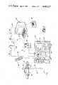
- FIG. 1is a diagrammatic view of a vehicular diagnostic system in accordance with the present invention.
- FIG. 2is a front elevation view of the display device shown in FIG. 1.
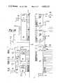
- FIGS. 3A-3Crepresent a schematic diagram of the portable communications controller shown in FIG. 1.
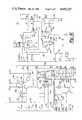
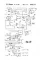
- FIGS. 4A-4Bare schematic diagrams of a communications circuit forming part of the remote data processor shown in FIG. 1.
- the diagnostic system 10generally comprises a portable communications control station 12 and remote data processing station 14.
- the control station 12is adapted to be employed in connection with a vehicle 16 which is equipped with an on-board computer 17 or other data acquisition system that permits access to one or more of the operating parameters being monitored in the vehicle.
- the vehicle 16could be a General Motors automobile which is equipped with an ECM and an ALCL terminal for gaining access to the parameters monitored by the ECM.
- the present inventionis not limited to any particular vehicle manufacturer, vehicle type or model year, or vehicle computer system, and that one of the advantages of the present invention is its versatility.
- the control station 12features a novel communications controller 18 which is conveniently housed in a molded plastic carrying case 20 of which only the bottom portion is shown for illustration purposes.
- the controller 18provides for two connector cables 22 and 24 which are used to connect the controller to the vehicle 16.
- the connector cable 22is used to connect the controller 18 to a suitable vehicle data terminal 23, such as an ALCL terminal, which is capable of supplying data representative of the value or status of one or more of the operating parameters monitored by the vehicle computer 17.
- the connector cable 24is used to connect the controller 18 to the vehicle cigarette lighter 25 or other appropriate source of electrical power in the vehicle 16.
- controller 18could be modified to include its own self-contained source of electrical power, such a feature is considered unnecessary in view of the relatively low power consumption requirements of the control station 12 and in view of the fact that electrical power from the vehicle battery or alternator will also have to be supplied to the vehicle computer in order to obtain the parameter data needed for diagnosis. Accordingly, in the preferred embodiment all of the electrical power required to operate the controller 18 is provided by the vehicle.
- the controller 18is adapted to transmit an enable signal along the connector cable 22 which will cause the vehicle computer to present the parameter data at the data link terminal in the vehicle 16 for transmission to the controller through the cable 22.
- the controllerhas the capability to direct this data to three different places.
- the controller 18includes a cassette recorder 26 which can be used to store the parameter data on magnetic tape.
- the controller 18includes a pair of telecommunication terminals 28 and 30 which can be used to transmit the data to the remote data processor station 14 via telephone communication, as will be more fully described below.
- the controller 18includes a display terminal 32 for transmitting the data to a display device, such as mini-scanner display device 34.
- the controller 18is capable of concomitantly recording the data, transmitting the data to the remote data processor station 14, and transmitting the data to the display device 34. Additionally, the controller 18 is also capable of first recording the data, and then transmitting the recorded data to the remote data processor station 14 and/or transmitting this data to the display device 34 during a play back mode. Similarly, the parameter data may be recorded and/or transmitted to the remote data processor station 14 without the use of the display device 34.
- the control station 12also includes a conventional telephone 36 which is connected to the telecommunications terminal 28 of the controller 18 to establish telephonic communication with the remote data processing station 14.
- a conventional telephone systemwhich is connected to the telecommunications terminal 28 of the controller 18 to establish telephonic communication with the remote data processing station 14.
- Both voice and data communicationmay be transmitted between the control station 12 and the data processing station 14 via a conventional telephone system, or alternatively along a local telephone loop.
- a telephone extension line 38is connected at one end to the telecommunications terminal 30 and connected to a conventional telephone wall plug 40 at the other end. Thereafter the voice or data communication is transferred, via the telephone system's telephone lines 42, microwave transmitters and so forth, to the remote data processing station 14.
- another telephone extension line 44is connected at one end to a telephone wall plug 46 and at the other end to a computer terminal 48.
- a conventional speaker phone 50 or other telephoneis also connected to the computer terminal 48 to permit voice communication at the data processing station 14.
- the keyboard 52 of the computer terminalmay be used to enter and automatically dial the telephone number of the control station telephone 36 in order to initiate telephone communications at the data processing station 14.
- a local telephone loopmay also be employed in an application where the vehicle 16 is located within a few hundred feet of the data processing station 14.
- An example of such an applicationwould be where the data processing station is located in a vehicle dealership, fleet service department, and the like.
- a telephone line 54may be connected to the telephone extension lines 38 and 44, thereby bypassing the telephone system and still permitting the use of the telephone 36 and the speaker phone 50.
- the computer terminal 48 for such an applicationincludes a telephone driver circuit for providing the necessary electrical power for the local telephone loop.
- telephone communication between the control station 12 and the data processing station 14may be initiated by either the control station or the data processing station.
- a "data/talk" switch 56 on the controller 18is switched to the "talk" position.
- the telephone 36 turned on and telephone number of the data processing station 14is entered by the operator at the control station.
- the computer terminal 48 at the data processing station 14will detect the ringing signal, answer the call, and alert the operator at the data processing station. Once voice communication between these operators is established, the control station operator switches the data/talk switch 56 to the "data" position.
- a "ready" light 58 on the controller 18will turn on to indicate that the computers in the controller 18 and the computer terminal 48 are located together.
- the computer terminal 48will begin receiving parameter data from the vehicle 16, providing that the vehicle's ignition is turned on as well.
- a "vehicle data" indicator light 60is also provided on the controller 18 so that the control station operator will be able to confirm that parameter data from the vehicle 16 is flowing properly through the controller 18 and being transmitted to the data processing station 14.
- the vehicle data light 60will flash in synchronization with the digitally HI and LO bit transmissions of the parameter data.
- the parameter datamay be recorded at the control station 12 during the telephone transmission to the data processing station by manually switching a "record/play" switch 61 to the record position and depressing the "record” button 62 on the cassette recorder 26 in the controller 18. It should also be noted that where the parameter data being transmitted to the data processing station is recorded data rather than live or real-time data from the vehicle 16, the vehicle data indicator light 60 will also flash on and off to confirm that the recorded parameter data from the cassette recorder 26 is being properly transmitted from the controller 18 to the data processing station 14.
- the telephone communicationis established in the same manner as described above. However, prior to establishing this telephone communication, the cassette tape is first rewound to the appropriate position, the "play” button 64 on the cassette recorder 26 is depressed, and the "record/play” switch 61 is moved to the play position.
- the controller 18is also provided with a "data sync" indicator light 66 which is used to indicate that the computer in the controller 18 is properly synchronized with the flow of parameter data from the vehicle 16 in the recording mode. Additionally, in the play back mode, this light will also indicate that valid parameter data is being received from the cassette recorder 26. As will be discussed more fully below, the controller 18 does not merely record the data in the form that it is received from the vehicle. Rather, this data is composed into a predetermined data stream format before the data is recorded by the cassette recorder 26. This is done to permit the computer in the controller 18 to determine if the data being played back from the cassette recorder 26 is valid and if it is being properly transmitted to the data processing station 14.
- the controller 18since the controller 18 is adapted to receive parameter data from several different vehicle models, and hence from various vehicle computers, the format of the data received will typically vary in data length, rate of transmission and data content. Accordingly, the controller 18 operates to automatically compose the flow of the parameter data into a single or standard format for subsequent analysis at the data processing station.
- the controller 18also includes a "diagnostic mode" six position rotary switch 68 for selecting the appropriate type of enable signal for the particular model of the vehicle to be diagnosed.
- a "diagnostic mode" six position rotary switch 68for selecting the appropriate type of enable signal for the particular model of the vehicle to be diagnosed.
- position "B" of the rotary switch 68is used for 1981 General Motors passenger vehicles and other model year passenger vehicles having "full function" vehicle computer systems.
- the controllercould include a provision which would permit the enable signal to be selected at the data processing station.
- the controller 18also includes a "call" indicator light 70 which is used to alert the control station operator that the data processing station operator wishes to switch from data communication back to voice communication.
- the data processing station operatorcan cause the call light 70 to turn on by simply depressing the appropriate key on the keyboard 52 of the computer terminal 48.
- This feature of the present inventionis particularly advantageous because it permits the data processing station operator to convey the diagnosis of the vehicle problem immediately after the parameter data has been analyzed at the data processing station 14. Additionally, it may be desirable for the data processing station operator to request that the control station operator change one or more of the vehicle parameters, such as the engine speed, after an initial analysis of the parameter data before transmitting further data to the data processing station.
- control station operatormay re-initiate voice communication with the data processing station operator by moving the "data/talk" switch 56 to the talk position. This will interrupt the flow of data and signal the data processing station operator via an appropriate message on the CRT 72 of the computer terminal 48.
- the vehicle 16includes an air switch solenoid 74 which is used to control the supply of air to the exhaust manifold as an aid in reducing exhaust emissions.
- the vehicle computeris programmed to permit the air switch solenoid 74 to be operated by an appropriate air control signal received at the data link terminal.
- the data processing station operatorcan energize this solenoid by depressing a predetermined key on the keyboard 52 of the computer terminal 48.
- the computer in the terminal 48could also be appropriately programmed to automatically energize the solenoid 74 as part of the data analysis procedure employed at the data processing station 14. While this remote control aspect of the present invention is described in connection with the air switch solenoid 74, it will be appreciated that the principles of the present invention are also applicable to other electronically controlled devices and circuits in the vehicle.
- the vehicle diagnostic system 10may be readily adapted to remotely control carburetor or fuel mixture control solenoids and motors, electronic spark control circuits, idle speed control switches, torque converter control solenoids, exhaust gas recirculation solenoids.
- the vehicle diagnostic system 10is capable of being appropriately programmed to permit these vehicle computer memories to be re-programmed from the data processing station 14.
- the computer in the computer terminal 48has the capacity to analyze the parameter data from the vehicle 16, as well as to remotely operate electronically controlled devices and circuits in the vehicle and provide telecommunication between the control station 12 and the data processing station 14.
- a separate, higher capacity computercould be connected to the computer terminal 48 for providing an analysis of the parameter data.
- various peripheral devices, such as printers and so forth,could also be connected to the computer terminal 48.
- the computer terminal 48may also be used to provide a visual display of the parameter data on the screen of the CRT 72.
- An example of a typical parameter data display on the CRT screen of the computer terminal 48is shown below in TABLE 1 for a 1984 General Motors' passenger vehicle having a "full function" vehicle computer system.
- the computer terminal 48in addition to displaying the parameter data, the computer terminal 48 also displays the identification of certain trouble (T) codes, which are generated by the vehicle computer to indicate a problem in a given circuit.
- T code "51"is used to indicate that there is an error in the programmable read only memory (PROM) for the vehicle computer.
- the screen of the CRT 72also displays the description of three programmable function keys (F1, F3, and F5) on the keyboard 52. Specifically, the "F1" function key is used to restart the flow of parameter data from the controller 18. The “F” function key is used for causing the call light 70 on the controller 18 to light up or flash, and the "F5" function key is used to energize the air switch solenoid 74 in the vehicle.
- the CRT 72is also used to display various messages and prompts to assist the data processing station operator.
- these messages and promptsinclude the description of function key "F9" which is used to initiate the sequence for placing a telephone call, a request for the telephone number of the control station to be entered via the keyboard 52, a menu of the vehicle model year and computer types, and a request to enter the appropriate model year and computer type of the vehicle to be analyzed.
- the mini-scanner shownprovides an example of a commercial display device which may be connected to the controller 18 to display selected parameter data on either a real time or pre-recorded basis.
- the display device 34includes a first slide switch 76 for selecting the appropriate computer system for the vehicle under test, and a second slide switch 78 to select the parameter desired to be displayed on the LED display 80.
- a switch 82is also provided for selecting the parameters on either of the two columns of parameters available for display.
- a spring biased switch 84is provided for energizing the air switch solenoid in the vehicle.
- the controller 18is adapted to permit the air switch solenoid 74 to be energized from either the data processing station 14 or from the control station 12 when the display device 34 is connected to the controller.
- controller circuitincludes the central processing unit for the controller 18 and 128 bytes of random access memory (RAM). While in one embodiment according to the present invention the microcomputer 86 is a Motorola 6802 microcomputer IC, it should be noted that the present invention is not limited to this particular type of computer. Additionally, it should be understood that the principles of the present invention are applicable to a wide variety of circuit components, and the specific circuit components described below are intended to be only exemplary of one embodiment according to the present invention.
- a crystal 88is connected to the microcomputer 86 to provide l Mhz clock frequency required by the microcomputer.
- the microcomputer 86includes an eight bit data port, a sixteen bit address port and several control pins, which are all connected to a bonus structure 90 which is shown as a single conductor for illustration purposes.
- the controller circuitryalso includes three memory circuits 92-96 and an address decoder circuit 98.
- the memory circuits 92 and 94are four-bit RAM memories which are connected such that the memory circuit 92 stores the four least significant bits (D0-D3) of an eight bit data word and the memory circuit 94 stores the four most significant bits (D4-D8) of the data word.
- the memory circuit 96is an erasable programmable read only memory (EPROM) which is used to store the operating or application software for the controller 18. This software controls all of the data handling, recording and telecommunication functions of the controller 18 described above, and is set forth in a microfiche appendix hereto which is incorporated by reference.
- EPROMerasable programmable read only memory
- the address decoder circuit 98is used to direct data flow on the bus 90 to the appropriate circuit component.
- the output conductor "CSO" from the address decoder 98is used to enable the memory circuits 92 and 94 to read or write data present on the bus 90. Whether data is written or read from these memories depends upon the status of the "R/W' output pin of the microcomputer 86.
- the remaining circuit components in the controller circuit directly connected to the bus 90are two asynchronous communications interface adapter (ACIA) circuits 100-102 and a versatile interface adapter (VIA) circuit 104.
- the ACIA circuit 100provides a serial interface between the microcomputer bus 90 and the tape recorder communications circuitry, while the ACIA circuit 102 provides a serial interface between the bus 90 and the telephone communications circuitry.
- the VIA circuit 104provides a parallel input/output interface for the microcomputer via bus 90. As indicated in FIG. 3B, the pins of the VIA circuit 104 opposite the bus 90 are connected to a terminal, which is generally designated by reference numeral 106. The terminal 106 is used to connect the controller circuitry of FIGS. 3A and 3B with the controller circuitry of FIG. 3C.
- FIG. 3Cincludes the interface circuitry for communication with the vehicle data link terminal, the display device 34, the telephone 36, and the telephone line 38.
- the controller circuitryincludes a terminal 108 which is connected to the cable 22.
- the terminal 108provides for three inputs 110-114 from the vehicle and two outputs 116-118 from the controller.
- the input 110is used to receive parameter data from vehicles having diesel or carbureted engines, while the input 112 is used to receive parameter data from vehicles having electronic fuel injected engines.
- the input 114is used to receive the status on a particular parameter which in some vehicles is separated from the rest of the parameter data.
- input 114is used to receive the duty cycle of the mixture control solenoid which is used to change the air/fuel mixture in the engine's carburetor. Since this solenoid may typically turn on and off ten times a second, the vehicle computer provides a measurement of the duty cycle in degrees dwell.
- the output 116is used to transmit the appropriate enable signal to the vehicle computer which will cause the parameter data to be presented at the data link terminal, and hence transmitted via cable 22 to the terminal inputs 110-114.
- the output 116is connected to the wiper arm 120 of the rotary switch 68 of the controller 18 to permit the proper enable signal to be selected by the control station operator.
- the output 116is connected to ground through a resistor R1 (10k ohms) which will pull down the normally 5.1 volt level of the appropriate vehicle computer control line to 2.5 volts. This drop in voltage will provide the particular enable signal needed for the parameter data to be released by the vehicle computer.
- Another example of an enable signalis provided by position "F" on the rotary switch 68. In this position, a timer circuit 122 produces a clock signal which varies between five volts and ground at a rate by the vehicle computer in order to release the parameter data.
- the output 118is used to transmit the command signal for energizing the air switch solenoid 74.
- this command signalis generated at the data processing station, it is transmitted via the bus 90 to the VIA circuit 104.
- the VIA circuitthen directs the signal to pin "C3" of the terminal 106 where it is amplified to the appropriate voltage by the transistor 124 and transmitted to output 118 of the controller.
- the controller 18also permits the air switch solenoid 74 to be energized by the display device 34 when it is connected to the controller 18.
- the output 118is additionally connected via conductor 126 to pin 128 of the display device terminal 130 to receive the command signal which may be generated from the switch 84 of the display device 34.
- the parameter datais received at one or more of the inputs 110-114, it is first filtered before being transmitted to the VIA circuit 104.
- voltage dividing resistors R456K ohm
- R527K ohm
- capacitor C1(0.01 mf) removes extraneous noise from the data signals.
- the stream of binary signals representing the parameter data on conductor 132then turn on and off the transistor Q1 which is used to provide the zero to five volt level swing required by the steering gates 134-138.
- NAND gatesare used to select which of the inputs 110 and 112 will be permitted to transmit parameter data to the microcomputer 86 via pin "AD" of the terminal 106. Specifically, the microcomputer 86 will cause a LO steering signal to be presented at pin “C7" of the terminal 106 when the input 110 is to be employed to transmit parameter data and a HI steering signal when the input 112 is to be employed to transmit the parameter data.
- a conductor 140is also connected to this pin.
- the conductor 140is used to permit the parameter being recorded or transmitted to the data processing station 14 through the microcomputer 86 to also be concomitantly transmitted to the display device 34.
- the conductor 140is connected to a NAND gate 142 which will permit the parameter data to be transmitted to the outputs 144-146 of the display device terminal 130 when a HI select signal is present at pin "C15" of the terminal 106.
- the NAND gate 142operates in combination with the NAND gates 148-154 to determine whether parameter data to be sent to the display device 34 is derived from data which has previously been recorded or live data strictly from the vehicle.
- the microcomputer 86When the parameter data to be sent to the display device 34 is data which has previously been recorded, the microcomputer 86 will cause a LO select signal to be presented at pin "C15" of the terminal 106 as a result of the record/play switch 61 being switched to the play position (see pin “C2" of the terminal 106). This LO select signal will permit recorded parameter data to be transmitted from pins "C16" and “C1" (for the duty cycle of the mixture control solenoid) through the gates 148 and 154 respectively to the display device terminal 130.
- the duty cycle parameter from 114is transmitted via a conductor 156 to the NAND gate 152 where it passed through to the output 158 of the display device terminal 130.
- one of the functions of the microcomputer 86is to compose the parameter data received from the vehicle 16 into a predetermined data stream format before it is recorded or transmitted to the data processing station 14. Accordingly, before the previously recorded data can be sent to the display device 34 via NAND gates 148 and 154, it must be re-composed by the microcomputer into the original data format sent by the vehicle computer.
- this original formatis comprised of a stream of twenty or more data words in which each word consists of nine bits. Each of these bits may be represented simply by a transition between a HI (12 volt) and a LO (0 volts) binary state or a particular transition time between these binary states.
- the first word in data streamis usually a synchronization word, such as nine HI bits in a row to indicate the beginning of a data stream or set. Then, each of the other data words in the stream will typically begin with a HI to LO bit which is used to separate the eight bits containing the parameter data information.
- the microcomputer 86composes the parameter data received from the vehicle 16 into a predetermined data stream format which includes a preamble eight bit word or byte.
- This preamble byteconsists of alternating HI and LO bits because the vehicle computer generated synchronization word could be interrupted as a broken telephone line at the data processing station 14.
- a total byteis used to indicate the number of data bytes present in the data stream.
- This byte, as well as the last byte to be discussed below,permit the microcomputer 86 to check the validity of the parameter data after it has been recorded. Additionally, these two bytes permit the computer at the data processing station 14 to also check the validity of the data after it has been transmitted to the data processing station.
- the microcomputer 86determines and identifies this rate so that the display device 34 will be able to adjust to the particular rate employed for the vehicle under test during a play back of recorded vehicle data.
- the next word in the predetermined data streamis the duty cycle byte which represents the duty cycle of the air/fuel mixture solenoid in the vehicle.
- the remaining parameter datathen follows the duty cycle byte.
- a check sum byteis employed for validity determination purposes. This check sum byte represents a binary summation of all previous bytes in the data stream.
- the microcomputer 86determines that the parameter data being played back from the cassette recorder 26 is valid from a comparison of the total and check sum bytes with the actual binary values being played back, then it will cause the data sync indicator light 66 to turn on.
- This lightis shown in FIG. 3C to be controlled from pin "C4" of the terminal 106.
- the call light 70is also shown to be controlled in a similar manner via pin "C5" of this terminal.
- the controller 18also includes a vehicle data indicator light 60 which permits the control station operator to confirm that the parameter data is flowing properly through the controller.
- the light 60is shown to be connected to the output of transistor Q2. In this configuration, the light 60 will flash on and off regardless of whether the parameter data is live or pre-recorded and regardless of whether a display device is connected to the controller 18.
- FIG. 3Calso illustrates the telephone interface circuitry which is connected to the ACIA circuit 102 through the "XMIT" and "REC" pins of the terminal 196.
- the parameter dataAfter the parameter data has been composed into the predetermined data stream format discussed above, it is transmitted serially to the REC pin of the terminal 106 by the CIA circuit 102.
- a modem circuit 160is then used to convert the HI and LO binary data signals into the particular audio frequencies suitable for being transmitted over the telephone line 38. Specifically, a 1270 hertz signal is employed for the HI binary state, and a 1070 hertz signal is employed for the LO binary state.
- the output from the modem circuit 160is connected to an op-amp 162 via conductor 154.
- the op-amp 162is used as a line driver which provides a slight amplification, and matches the impedance required by the transformer 166 in combination with the resistor R6 (620 ohms).
- the op-amp 162is connected through the resistor R6 to the transformer 166 via a conductor 168 and zener diodes D1 and D2.
- the transformer 166is used to both transmit parameter data to the telephone line 38 and to receive command signals from the data processing station 14 via this telephone line. Accordingly, the conductor 168 is used to provide bidirectional communication between the controller 18 and the data processing station.
- the zener diodes D1 and D2are connected across one side of the transformer 166 to limit the voltage swing at node 170 to plus/minus five volts.
- the capacitor C2(0.01 mf) is connected across the other side of the transformer 166 to remove any extraneous noise from any command signals which may be transmitted from the data processing station 14.
- the data/talk switch 56is shown connected to the transformer 166 such that the telephone 36 may be connected to voice communication with the data processing station via telephone line 38.
- Command and other signals from the data processing station 14are transmitted along conductor 168 to an op-amp 172.
- the op-amp 172is connected as a differential amplifier which will selectively give unity gain to signals from the data processing station, while effectively not permitting signals from the op-amp 162 to pass through to conductor 174.
- This arrangementwhich includes resistors R7 and R8 (both 22K ohms), forms a hybrid circuit that eliminates the need for any switch and enables the conductor 168 to simultaneously carry bidirectional signals.
- signals transmitted from the data processing station 14are first converted into audio tones suitable for transmission through the telephone system. Specifically, a 2225 hertz frequency is used for a HI digital signal, and a 2025 hertz frequency is used for a LO digital signal. These audio frequencies on conductor 174 are re-converted back to HI and LO binary signals by the modem 160 and transmitted to the XMIT pin of the terminal 106.
- the controller 18also includes a ready indicator light 58. This light is turned on from a signal received at pin "CD" of the terminal 106 and transmitted via conductor 176 to transistor 178. This signal is given when there is sufficient energy in the telephone line to enable signals to be transmitted between control station 12 and the data processing station 14.
- a tape recorder interface circuit 180is shown to be connected to the ACIA circuit 100.
- the interface circuit 180includes a modem 182 for converting the HI and LO binary signals from the ACIA circuit 100 to audio signals suitable for recording on the cassette recorder 26.
- the modem 182also re-converts these audio signals back to the binary signals during the playback mode.
- Data from the ACIA circuit 100is transmitted to the modem 182 via conductor 184, while previously recorded data from the modem is transmitted to the ACIA circuit 100 via conductor 186.
- the modem 182Since the modem 182 is used to both transmit and receive audio signals at the same set of frequencies (1270 hertz for HI, 1070 hertz for LO), the mode for the modem must be controlled so that it will listen for the 1270 and the 1070 hertz tones, rather than the normal 2225 and 2025 hertz answering tones, when previously recorded parameter data is played back by the cassette recorder 26. Accordingly, a mode control signal from the VIA circuit 104 is transmitted to the modem 182 via conductor 188 to insure that the modem 182 stays in the originate mode, regardless of whether it is transmitting or receiving audio signals.
- the recorder interface circuit 180also includes an op-amp 190 which is connected as an aduio amplifier to provide a gain of three to the parameter data audio tones before being transmitted to the cassette recoder 26.
- an op-amp 190which is connected as an aduio amplifier to provide a gain of three to the parameter data audio tones before being transmitted to the cassette recoder 26.
- these tonesmust first pass through diode pair D3 and D4.
- diodesare used in combination with precision resistors R9-R10 (both 4.75K ohms) to shift the audio signal from the cassette recoder 26 up to a center of approximately 2.5 volts at node 192.
- a comparator 194 and a transistor Q3are then used to shape the audio signal into a square wave form required by the modem 182.
- the clock signal required by the modem 182 to operateis generated by the microcomputer 86, and transmitted to the modem via bus 90 and conductor 196.
- the power supply circuit 198is used to tap the twelve volt electrical power from the vehicle 16 via cable 24, and provide both a twelve volt and regulated five volt source of power.
- the power supply circuit 200is used to convert the twelve volt electrical power from the vehicle into a six volt power source for the cassette recoder across pins 202-204.
- FIGS. 4A and 4Ba schematic diagram of the communications circuitry for the computer terminal 48 is shown.
- This communication circuitryis used to permit telephone communications through the telphone line 44 and with the speaker phone 50.
- This communications circuitryalso provides for an optional RS232 serial communication link with other devices which may be connected to the computer terminal, such as a printer or another computer.
- the communications circuitry of FIGS. 4A and 4Bis designed for placement on a circuit board which is adapted to be plugged into the bus structure of a commercial computer termnal.
- the communications circuitry boardis adapted to be plugged into an IBM personal computer.
- the communications circuitryincludes a terminal 206 which is connected to the bus structure of the IBM personal computer.
- the communications circutry according to the present inventionis not limited to any particular type of computer or computer terminal, and that other suitable computers or computer terminals may be used in the appropriate application.
- the communications circuitryincludes a transreceiver circuit 208 which operates as a bidirectional buffer between the IBM data bus and the two ACIA circuits 210-212 of the communications circuitry.
- An address decoder circuit 214is provided to address the transreceiver circuit 208 and the ACIA circuits 210-212 via conductor 216.
- a control line 218 from the IBM busis used to determine the direction of data flow through the transreceiver circuit 208 and the ACIA circuits 210-212.
- the communications circuitryincludes a telephone interface circuit 220 having several circuit components which are identical to those in the controller telephone interface circuit. These components include a modem 222, op-amps 224-226, zener diodes D5-D6, transformer 228, and capacitor C3.
- the telephone interface circuit 220includes a pair of electronically controlled switches 230-232 for alternately permitting voice communication through the speaker phone 50 and data communication through the telephone line 44. These two switches 230-232 are controlled by the relays "RL1" and "RL2", which are alternatively energized from the appropriate control signals transmitted by the ACIA circuit 210 along conductors 234-236, respectively.
- the telephone interface circuit 220also includes a ringing detector circuit 238 which is connected through switch 230 to the telephone line 44.
- the ringing detector circuit 238is used to automatically detect that a telephone call has been placed to the computer terminal 48, so that the telephone call may be automatically answered at the data processing station. Briefly, when the detector circuit 238 detects the ringing signal of a telephone call, it will pull the voltage of the conductor 240 to the ground potential. This will cause the ACIA circuit 210 to place an interrupt signal "IRQ3" or "IRQ4" on the IMB bus which will enable the computer in the computer terminal 48 to answer the telephone call, and energize the relay RL2 to permit voice communication through the speaker phone 50.
- the communications circuitryalso includes a telephone line driver circuit 242 which is connected between the telephone interface circuit 220 and the telephone line 44.
- This line driver circuitis used when a local telephone loop is employed between the control station 12 and the data processing station 14.
- the line driver circuit 242provides a nine volt potential at node 244 which is sufficient to create a current loop of at least twenty milli-amps between the control station 12 and the data processing station 14. This nine volt potential is determined principally by the voltage dividing diodes D7 (IN4007) and D8 (IN5529).
- the line driver circuit 242also includes a double pole double throw switch 246 which is used to direct the audio signals through the line driver circuit when a local telephone loop is employed, or bypass this circuit when a commercial telephone system is employed.
- the communications circuitryalso includes an optional serial communications interface circuit, which is generally designated by reference numeral 248. While the use of such an interface does permit a much faster data transmission rate (9600 baud) than that provided by the telephone interface circuit (300 baud), the distance over which the data can be transmitted is generally limited to less than one hundred feet. Alternatively, in the place of the interface circuit 248, the communications circuitry could also be provided with another telephone interface circuit for permitting telephone communication between the computer terminal 48 and another computer.
- the serial communications interface circuit 248includes a pair of line driver circuits 250-252 which are connected to the ACIA circuit 212. These line drivers are used to transmit both the parameter data on conductor 254 and the control signals identified in FIG. 4B.
- the line driver circuit 252converts the five volt HI binary signals and the zero volt LO binary signals on conductor 254 to plus twelve volts for the HI binary signals and minus twelve volts for the LO binary signals on the conductor 256.
- the interface circuit 248also includes a pair of line receiver circuits 258-260 which receive both data signals on conductor 262 and the control signals identified in FIG. 4B.
- the line receiver circuit 260is used to convert the plus/minus twelve volt signals on conductor 262 to the zero and five volt binary levels on conductor 264.
- the serial communications interface circuit 248also permits data transfer via a local current loop in addition to or as an alterntive to the RS232 communication circuitry described above.
- a conductor 266is connected to the conductor 254 which provides the parameter data or other signals for transmission from the ACIA circuit 212.
- Three inverter circuits 268are connected to the conductor 266 as current drivers for transmitting the data through the current loop.
- An opto-coupler circuit 270is also provided for receiving signals along the current loop and for optically isolating the ACIA circuit 212 from the current loop. The output of the opto-coupler circuit 270 is connected to the conductor 264, and hence the ACIA circuit 212, via a conductor 272.
- the software used by the IBM personal computer in connection with the data processing stations's communications circuitry of FIGS. 4A and 4Bis set forth in a microfiche appendix hereto, which is hereby incorporated by reference.
- This softwareincludes all of the computer programs required to initiate and answer telephone calls, display the parameter data transmitted by the control station 14, check the transmitted parameter check for validity, and remotely control the air switch solenoid 74 in the vehicle 16.
Landscapes
- Physics & Mathematics (AREA)
- General Physics & Mathematics (AREA)
- Chemical & Material Sciences (AREA)
- Engineering & Computer Science (AREA)
- Combustion & Propulsion (AREA)
- Selective Calling Equipment (AREA)
Abstract
Description
__________________________________________________________________________**1984 FULL FUNCTION SYSTEM** OPEN LOOP (C) __________________________________________________________________________ 1983 ENGINE SPEED (RPM) = 2050 VEHICLE SPEED (MPH) = 18 PROM ID NUMBER IS 153 M/C SOLENOID DWELL = 12 COOLANT TEMP DEG C. = 25 EXHAUST GASES ARE LEAN OXYGEN SENSOR (mV) = 450 TPS SENSOR VOLTS = .12 MAP or VAC VOLTS = 2.00 BARD SENSOR VOLTS = 4.00 NOSE SWITCH OFF PARK/NEUTRAL SWITCH ON A/C SWITCH OFF WOT SWITCH OFFEGR SOLENOID DWELL 48 CCP SOLENOID OFF AIR CONTROL SOLENOID OFF AIR SWITCH SOLENOID ON TCC SOLENOID OFF THIRD GEAR SWITCH OFF FOURTH GEAR SWITCH OFF EFE SOLENOID OFF IDLE SPEED CONTROL DOWNSPARK COUNTS 152 BATTERY VOLTAGE = 13.0 CROSSOVER COUNTS 0 T CODES - 12, 15, 21, 24, 45, 51, 54, 55 T CODE DESCRIPTION - 51 = PROM ERROR F1 = RESTART F3 = CALL F5 = AIR MODEM READY __________________________________________________________________________
Claims (20)
Priority Applications (2)
| Application Number | Priority Date | Filing Date | Title |
|---|---|---|---|
| US06/588,004US4602127A (en) | 1984-03-09 | 1984-03-09 | Diagnostic data recorder |
| CA000476209ACA1231446A (en) | 1984-03-09 | 1985-03-11 | Diagnostic data recorder |
Applications Claiming Priority (1)
| Application Number | Priority Date | Filing Date | Title |
|---|---|---|---|
| US06/588,004US4602127A (en) | 1984-03-09 | 1984-03-09 | Diagnostic data recorder |
Publications (1)
| Publication Number | Publication Date |
|---|---|
| US4602127Atrue US4602127A (en) | 1986-07-22 |
Family
ID=24352055
Family Applications (1)
| Application Number | Title | Priority Date | Filing Date |
|---|---|---|---|
| US06/588,004Expired - LifetimeUS4602127A (en) | 1984-03-09 | 1984-03-09 | Diagnostic data recorder |
Country Status (2)
| Country | Link |
|---|---|
| US (1) | US4602127A (en) |
| CA (1) | CA1231446A (en) |
Cited By (149)
| Publication number | Priority date | Publication date | Assignee | Title |
|---|---|---|---|---|
| US4739253A (en)* | 1985-03-07 | 1988-04-19 | American Telephone And Telegraph Company, At&T Technologies, Inc. | Methods of and system for receiving transmitting oscilloscope signals |
| US4804937A (en)* | 1987-05-26 | 1989-02-14 | Motorola, Inc. | Vehicle monitoring arrangement and system |
| EP0309346A1 (en)* | 1987-09-25 | 1989-03-29 | Applications Electroniques Techniques Avancees "A.E.T.A." | Motorized vehicle parameters monotoring system, especially for the engine of this vehicle |
| WO1989006839A1 (en)* | 1988-01-15 | 1989-07-27 | Micro Processor Systems, Inc. | Interchangeable diagnostic instrument system |
| US4853850A (en)* | 1985-09-10 | 1989-08-01 | Krass Jr James E | Vehicle computer diagnostic interface apparatus |
| US4860124A (en)* | 1986-09-20 | 1989-08-22 | Mannesmann Kienzle Gmbh | Combined taximeter and cassette or disk player |
| GB2224418A (en)* | 1988-08-20 | 1990-05-02 | Rigby Electronics Limited | Automatic vehicle recognition and service data transmission system |
| US4924391A (en)* | 1987-02-27 | 1990-05-08 | Mitsubishi Denki Kabushiki Kaisha | Trouble-diagnosable multifunction testing apparatus |
| US4980845A (en)* | 1985-08-23 | 1990-12-25 | Snap-On Tools Corporation | Digital engine analyzer |
| FR2656439A1 (en)* | 1989-12-21 | 1991-06-28 | Siemens Automotive Sa | METHOD AND DEVICE FOR MEMORIZING INTERMITTENT OPERATING FAULTS OF A PHYSICAL SYSTEM AND VARIABLES FOR CONTEXT OF THESE DEFECTS. |
| US5034893A (en)* | 1989-04-10 | 1991-07-23 | Clean Air Technologies, Inc. | Graphical display of timing advance data |
| US5072394A (en)* | 1989-02-21 | 1991-12-10 | Suzuki Jidosha Kogyo Kabushiki Kaisha | Method and apparatus for providing ignition timing alarm for internal combustion engine |
| US5157769A (en)* | 1989-07-21 | 1992-10-20 | Traveling Software, Inc. | Computer data interface for handheld computer transfer to second computer including cable connector circuitry for voltage modification |
| US5198980A (en)* | 1990-11-05 | 1993-03-30 | Patrick James D | Portable testing apparatus for airplane engines |
| US5250935A (en)* | 1990-09-24 | 1993-10-05 | Snap-On Tools Corporation | Waveform peak capture circuit for digital engine analyzer |
| US5278759A (en)* | 1991-05-07 | 1994-01-11 | Chrysler Corporation | System and method for reprogramming vehicle computers |
| US5377258A (en)* | 1993-08-30 | 1994-12-27 | National Medical Research Council | Method and apparatus for an automated and interactive behavioral guidance system |
| GB2287606A (en)* | 1994-03-07 | 1995-09-20 | Rac Motoring Services Limited | Transmitting vehicle diagnostic fault codes over a telephone link |
| US5459660A (en)* | 1993-12-22 | 1995-10-17 | Chrysler Corporation | Circuit and method for interfacing with vehicle computer |
| US5495246A (en)* | 1993-05-10 | 1996-02-27 | Apple Computer, Inc. | Telecom adapter for interfacing computing devices to the analog telephone network |
| US5504864A (en)* | 1994-04-29 | 1996-04-02 | Traveling Software, Inc. | Low power-consumption interface apparatus and method for transferring data between a hand-held computer and a desk top computer |
| US5506772A (en)* | 1987-03-31 | 1996-04-09 | Mitsubishi Denki Kabushiki Kaisha | Trouble-diagnosis multi-function tester |
| US5539388A (en)* | 1993-02-11 | 1996-07-23 | National Digital Electronics, Inc. | Telemetry and control system |
| US5541840A (en)* | 1993-06-25 | 1996-07-30 | Chrysler Corporation | Hand held automotive diagnostic service tool |
| US5555498A (en)* | 1994-03-18 | 1996-09-10 | Chrysler Corporation | Circuit and method for interfacing vehicle controller and diagnostic test instrument |
| US5639957A (en)* | 1995-10-12 | 1997-06-17 | Snap-On Technologies, Inc. | Method and apparatus for performing modal mass analysis of exhaust gas from motor vehicle |
| US5758300A (en)* | 1994-06-24 | 1998-05-26 | Fuji Jukogyo Kabushiki Kaisha | Diagnosis system for motor vehicles and the method thereof |
| EP0685723A3 (en)* | 1994-06-01 | 1998-09-23 | Robert Bosch Gmbh | Device for diagnosing motor vehicles |
| US5884202A (en)* | 1995-07-20 | 1999-03-16 | Hewlett-Packard Company | Modular wireless diagnostic test and information system |
| US5931877A (en)* | 1996-05-30 | 1999-08-03 | Raytheon Company | Advanced maintenance system for aircraft and military weapons |
| US5937368A (en)* | 1997-06-30 | 1999-08-10 | Chrysler Corporation | User-definable electrical test query for vehicle quality assurance testing during manufacture |
| US6029508A (en)* | 1996-03-25 | 2000-02-29 | Snap-On Technologies, Inc. | Remote portable display unit with wireless transceiver and engine analyzing system incorporating same |
| FR2783067A1 (en)* | 1998-09-09 | 2000-03-10 | Siemens Ag | VEHICLE-BASED DIAGNOSTIC SYSTEM FOR DETERMINING AN ERROR STATE |
| US6073063A (en)* | 1997-02-06 | 2000-06-06 | Ford Global Technologies, Inc. | Automotive data recording device |
| US6134489A (en)* | 1997-12-24 | 2000-10-17 | Smedley; Randy C. | Automobile cruise control parameter recording apparatus |
| WO2000068660A1 (en)* | 1999-05-11 | 2000-11-16 | Robert Bosch Gmbh | Diagnostic test device for motor vehicles which comprises a portable testing apparatus |
| EP1069422A1 (en)* | 1999-07-16 | 2001-01-17 | Iveco Magirus Ag | A remote diagnistic system for motor vehicles |
| WO2001006370A1 (en)* | 1999-07-19 | 2001-01-25 | Tivo, Inc. | Self-test electronic assembly and test system |
| US6189057B1 (en)* | 1998-09-14 | 2001-02-13 | Chrysler Corporation | Motor vehicle accessory interface for transferring serial data with and supplying DC power to external accessory device |
| FR2804212A1 (en)* | 2000-01-21 | 2001-07-27 | Renault | Vehicle fault diagnostic method using computer fault finder, to monitor engine and air conditioning control computers, with memorized configuration parameters contained in fault finder has also remote signaling of computer faults |
| FR2804236A1 (en)* | 2000-01-20 | 2001-07-27 | Peugeot Citroen Automobiles Sa | Dual-function electrical installation for motor vehicle, uses cigar lighter as socket for plug connecting diagnostic computer to external reading devices during maintenance |
| US6308120B1 (en)* | 2000-06-29 | 2001-10-23 | U-Haul International, Inc. | Vehicle service status tracking system and method |
| US6311162B1 (en) | 1998-07-25 | 2001-10-30 | Ernst F. Reichwein | Interactive symptomatic recording system and methods |
| WO2001086576A1 (en)* | 2000-05-08 | 2001-11-15 | Systech International, L.L.C. | Monitoring of vehicle health based on historical information |
| EP1205883A1 (en)* | 2000-11-10 | 2002-05-15 | Renault | Motor vehicle diagnostic aid and method therefor |
| EP1069535A3 (en)* | 1999-07-14 | 2002-08-07 | Eaton Corporation | Motor vehicle diagnostic system using hand-held remote control |
| US6459969B1 (en)* | 2001-06-15 | 2002-10-01 | International Business Machines Corporation | Apparatus, program product and method of processing diagnostic data transferred from a host computer to a portable computer |
| US6499114B1 (en)* | 1999-02-17 | 2002-12-24 | General Electric Company | Remote diagnostic system and method collecting sensor data according to two storage techniques |
| US6501393B1 (en)* | 1999-09-27 | 2002-12-31 | Time Domain Corporation | System and method for using impulse radio technology to track and monitor vehicles |
| US6542077B2 (en) | 1993-06-08 | 2003-04-01 | Raymond Anthony Joao | Monitoring apparatus for a vehicle and/or a premises |
| US6549130B1 (en) | 1993-06-08 | 2003-04-15 | Raymond Anthony Joao | Control apparatus and method for vehicles and/or for premises |
| US6553292B2 (en) | 2001-08-14 | 2003-04-22 | Daimlerchrysler Ag | Device and method for performing remote diagnostics on vehicles |
| US20030102969A1 (en)* | 2001-12-04 | 2003-06-05 | Parsons Natan E. | Cart fleet management system |
| US6587046B2 (en) | 1996-03-27 | 2003-07-01 | Raymond Anthony Joao | Monitoring apparatus and method |
| US20030130774A1 (en)* | 2002-01-03 | 2003-07-10 | Tripathi Pradeep R. | Vehicle inspection enforcement system and method offering multiple data transmissions on the road |
| US6611740B2 (en)* | 2001-03-14 | 2003-08-26 | Networkcar | Internet-based vehicle-diagnostic system |
| US20030163587A1 (en)* | 2002-02-25 | 2003-08-28 | Knight Alexander N. | Vehicle communications network adapter |
| US20030167345A1 (en)* | 2002-02-25 | 2003-09-04 | Knight Alexander N. | Communications bridge between a vehicle information network and a remote system |
| US6622070B1 (en)* | 1997-06-06 | 2003-09-16 | J. Eberspacher Gmbh & Co. Kg | Diagnostic device for monitoring a sub-system in a motor vehicle |
| EP1355278A1 (en)* | 2002-04-18 | 2003-10-22 | Logosystem S.p.A. | A computerized system for managing motor-vehicle maintenance |
| US20030231163A1 (en)* | 2002-06-13 | 2003-12-18 | Kris Hanon | Interface for a multifunctional system |
| USRE38419E1 (en) | 1986-05-13 | 2004-02-10 | Ncr Corporation | Computer interface device |
| US6732032B1 (en) | 2000-07-25 | 2004-05-04 | Reynolds And Reynolds Holdings, Inc. | Wireless diagnostic system for characterizing a vehicle's exhaust emissions |
| US6732031B1 (en) | 2000-07-25 | 2004-05-04 | Reynolds And Reynolds Holdings, Inc. | Wireless diagnostic system for vehicles |
| US20040153773A1 (en)* | 2002-12-10 | 2004-08-05 | Woo Arthur Cheumin | Diagnosing faults in electronic machines |
| US20040199307A1 (en)* | 2002-12-04 | 2004-10-07 | Oscar Kipersztok | Diagnostic system and method for enabling multistage decision optimization for aircraft preflight dispatch |
| EP1398293A3 (en)* | 1995-03-10 | 2005-02-09 | Michael C. Ryan | Fluid delivery control nozzle |
| ES2228203A1 (en)* | 2002-02-13 | 2005-04-01 | Jesus Martin Miguel | FAILURE DIAGNOSIS SYSTEM IN VEHICLES. |
| US20050091178A1 (en)* | 2001-06-13 | 2005-04-28 | Masayuki Inoue | Inspection state check system |
| US6928348B1 (en) | 2001-04-30 | 2005-08-09 | Reynolds & Reynolds Holdings, Inc. | Internet-based emissions test for vehicles |
| US20050216326A1 (en)* | 2001-06-13 | 2005-09-29 | Honda Giken Kogyo Kabushiki Kaisha | Mechanic skill control system |
| US6954689B2 (en) | 2001-03-16 | 2005-10-11 | Cnh America Llc | Method and apparatus for monitoring work vehicles |
| US6957133B1 (en) | 2003-05-08 | 2005-10-18 | Reynolds & Reynolds Holdings, Inc. | Small-scale, integrated vehicle telematics device |
| US6972669B2 (en)* | 2000-10-13 | 2005-12-06 | Hitachi, Ltd. | On-vehicle breakdown-warning report system |
| US20050273217A1 (en)* | 2004-05-19 | 2005-12-08 | Frashure Timothy J | Feature enabler module |
| US6988033B1 (en) | 2001-08-06 | 2006-01-17 | Reynolds & Reynolds Holdings, Inc. | Internet-based method for determining a vehicle's fuel efficiency |
| US20060126669A1 (en)* | 2004-12-14 | 2006-06-15 | Snap-On Incorporated | Data alignment method and system |
| US20060184295A1 (en)* | 2005-02-17 | 2006-08-17 | Steve Hawkins | On-board datalogger apparatus and service methods for use with vehicles |
| US7113127B1 (en) | 2003-07-24 | 2006-09-26 | Reynolds And Reynolds Holdings, Inc. | Wireless vehicle-monitoring system operating on both terrestrial and satellite networks |
| US20060244456A1 (en)* | 2005-04-28 | 2006-11-02 | Auto Meter Products, Inc. | Heavy duty charging and starting system testor and method |
| US7174243B1 (en) | 2001-12-06 | 2007-02-06 | Hti Ip, Llc | Wireless, internet-based system for transmitting and analyzing GPS data |
| US7225065B1 (en) | 2004-04-26 | 2007-05-29 | Hti Ip, Llc | In-vehicle wiring harness with multiple adaptors for an on-board diagnostic connector |
| US7228211B1 (en) | 2000-07-25 | 2007-06-05 | Hti Ip, Llc | Telematics device for vehicles with an interface for multiple peripheral devices |
| US7277010B2 (en) | 1996-03-27 | 2007-10-02 | Raymond Anthony Joao | Monitoring apparatus and method |
| US20070239322A1 (en)* | 2006-04-05 | 2007-10-11 | Zonar Comliance Systems, Llc | Generating a numerical ranking of driver performance based on a plurality of metrics |
| US20070290818A1 (en)* | 2003-11-05 | 2007-12-20 | Ricardo Uk Limited | Method of Transmitting Monitoring Information |
| US20070294031A1 (en)* | 2006-06-20 | 2007-12-20 | Zonar Compliance Systems, Llc | Method and apparatus to utilize gps data to replace route planning software |
| EP1903507A2 (en) | 1996-12-06 | 2008-03-26 | Micron Technology, Inc. | RFID system for communicating with vehicle on-board computer |
| US20080082228A1 (en)* | 2006-09-28 | 2008-04-03 | Perkins Engines Company Limited | Engine diagnostic method |
| US20080098137A1 (en)* | 1999-03-26 | 2008-04-24 | Dearborn Group, Inc. | Protocol adapter for passing diagnostic messages between vehicle networks and a host computer |
| US20080109130A1 (en)* | 2006-11-08 | 2008-05-08 | Huang Chung-Yi | Remote Vehicle Diagnosis System |
| US20080126598A1 (en)* | 2006-07-26 | 2008-05-29 | Spx Corporation | Data management method and system |
| US20080133081A1 (en)* | 2006-11-30 | 2008-06-05 | Hunter Engineering Company | Integrated Tire Pressure Diagnostic System and Method |
| US7397363B2 (en) | 1993-06-08 | 2008-07-08 | Raymond Anthony Joao | Control and/or monitoring apparatus and method |
| US20080224710A1 (en)* | 2005-04-28 | 2008-09-18 | Henningson Dale B | Heavy duty battery system tester and method |
| US20080316007A1 (en)* | 2001-09-11 | 2008-12-25 | Zonar Systems, Inc. | System and process to ensure performance of mandated inspections |
| US7523159B1 (en) | 2001-03-14 | 2009-04-21 | Hti, Ip, Llc | Systems, methods and devices for a telematics web services interface feature |
| US20090125178A1 (en)* | 2006-06-13 | 2009-05-14 | Hendalee Wilson | Automotive ECU Mobile Phone Interface |
| US7596435B1 (en) | 2005-08-03 | 2009-09-29 | Systech International, Llc | Vehicle communication system and method with mobile data collection |
| US20090248235A1 (en)* | 2008-03-31 | 2009-10-01 | General Motors Corporation | Automated, targeted diagnostic probe using a vehicle telematics unit |
| FR2929651A1 (en)* | 2008-04-08 | 2009-10-09 | Applic Tech Societe Par Action | Remote or local management system for e.g. high pressure cleaner in building, has communication unit for transmitting data to terminal of user such that user remotely or locally manages operation and maintenance of tool |
| US20090276115A1 (en)* | 2005-06-30 | 2009-11-05 | Chen Ieon C | Handheld Automotive Diagnostic Tool with VIN Decoder and Communication System |
| US7747365B1 (en) | 2001-03-13 | 2010-06-29 | Htiip, Llc | Internet-based system for monitoring vehicles |
| US7904219B1 (en) | 2000-07-25 | 2011-03-08 | Htiip, Llc | Peripheral access devices and sensors for use with vehicle telematics devices and systems |
| US7944345B2 (en) | 2001-09-11 | 2011-05-17 | Zonar Systems, Inc. | System and process to ensure performance of mandated safety and maintenance inspections |
| WO2012110263A1 (en)* | 2011-02-16 | 2012-08-23 | Robert Bosch Gmbh | System and method for identifying diagnosing, servicing and repairing a vehicle |
| CN101617349B (en)* | 2007-02-23 | 2012-12-12 | 通用汽车环球科技运作公司 | Method and system for facilitating communication of information to a mobile platform |
| US8400296B2 (en) | 2001-09-11 | 2013-03-19 | Zonar Systems, Inc. | Method and apparatus to automate data collection during a mandatory inspection |
| US8463953B2 (en) | 2010-08-18 | 2013-06-11 | Snap-On Incorporated | System and method for integrating devices for servicing a device-under-service |
| US8560168B2 (en) | 2010-08-18 | 2013-10-15 | Snap-On Incorporated | System and method for extending communication range and reducing power consumption of vehicle diagnostic equipment |
| WO2013169832A1 (en)* | 2012-05-09 | 2013-11-14 | Bosch Automotive Service Solutions Llc | Automotive diagnostic server |
| US20130321134A1 (en)* | 2012-05-30 | 2013-12-05 | General Motors Llc | Aftermarket module arrangement and method for communicating over a vehicle bus |
| US8736419B2 (en) | 2010-12-02 | 2014-05-27 | Zonar Systems | Method and apparatus for implementing a vehicle inspection waiver program |
| US8754779B2 (en) | 2010-08-18 | 2014-06-17 | Snap-On Incorporated | System and method for displaying input data on a remote display device |
| US8810385B2 (en) | 2001-09-11 | 2014-08-19 | Zonar Systems, Inc. | System and method to improve the efficiency of vehicle inspections by enabling remote actuation of vehicle components |
| US8972179B2 (en) | 2006-06-20 | 2015-03-03 | Brett Brinton | Method and apparatus to analyze GPS data to determine if a vehicle has adhered to a predetermined route |
| US8983785B2 (en) | 2010-08-18 | 2015-03-17 | Snap-On Incorporated | System and method for simultaneous display of waveforms generated from input signals received at a data acquisition device |
| US9075136B1 (en) | 1998-03-04 | 2015-07-07 | Gtj Ventures, Llc | Vehicle operator and/or occupant information apparatus and method |
| US9117321B2 (en) | 2010-08-18 | 2015-08-25 | Snap-On Incorporated | Method and apparatus to use remote and local control modes to acquire and visually present data |
| US9230437B2 (en) | 2006-06-20 | 2016-01-05 | Zonar Systems, Inc. | Method and apparatus to encode fuel use data with GPS data and to analyze such data |
| US9330507B2 (en) | 2010-08-18 | 2016-05-03 | Snap-On Incorporated | System and method for selecting individual parameters to transition from text-to-graph or graph-to-text |
| US9384111B2 (en) | 2011-12-23 | 2016-07-05 | Zonar Systems, Inc. | Method and apparatus for GPS based slope determination, real-time vehicle mass determination, and vehicle efficiency analysis |
| US9412282B2 (en) | 2011-12-24 | 2016-08-09 | Zonar Systems, Inc. | Using social networking to improve driver performance based on industry sharing of driver performance data |
| US9520005B2 (en) | 2003-07-24 | 2016-12-13 | Verizon Telematics Inc. | Wireless vehicle-monitoring system |
| US9527515B2 (en) | 2011-12-23 | 2016-12-27 | Zonar Systems, Inc. | Vehicle performance based on analysis of drive data |
| US9563869B2 (en) | 2010-09-14 | 2017-02-07 | Zonar Systems, Inc. | Automatic incorporation of vehicle data into documents captured at a vehicle using a mobile computing device |
| US9633492B2 (en) | 2010-08-18 | 2017-04-25 | Snap-On Incorporated | System and method for a vehicle scanner to automatically execute a test suite from a storage card |
| US9858462B2 (en) | 2006-06-20 | 2018-01-02 | Zonar Systems, Inc. | Method and system for making deliveries of a fluid to a set of tanks |
| US9888115B2 (en) | 2013-02-28 | 2018-02-06 | Lennard A. Gumaer | Media device and method of using a media device |
| US10011247B2 (en) | 1996-03-27 | 2018-07-03 | Gtj Ventures, Llc | Control, monitoring and/or security apparatus and method |
| US10056008B1 (en) | 2006-06-20 | 2018-08-21 | Zonar Systems, Inc. | Using telematics data including position data and vehicle analytics to train drivers to improve efficiency of vehicle use |
| US10152876B2 (en) | 1996-03-27 | 2018-12-11 | Gtj Ventures, Llc | Control, monitoring, and/or security apparatus and method |
| US10185455B2 (en) | 2012-10-04 | 2019-01-22 | Zonar Systems, Inc. | Mobile computing device for fleet telematics |
| US10289651B2 (en) | 2012-04-01 | 2019-05-14 | Zonar Systems, Inc. | Method and apparatus for matching vehicle ECU programming to current vehicle operating conditions |
| US10417929B2 (en) | 2012-10-04 | 2019-09-17 | Zonar Systems, Inc. | Virtual trainer for in vehicle driver coaching and to collect metrics to improve driver performance |
| US10431020B2 (en) | 2010-12-02 | 2019-10-01 | Zonar Systems, Inc. | Method and apparatus for implementing a vehicle inspection waiver program |
| US10431097B2 (en) | 2011-06-13 | 2019-10-01 | Zonar Systems, Inc. | System and method to enhance the utility of vehicle inspection records by including route identification data in each vehicle inspection record |
| US10546441B2 (en) | 2013-06-04 | 2020-01-28 | Raymond Anthony Joao | Control, monitoring, and/or security, apparatus and method for premises, vehicles, and/or articles |
| US10562492B2 (en) | 2002-05-01 | 2020-02-18 | Gtj Ventures, Llc | Control, monitoring and/or security apparatus and method |
| US10600096B2 (en) | 2010-11-30 | 2020-03-24 | Zonar Systems, Inc. | System and method for obtaining competitive pricing for vehicle services |
| US10665040B2 (en) | 2010-08-27 | 2020-05-26 | Zonar Systems, Inc. | Method and apparatus for remote vehicle diagnosis |
| US10706647B2 (en) | 2010-12-02 | 2020-07-07 | Zonar Systems, Inc. | Method and apparatus for implementing a vehicle inspection waiver program |
| US10796268B2 (en) | 2001-01-23 | 2020-10-06 | Gtj Ventures, Llc | Apparatus and method for providing shipment information |
| US11341853B2 (en) | 2001-09-11 | 2022-05-24 | Zonar Systems, Inc. | System and method to enhance the utility of vehicle inspection records by including route identification data in each vehicle inspection record |
| US11574510B2 (en) | 2020-03-30 | 2023-02-07 | Innova Electronics Corporation | Multi-functional automotive diagnostic tablet with interchangeable function-specific cartridges |
| US11651628B2 (en) | 2020-04-20 | 2023-05-16 | Innova Electronics Corporation | Router for vehicle diagnostic system |
| US11967189B2 (en) | 2020-04-20 | 2024-04-23 | Innova Electronics Corporation | Router for communicating vehicle data to a vehicle resource |
| US12125082B2 (en) | 2010-11-30 | 2024-10-22 | Zonar Systems, Inc. | System and method for obtaining competitive pricing for vehicle services |
| US20240430542A1 (en)* | 2006-03-14 | 2024-12-26 | Divx, Llc | Federated Digital Rights Management Scheme Including Trusted Systems |
Citations (37)
| Publication number | Priority date | Publication date | Assignee | Title |
|---|---|---|---|---|
| US3048034A (en)* | 1958-03-10 | 1962-08-07 | Walker Brooks | Engine analyzer |
| US3409252A (en)* | 1966-09-19 | 1968-11-05 | Nasa Usa | Controllers |
| US3469252A (en)* | 1967-02-06 | 1969-09-23 | North American Rockwell | Integrated bar graph display having interrupt control |
| US3626367A (en)* | 1969-12-22 | 1971-12-07 | Bendix Corp | Vehicle subsystem monitors |
| US3893108A (en)* | 1973-12-20 | 1975-07-01 | Texas Instruments Inc | Internal combustion engine protection circuit |
| US3956753A (en)* | 1973-10-29 | 1976-05-11 | Rrc International, Inc. | Data collecting system |
| US4031363A (en)* | 1976-05-17 | 1977-06-21 | General Time Corporation | Display apparatus for automotive vehicles |
| US4067061A (en)* | 1975-03-18 | 1978-01-03 | Rockwell International Corporation | Monitoring and recording system for vehicles |
| US4072850A (en)* | 1975-01-03 | 1978-02-07 | Mcglynn Daniel R | Vehicle usage monitoring and recording system |
| US4113980A (en)* | 1974-12-19 | 1978-09-12 | United Technologies Corporation | Vehicle diagnostic hand control |
| US4125894A (en)* | 1975-12-16 | 1978-11-14 | Sun Electric Corporation | Engine test and display apparatus |
| US4137553A (en)* | 1974-04-09 | 1979-01-30 | Nippondenso Co., Ltd. | Method and apparatus for magnetically recording vehicle running conditions |
| US4149148A (en)* | 1977-04-19 | 1979-04-10 | Sperry Rand Corporation | Aircraft flight instrument display system |
| US4164763A (en)* | 1977-11-23 | 1979-08-14 | Carrier Corporation | Time sequenced multiplexing method of recording and translating data |
| US4179740A (en)* | 1977-09-02 | 1979-12-18 | Malin John R | Vehicle performance analyzer |
| US4188618A (en)* | 1971-06-29 | 1980-02-12 | Weisbart Emanuel S | Digital tachograph system with digital memory system |
| US4194349A (en)* | 1978-04-26 | 1980-03-25 | Parks-Cramer Company | Apparatus and method for gathering and displaying information |
| US4216779A (en)* | 1977-05-16 | 1980-08-12 | Del Mar Avionics | Blood pressure monitoring system |
| US4234921A (en)* | 1977-06-27 | 1980-11-18 | Tokyo Shibaura Denki Kabushiki Kaisha | Tester for electronic engine control systems |
| US4236215A (en)* | 1978-10-26 | 1980-11-25 | Vapor Corporation | Vehicular data handling and control system |
| US4246566A (en)* | 1978-05-09 | 1981-01-20 | Nippondenso Co., Ltd. | Malfunction diagnosing apparatus for electronic control system for vehicles |
| US4258421A (en)* | 1978-02-27 | 1981-03-24 | Rockwell International Corporation | Vehicle monitoring and recording system |
| US4267569A (en)* | 1978-06-02 | 1981-05-12 | Robert Bosch Gmbh | Micro-computer system for control and diagnosis of motor vehicle functions |
| US4270174A (en)* | 1979-02-05 | 1981-05-26 | Sun Electric Corporation | Remote site engine test techniques |
| US4271402A (en)* | 1979-08-29 | 1981-06-02 | General Motors Corporation | Motor vehicle diagnostic and monitoring device having keep alive memory |
| US4277772A (en)* | 1980-06-17 | 1981-07-07 | General Motors Corporation | Motor vehicle diagnostic and monitoring system |
| US4293842A (en)* | 1978-07-31 | 1981-10-06 | Jeco Co., Ltd. | Electronic display device for use in motor cars |
| US4296409A (en)* | 1979-03-12 | 1981-10-20 | Dickey-John Corporation | Combine performance monitor |
| US4297693A (en)* | 1976-06-21 | 1981-10-27 | Texas Instruments Incorporated | Apparatus for displaying graphics symbols |
| US4307374A (en)* | 1979-06-06 | 1981-12-22 | Itt Industries, Inc. | Indicator for vehicles |
| US4309900A (en)* | 1980-04-18 | 1982-01-12 | Sun Electric Corporation | Apparatus for measurement and display of relative compression by cylinder |
| US4317106A (en)* | 1977-08-12 | 1982-02-23 | Bayerische Motoren Werke Ag | Digital indicating installation for motor vehicles |
| US4317364A (en)* | 1979-03-23 | 1982-03-02 | Nissan Motor Company, Limited | Self-testing control system for an internal combustion engine |
| US4328546A (en)* | 1980-04-15 | 1982-05-04 | Sun Electric Corporation | Apparatus for evaluating the performance of an internal combustion engine using exhaust gas emission data |
| US4338599A (en)* | 1978-07-21 | 1982-07-06 | Tandy Corporation | Apparatus for alpha-numeric/graphic display |
| US4361870A (en)* | 1980-08-14 | 1982-11-30 | The Boeing Company | Microprocessor circuit providing vehicle parameter test data |
| US4504831A (en)* | 1981-10-09 | 1985-03-12 | Systems And Support, Incorporated | Utility usage data and event data acquisition system |
- 1984
- 1984-03-09USUS06/588,004patent/US4602127A/ennot_activeExpired - Lifetime
- 1985
- 1985-03-11CACA000476209Apatent/CA1231446A/ennot_activeExpired
Patent Citations (37)
| Publication number | Priority date | Publication date | Assignee | Title |
|---|---|---|---|---|
| US3048034A (en)* | 1958-03-10 | 1962-08-07 | Walker Brooks | Engine analyzer |
| US3409252A (en)* | 1966-09-19 | 1968-11-05 | Nasa Usa | Controllers |
| US3469252A (en)* | 1967-02-06 | 1969-09-23 | North American Rockwell | Integrated bar graph display having interrupt control |
| US3626367A (en)* | 1969-12-22 | 1971-12-07 | Bendix Corp | Vehicle subsystem monitors |
| US4188618A (en)* | 1971-06-29 | 1980-02-12 | Weisbart Emanuel S | Digital tachograph system with digital memory system |
| US3956753A (en)* | 1973-10-29 | 1976-05-11 | Rrc International, Inc. | Data collecting system |
| US3893108A (en)* | 1973-12-20 | 1975-07-01 | Texas Instruments Inc | Internal combustion engine protection circuit |
| US4137553A (en)* | 1974-04-09 | 1979-01-30 | Nippondenso Co., Ltd. | Method and apparatus for magnetically recording vehicle running conditions |
| US4113980A (en)* | 1974-12-19 | 1978-09-12 | United Technologies Corporation | Vehicle diagnostic hand control |
| US4072850A (en)* | 1975-01-03 | 1978-02-07 | Mcglynn Daniel R | Vehicle usage monitoring and recording system |
| US4067061A (en)* | 1975-03-18 | 1978-01-03 | Rockwell International Corporation | Monitoring and recording system for vehicles |
| US4125894A (en)* | 1975-12-16 | 1978-11-14 | Sun Electric Corporation | Engine test and display apparatus |
| US4031363A (en)* | 1976-05-17 | 1977-06-21 | General Time Corporation | Display apparatus for automotive vehicles |
| US4297693A (en)* | 1976-06-21 | 1981-10-27 | Texas Instruments Incorporated | Apparatus for displaying graphics symbols |
| US4149148A (en)* | 1977-04-19 | 1979-04-10 | Sperry Rand Corporation | Aircraft flight instrument display system |
| US4216779A (en)* | 1977-05-16 | 1980-08-12 | Del Mar Avionics | Blood pressure monitoring system |
| US4234921A (en)* | 1977-06-27 | 1980-11-18 | Tokyo Shibaura Denki Kabushiki Kaisha | Tester for electronic engine control systems |
| US4317106A (en)* | 1977-08-12 | 1982-02-23 | Bayerische Motoren Werke Ag | Digital indicating installation for motor vehicles |
| US4179740A (en)* | 1977-09-02 | 1979-12-18 | Malin John R | Vehicle performance analyzer |
| US4164763A (en)* | 1977-11-23 | 1979-08-14 | Carrier Corporation | Time sequenced multiplexing method of recording and translating data |
| US4258421A (en)* | 1978-02-27 | 1981-03-24 | Rockwell International Corporation | Vehicle monitoring and recording system |
| US4194349A (en)* | 1978-04-26 | 1980-03-25 | Parks-Cramer Company | Apparatus and method for gathering and displaying information |
| US4246566A (en)* | 1978-05-09 | 1981-01-20 | Nippondenso Co., Ltd. | Malfunction diagnosing apparatus for electronic control system for vehicles |
| US4267569A (en)* | 1978-06-02 | 1981-05-12 | Robert Bosch Gmbh | Micro-computer system for control and diagnosis of motor vehicle functions |
| US4338599A (en)* | 1978-07-21 | 1982-07-06 | Tandy Corporation | Apparatus for alpha-numeric/graphic display |
| US4293842A (en)* | 1978-07-31 | 1981-10-06 | Jeco Co., Ltd. | Electronic display device for use in motor cars |
| US4236215A (en)* | 1978-10-26 | 1980-11-25 | Vapor Corporation | Vehicular data handling and control system |
| US4270174A (en)* | 1979-02-05 | 1981-05-26 | Sun Electric Corporation | Remote site engine test techniques |
| US4296409A (en)* | 1979-03-12 | 1981-10-20 | Dickey-John Corporation | Combine performance monitor |
| US4317364A (en)* | 1979-03-23 | 1982-03-02 | Nissan Motor Company, Limited | Self-testing control system for an internal combustion engine |
| US4307374A (en)* | 1979-06-06 | 1981-12-22 | Itt Industries, Inc. | Indicator for vehicles |
| US4271402A (en)* | 1979-08-29 | 1981-06-02 | General Motors Corporation | Motor vehicle diagnostic and monitoring device having keep alive memory |
| US4328546A (en)* | 1980-04-15 | 1982-05-04 | Sun Electric Corporation | Apparatus for evaluating the performance of an internal combustion engine using exhaust gas emission data |
| US4309900A (en)* | 1980-04-18 | 1982-01-12 | Sun Electric Corporation | Apparatus for measurement and display of relative compression by cylinder |
| US4277772A (en)* | 1980-06-17 | 1981-07-07 | General Motors Corporation | Motor vehicle diagnostic and monitoring system |
| US4361870A (en)* | 1980-08-14 | 1982-11-30 | The Boeing Company | Microprocessor circuit providing vehicle parameter test data |
| US4504831A (en)* | 1981-10-09 | 1985-03-12 | Systems And Support, Incorporated | Utility usage data and event data acquisition system |
Cited By (231)
| Publication number | Priority date | Publication date | Assignee | Title |
|---|---|---|---|---|
| US4739253A (en)* | 1985-03-07 | 1988-04-19 | American Telephone And Telegraph Company, At&T Technologies, Inc. | Methods of and system for receiving transmitting oscilloscope signals |
| US4980845A (en)* | 1985-08-23 | 1990-12-25 | Snap-On Tools Corporation | Digital engine analyzer |
| US4853850A (en)* | 1985-09-10 | 1989-08-01 | Krass Jr James E | Vehicle computer diagnostic interface apparatus |
| USRE38419E1 (en) | 1986-05-13 | 2004-02-10 | Ncr Corporation | Computer interface device |
| US4860124A (en)* | 1986-09-20 | 1989-08-22 | Mannesmann Kienzle Gmbh | Combined taximeter and cassette or disk player |
| US4924391A (en)* | 1987-02-27 | 1990-05-08 | Mitsubishi Denki Kabushiki Kaisha | Trouble-diagnosable multifunction testing apparatus |
| US5506772A (en)* | 1987-03-31 | 1996-04-09 | Mitsubishi Denki Kabushiki Kaisha | Trouble-diagnosis multi-function tester |
| US4804937A (en)* | 1987-05-26 | 1989-02-14 | Motorola, Inc. | Vehicle monitoring arrangement and system |
| FR2621122A1 (en)* | 1987-09-25 | 1989-03-31 | Applic Electro Tech Avance | PARAMETER MONITORING SYSTEM FOR A MOTOR VEHICLE, PARTICULARLY FOR THE MOTOR OF THIS VEHICLE |
| EP0309346A1 (en)* | 1987-09-25 | 1989-03-29 | Applications Electroniques Techniques Avancees "A.E.T.A." | Motorized vehicle parameters monotoring system, especially for the engine of this vehicle |
| WO1989006839A1 (en)* | 1988-01-15 | 1989-07-27 | Micro Processor Systems, Inc. | Interchangeable diagnostic instrument system |
| GB2224418A (en)* | 1988-08-20 | 1990-05-02 | Rigby Electronics Limited | Automatic vehicle recognition and service data transmission system |
| US5072394A (en)* | 1989-02-21 | 1991-12-10 | Suzuki Jidosha Kogyo Kabushiki Kaisha | Method and apparatus for providing ignition timing alarm for internal combustion engine |
| US5034893A (en)* | 1989-04-10 | 1991-07-23 | Clean Air Technologies, Inc. | Graphical display of timing advance data |
| US5157769A (en)* | 1989-07-21 | 1992-10-20 | Traveling Software, Inc. | Computer data interface for handheld computer transfer to second computer including cable connector circuitry for voltage modification |
| FR2656439A1 (en)* | 1989-12-21 | 1991-06-28 | Siemens Automotive Sa | METHOD AND DEVICE FOR MEMORIZING INTERMITTENT OPERATING FAULTS OF A PHYSICAL SYSTEM AND VARIABLES FOR CONTEXT OF THESE DEFECTS. |
| WO1991010205A1 (en)* | 1989-12-21 | 1991-07-11 | Siemens Aktiengesellschaft | Method and device for storing intermittent functional faults of a physical system and of context variables of these faults |
| US5250935A (en)* | 1990-09-24 | 1993-10-05 | Snap-On Tools Corporation | Waveform peak capture circuit for digital engine analyzer |
| EP0477507A3 (en)* | 1990-09-24 | 1994-05-11 | Snap On Tools Corp | Digital engine analyzer |
| US5198980A (en)* | 1990-11-05 | 1993-03-30 | Patrick James D | Portable testing apparatus for airplane engines |
| US5278759A (en)* | 1991-05-07 | 1994-01-11 | Chrysler Corporation | System and method for reprogramming vehicle computers |
| US5539388A (en)* | 1993-02-11 | 1996-07-23 | National Digital Electronics, Inc. | Telemetry and control system |
| US5495246A (en)* | 1993-05-10 | 1996-02-27 | Apple Computer, Inc. | Telecom adapter for interfacing computing devices to the analog telephone network |
| US6549130B1 (en) | 1993-06-08 | 2003-04-15 | Raymond Anthony Joao | Control apparatus and method for vehicles and/or for premises |
| US7397363B2 (en) | 1993-06-08 | 2008-07-08 | Raymond Anthony Joao | Control and/or monitoring apparatus and method |
| US6542077B2 (en) | 1993-06-08 | 2003-04-01 | Raymond Anthony Joao | Monitoring apparatus for a vehicle and/or a premises |
| US5541840A (en)* | 1993-06-25 | 1996-07-30 | Chrysler Corporation | Hand held automotive diagnostic service tool |
| US6181992B1 (en) | 1993-06-25 | 2001-01-30 | Chrysler Corporation | Automotive diagnostic service tool with hand held tool and master controller |
| US5377258A (en)* | 1993-08-30 | 1994-12-27 | National Medical Research Council | Method and apparatus for an automated and interactive behavioral guidance system |
| US5722418A (en)* | 1993-08-30 | 1998-03-03 | Bro; L. William | Method for mediating social and behavioral processes in medicine and business through an interactive telecommunications guidance system |
| US5459660A (en)* | 1993-12-22 | 1995-10-17 | Chrysler Corporation | Circuit and method for interfacing with vehicle computer |
| EP0671631A3 (en)* | 1994-03-07 | 1997-05-07 | Rac Motoring Services Limited | Vehicle diagnostic apparatus. |
| GB2287606A (en)* | 1994-03-07 | 1995-09-20 | Rac Motoring Services Limited | Transmitting vehicle diagnostic fault codes over a telephone link |
| US5555498A (en)* | 1994-03-18 | 1996-09-10 | Chrysler Corporation | Circuit and method for interfacing vehicle controller and diagnostic test instrument |
| US5504864A (en)* | 1994-04-29 | 1996-04-02 | Traveling Software, Inc. | Low power-consumption interface apparatus and method for transferring data between a hand-held computer and a desk top computer |
| EP0685723A3 (en)* | 1994-06-01 | 1998-09-23 | Robert Bosch Gmbh | Device for diagnosing motor vehicles |
| US5758300A (en)* | 1994-06-24 | 1998-05-26 | Fuji Jukogyo Kabushiki Kaisha | Diagnosis system for motor vehicles and the method thereof |
| EP1398293A3 (en)* | 1995-03-10 | 2005-02-09 | Michael C. Ryan | Fluid delivery control nozzle |
| US5884202A (en)* | 1995-07-20 | 1999-03-16 | Hewlett-Packard Company | Modular wireless diagnostic test and information system |
| US5639957A (en)* | 1995-10-12 | 1997-06-17 | Snap-On Technologies, Inc. | Method and apparatus for performing modal mass analysis of exhaust gas from motor vehicle |
| US6029508A (en)* | 1996-03-25 | 2000-02-29 | Snap-On Technologies, Inc. | Remote portable display unit with wireless transceiver and engine analyzing system incorporating same |
| US6227043B1 (en) | 1996-03-25 | 2001-05-08 | Snap-On Technologies, Inc. | Remote portable display unit and engine analyzing system incorporating same |
| US7277010B2 (en) | 1996-03-27 | 2007-10-02 | Raymond Anthony Joao | Monitoring apparatus and method |
| US6587046B2 (en) | 1996-03-27 | 2003-07-01 | Raymond Anthony Joao | Monitoring apparatus and method |
| US10152876B2 (en) | 1996-03-27 | 2018-12-11 | Gtj Ventures, Llc | Control, monitoring, and/or security apparatus and method |
| US10011247B2 (en) | 1996-03-27 | 2018-07-03 | Gtj Ventures, Llc | Control, monitoring and/or security apparatus and method |
| US5931877A (en)* | 1996-05-30 | 1999-08-03 | Raytheon Company | Advanced maintenance system for aircraft and military weapons |
| EP1903507A2 (en) | 1996-12-06 | 2008-03-26 | Micron Technology, Inc. | RFID system for communicating with vehicle on-board computer |
| US6073063A (en)* | 1997-02-06 | 2000-06-06 | Ford Global Technologies, Inc. | Automotive data recording device |
| US6622070B1 (en)* | 1997-06-06 | 2003-09-16 | J. Eberspacher Gmbh & Co. Kg | Diagnostic device for monitoring a sub-system in a motor vehicle |
| US5937368A (en)* | 1997-06-30 | 1999-08-10 | Chrysler Corporation | User-definable electrical test query for vehicle quality assurance testing during manufacture |
| US6134489A (en)* | 1997-12-24 | 2000-10-17 | Smedley; Randy C. | Automobile cruise control parameter recording apparatus |
| US9075136B1 (en) | 1998-03-04 | 2015-07-07 | Gtj Ventures, Llc | Vehicle operator and/or occupant information apparatus and method |
| US20020040328A1 (en)* | 1998-07-25 | 2002-04-04 | Reichwein Ernst F. | Interactive symptomatic recording system and method utilizing symptomatic memory |
| US20010053983A1 (en)* | 1998-07-25 | 2001-12-20 | Reichwein Ernst F. | Interactive symptomatic recording system and methods |
| US6311162B1 (en) | 1998-07-25 | 2001-10-30 | Ernst F. Reichwein | Interactive symptomatic recording system and methods |
| US7254550B2 (en) | 1998-07-25 | 2007-08-07 | Reichwein & White Enterprises | Interactive symptomatic recording system and method utilizing symptomatic memory |
| US20070276560A1 (en)* | 1998-07-25 | 2007-11-29 | Reichwein Ernst F | Interactive symptomatic recording system and method utilizing symptomatic memory |
| FR2783067A1 (en)* | 1998-09-09 | 2000-03-10 | Siemens Ag | VEHICLE-BASED DIAGNOSTIC SYSTEM FOR DETERMINING AN ERROR STATE |
| US6189057B1 (en)* | 1998-09-14 | 2001-02-13 | Chrysler Corporation | Motor vehicle accessory interface for transferring serial data with and supplying DC power to external accessory device |
| US6499114B1 (en)* | 1999-02-17 | 2002-12-24 | General Electric Company | Remote diagnostic system and method collecting sensor data according to two storage techniques |
| US20080098137A1 (en)* | 1999-03-26 | 2008-04-24 | Dearborn Group, Inc. | Protocol adapter for passing diagnostic messages between vehicle networks and a host computer |
| US8032668B2 (en) | 1999-03-26 | 2011-10-04 | Dearborn Group, Inc. | Protocol adapter for passing diagnostic messages between a host computer and vehicle networks operating in J1939 or J1708 protocol |
| US8924603B2 (en) | 1999-03-26 | 2014-12-30 | Dearborn Group, Inc. | Protocol adapter for passing diagnostic messages between a host computer and vehicle networks operating in J1939 or J1708 protocol |
| US7725630B2 (en) | 1999-03-26 | 2010-05-25 | Dearborn Group, Inc. | Protocol adapter for passing diagnostic messages between a host computer and vehicle networks operating in a J1989 or J1708 protocol |
| US8255587B2 (en) | 1999-03-26 | 2012-08-28 | Dearborn Group, Inc. | Protocol adapter for passing diagnostic messages between a host computer and vehicle networks operating in J1939 or J1708 protocol |
| WO2000068660A1 (en)* | 1999-05-11 | 2000-11-16 | Robert Bosch Gmbh | Diagnostic test device for motor vehicles which comprises a portable testing apparatus |
| US6535112B1 (en) | 1999-05-11 | 2003-03-18 | Robert Bosch Gmbh | Diagnostic test device for motor vehicles which comprises a portable testing apparatus |
| CN100429498C (en)* | 1999-05-11 | 2008-10-29 | 罗伯特·博施有限公司 | Diagnostic test device for motor vehicles which comprises portable testing apparatus |
| EP1069535A3 (en)* | 1999-07-14 | 2002-08-07 | Eaton Corporation | Motor vehicle diagnostic system using hand-held remote control |
| EP1069422A1 (en)* | 1999-07-16 | 2001-01-17 | Iveco Magirus Ag | A remote diagnistic system for motor vehicles |
| US6385739B1 (en) | 1999-07-19 | 2002-05-07 | Tivo Inc. | Self-test electronic assembly and test system |
| WO2001006370A1 (en)* | 1999-07-19 | 2001-01-25 | Tivo, Inc. | Self-test electronic assembly and test system |
| US6501393B1 (en)* | 1999-09-27 | 2002-12-31 | Time Domain Corporation | System and method for using impulse radio technology to track and monitor vehicles |
| FR2804236A1 (en)* | 2000-01-20 | 2001-07-27 | Peugeot Citroen Automobiles Sa | Dual-function electrical installation for motor vehicle, uses cigar lighter as socket for plug connecting diagnostic computer to external reading devices during maintenance |
| FR2804212A1 (en)* | 2000-01-21 | 2001-07-27 | Renault | Vehicle fault diagnostic method using computer fault finder, to monitor engine and air conditioning control computers, with memorized configuration parameters contained in fault finder has also remote signaling of computer faults |
| WO2001086576A1 (en)* | 2000-05-08 | 2001-11-15 | Systech International, L.L.C. | Monitoring of vehicle health based on historical information |
| US20030208309A1 (en)* | 2000-05-08 | 2003-11-06 | Triphathi Pradeep R | Monitoring of vehicle health based on historical information |
| US6836708B2 (en) | 2000-05-08 | 2004-12-28 | Systech International, L.L.C. | Monitoring of vehicle health based on historical information |
| US6308120B1 (en)* | 2000-06-29 | 2001-10-23 | U-Haul International, Inc. | Vehicle service status tracking system and method |
| US7904219B1 (en) | 2000-07-25 | 2011-03-08 | Htiip, Llc | Peripheral access devices and sensors for use with vehicle telematics devices and systems |
| US7228211B1 (en) | 2000-07-25 | 2007-06-05 | Hti Ip, Llc | Telematics device for vehicles with an interface for multiple peripheral devices |
| US6732031B1 (en) | 2000-07-25 | 2004-05-04 | Reynolds And Reynolds Holdings, Inc. | Wireless diagnostic system for vehicles |
| USRE47422E1 (en) | 2000-07-25 | 2019-06-04 | Verizon Patent And Licensing Inc. | Internet-based system for monitoring vehicles |
| US9224249B2 (en) | 2000-07-25 | 2015-12-29 | Hti Ip, L.L.C. | Peripheral access devices and sensors for use with vehicle telematics devices and systems |
| US6732032B1 (en) | 2000-07-25 | 2004-05-04 | Reynolds And Reynolds Holdings, Inc. | Wireless diagnostic system for characterizing a vehicle's exhaust emissions |
| US7023332B2 (en)* | 2000-10-13 | 2006-04-04 | Hitachi, Ltd. | On-vehicle breakdown-warning report system |
| US6972669B2 (en)* | 2000-10-13 | 2005-12-06 | Hitachi, Ltd. | On-vehicle breakdown-warning report system |
| US20060020380A1 (en)* | 2000-10-13 | 2006-01-26 | Hitachi, Ltd. | On-vehicle breakdown-warning report system |
| EP1205883A1 (en)* | 2000-11-10 | 2002-05-15 | Renault | Motor vehicle diagnostic aid and method therefor |
| FR2816741A1 (en)* | 2000-11-10 | 2002-05-17 | Renault | DEVICE AND METHOD FOR ASSISTING THE DIAGNOSIS OF A MOTOR VEHICLE |
| US10796268B2 (en) | 2001-01-23 | 2020-10-06 | Gtj Ventures, Llc | Apparatus and method for providing shipment information |
| US7747365B1 (en) | 2001-03-13 | 2010-06-29 | Htiip, Llc | Internet-based system for monitoring vehicles |
| US7480551B1 (en) | 2001-03-14 | 2009-01-20 | Hti Ip, Llc | Internet-based vehicle-diagnostic system |
| US7532962B1 (en) | 2001-03-14 | 2009-05-12 | Ht Iip, Llc | Internet-based vehicle-diagnostic system |
| US7532963B1 (en) | 2001-03-14 | 2009-05-12 | Hti Ip, Llc | Internet-based vehicle-diagnostic system |
| US7523159B1 (en) | 2001-03-14 | 2009-04-21 | Hti, Ip, Llc | Systems, methods and devices for a telematics web services interface feature |
| US7477968B1 (en) | 2001-03-14 | 2009-01-13 | Hti, Ip Llc. | Internet-based vehicle-diagnostic system |
| US6611740B2 (en)* | 2001-03-14 | 2003-08-26 | Networkcar | Internet-based vehicle-diagnostic system |
| US6954689B2 (en) | 2001-03-16 | 2005-10-11 | Cnh America Llc | Method and apparatus for monitoring work vehicles |
| US6928348B1 (en) | 2001-04-30 | 2005-08-09 | Reynolds & Reynolds Holdings, Inc. | Internet-based emissions test for vehicles |
| US20050091178A1 (en)* | 2001-06-13 | 2005-04-28 | Masayuki Inoue | Inspection state check system |
| US7113892B2 (en) | 2001-06-13 | 2006-09-26 | Honda Giken Kogyo Kabushiki Kaisha | Mechanic skill control system |
| US20050216326A1 (en)* | 2001-06-13 | 2005-09-29 | Honda Giken Kogyo Kabushiki Kaisha | Mechanic skill control system |
| US6459969B1 (en)* | 2001-06-15 | 2002-10-01 | International Business Machines Corporation | Apparatus, program product and method of processing diagnostic data transferred from a host computer to a portable computer |
| US6988033B1 (en) | 2001-08-06 | 2006-01-17 | Reynolds & Reynolds Holdings, Inc. | Internet-based method for determining a vehicle's fuel efficiency |
| EP1284472A3 (en)* | 2001-08-14 | 2005-08-17 | DaimlerChrysler AG | Apparatus and method for the remote diagnosis of vehicles |
| US6553292B2 (en) | 2001-08-14 | 2003-04-22 | Daimlerchrysler Ag | Device and method for performing remote diagnostics on vehicles |
| US20080316007A1 (en)* | 2001-09-11 | 2008-12-25 | Zonar Systems, Inc. | System and process to ensure performance of mandated inspections |
| US8810385B2 (en) | 2001-09-11 | 2014-08-19 | Zonar Systems, Inc. | System and method to improve the efficiency of vehicle inspections by enabling remote actuation of vehicle components |
| US11341853B2 (en) | 2001-09-11 | 2022-05-24 | Zonar Systems, Inc. | System and method to enhance the utility of vehicle inspection records by including route identification data in each vehicle inspection record |
| US7808369B2 (en) | 2001-09-11 | 2010-10-05 | Zonar Systems, Inc. | System and process to ensure performance of mandated inspections |
| US8400296B2 (en) | 2001-09-11 | 2013-03-19 | Zonar Systems, Inc. | Method and apparatus to automate data collection during a mandatory inspection |
| US7944345B2 (en) | 2001-09-11 | 2011-05-17 | Zonar Systems, Inc. | System and process to ensure performance of mandated safety and maintenance inspections |
| US8106757B2 (en) | 2001-09-11 | 2012-01-31 | Zonar Systems, Inc. | System and process to validate inspection data |
| US20030102969A1 (en)* | 2001-12-04 | 2003-06-05 | Parsons Natan E. | Cart fleet management system |
| US7174243B1 (en) | 2001-12-06 | 2007-02-06 | Hti Ip, Llc | Wireless, internet-based system for transmitting and analyzing GPS data |
| US8428814B2 (en) | 2002-01-03 | 2013-04-23 | Systech International, Llc | Method of verifying regulatory compliance of a vehicle having a vehicle diagnostic system |
| US20030130774A1 (en)* | 2002-01-03 | 2003-07-10 | Tripathi Pradeep R. | Vehicle inspection enforcement system and method offering multiple data transmissions on the road |
| ES2228203A1 (en)* | 2002-02-13 | 2005-04-01 | Jesus Martin Miguel | FAILURE DIAGNOSIS SYSTEM IN VEHICLES. |
| ES2228203B1 (en)* | 2002-02-13 | 2006-06-01 | Jesus Martin Miguel | FAILURE DIAGNOSIS SYSTEM IN VEHICLES. |
| US20030167345A1 (en)* | 2002-02-25 | 2003-09-04 | Knight Alexander N. | Communications bridge between a vehicle information network and a remote system |
| US7778750B2 (en) | 2002-02-25 | 2010-08-17 | Cummins Inc. | Vehicle communications network adapter |
| US20030163587A1 (en)* | 2002-02-25 | 2003-08-28 | Knight Alexander N. | Vehicle communications network adapter |
| EP1355278A1 (en)* | 2002-04-18 | 2003-10-22 | Logosystem S.p.A. | A computerized system for managing motor-vehicle maintenance |
| US10562492B2 (en) | 2002-05-01 | 2020-02-18 | Gtj Ventures, Llc | Control, monitoring and/or security apparatus and method |
| US20030231163A1 (en)* | 2002-06-13 | 2003-12-18 | Kris Hanon | Interface for a multifunctional system |
| US20040199307A1 (en)* | 2002-12-04 | 2004-10-07 | Oscar Kipersztok | Diagnostic system and method for enabling multistage decision optimization for aircraft preflight dispatch |
| US7209814B2 (en)* | 2002-12-04 | 2007-04-24 | The Boeing Company | Diagnostic system and method for enabling multistage decision optimization for aircraft preflight dispatch |
| US20040153773A1 (en)* | 2002-12-10 | 2004-08-05 | Woo Arthur Cheumin | Diagnosing faults in electronic machines |
| US6957133B1 (en) | 2003-05-08 | 2005-10-18 | Reynolds & Reynolds Holdings, Inc. | Small-scale, integrated vehicle telematics device |
| US8452486B2 (en) | 2003-07-24 | 2013-05-28 | Hti Ip, L.L.C. | Wireless vehicle-monitoring system operating on both terrestrial and satellite networks |
| US7113127B1 (en) | 2003-07-24 | 2006-09-26 | Reynolds And Reynolds Holdings, Inc. | Wireless vehicle-monitoring system operating on both terrestrial and satellite networks |
| US20070069947A1 (en)* | 2003-07-24 | 2007-03-29 | Reynolds And Reynolds Holdings, Inc. | Wireless vehicle-monitoring system operating on both terrestrial and satellite networks |
| US9520005B2 (en) | 2003-07-24 | 2016-12-13 | Verizon Telematics Inc. | Wireless vehicle-monitoring system |
| US20070290818A1 (en)* | 2003-11-05 | 2007-12-20 | Ricardo Uk Limited | Method of Transmitting Monitoring Information |
| US7225065B1 (en) | 2004-04-26 | 2007-05-29 | Hti Ip, Llc | In-vehicle wiring harness with multiple adaptors for an on-board diagnostic connector |
| US7447574B1 (en) | 2004-04-26 | 2008-11-04 | Hti Ip, Llc | In-vehicle wiring harness with multiple adaptors for an on-board diagnostic connector |
| US20050273217A1 (en)* | 2004-05-19 | 2005-12-08 | Frashure Timothy J | Feature enabler module |
| WO2005115801A1 (en) | 2004-05-19 | 2005-12-08 | Bendix Commercial Vehicle Systems Llc | Feature enabler module |
| US7729813B2 (en) | 2004-05-19 | 2010-06-01 | Bendix Commerical Vehicle Systems Llc | Feature enabler unit |
| US20080009982A1 (en)* | 2004-05-19 | 2008-01-10 | Bendix Commercial Vehicle Systems Llc | Feature enabler unit |
| US7274977B2 (en) | 2004-05-19 | 2007-09-25 | Bendix Commercial Vehicle Systems Llc | Feature enabling unit |
| CN1956865B (en)* | 2004-05-19 | 2010-10-13 | 奔迪士商业运输系统公司 | feature enablement module |
| US20060126669A1 (en)* | 2004-12-14 | 2006-06-15 | Snap-On Incorporated | Data alignment method and system |
| US7512156B2 (en)* | 2004-12-14 | 2009-03-31 | Snap-On Incorporated | Data alignment method and system |
| US20060184295A1 (en)* | 2005-02-17 | 2006-08-17 | Steve Hawkins | On-board datalogger apparatus and service methods for use with vehicles |
| US20080224710A1 (en)* | 2005-04-28 | 2008-09-18 | Henningson Dale B | Heavy duty battery system tester and method |
| US7990155B2 (en) | 2005-04-28 | 2011-08-02 | Auto Meter Products, Inc. | Heavy duty battery system tester and method |
| US20060244456A1 (en)* | 2005-04-28 | 2006-11-02 | Auto Meter Products, Inc. | Heavy duty charging and starting system testor and method |
| US8823381B2 (en) | 2005-04-28 | 2014-09-02 | Auto Meter Products, Inc. | Alternator battery system tester and method |
| US20090276115A1 (en)* | 2005-06-30 | 2009-11-05 | Chen Ieon C | Handheld Automotive Diagnostic Tool with VIN Decoder and Communication System |
| US9384599B2 (en)* | 2005-06-30 | 2016-07-05 | Innova Electronics, Inc. | Handheld automotive diagnostic tool with VIN decoder and communication system |
| US20150206358A1 (en)* | 2005-06-30 | 2015-07-23 | Innova Electronics, Inc. | Handheld Automotive Diagnostic Tool with VIN Decoder and Communication System |
| US9117319B2 (en)* | 2005-06-30 | 2015-08-25 | Innova Electronics, Inc. | Handheld automotive diagnostic tool with VIN decoder and communication system |
| US7596435B1 (en) | 2005-08-03 | 2009-09-29 | Systech International, Llc | Vehicle communication system and method with mobile data collection |
| US20240430542A1 (en)* | 2006-03-14 | 2024-12-26 | Divx, Llc | Federated Digital Rights Management Scheme Including Trusted Systems |
| US7769499B2 (en) | 2006-04-05 | 2010-08-03 | Zonar Systems Inc. | Generating a numerical ranking of driver performance based on a plurality of metrics |
| US20070239322A1 (en)* | 2006-04-05 | 2007-10-11 | Zonar Comliance Systems, Llc | Generating a numerical ranking of driver performance based on a plurality of metrics |
| US9934492B2 (en) | 2006-06-13 | 2018-04-03 | Cellassist, Llc | Automotive ECU mobile phone interface |
| US10586217B2 (en) | 2006-06-13 | 2020-03-10 | Cell Assist, LLC | Automotive ECU mobile phone interface |
| US20090125178A1 (en)* | 2006-06-13 | 2009-05-14 | Hendalee Wilson | Automotive ECU Mobile Phone Interface |
| US9483880B2 (en) | 2006-06-13 | 2016-11-01 | Cellassist, Llc | Automotive ECU mobile phone interface |
| US10056008B1 (en) | 2006-06-20 | 2018-08-21 | Zonar Systems, Inc. | Using telematics data including position data and vehicle analytics to train drivers to improve efficiency of vehicle use |
| US8972179B2 (en) | 2006-06-20 | 2015-03-03 | Brett Brinton | Method and apparatus to analyze GPS data to determine if a vehicle has adhered to a predetermined route |
| US10013592B2 (en) | 2006-06-20 | 2018-07-03 | Zonar Systems, Inc. | Method and system for supervised disembarking of passengers from a bus |
| US9230437B2 (en) | 2006-06-20 | 2016-01-05 | Zonar Systems, Inc. | Method and apparatus to encode fuel use data with GPS data and to analyze such data |
| US7680595B2 (en) | 2006-06-20 | 2010-03-16 | Zonar Systems, Inc. | Method and apparatus to utilize GPS data to replace route planning software |
| US20070294031A1 (en)* | 2006-06-20 | 2007-12-20 | Zonar Compliance Systems, Llc | Method and apparatus to utilize gps data to replace route planning software |
| US9858462B2 (en) | 2006-06-20 | 2018-01-02 | Zonar Systems, Inc. | Method and system for making deliveries of a fluid to a set of tanks |
| US10223935B2 (en) | 2006-06-20 | 2019-03-05 | Zonar Systems, Inc. | Using telematics data including position data and vehicle analytics to train drivers to improve efficiency of vehicle use |
| US8850083B2 (en) | 2006-07-26 | 2014-09-30 | Bosch Automotive Service Solutions, LLC | Data management method and system |
| US20080126598A1 (en)* | 2006-07-26 | 2008-05-29 | Spx Corporation | Data management method and system |
| US7689334B2 (en) | 2006-09-28 | 2010-03-30 | Perkins Engines Company Limited | Engine diagnostic method |
| US20080082228A1 (en)* | 2006-09-28 | 2008-04-03 | Perkins Engines Company Limited | Engine diagnostic method |
| US20080109130A1 (en)* | 2006-11-08 | 2008-05-08 | Huang Chung-Yi | Remote Vehicle Diagnosis System |
| US20080133081A1 (en)* | 2006-11-30 | 2008-06-05 | Hunter Engineering Company | Integrated Tire Pressure Diagnostic System and Method |
| US8392048B2 (en)* | 2006-11-30 | 2013-03-05 | Hunter Engineering Company | Integrated tire pressure diagnostic system and method |
| CN101617349B (en)* | 2007-02-23 | 2012-12-12 | 通用汽车环球科技运作公司 | Method and system for facilitating communication of information to a mobile platform |
| US8515616B2 (en)* | 2008-03-31 | 2013-08-20 | General Motors Llc | Method of diagnosing vehicle malfunction using a telematics unit |
| US20090248235A1 (en)* | 2008-03-31 | 2009-10-01 | General Motors Corporation | Automated, targeted diagnostic probe using a vehicle telematics unit |
| US9645971B2 (en) | 2008-03-31 | 2017-05-09 | General Motors Llc | Automated, targeted diagnostic probe using a vehicle telematics unit |
| FR2929651A1 (en)* | 2008-04-08 | 2009-10-09 | Applic Tech Societe Par Action | Remote or local management system for e.g. high pressure cleaner in building, has communication unit for transmitting data to terminal of user such that user remotely or locally manages operation and maintenance of tool |
| US9304062B2 (en) | 2010-08-18 | 2016-04-05 | Snap-On Incorporated | System and method for extending communication range and reducing power consumption of vehicle diagnostic equipment |
| US9330507B2 (en) | 2010-08-18 | 2016-05-03 | Snap-On Incorporated | System and method for selecting individual parameters to transition from text-to-graph or graph-to-text |
| US9117321B2 (en) | 2010-08-18 | 2015-08-25 | Snap-On Incorporated | Method and apparatus to use remote and local control modes to acquire and visually present data |
| US8983785B2 (en) | 2010-08-18 | 2015-03-17 | Snap-On Incorporated | System and method for simultaneous display of waveforms generated from input signals received at a data acquisition device |
| US8463953B2 (en) | 2010-08-18 | 2013-06-11 | Snap-On Incorporated | System and method for integrating devices for servicing a device-under-service |
| US8935440B2 (en) | 2010-08-18 | 2015-01-13 | Snap-On Incorporated | System and method for integrating devices for servicing a device-under-service |
| US8560168B2 (en) | 2010-08-18 | 2013-10-15 | Snap-On Incorporated | System and method for extending communication range and reducing power consumption of vehicle diagnostic equipment |
| US8754779B2 (en) | 2010-08-18 | 2014-06-17 | Snap-On Incorporated | System and method for displaying input data on a remote display device |
| US9633492B2 (en) | 2010-08-18 | 2017-04-25 | Snap-On Incorporated | System and method for a vehicle scanner to automatically execute a test suite from a storage card |
| US10665040B2 (en) | 2010-08-27 | 2020-05-26 | Zonar Systems, Inc. | Method and apparatus for remote vehicle diagnosis |
| US11978291B2 (en) | 2010-08-27 | 2024-05-07 | Zonar Systems, Inc. | Method and apparatus for remote vehicle diagnosis |
| US11080950B2 (en) | 2010-08-27 | 2021-08-03 | Zonar Systems, Inc. | Cooperative vehicle diagnosis system |
| US9563869B2 (en) | 2010-09-14 | 2017-02-07 | Zonar Systems, Inc. | Automatic incorporation of vehicle data into documents captured at a vehicle using a mobile computing device |
| US10311272B2 (en) | 2010-11-09 | 2019-06-04 | Zonar Systems, Inc. | Method and system for tracking the delivery of an object to a specific location |
| US10572704B2 (en) | 2010-11-09 | 2020-02-25 | Zonar Systems, Inc. | Method and system for tracking the delivery of an object to a specific location |
| US10354108B2 (en) | 2010-11-09 | 2019-07-16 | Zonar Systems, Inc. | Method and system for collecting object ID data while collecting refuse from refuse containers |
| US10331927B2 (en) | 2010-11-09 | 2019-06-25 | Zonar Systems, Inc. | Method and system for supervised disembarking of passengers from a bus |
| US12125082B2 (en) | 2010-11-30 | 2024-10-22 | Zonar Systems, Inc. | System and method for obtaining competitive pricing for vehicle services |
| US10600096B2 (en) | 2010-11-30 | 2020-03-24 | Zonar Systems, Inc. | System and method for obtaining competitive pricing for vehicle services |
| US8736419B2 (en) | 2010-12-02 | 2014-05-27 | Zonar Systems | Method and apparatus for implementing a vehicle inspection waiver program |
| US10431020B2 (en) | 2010-12-02 | 2019-10-01 | Zonar Systems, Inc. | Method and apparatus for implementing a vehicle inspection waiver program |
| US10706647B2 (en) | 2010-12-02 | 2020-07-07 | Zonar Systems, Inc. | Method and apparatus for implementing a vehicle inspection waiver program |
| WO2012110263A1 (en)* | 2011-02-16 | 2012-08-23 | Robert Bosch Gmbh | System and method for identifying diagnosing, servicing and repairing a vehicle |
| CN103348230A (en)* | 2011-02-16 | 2013-10-09 | 罗伯特·博世有限公司 | Systems and methods for identifying, diagnosing, maintaining and repairing vehicles |
| US9087420B2 (en) | 2011-02-16 | 2015-07-21 | Robert Bosch Gmbh | System and method for identifying, diagnosing, maintaining, and repairing a vehicle |
| CN103348230B (en)* | 2011-02-16 | 2017-02-22 | 罗伯特·博世有限公司 | Systems and methods for identifying, diagnosing, maintaining and repairing vehicles |
| US12125083B2 (en) | 2011-06-09 | 2024-10-22 | Zonar Systems, Inc. | System and method for obtaining competitive pricing for vehicle services |
| US10431097B2 (en) | 2011-06-13 | 2019-10-01 | Zonar Systems, Inc. | System and method to enhance the utility of vehicle inspection records by including route identification data in each vehicle inspection record |
| US10099706B2 (en) | 2011-12-23 | 2018-10-16 | Zonar Systems, Inc. | Method and apparatus for changing vehicle behavior based on current vehicle location and zone definitions created by a remote user |
| US10507845B2 (en) | 2011-12-23 | 2019-12-17 | Zonar Systems, Inc. | Method and apparatus for changing vehicle behavior based on current vehicle location and zone definitions created by a remote user |
| US9384111B2 (en) | 2011-12-23 | 2016-07-05 | Zonar Systems, Inc. | Method and apparatus for GPS based slope determination, real-time vehicle mass determination, and vehicle efficiency analysis |
| US9527515B2 (en) | 2011-12-23 | 2016-12-27 | Zonar Systems, Inc. | Vehicle performance based on analysis of drive data |
| US9489280B2 (en) | 2011-12-23 | 2016-11-08 | Zonar Systems, Inc. | Method and apparatus for 3-D accelerometer based slope determination, real-time vehicle mass determination, and vehicle efficiency analysis |
| US10102096B2 (en) | 2011-12-23 | 2018-10-16 | Zonar Systems, Inc. | Method and apparatus for GPS based Z-axis difference parameter computation |
| US9412282B2 (en) | 2011-12-24 | 2016-08-09 | Zonar Systems, Inc. | Using social networking to improve driver performance based on industry sharing of driver performance data |
| US10289651B2 (en) | 2012-04-01 | 2019-05-14 | Zonar Systems, Inc. | Method and apparatus for matching vehicle ECU programming to current vehicle operating conditions |
| US8744668B2 (en)* | 2012-05-09 | 2014-06-03 | Bosch Automotive Service Solutions Llc | Automotive diagnostic server |
| WO2013169832A1 (en)* | 2012-05-09 | 2013-11-14 | Bosch Automotive Service Solutions Llc | Automotive diagnostic server |
| US8928465B2 (en)* | 2012-05-30 | 2015-01-06 | GM Motors LLC | Aftermarket module arrangement and method for communicating over a vehicle bus |
| US20130321134A1 (en)* | 2012-05-30 | 2013-12-05 | General Motors Llc | Aftermarket module arrangement and method for communicating over a vehicle bus |
| US10417929B2 (en) | 2012-10-04 | 2019-09-17 | Zonar Systems, Inc. | Virtual trainer for in vehicle driver coaching and to collect metrics to improve driver performance |
| US10185455B2 (en) | 2012-10-04 | 2019-01-22 | Zonar Systems, Inc. | Mobile computing device for fleet telematics |
| US10565893B2 (en) | 2012-10-04 | 2020-02-18 | Zonar Systems, Inc. | Virtual trainer for in vehicle driver coaching and to collect metrics to improve driver performance |
| US9888115B2 (en) | 2013-02-28 | 2018-02-06 | Lennard A. Gumaer | Media device and method of using a media device |
| US10546441B2 (en) | 2013-06-04 | 2020-01-28 | Raymond Anthony Joao | Control, monitoring, and/or security, apparatus and method for premises, vehicles, and/or articles |
| US11574510B2 (en) | 2020-03-30 | 2023-02-07 | Innova Electronics Corporation | Multi-functional automotive diagnostic tablet with interchangeable function-specific cartridges |
| US11651628B2 (en) | 2020-04-20 | 2023-05-16 | Innova Electronics Corporation | Router for vehicle diagnostic system |
| US11967189B2 (en) | 2020-04-20 | 2024-04-23 | Innova Electronics Corporation | Router for communicating vehicle data to a vehicle resource |
Also Published As
| Publication number | Publication date |
|---|---|
| CA1231446A (en) | 1988-01-12 |
Similar Documents
| Publication | Publication Date | Title |
|---|---|---|
| US4602127A (en) | Diagnostic data recorder | |
| US5758300A (en) | Diagnosis system for motor vehicles and the method thereof | |
| US7463959B2 (en) | Cellular phone configured with off-board device capabilities and starter/charger and battery testing capabilities | |
| US4989146A (en) | Automotive trouble diagnosing system | |
| US5506772A (en) | Trouble-diagnosis multi-function tester | |
| US4207611A (en) | Apparatus and method for calibrated testing of a vehicle electrical system | |
| US6831375B1 (en) | Diagnostics, protection, and isolation system for electronic devices on a vehicle data communication bus | |
| US20040249527A1 (en) | Vehicle information display apparatus | |
| US5566231A (en) | Apparatus and system for recording and accessing information received over a telephone network | |
| US4906970A (en) | Vehicle on-board diagnosing system | |
| US20120029763A1 (en) | Method and system for alerting a driver to a condition of a vehicle | |
| CN109545224A (en) | For providing the method and apparatus of feedback | |
| JPH05240741A (en) | A device that collects diagnostic data for multiple electronic devices in an automobile | |
| EP0096886A1 (en) | Alarm system | |
| JPH034660A (en) | Diagnostic device for on-vehicle computer | |
| JPH0815095A (en) | Portable fault diagnosing device and fault diagnosing system | |
| JPH05233992A (en) | Method of assigning identifier in automatic meter reading system | |
| JPH10119780A (en) | Remote controllable and remote monitorial train instrumentation system | |
| KR100645969B1 (en) | Train crew calling system and control method | |
| KR100324137B1 (en) | Vehicle call system and method | |
| JP3249450B2 (en) | Vehicle maintenance recorder using car radio | |
| JP2856497B2 (en) | Remote diagnosis system for modem | |
| JPS619956U (en) | Called telephone signal detection device in remote monitoring and control equipment | |
| JPH01151343U (en) | ||
| JPS59213241A (en) | Remote monitor controller |
Legal Events
| Date | Code | Title | Description |
|---|---|---|---|
| AS | Assignment | Owner name:MICRO PROCESSOR SYSTEMS, INC., 7641 NINETEEN MILE Free format text:ASSIGNMENT OF ASSIGNORS INTEREST.;ASSIGNORS:NEELY, JAMES F.;KRASS, JAMES E. JR.;REEL/FRAME:004533/0226 Effective date:19860402 | |
| STCF | Information on status: patent grant | Free format text:PATENTED CASE | |
| CC | Certificate of correction | ||
| FEPP | Fee payment procedure | Free format text:PAYOR NUMBER ASSIGNED (ORIGINAL EVENT CODE: ASPN); ENTITY STATUS OF PATENT OWNER: SMALL ENTITY | |
| FPAY | Fee payment | Year of fee payment:4 | |
| FEPP | Fee payment procedure | Free format text:PAYOR NUMBER ASSIGNED (ORIGINAL EVENT CODE: ASPN); ENTITY STATUS OF PATENT OWNER: SMALL ENTITY Free format text:PAYER NUMBER DE-ASSIGNED (ORIGINAL EVENT CODE: RMPN); ENTITY STATUS OF PATENT OWNER: SMALL ENTITY | |
| FPAY | Fee payment | Year of fee payment:8 | |
| FPAY | Fee payment | Year of fee payment:12 | |
| AS | Assignment | Owner name:FLEET BANK-NH, NEW HAMPSHIRE Free format text:SECURITY AGREEMENT;ASSIGNOR:WPI MICRO PROCESSOR SYSTEMS, INC.;REEL/FRAME:009689/0614 Effective date:19980803 | |
| AS | Assignment | Owner name:WPI MICRO PROCESSOR SYSTEMS, INC., MICHIGAN Free format text:ASSIGNMENT OF ASSIGNORS INTEREST;ASSIGNOR:MICRO PROCESSOR SYSTEMS, INC.;REEL/FRAME:012937/0200 Effective date:20020416 | |
| AS | Assignment | Owner name:FLEET BANK - NH, NEW HAMPSHIRE Free format text:SECURITY AGREEMENT;ASSIGNOR:WPI MICRO PROCESSOR SYSTEMS, INC.;REEL/FRAME:013089/0339 Effective date:19980803 | |
| AS | Assignment | Owner name:NNT, INC., MICHIGAN Free format text:ASSIGNMENT OF ASSIGNORS INTEREST;ASSIGNOR:WPI MICRO PROCESSOR SYSTEM, INC.;REEL/FRAME:013964/0863 Effective date:20021220 |