US4601881A - Liquid handling system - Google Patents
Liquid handling systemDownload PDFInfo
- Publication number
- US4601881A US4601881AUS06/667,299US66729984AUS4601881AUS 4601881 AUS4601881 AUS 4601881AUS 66729984 AUS66729984 AUS 66729984AUS 4601881 AUS4601881 AUS 4601881A
- Authority
- US
- United States
- Prior art keywords
- sample
- valve
- chamber
- liquid
- metering chamber
- Prior art date
- Legal status (The legal status is an assumption and is not a legal conclusion. Google has not performed a legal analysis and makes no representation as to the accuracy of the status listed.)
- Expired - Fee Related
Links
- 239000007788liquidSubstances0.000titleclaimsabstractdescription115
- 238000004458analytical methodMethods0.000claimsdescription95
- 239000003153chemical reaction reagentSubstances0.000claimsdescription66
- 239000000203mixtureSubstances0.000claimsdescription15
- 230000013011matingEffects0.000claimsdescription12
- 238000004140cleaningMethods0.000claimsdescription8
- 238000004891communicationMethods0.000claimsdescription7
- 238000007789sealingMethods0.000claimsdescription7
- 238000010790dilutionMethods0.000claimsdescription6
- 239000012895dilutionSubstances0.000claimsdescription6
- 238000006073displacement reactionMethods0.000claimsdescription5
- 239000000523sampleSubstances0.000description123
- 238000002955isolationMethods0.000description50
- DDRJAANPRJIHGJ-UHFFFAOYSA-NcreatinineChemical compoundCN1CC(=O)NC1=NDDRJAANPRJIHGJ-UHFFFAOYSA-N0.000description34
- WQZGKKKJIJFFOK-GASJEMHNSA-NGlucoseNatural productsOC[C@H]1OC(O)[C@H](O)[C@@H](O)[C@@H]1OWQZGKKKJIJFFOK-GASJEMHNSA-N0.000description20
- 239000008103glucoseSubstances0.000description20
- XSQUKJJJFZCRTK-UHFFFAOYSA-NUreaChemical compoundNC(N)=OXSQUKJJJFZCRTK-UHFFFAOYSA-N0.000description18
- 239000004202carbamideSubstances0.000description17
- 229940109239creatinineDrugs0.000description17
- 239000000243solutionSubstances0.000description11
- 238000002156mixingMethods0.000description7
- 238000005375photometryMethods0.000description6
- 230000009471actionEffects0.000description5
- 239000000470constituentSubstances0.000description5
- 238000011010flushing procedureMethods0.000description5
- 239000012528membraneSubstances0.000description4
- 238000007872degassingMethods0.000description3
- 238000010586diagramMethods0.000description3
- 239000012470diluted sampleSubstances0.000description3
- 238000011049fillingMethods0.000description3
- 238000000034methodMethods0.000description3
- 238000002360preparation methodMethods0.000description3
- 230000008569processEffects0.000description3
- 230000001105regulatory effectEffects0.000description3
- QSHDDOUJBYECFT-UHFFFAOYSA-NmercuryChemical compound[Hg]QSHDDOUJBYECFT-UHFFFAOYSA-N0.000description2
- 229910052753mercuryInorganic materials0.000description2
- 229920002635polyurethanePolymers0.000description2
- 239000004814polyurethaneSubstances0.000description2
- 230000005855radiationEffects0.000description2
- 210000002966serumAnatomy0.000description2
- 210000002700urineAnatomy0.000description2
- 229920002972Acrylic fiberPolymers0.000description1
- 239000004925Acrylic resinSubstances0.000description1
- 229920000178Acrylic resinPolymers0.000description1
- 238000003491arrayMethods0.000description1
- WQZGKKKJIJFFOK-VFUOTHLCSA-Nbeta-D-glucoseChemical compoundOC[C@H]1O[C@@H](O)[C@H](O)[C@@H](O)[C@@H]1OWQZGKKKJIJFFOK-VFUOTHLCSA-N0.000description1
- 210000004369bloodAnatomy0.000description1
- 239000008280bloodSubstances0.000description1
- 230000005587bubblingEffects0.000description1
- 239000003795chemical substances by applicationSubstances0.000description1
- 238000011067equilibrationMethods0.000description1
- 239000012530fluidSubstances0.000description1
- 239000000463materialSubstances0.000description1
- 230000007246mechanismEffects0.000description1
- 238000012986modificationMethods0.000description1
- 230000004048modificationEffects0.000description1
- 210000002381plasmaAnatomy0.000description1
- 239000004033plasticSubstances0.000description1
- 229920003023plasticPolymers0.000description1
- 238000005086pumpingMethods0.000description1
- 238000012163sequencing techniqueMethods0.000description1
- 239000002904solventSubstances0.000description1
- 238000002798spectrophotometry methodMethods0.000description1
- 238000011144upstream manufacturingMethods0.000description1
Images


Classifications
- G—PHYSICS
- G01—MEASURING; TESTING
- G01N—INVESTIGATING OR ANALYSING MATERIALS BY DETERMINING THEIR CHEMICAL OR PHYSICAL PROPERTIES
- G01N35/00—Automatic analysis not limited to methods or materials provided for in any single one of groups G01N1/00 - G01N33/00; Handling materials therefor
- G01N35/08—Automatic analysis not limited to methods or materials provided for in any single one of groups G01N1/00 - G01N33/00; Handling materials therefor using a stream of discrete samples flowing along a tube system, e.g. flow injection analysis
Definitions
- This inventionrelates to liquid handling systems and has particular application to apparatus for the analysis of constituents of biological liquids and the like.
- a mixture of precise amounts of the sample to be analyzed and a prechosen reagent corresponding to the specific constituent of interestis disposed in an analysis cell through which a monochromatic beam of light of predetermined wavelength is passed to develop an output signal, which by suitable processing provides qualitative and quantative indications of the presence of the particular constituent of interest in the sample.
- analysesit is desirable to process minute quantities of the samples, particularly where the sample is a precious liquid and analyses for several constituents are desired. Such analyses would be more economical as smaller volumes of reagents are required. Further, it is desirable to provide analysis systems that are capable of performing plural analyses concurrently.
- a liquid handling systemuseful in apparatus for analyzing biological liquid specimens or the like which includes a plurality of sample metering chambers, a distribution manifold connected between a sample inlet port and the sample metering chambers, and a corresponding plurality of auxiliary liquid metering chambers connected to corresponding auxiliary liquid reservoirs. Fluids are flowed from the sample inlet port through the distribution manifold to the sample metering chambers and from auxiliary liquid reservoirs to the auxiliary liquid metering chambers under the influence of reduced pressures (that term herein referring to pressures that are less than atmospheric) which are selectively connected to the flow network through an integrated valve array and reduced pressure manifolds.
- reduced pressuresthat term herein referring to pressures that are less than atmospheric
- each analysis channelhas a sample metering chamber with an inlet and an outlet and a bypass line and valve arrays at the inlet and outlet, and an associated auxiliary liquid metering chamber that may be selectively connected to a reservoir of auxiliary liquid such as a reagent and to the sample metering chamber.
- a valve control systemapplies reduced pressures to flow sample and auxiliary liquid into corresponding chambers to fill those chambers so that precisely measured quantities are available, and then the precisely measured quantities are flowed to analysis chambers where they are mixed, degassed and spectrophotometrically analyzed.
- valves and metering chambersare in a flow network array that includes a face plate member with a firm and stable support surface, and a flexible sheet member that is clamped in conforming and mating engagement to the firm and stable face plate surface.
- a flow channel networkis formed in one of the engaged surfaces with each valve including a land portion that separates adjacent flow channel portions.
- Each valvealso includes an actuator which is arranged to flex the sheet member between a first position in which the surface of the valve sheet member is in mating and sealing engagement with the surface of the face plate member so that the valve land portion blocks flow between the adjacent channel portions, and a second position in which the sheet surface is spaced from the first position and allows liquid flow across the land surface between the adjacent channel portion.
- Each valvehas a small volume (less than ten microliters) when open, and essentially zero dead space when closed.
- the gentle and smooth closing action of the valve membraneis in a radially inward direction and the valves provide excellent isolation between different liquids which are handled by the system.
- valve face plate memberis transparent, and sample flow paths are in the form of grooves that extend along the face plate surface, while the flexible valve sheet is opaque and of contrasting color to the sample liquids to be analyzed.
- sample metering chambersthere are four sample metering chambers, a 71/2 microliter volume chamber for glucose analysis, a 31/2 microliter sample chamber for urea analysis, and 31/2 microliter and 10 microliter sample measuring chambers for creatinine analysis, together with corresponding reagent metering chambers associated with each analysis channel.
- the flow networkalso includes a positive displacement pump mechanism for flowing flush liquid through the sample inlet line between analysis sequences.
- Other flow networksare coordinated with the valving array to provide effective cleaning of flow surfaces and chambers between analysis sequences.
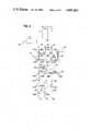
- FIG. 1is a front view of (partially in diagrammatic form) of a three channel analysis instrument in accordance with the invention
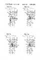
- FIG. 2is a diagram of the glucose channel portion of the flow network structure employed in the apparatus shown in FIG. 1;
- FIG. 3is a sectional view in part through the sample measuring chamber of the glucose channel, taken along the line 3--3, of FIG. 1;
- FIG. 4is a sectional view in part through the reagent measuring chamber of the urea channel taken along the line 4--4 of FIG. 1;
- FIGS. 5 and 6are a series of diagrammatic views of the sample distribution manifold in the flow network.
- FIG. 7is a series of diagrams showing an operational sequence of the apparatus shown in FIG. 1.
- FIG. 1Shown in FIG. 1 is a diagrammatic view of a three channel analysis instrument with photometric analysis cell 10 for glucose analysis, a similar photometric analysis cell 12 for urea analysis, and a third similar photometric analysis cell 14 for creatinine analysis, each cell 10, 12, 14 having associated radiation source and radiation sensor apparatus for photometric analysis.
- Analysis cells 10, 12 and 14are connected to sample inlet probe 16 by flow network structure 18 that includes an array of valves 20 of the type shown in Webster U.S. Pat. No. 4,304,257, the disclosure of which is specifically incorporated herein by reference, and that are operated by valve controller 21.
- Flow network structure 18also includes a 7.5 microliter volume sample measuring chamber 22 associated with the glucose channel; a 3.5 microliter volume sample measuring chamber 24 associated with the urea channel, sample measuring chambers 26, 28 (ten microliter and 3.5 microliter volume respectively) associated with the creatinine channel; glucose reagent measuring chamber 30 (300 microliter volume); urea reagent measuring chamber 32 (600 microliter volume); creatinine reagent measuring chamber 34 (300 microliter volume); vacuum manifolds 36, 38 and pump chamber structure 40.
- Flow network assembly 18has an inlet 42 from sample probe 16; inlet 44 connected to flush reservoir 46; inlet 48 connected to glucose reagent reservoir 50; inlet 52 connected to urea reagent reservoir 54; inlet 56 connected to tap 58 of sample probe 16; outlet 60 connected to vacuum chamber 62; inlet 64 connected to creatinine reagent reservoir 66; outlet 68 connected to vacuum chamber 70; outlet 72 connected to vacuum chamber 62; inlet 74 connected to the outlet of the flush preheater section 76 for the glucose channel; outlet 78 connected to the inlet 80 of glucose analysis cell 10; inlet 82 connected to the outlet 84 of glucose analysis cell 10; inlet 86 connected to the outlet of the flush preheater section 88 associated with the urea channel; outlet 90 connected to the inlet 92 of the urea analysis cell 12; inlet 94 connected to the outlet 96 of cell 12; outlet 98 connected to vacuum chamber 70; inlet 100 connected to the outlet of flush preheater section 102 associated with the creatinine channel; outlet 104 connected
- Flush reservoir 46is also connected to manifold 114 that has inlets to preheater sections 76, 80 and 102; vacuum pump 116 is connected to vacuum chamber 62 to establish a vacuum on the order of 22-24 inches of mercury in chamber 62; and the two chambers 70 and 62 are interconnected by regulator 118 so that a regulated vacuum of about fifteen inches of mercury is established in chamber 70.
- the flow network assembly 18includes a rectangular array of valves 20 with the valves spaced on centers of about 1.5 centimeters and arranged in five rows A-E and twelve columns A-L.
- valve 20ACthe valve connected to sample inlet port 42
- valve 20EAthe valve connected to inlet port 74
- valve 20EBthe valve connected to outlet port 78
- valve 20ABis of the "isolation" type and isolates through channel 120 (that extends between isolation valves 20AA and 20AC) from channel 122 that extends to pump chamber 40;
- valve 20BBis an isolation valve that isolates distribution manifold section 150G from the inlet 124G to glucose sample metering chamber 22;
- valve 20CBisolates the outlet 126G of sample metering chamber 22 from the chamber bypass channel 128G that extends from isolation valve 20BA to isolation valve 20DB;
- valve 20EBisolates the channel 130G (that extends from isolation valve 20DB through valves 20DA and 20EA to isolation valve 20EB) from channel 132G (that extends to outlet port 78).
- valve 20AGisolates channel 134U (connected to port 52) from channel 136U which is in direct communication with urea reagent metering chamber 32; valve 20BG isolates channel 136U from distribution manifold 150; valve 20CG isolates channel 138 (which extends from isolation valve 20DI to vacuum manifold 36) from channel 140 (which extends to vacuum manifold 38 and provides a bypass or short circuit network between vacuum manifolds 36 and 38 for use during cleaning and flushing); valve 20DG is of the "vent” type that isolates vent 142U from the channel 144 (which extends between urea reagent metering chamber 32 and isolation valve 20DH); and valve 20EG is another "vent” valve which vents the channel 146 that extends from isolation valve 20EH to inlet port 94.
- Flow network 18has three similar but distinct flow channel sections, one for glucose analysis, a second for urea analysis and a third for creatinine analysis.
- Each channelincludes a sample metering chamber and a reagent metering chamber of volume proportioned to the volume of the sample metering chamber so that the desired dilution is obtained.
- the creatinine analysis sectionhas two sample metering chambers 26 and 28 so that different dilution ratios may be employed as desired.
- chamber 26may be employed with a serum creatinine analysis while chamber 28 (a greater dilution ratio) may be employed with a urine creatinine analysis.
- the sample to be analyzedis flowed to the three analysis sections via distribution manifold 150--isolation valves 20BD and 20BH in distribution manifold 150 serving to separate channel sections 150G, 150U and 150C.
- Sample probe 16is connected via inlet port 42 and valves 20AC, 20AB and 20AA to sample distribution manifold 150 that has a cross-sectional area of about 0.3 square millimeter so that a length of about twenty-five centimeters is provided for a seventy microliter sample volume.
- the glucose section 150G of that distribution manifoldextends through valves 20BA, 20BB and 20CC to isolation valve 20BD; the urea section 150U extends through valves 20BE, 20BF and 20BG to isolation valve 20BH, and the creatinine section 150C extends through valves 20BI, 20BJ and 20BK, 20BL and 20AL to vacuum isolation valve 20AK.
- the three sample-reagent measuring and mixing networks that are connected to distribution manifold 150are of similar configuration, the measuring and mixing network for the glucose channel being shown in slightly larger scale in diagrammatic form in FIG. 2.
- the tip 148 of sample probe 16is inserted (by a drive motor--not shown) into a sample cup and with valve 20AC closed, distribution manifold 150 is connected to vacuum chamber 70 to reduce the pressure in that manifold channel.
- valve 20BDis then closed to seal the reduced pressure in distribution manifold 150G and when isolation valve 20AC is opened the sealed reduced pressure draws sample into the inlet probe towards distribution manifold 150.
- That valve sequence of alternate opening and closing valves 20AC and 20BDis repeated so that the volume of trapped reduced pressure between the leading edge of the sample and valve 20BD is progressively reduced until the leading edge of the sample is at valve 20BD in a self-limiting process--a seventy microliter volume of sample having been drawn into probe 16 and channels 120 and 150G.
- Sample probe 16is then withdrawn from the sample cup and the seventy microliter sample is positioned in the distribution manifold 150 by sequential and alternate opening and closing of valves 20AA, 20BD, 20BH and 20AK until the leading edge of the sample is at valve 20AK in the same self-limiting liquid movement process.
- the three metering chambers 22, 24 and 26are sequentially filled from manifold 150 while the corresponding reagent metering chambers 30, 32 and 34 are being concurrently filled from their respective reservoirs 50, 54 and 66. After those six metering chambers are filled, adjacent flow paths (including the distribution manifold 150) are flushed to remove excess material. Then the metered sample quantity and the corresponding metered reagent for each analysis channel are flowed in a mixing and dilution sequence into the corresponding analysis cell 10, 12, 14 (each of which has a volume about twice the volume of the reagent-sample mixture to be analyzed).
- Airis drawn through the diluted sample mixture in each analysis chamber in a bubbling action that provide further mixing and then the diluted mixture in each analysis chamber is subjected to reduced pressure for degassing. After an equilibration interval of about ten seconds, the three diluted samples are concurrently spectrophotometrically analyzed during which interval the flow network is flushed. After analysis, the analysis cells 10, 12 and 14 are emptied and cleaned in preparation for the next analysis sequence.
- That flow network arrayincludes transparent face plate 152 of cast acrylic resin. Clamped against the bottom surface of face plate 152 is manifold diaphragm sheet 154 of white polyurethane that has a smooth, pit-free surface. Apertured backing plate 156 is seated against diaphragm sheet 154 by mounting plate 158, and the stack of face plate 152, diaphragm 154, backing plate 156 and mounting plate 158 are secured together by resilient fasteners 160 (FIG. 1). Secured to diaphragm member 154 is an array of actuators 162, the head 164 of each being embedded in the polyurethane membrane sheet 154. A spring 166 seated between surface 168 of actuator 162 and surface 170 of mounting plate 158, maintaining membrane 154 in seated or valve closed position; and movement of actuator 162 away from face plate 152 opens the valve.
- the sectional view of FIG. 3is through glucose sample measuring chamber 22 and manifold 36 while the sectional view of FIG. 4 is through urea reagent measuring chamber 32 and manifold 38 as well as portions of the associated valves and interconnecting flow networks.
- Each of the reagent metering chambers 30, 32, 34is entirely bounded by acrylic plastic, a sheet 171 of plastic being solvent bonded to the upper surface of face plate 152 to define the outer wall of chamber 32, the other reagent measuring chambers 30 and 34 being similarly formed.
- FIG. 5shows in diagrammatic form an operating sequence of the valves connected between sample inlet 148 and vacuum chamber 70.
- valves AC, AA, BD, BH and AKare initially closed (FIG. 5a) and probe 16 is moved down by a stepping motor to insert its tip 148 into the sample cup.
- isolation valves AK, BH, BD and AAare opened (FIG. 5b) to allow the regulated vacuum from chamber 70 to reduce the pressure in distribution manifold 150 and inlet channel 120.
- isolation valve AKis closed (sealing that reduced pressure in channel 120 and manifold 150) and after a 1/10 second delay isolation valve AC is opened (FIG. 5c) so that the reduced pressure trapped by closed isolation valve AK draws sample 172 into probe 16 and towards valve BD. Isolation valve AC is then closed and isolation valve AK is opened to recharge manifold 150 with reduced pressure. After a delay of 1/10 of a second isolation valve BD is closed and isolation valve AC is opened (FIG. 5d) so that the reduced pressure trapped by closed isolation valve BD draws sample 172 further into probe 16 and past valve AC toward valve BD. After 1/10 of a second isolation valve AC is closed (clamping leading edge 174 of sample 172--FIG.
- isolation valve BDis again opened to charge channel 120 and section 150G of the distribution manifold between leading edge 174 and valve BD with reduced pressure (FIG. 5e). Isolation valve BD is then again closed and isolation valve AC opened after 1/10 of a second for about 1/4 of a second (releasing sample 172--FIG. 5f) so that the reduced pressure trapped between leading edge 174 and valve BD draws in the sample 172 further along the manifold 150G.
- the sequence of valve operations indicated in FIG. 5d-f when repeated four timesdraws in the sample 172 into probe 16 and positions its leading edge 174 at, but not beyond, valve BD (FIG. 5g) so that a seventy microliter volume of sample is drawn in to valve BD in a self-limiting process.
- valve AAWhen the leading edge 174 of sample 152 is at valve BD, valve AA is closed, as indicated in FIG. 5h, to "clamp" the sample 172 so that valves BD, BH and AK upstream from leading edge 174 may be opened to reduce the pressure in manifold sections 150U and 150C without movement of sample 172.
- Sample probe 16is then withdrawn and the seventy microliter sample 172 held in the sample probe 16 and connecting lines is positioned in distribution manifold 150 adjacent the three metering chambers 22, 24 and 26 (28) by a sequential operation of valves as indicated in FIG. 6.
- Valve AKis closed and then valves AA and BD are opened (FIG. 6a) to release sample 172 and allow the trapped reduced pressure to draw the sample towards valve AK.
- valve BHis closed (clamping sample 172 adjacent leading edge 174) and valve AK is opened to charge section 150C of the distribution manifold 150 between leading edge 174 and valve AK with reduced pressure.
- valve AKis closed (trapping the reduced pressure) and valve BH is opened (releasing sample 172) for about 1/4 second (FIG. 6c) so that the reduced pressure trapped between edge 174 and valve AK draws the sample 172 further along the manifold section 150C towards valve AK.
- Valve BHis then closed and valve AK opened to again apply reduced pressure to the sample leading edge 174 while the sample is restrained by closed valve BH.
- 6a-6dis repeated to supply progressively reduced trapped volumes of reduced pressure to further draw the sample 172 and position (in the self-limiting manner discussed above) the leading edge 174 at valve AK with the seventy microliter volume extending throughout the length of manifold 150 adjacent the three metering chambers 22, 24 and 26 (28) and the trailing edge 176 in channel section 120 as indicated in FIG. 6e.
- the rapid sequencing of the valves by controller 21 discussed abovepositions a metered seventy microliter volume of sample 172 accurately in distribution manifold 150 in a few seconds.
- the sample chambers 22, 24, 26 (or 28)are sequentially filled and the reagent metering chambers 30, 32 and 34 are concurrently filled from their respective reagent reservoirs 50, 54 and 66.
- FIG. 2A diagram of the glucose metering network is shown in FIG. 2, the urea and creatinine metering networks being similar.
- Glucose sample metering chamber 22is connected between isolation valves 20BB and 20CB while glucose reagent measuring chamber 30 is connected between isolation valves 20AF and 20DD.
- Connected between isolation valve 20DD and metering chamber 30is vent valve 20DC.
- a bypass channel 128Gparallels sample chamber 22 and extends from isolation valve 20BA to isolation valve 20DB.
- Three T valves 20BA, 20BB and 20BCare connected to the glucose section 150G of distribution manifold 150.
- T valve 20CBconnects the outlet 126G of sample metering chamber 22 to bypass channel 128G.
- a channel 130Gextends from isolation valve 20DB to isolation valve 20EB--channel 130G being connectable via T valve 20DA to vacuum manifold 36 and via T valve 20EA to flush preheater 76 (which preheater may be omitted if it is not necessary to thermally equilibrate the flush prior to introduction into the flow network).
- Vacuum manifold 38is connected by channel 148G to isolation valve 20DD, T valve 20ED connects channel 148G via channel 146G to the outlet of analysis cell 10 and valve 20EC vents channel 146G.
- the pumpincludes chamber 40 (similar to but of larger volume than valves 20), T valve 20AB and isolation valve 20AE, chamber 40 and valves 20AB and 20AE being operated in sequence as a positive displacement device that flows flush liquid through sample inlet line 120 and probe 16 for cleaning.
- Photometer cell 10has an inlet port 80 at its bottom and an outlet port 84 at its top that is connected to vacuum manifold 38 through isolation valve 20ED. As the volume of the reagent-sample mixture is less than that of photometer chamber 10, the reduced pressure used to draw the reagent sample mixture into the chamber without filling it also draws following air through the mixture for further mixing and then degassing. After analysis, the sample-reagent mixture is withdrawn through the inlet port 80 and isolation valves 20EB and 20DA to the vacuum manifold 36, the top port 84 of the analysis cell 10 being vented by vent valve 20EC during this sequence.
- FIG. 7ashows the sample 172 to be analyzed (symbolized by dark lines) held in distribution manifold 150 with its leading edge 174 blocked (at valve AK) and its trailing edge 176 exposed to atmosphere through open valve AC and sample probe 16.
- Valves DA, DB and CBare opened to apply negative pressure (symbolized by dots) from manifold 36 to reduce the pressure in sample metering chamber 22 and bypass channel 128G; and valve DD is opened to similarly reduce the pressure in reagent metering chamber 30.
- Valve CBis then closed and valve BB is opened so that the reduced pressure trapped in sample metering chamber 22 draws sample 172 into that chamber towards closed valve CB as indicated in FIG. 7b.
- isolation valve DDis closed, and then valve AF is opened so that the reduced pressure trapped in reagent metering chamber 30 draws reagent 178 (symbolized by slant lines) from reservoir 50 through valve AF into chamber 30.
- Valves DA and DBare then closed and valve CB opened so that the leading portion 180 of sample is drawn through metering chamber 22 into portions of the bypass channel 128G as indicated in FIG. 7c.
- Valves BB and CBare then closed, isolating the metered quantity 182 of sample 172 in chamber 22, as indicated in FIG. 7d, from leading portion 180 as well as from trailing portion 176.
- the other two sample metering chambers 24, 26 (28)are then similarly filled in sequence.
- the reagent metering chambers 30, 32 and 34are concurrently filled by alternately closing and opening valves DD and AF (and corresponding valves DH and AG and DL and AJ) to draw reagents 178G, U and C into the metering chambers 30, 32 and 34 respectively (valve DD being opened to recharge metering chamber 30 with reduced pressure while the reagent 178G is clamped by closed valve AF as indicated in FIG. 7c; then valve DD is closed to trap the reduced pressure in metering chamber 30 and line 144; and then valve AF is opened (as indicated in FIG.
- valves DD and AFand corresponding valves in each of the three reagent metering chamber flow paths fills the respective metering chambers up to but not beyond valves DD, DH and DL in self-limiting manner similar to the filling of manifold 150 described above in connection with FIGS. 5 and 6.
- valve AKis opened to draw the excess sample 172 from the distribution manifold 150, and then valves AE and AB are opened to draw flush solution 184 (symbolized by dashed lines) from reservoir 46 through distribution manifold 150 in flushing and cleaning action.
- Valves AA and ABare then closed and valves EA, DB and BA are opened to draw flush 184 through preheater 76 and then flow through valves EA, DA, DB, CB and BA into the distribution manifold 150 for flushing out the leading portions 180 of sample 172 that have been held in the bypass channel 128G (FIG. 7e).
- the urea and creatinine channelsare similarly flushed.
- Valve AHis also opened to connect the vacuum tap 58 (FIG. 1) of probe 16 to vacuum chamber 62 and chamber 40 and valves AB and AE of the pump array are operated in sequence to provide positive displacement pump action to draw flush solution 184 from reservoir 46 and to flow it in the reverse direction through probe 16 where the discharged flush solution 184 is drawn from probe tip 148 by tap 58 through valve AH to vacuum chamber 62.
- valve AEis opened and then the volume of pump chamber 40 is increased to draw flush solution into that chamber.
- Valve AEis then closed, valve AB opened and the pump chamber 40 is collapsed (membrane 154 is seated against face plate 152) to force the volume of liquid from chamber 40 out through valve AC and sample probe 16.
- valve AAis opened to vent the distribution manifold 150 and remove the flush solution.
- Reagent vent valve DC and isolation valve DDare opened and the excess reagent 178 in channel 144G is drawn into vacuum manifold 38 and then isolation valve DA is opened to draw flush solution 184 from the bypass channel 128G into manifold 36.
- Valves BA, DB and DAare pulsed to provide a pulsating liquid flow and enhanced cleaning action. Valves BA, DA and DB are then closed and valves AA, BH and BD are similarly pulsed to clean and air dry the distribution manifold 150. Those valves are then closed, isolating segments 150G, 150U and 150C of the distribution manifold associated with each analysis channel.
- vent valve DC and isolation valve BCare opened, connecting reagent measuring metering chamber 30 to the isolated segment 150G of distribution manifold 150; valve BA is opened, connecting that isolated segment 150G to bypass channel 128; and T valve ED is opened to apply reduced pressure from vacuum manifold 38 to analysis cell 10 for about 1/4 second. Valve ED is then closed, trapping the reduced pressure in cell 10 and in those portions of flow network 18 connected to cell inlet 80.
- valves EB and DBapplies that reduced pressure to the bypass channel 128G and the isolated segment 150G of distribution manifold 150 to draw reagent 178G from chamber 30 (vented by open vent valve DC) through open valve BC, distribution channel segment 150G and bypass channel 128G towards analysis cell 10.
- valve EBis closed and valve ED is opened to recharge the reduced pressure in the analysis cell.
- the sample chamber isolation valves BB and CBare also opened.
- isolation valve EDis again closed and isolation valve EB is opened so that the metered sample quantity 182 is drawn from chamber 22 followed by a flow of reagent 178 through sample chamber 22 (valve BA being closed during this interval).
- isolation valve CBis closed and valve BA is opened so that flow of reagent continues through the bypass channel 128G until the entire metered quantity of reagent 178 (together with the metered sample quantity 182) has been flowed into analysis cell 10, the reagent flow alternating between sample chamber 22 and bypass channel 128.
- valves EB and EDare alternately opened and closed to recharge the reduced pressure head in analysis chamber 10. Following air is bubbled through the mixture 186 (symbolized by alternating heavy and light slant lines) in analysis cell 10 from the open vent valve DC to provide further mixing and then vent valve DC is closed for debubbling of the diluted sample mixture 186 in analysis cell 10. Isolation valve EB is then closed (FIG. 7h) preparatory to photometric analysis.
- Vent valve ECis opened during photometric analysis to vent analysis cell 10.
- distribution manifold valves(AA, BD, BH and AK) are opened as are valves AE and AB to draw flush solution 184 through the distribution manifold 150; then valves BB, CB, DB and DA are opened to draw flush solution 184 through sample metering chamber 22 to vacuum manifold 36; then valve BA is opened to flow flush solution 184 through the bypass channel 128; then flush solution flow is then turned off and valve AC is opened to vent the lines to atmosphere, valves BB, CB, BA, DB being pulsed as air is flowed through them to clean and dry the lines in preparation for the next analysis sequence.
- valves EB and DAare opened to apply reduced pressure to the input 80 of analysis chamber 10 to draw the analyzed mixture 186 from that chamber for discharge through manifold 36 into vacuum chamber 62.
- Vent valve EC and isolation valve DAare then closed and valves EA and ED are opened to draw flush solution 184 through analysis chamber 10 and vacuum manifold 38 for discharge into vacuum chamber 62 in a cleaning of the analysis chamber.
- the analysis chamberis then vented and the valves EB and DA are pulsed and then turned off so that the channel is in condition for the next analysis cycle.
Landscapes
- Physics & Mathematics (AREA)
- Health & Medical Sciences (AREA)
- Life Sciences & Earth Sciences (AREA)
- Chemical & Material Sciences (AREA)
- Analytical Chemistry (AREA)
- Biochemistry (AREA)
- General Health & Medical Sciences (AREA)
- General Physics & Mathematics (AREA)
- Immunology (AREA)
- Pathology (AREA)
- Automatic Analysis And Handling Materials Therefor (AREA)
- Investigating Or Analysing Biological Materials (AREA)
- Sampling And Sample Adjustment (AREA)
Abstract
Description
Claims (36)
Priority Applications (7)
| Application Number | Priority Date | Filing Date | Title |
|---|---|---|---|
| US06/667,299US4601881A (en) | 1984-11-01 | 1984-11-01 | Liquid handling system |
| EP85112666AEP0180064B1 (en) | 1984-11-01 | 1985-10-07 | Liquid handling system |
| DE8585112666TDE3583206D1 (en) | 1984-11-01 | 1985-10-07 | DEVICE FOR MANIPULATING LIQUIDS. |
| EP90120207AEP0420296A1 (en) | 1984-11-01 | 1985-10-07 | Liquid handling system |
| AU48459/85AAU4845985A (en) | 1984-11-01 | 1985-10-10 | Flow network liquid analysis system |
| CA000494344ACA1260290A (en) | 1984-11-01 | 1985-10-31 | Liquid handling system |
| JP60246106AJPS61110028A (en) | 1984-11-01 | 1985-11-01 | liquid handling system |
Applications Claiming Priority (1)
| Application Number | Priority Date | Filing Date | Title |
|---|---|---|---|
| US06/667,299US4601881A (en) | 1984-11-01 | 1984-11-01 | Liquid handling system |
Publications (1)
| Publication Number | Publication Date |
|---|---|
| US4601881Atrue US4601881A (en) | 1986-07-22 |
Family
ID=24677655
Family Applications (1)
| Application Number | Title | Priority Date | Filing Date |
|---|---|---|---|
| US06/667,299Expired - Fee RelatedUS4601881A (en) | 1984-11-01 | 1984-11-01 | Liquid handling system |
Country Status (6)
| Country | Link |
|---|---|
| US (1) | US4601881A (en) |
| EP (2) | EP0180064B1 (en) |
| JP (1) | JPS61110028A (en) |
| AU (1) | AU4845985A (en) |
| CA (1) | CA1260290A (en) |
| DE (1) | DE3583206D1 (en) |
Cited By (28)
| Publication number | Priority date | Publication date | Assignee | Title |
|---|---|---|---|---|
| US4844870A (en)* | 1987-07-17 | 1989-07-04 | Fisher Scientific Company | Liquid monitoring |
| US4844872A (en)* | 1987-07-17 | 1989-07-04 | Fisher Scientific Company | Fluid handling |
| US4859422A (en)* | 1987-07-17 | 1989-08-22 | Fisher Scientific Company | Analysis system |
| US4906432A (en)* | 1987-07-17 | 1990-03-06 | Fisher Scientific Company | Liquid handling |
| US5088515A (en)* | 1989-05-01 | 1992-02-18 | Kamen Dean L | Valve system with removable fluid interface |
| EP0492309A1 (en)* | 1990-12-21 | 1992-07-01 | Millipore Corporation | Fluid delivery system |
| US5542444A (en)* | 1994-11-07 | 1996-08-06 | Abbott Laboratories | Valve and method of using |
| US5743295A (en)* | 1995-07-20 | 1998-04-28 | Abbott Laboratories | Valve construction and method of use |
| US5775371A (en)* | 1995-03-08 | 1998-07-07 | Abbott Laboratories | Valve control |
| US5834314A (en)* | 1994-11-07 | 1998-11-10 | Abbott Laboratories | Method and apparatus for metering a fluid |
| US5846396A (en)* | 1994-11-10 | 1998-12-08 | Sarnoff Corporation | Liquid distribution system |
| US5849598A (en)* | 1996-03-15 | 1998-12-15 | Washington University | Method for transferring micro quantities of liquid samples to discrete locations |
| US5967163A (en)* | 1996-01-30 | 1999-10-19 | Abbott Laboratories | Actuator and method |
| US5980704A (en)* | 1995-06-07 | 1999-11-09 | David Sarnoff Research Center Inc. | Method and system for inhibiting cross-contamination in fluids of combinatorial chemistry device |
| US5992820A (en)* | 1997-11-19 | 1999-11-30 | Sarnoff Corporation | Flow control in microfluidics devices by controlled bubble formation |
| US6033544A (en)* | 1996-10-11 | 2000-03-07 | Sarnoff Corporation | Liquid distribution system |
| US6117396A (en)* | 1998-02-18 | 2000-09-12 | Orchid Biocomputer, Inc. | Device for delivering defined volumes |
| US6485690B1 (en) | 1999-05-27 | 2002-11-26 | Orchid Biosciences, Inc. | Multiple fluid sample processor and system |
| EP0669533B1 (en)* | 1994-02-23 | 2002-12-04 | Compagnie Generale Des Matieres Nucleaires | Automatic analyser with fixed containers |
| US20040121450A1 (en)* | 2002-12-19 | 2004-06-24 | Pugia Michael J. | Method and apparatus for splitting of specimens into multiple channels of a microfluidic device |
| US20040126538A1 (en)* | 2002-01-18 | 2004-07-01 | Corcoran Craig S. | Sheet having microsized architecture |
| US20080130402A1 (en)* | 2006-11-22 | 2008-06-05 | Hideyuki Karaki | Microchannel chip and converging device |
| US20110032513A1 (en)* | 2006-10-13 | 2011-02-10 | Mathieu Joanicot | Fluid flow device, assembly for determining at least one characteristic of a physico-chemical system therewith |
| US9033307B2 (en) | 2009-05-29 | 2015-05-19 | Boehringer Ingelheim Vetmedica Gmbh | Valve for lab-on-a-chip systems, method for actuating and for producing valve |
| US9151409B2 (en) | 2009-05-29 | 2015-10-06 | Boehringer Ingelheim Vetmedica Gmbh | Device and method for controlling fluid flows in lab-on-a-chip systems and method for producing device |
| EP3263218A1 (en)* | 2016-06-27 | 2018-01-03 | M2p-labs GmbH | Microfluidic chip comprising a functional area covered with a flexible or deformable lid, and microfluidic system |
| CN111948409A (en)* | 2019-05-15 | 2020-11-17 | 深圳市理邦精密仪器股份有限公司 | Microfluidic test card, test card assembly, equipment and control method |
| US20210123936A1 (en)* | 2018-07-10 | 2021-04-29 | Precision Planting Llc | Agricultural sampling system and related methods |
Families Citing this family (22)
| Publication number | Priority date | Publication date | Assignee | Title |
|---|---|---|---|---|
| US4624928A (en)* | 1984-11-01 | 1986-11-25 | Allied Corporation | Liquid handling process |
| US6300138B1 (en)* | 1997-08-01 | 2001-10-09 | Qualigen, Inc. | Methods for conducting tests |
| US6117290A (en)* | 1997-09-26 | 2000-09-12 | Pepex Biomedical, Llc | System and method for measuring a bioanalyte such as lactate |
| DE19758356A1 (en)* | 1997-12-22 | 1999-07-08 | Ufz Leipzighalle Gmbh | Modular multi-channel sampling and measuring system for automatic long-term analysis of fluids for hydrogeological field and laboratory tests |
| US6464849B1 (en) | 1999-10-07 | 2002-10-15 | Pepex Biomedical, L.L.C. | Sensor for measuring a bioanalyte such as lactate |
| EP1111281A1 (en)* | 1999-12-23 | 2001-06-27 | Scitec Research SA | Analyzer comprising a miniaturised flow plate |
| DE10024992C2 (en)* | 2000-05-22 | 2002-09-19 | Forschungszentrum Juelich Gmbh | Method and device for determining substrate and product concentrations in a medium |
| US6662091B2 (en) | 2001-06-29 | 2003-12-09 | Battelle Memorial Institute | Diagnostics/prognostics using wireless links |
| US6889165B2 (en) | 2001-07-02 | 2005-05-03 | Battelle Memorial Institute | Application specific intelligent microsensors |
| WO2007044938A2 (en)* | 2005-10-13 | 2007-04-19 | The Regents Of The University Of California | Microfluidic samplers and methods for making and using them |
| US9044178B2 (en) | 2007-08-30 | 2015-06-02 | Pepex Biomedical, Llc | Electrochemical sensor and method for manufacturing |
| US8702932B2 (en) | 2007-08-30 | 2014-04-22 | Pepex Biomedical, Inc. | Electrochemical sensor and method for manufacturing |
| WO2010056878A2 (en) | 2008-11-14 | 2010-05-20 | Pepex Biomedical, Llc | Electrochemical sensor module |
| US8951377B2 (en) | 2008-11-14 | 2015-02-10 | Pepex Biomedical, Inc. | Manufacturing electrochemical sensor module |
| US8506740B2 (en) | 2008-11-14 | 2013-08-13 | Pepex Biomedical, Llc | Manufacturing electrochemical sensor module |
| US9585605B2 (en) | 2011-05-19 | 2017-03-07 | Pepex Biomedical, Inc. | Fluid management and patient monitoring system |
| US9504162B2 (en) | 2011-05-20 | 2016-11-22 | Pepex Biomedical, Inc. | Manufacturing electrochemical sensor modules |
| GB201115895D0 (en) | 2011-09-14 | 2011-10-26 | Embl | Microfluidic device |
| EP2925229A4 (en) | 2012-12-03 | 2017-01-25 | Pepex Biomedical, Inc. | Sensor module and method of using a sensor module |
| WO2015187959A1 (en) | 2014-06-04 | 2015-12-10 | Pepex Biomedical, Inc. | Electrochemical sensors and methods for making electrochemical sensors using advanced printing technology |
| EP3391957B1 (en)* | 2015-12-14 | 2021-10-13 | Saraya Co., Ltd. | Liquid supplying system and method for driving same |
| KR20210107771A (en)* | 2018-12-27 | 2021-09-01 | 가부시키가이샤 호리바 세이사꾸쇼 | Fluid metering device and sample analysis device having same |
Citations (10)
| Publication number | Priority date | Publication date | Assignee | Title |
|---|---|---|---|---|
| US3609040A (en)* | 1969-02-24 | 1971-09-28 | Lilly Co Eli | Automated system for performing sample measurements, dilutions and photometric measurements |
| US3613729A (en)* | 1970-02-16 | 1971-10-19 | Packard Instrument Co Inc | Valve system |
| US3900289A (en)* | 1971-04-12 | 1975-08-19 | Abbott Lab | Apparatus and method for filling a compartment |
| US3934611A (en)* | 1972-08-04 | 1976-01-27 | Jean Gachot | Comparator for coded signals represented by a pressure of fluid |
| US3951167A (en)* | 1974-12-05 | 1976-04-20 | E. I. Du Pont De Nemours And Company | Fluid handling assembly |
| US3963440A (en)* | 1974-06-27 | 1976-06-15 | Instrumentation Laboratory, Inc. | Analysis system |
| US4108602A (en)* | 1976-10-20 | 1978-08-22 | Hanson Research Corporation | Sample changing chemical analysis method and apparatus |
| US4168294A (en)* | 1977-02-14 | 1979-09-18 | Claudio Calzi | Instrument for photometric analyses |
| US4219530A (en)* | 1978-01-27 | 1980-08-26 | Brinkmann Instruments, Inc. | Apparatus for analyzing biological specimens |
| US4304257A (en)* | 1980-07-01 | 1981-12-08 | Instrumentation Laboratory Inc. | Valve with flexible sheet member |
Family Cites Families (3)
| Publication number | Priority date | Publication date | Assignee | Title |
|---|---|---|---|---|
| GB2019995B (en)* | 1978-04-10 | 1982-09-29 | Kaartinen N | Method and apparatus for handling batches of liquids |
| US4283262A (en)* | 1980-07-01 | 1981-08-11 | Instrumentation Laboratory Inc. | Analysis system |
| US4624928A (en)* | 1984-11-01 | 1986-11-25 | Allied Corporation | Liquid handling process |
- 1984
- 1984-11-01USUS06/667,299patent/US4601881A/ennot_activeExpired - Fee Related
- 1985
- 1985-10-07EPEP85112666Apatent/EP0180064B1/ennot_activeExpired
- 1985-10-07EPEP90120207Apatent/EP0420296A1/ennot_activeWithdrawn
- 1985-10-07DEDE8585112666Tpatent/DE3583206D1/ennot_activeExpired - Fee Related
- 1985-10-10AUAU48459/85Apatent/AU4845985A/ennot_activeAbandoned
- 1985-10-31CACA000494344Apatent/CA1260290A/ennot_activeExpired
- 1985-11-01JPJP60246106Apatent/JPS61110028A/enactiveGranted
Patent Citations (10)
| Publication number | Priority date | Publication date | Assignee | Title |
|---|---|---|---|---|
| US3609040A (en)* | 1969-02-24 | 1971-09-28 | Lilly Co Eli | Automated system for performing sample measurements, dilutions and photometric measurements |
| US3613729A (en)* | 1970-02-16 | 1971-10-19 | Packard Instrument Co Inc | Valve system |
| US3900289A (en)* | 1971-04-12 | 1975-08-19 | Abbott Lab | Apparatus and method for filling a compartment |
| US3934611A (en)* | 1972-08-04 | 1976-01-27 | Jean Gachot | Comparator for coded signals represented by a pressure of fluid |
| US3963440A (en)* | 1974-06-27 | 1976-06-15 | Instrumentation Laboratory, Inc. | Analysis system |
| US3951167A (en)* | 1974-12-05 | 1976-04-20 | E. I. Du Pont De Nemours And Company | Fluid handling assembly |
| US4108602A (en)* | 1976-10-20 | 1978-08-22 | Hanson Research Corporation | Sample changing chemical analysis method and apparatus |
| US4168294A (en)* | 1977-02-14 | 1979-09-18 | Claudio Calzi | Instrument for photometric analyses |
| US4219530A (en)* | 1978-01-27 | 1980-08-26 | Brinkmann Instruments, Inc. | Apparatus for analyzing biological specimens |
| US4304257A (en)* | 1980-07-01 | 1981-12-08 | Instrumentation Laboratory Inc. | Valve with flexible sheet member |
Cited By (41)
| Publication number | Priority date | Publication date | Assignee | Title |
|---|---|---|---|---|
| US4844872A (en)* | 1987-07-17 | 1989-07-04 | Fisher Scientific Company | Fluid handling |
| US4859422A (en)* | 1987-07-17 | 1989-08-22 | Fisher Scientific Company | Analysis system |
| US4906432A (en)* | 1987-07-17 | 1990-03-06 | Fisher Scientific Company | Liquid handling |
| EP0299658A3 (en)* | 1987-07-17 | 1990-05-16 | INSTRUMENTATION LABORATORY S.p.A. | Analysis system |
| EP0299659A3 (en)* | 1987-07-17 | 1990-08-22 | INSTRUMENTATION LABORATORY S.p.A. | Liquid handling |
| AU602469B2 (en)* | 1987-07-17 | 1990-10-11 | Il Holding S.P.A. | Liquid handling |
| US4844870A (en)* | 1987-07-17 | 1989-07-04 | Fisher Scientific Company | Liquid monitoring |
| US5088515A (en)* | 1989-05-01 | 1992-02-18 | Kamen Dean L | Valve system with removable fluid interface |
| EP0492309A1 (en)* | 1990-12-21 | 1992-07-01 | Millipore Corporation | Fluid delivery system |
| EP0669533B1 (en)* | 1994-02-23 | 2002-12-04 | Compagnie Generale Des Matieres Nucleaires | Automatic analyser with fixed containers |
| US5834314A (en)* | 1994-11-07 | 1998-11-10 | Abbott Laboratories | Method and apparatus for metering a fluid |
| US5542444A (en)* | 1994-11-07 | 1996-08-06 | Abbott Laboratories | Valve and method of using |
| US5846396A (en)* | 1994-11-10 | 1998-12-08 | Sarnoff Corporation | Liquid distribution system |
| US5794641A (en)* | 1995-03-08 | 1998-08-18 | Abbott Laboratories | Valve control |
| US5791375A (en)* | 1995-03-08 | 1998-08-11 | Abbott Laboratories | Valve control |
| US5775371A (en)* | 1995-03-08 | 1998-07-07 | Abbott Laboratories | Valve control |
| US6331439B1 (en) | 1995-06-07 | 2001-12-18 | Orchid Biosciences, Inc. | Device for selective distribution of liquids |
| US5980704A (en)* | 1995-06-07 | 1999-11-09 | David Sarnoff Research Center Inc. | Method and system for inhibiting cross-contamination in fluids of combinatorial chemistry device |
| US5743295A (en)* | 1995-07-20 | 1998-04-28 | Abbott Laboratories | Valve construction and method of use |
| US5967163A (en)* | 1996-01-30 | 1999-10-19 | Abbott Laboratories | Actuator and method |
| US5849598A (en)* | 1996-03-15 | 1998-12-15 | Washington University | Method for transferring micro quantities of liquid samples to discrete locations |
| US6033544A (en)* | 1996-10-11 | 2000-03-07 | Sarnoff Corporation | Liquid distribution system |
| US5992820A (en)* | 1997-11-19 | 1999-11-30 | Sarnoff Corporation | Flow control in microfluidics devices by controlled bubble formation |
| US6117396A (en)* | 1998-02-18 | 2000-09-12 | Orchid Biocomputer, Inc. | Device for delivering defined volumes |
| US6485690B1 (en) | 1999-05-27 | 2002-11-26 | Orchid Biosciences, Inc. | Multiple fluid sample processor and system |
| US20040126538A1 (en)* | 2002-01-18 | 2004-07-01 | Corcoran Craig S. | Sheet having microsized architecture |
| US20040121450A1 (en)* | 2002-12-19 | 2004-06-24 | Pugia Michael J. | Method and apparatus for splitting of specimens into multiple channels of a microfluidic device |
| US7125711B2 (en)* | 2002-12-19 | 2006-10-24 | Bayer Healthcare Llc | Method and apparatus for splitting of specimens into multiple channels of a microfluidic device |
| US8420397B2 (en)* | 2006-10-13 | 2013-04-16 | Rhodia Operations | Fluid flow device and assembly employing a temperature gadient for determining at least one characteristic of a physico-chemical system therewith |
| US20110032513A1 (en)* | 2006-10-13 | 2011-02-10 | Mathieu Joanicot | Fluid flow device, assembly for determining at least one characteristic of a physico-chemical system therewith |
| US20080130402A1 (en)* | 2006-11-22 | 2008-06-05 | Hideyuki Karaki | Microchannel chip and converging device |
| US9033307B2 (en) | 2009-05-29 | 2015-05-19 | Boehringer Ingelheim Vetmedica Gmbh | Valve for lab-on-a-chip systems, method for actuating and for producing valve |
| US9151409B2 (en) | 2009-05-29 | 2015-10-06 | Boehringer Ingelheim Vetmedica Gmbh | Device and method for controlling fluid flows in lab-on-a-chip systems and method for producing device |
| US9709179B2 (en) | 2009-05-29 | 2017-07-18 | Boehringer Ingelheim Vetmedica Gmbh | Device for controlling fluid flows in lab-on-a-chip systems |
| EP3263218A1 (en)* | 2016-06-27 | 2018-01-03 | M2p-labs GmbH | Microfluidic chip comprising a functional area covered with a flexible or deformable lid, and microfluidic system |
| US20210123936A1 (en)* | 2018-07-10 | 2021-04-29 | Precision Planting Llc | Agricultural sampling system and related methods |
| US12000853B2 (en)* | 2018-07-10 | 2024-06-04 | Precision Planting Llc | Agricultural sampling, sample preparation and analysis system and related methods |
| US12055557B2 (en) | 2018-07-10 | 2024-08-06 | Precision Planting Llc | Agricultural sampling system and related methods |
| CN118706574A (en)* | 2018-07-10 | 2024-09-27 | 精密种植有限责任公司 | Agricultural sampling systems and related methods |
| CN111948409A (en)* | 2019-05-15 | 2020-11-17 | 深圳市理邦精密仪器股份有限公司 | Microfluidic test card, test card assembly, equipment and control method |
| CN111948409B (en)* | 2019-05-15 | 2024-05-14 | 深圳市理邦精密仪器股份有限公司 | Microfluidic test card, test card assembly, device and control method |
Also Published As
| Publication number | Publication date |
|---|---|
| CA1260290A (en) | 1989-09-26 |
| AU4845985A (en) | 1986-05-08 |
| EP0180064A3 (en) | 1987-12-09 |
| JPS61110028A (en) | 1986-05-28 |
| EP0420296A1 (en) | 1991-04-03 |
| DE3583206D1 (en) | 1991-07-18 |
| JPH0418269B2 (en) | 1992-03-27 |
| EP0180064B1 (en) | 1991-06-12 |
| EP0180064A2 (en) | 1986-05-07 |
Similar Documents
| Publication | Publication Date | Title |
|---|---|---|
| US4601881A (en) | Liquid handling system | |
| US4624928A (en) | Liquid handling process | |
| US4806316A (en) | Disposable device for use in chemical, immunochemical and microorganism analysis | |
| US7125711B2 (en) | Method and apparatus for splitting of specimens into multiple channels of a microfluidic device | |
| US12186745B2 (en) | Fluidic system for taking in, dispensing and moving liquids, method for processing fluids in a fluidic system | |
| US9157903B2 (en) | Microfluidic separation of plasma for colormetric assay | |
| US11975324B2 (en) | Microfluidic chip | |
| EP0299659A2 (en) | Liquid handling | |
| US4847208A (en) | Apparatus for immunohistochemical staining and method of rinsing a plurality of slides | |
| US4680270A (en) | Method and apparatus for conducting flow analysis | |
| US6942836B2 (en) | System for filling substrate chambers with liquid | |
| US5227290A (en) | Method for conducting diagnostic assays | |
| EP2952907A1 (en) | Cartridge for use in biochemistry, and set of cartridge for use in biochemistry and cartridge holder | |
| EP4141094A1 (en) | Liquid spreading device, liquid spreading method, liquid spreading system, combination device, and liquid passage device | |
| EP0299658A2 (en) | Analysis system | |
| AU593505B2 (en) | Fluid handling | |
| KR102833745B1 (en) | Microfluidic sample preparation device providing high repeatability | |
| EP0616555A1 (en) | Assay cartridge | |
| RU233867U1 (en) | Microfluidic reaction cartridge for automated enzyme immunoassay | |
| EP1483589B1 (en) | Device and method for automatically analysing the constituents of an analyte |
Legal Events
| Date | Code | Title | Description |
|---|---|---|---|
| AS | Assignment | Owner name:ALLIED CORPORATION, COLUMBIA ROAD AND PARK AVENUE, Free format text:ASSIGNMENT OF ASSIGNORS INTEREST.;ASSIGNOR:WEBSTER, MILO E.;REEL/FRAME:004332/0242 Effective date:19841030 | |
| AS | Assignment | Owner name:FISHER SCIENTIFIC COMPANY A CORP OF DE Free format text:ASSIGNMENT OF ASSIGNORS INTEREST.;ASSIGNOR:ALLIED CORPORATION A NY CORP;REEL/FRAME:004634/0501 Effective date:19860815 | |
| FEPP | Fee payment procedure | Free format text:PAYOR NUMBER ASSIGNED (ORIGINAL EVENT CODE: ASPN); ENTITY STATUS OF PATENT OWNER: LARGE ENTITY | |
| FPAY | Fee payment | Year of fee payment:4 | |
| FEPP | Fee payment procedure | Free format text:PAYER NUMBER DE-ASSIGNED (ORIGINAL EVENT CODE: RMPN); ENTITY STATUS OF PATENT OWNER: LARGE ENTITY Free format text:PAYOR NUMBER ASSIGNED (ORIGINAL EVENT CODE: ASPN); ENTITY STATUS OF PATENT OWNER: LARGE ENTITY | |
| AS | Assignment | Owner name:INIZIATIVE MARITTIME 1991, S.R.L., A CORPORATION Free format text:ASSIGNMENT OF ASSIGNORS INTEREST.;ASSIGNOR:FISHER SCIENTIFIC COMPANY, A CORP. OF DE;REEL/FRAME:005891/0407 Effective date:19911023 | |
| AS | Assignment | Owner name:CITIBANK N.A. Free format text:SECURITY INTEREST;ASSIGNOR:INIZIATIVE MARITTIME 1991, S.R.L.;REEL/FRAME:005913/0325 Effective date:19911023 | |
| AS | Assignment | Owner name:IL HOLDING S.P.A. Free format text:CHANGE OF NAME;ASSIGNOR:INIZIATIVE MARITTIME 1991 S.R.L.;REEL/FRAME:006179/0983 Effective date:19920219 | |
| REMI | Maintenance fee reminder mailed | ||
| LAPS | Lapse for failure to pay maintenance fees | ||
| FP | Lapsed due to failure to pay maintenance fee | Effective date:19940727 | |
| STCH | Information on status: patent discontinuation | Free format text:PATENT EXPIRED DUE TO NONPAYMENT OF MAINTENANCE FEES UNDER 37 CFR 1.362 |