US4601724A - Manufacture of tubing assembly for drainage catheter - Google Patents
Manufacture of tubing assembly for drainage catheterDownload PDFInfo
- Publication number
- US4601724A US4601724AUS06/614,633US61463384AUS4601724AUS 4601724 AUS4601724 AUS 4601724AUS 61463384 AUS61463384 AUS 61463384AUS 4601724 AUS4601724 AUS 4601724A
- Authority
- US
- United States
- Prior art keywords
- tubing
- length
- elastomeric
- elastomeric tubing
- ion
- Prior art date
- Legal status (The legal status is an assumption and is not a legal conclusion. Google has not performed a legal analysis and makes no representation as to the accuracy of the status listed.)
- Expired - Fee Related
Links
- 238000004519manufacturing processMethods0.000titleclaimsdescription5
- 239000000853adhesiveSubstances0.000claimsabstractdescription32
- 230000001070adhesive effectEffects0.000claimsabstractdescription32
- 238000000034methodMethods0.000claimsabstractdescription23
- 230000002861ventricularEffects0.000claimsabstractdescription20
- 238000007917intracranial administrationMethods0.000claimsabstractdescription9
- 230000002040relaxant effectEffects0.000claimsabstract5
- 210000001175cerebrospinal fluidAnatomy0.000claimsdescription16
- 238000004544sputter depositionMethods0.000claimsdescription12
- 229920002313fluoropolymerPolymers0.000claimsdescription9
- 238000012544monitoring processMethods0.000claimsdescription9
- 239000004811fluoropolymerSubstances0.000claimsdescription8
- 229920002379silicone rubberPolymers0.000claimsdescription8
- 239000004945silicone rubberSubstances0.000claimsdescription8
- 238000010884ion-beam techniqueMethods0.000claimsdescription6
- 210000001519tissueAnatomy0.000claimsdescription6
- 239000012530fluidSubstances0.000claimsdescription5
- XKRFYHLGVUSROY-UHFFFAOYSA-NArgonChemical compound[Ar]XKRFYHLGVUSROY-UHFFFAOYSA-N0.000claimsdescription4
- 239000007789gasSubstances0.000claimsdescription4
- 238000005259measurementMethods0.000claimsdescription3
- 229910052786argonInorganic materials0.000claimsdescription2
- 208000003906hydrocephalusDiseases0.000claimsdescription2
- 238000005304joiningMethods0.000claimsdescription2
- 230000000712assemblyEffects0.000abstractdescription4
- 238000000429assemblyMethods0.000abstractdescription4
- 239000000463materialSubstances0.000description11
- 239000011324beadSubstances0.000description6
- 230000015572biosynthetic processEffects0.000description6
- 210000004556brainAnatomy0.000description6
- 238000002513implantationMethods0.000description4
- 210000004027cellAnatomy0.000description2
- 239000012634fragmentSubstances0.000description2
- 102000004169proteins and genesHuman genes0.000description2
- 108090000623proteins and genesProteins0.000description2
- 230000000472traumatic effectEffects0.000description2
- ZAMOUSCENKQFHK-UHFFFAOYSA-NChlorine atomChemical compound[Cl]ZAMOUSCENKQFHK-UHFFFAOYSA-N0.000description1
- 239000004812Fluorinated ethylene propyleneSubstances0.000description1
- PXGOKWXKJXAPGV-UHFFFAOYSA-NFluorineChemical compoundFFPXGOKWXKJXAPGV-UHFFFAOYSA-N0.000description1
- 208000032843HemorrhageDiseases0.000description1
- 239000004944Liquid Silicone RubberSubstances0.000description1
- 239000004809TeflonSubstances0.000description1
- 229920006362Teflon®Polymers0.000description1
- 210000005013brain tissueAnatomy0.000description1
- 230000001413cellular effectEffects0.000description1
- 229910052801chlorineInorganic materials0.000description1
- 239000000460chlorineSubstances0.000description1
- 210000003161choroidAnatomy0.000description1
- 238000004891communicationMethods0.000description1
- 238000010276constructionMethods0.000description1
- 238000006073displacement reactionMethods0.000description1
- 229910052731fluorineInorganic materials0.000description1
- 239000011737fluorineSubstances0.000description1
- 238000001727in vivoMethods0.000description1
- 239000007924injectionSubstances0.000description1
- 238000002347injectionMethods0.000description1
- 229920002529medical grade siliconePolymers0.000description1
- 238000012806monitoring deviceMethods0.000description1
- 229920009441perflouroethylene propylenePolymers0.000description1
- 210000003200peritoneal cavityAnatomy0.000description1
- 229920001296polysiloxanePolymers0.000description1
- -1polytetrafluoroethylenePolymers0.000description1
- 229920001343polytetrafluoroethylenePolymers0.000description1
- 239000004810polytetrafluoroethyleneSubstances0.000description1
- 238000002360preparation methodMethods0.000description1
- 229920005989resinPolymers0.000description1
- 239000011347resinSubstances0.000description1
- 210000005245right atriumAnatomy0.000description1
- 210000004761scalpAnatomy0.000description1
- 238000004513sizingMethods0.000description1
- 238000007920subcutaneous administrationMethods0.000description1
- 210000003462veinAnatomy0.000description1
Images

Classifications
- A—HUMAN NECESSITIES
- A61—MEDICAL OR VETERINARY SCIENCE; HYGIENE
- A61M—DEVICES FOR INTRODUCING MEDIA INTO, OR ONTO, THE BODY; DEVICES FOR TRANSDUCING BODY MEDIA OR FOR TAKING MEDIA FROM THE BODY; DEVICES FOR PRODUCING OR ENDING SLEEP OR STUPOR
- A61M1/00—Suction or pumping devices for medical purposes; Devices for carrying-off, for treatment of, or for carrying-over, body-liquids; Drainage systems
- A61M1/84—Drainage tubes; Aspiration tips
- A—HUMAN NECESSITIES
- A61—MEDICAL OR VETERINARY SCIENCE; HYGIENE
- A61M—DEVICES FOR INTRODUCING MEDIA INTO, OR ONTO, THE BODY; DEVICES FOR TRANSDUCING BODY MEDIA OR FOR TAKING MEDIA FROM THE BODY; DEVICES FOR PRODUCING OR ENDING SLEEP OR STUPOR
- A61M27/00—Drainage appliance for wounds or the like, i.e. wound drains, implanted drains
- A61M27/002—Implant devices for drainage of body fluids from one part of the body to another
- A61M27/006—Cerebrospinal drainage; Accessories therefor, e.g. valves
Definitions
- This inventiongenerally relates to the making of tubing assemblies for catheters, more particularly to providing drainage catheters having extremely fine drainage inlets within a catheter tube that is flexible substantially throughout its length.
- the extremely fine drainage inletsare ion sputtered into a relatively short tubing length which is stretchably affixed over a longer length of flexible tubing, such tubing assemblies being particularly suitable for ventricular catheters to gain access to and drain cerebrospinal fluid from a ventricle of the brain.
- the more permanent types of these systemsoften include an implantable valve for allowing the passage of cerebrospinal fluid from a ventricle of the brain to a suitable drainage location in the body.
- implantable valvesare actuatable by displacement of a diaphragm or the like therewithin in response to applied pressure differentials in order to regulate passage of cerebrospinal fluid from the ventricular spaces through a ventricular catheter and on to the drainage location.
- Similar types of ventricular cathetersare included in temporarily implanted intracranial drainage, monitoring and/or injections systems which gain access to the ventricular spaces through a flexible ventricular catheter.
- ventricular catheterIn these types of systems, flexibility of the ventricular catheter is important due to the delicate brain tissue within which it comes into contact. Additionally, it is important that the catheter orifices through which fluid flows should be extremely fine, preferably so small as to retard blockage thereof. It was heretofore known that a substantial decrease in high incidence of inlet blockage caused by the ingrowth of the choroid plexas, ventricular collapse over the catheter orifices, or hemorrhage, cellular and fibran debris, can be successfully controlled by forming the catheter orifices by ion sputtering techniques.
- ion sputteringis particularly suitable for the formation of micro orifices within a relatively rigid material such as a fluoropolymer. Because of their rigidity, fluoropolymers are not well-suited for providing a single-stemmed catheter having a diameter that is typically required to achieve adequate flow therethrough in a ventricular catheter system.
- fluoropolymersare not well-suited for providing a single-stemmed catheter having a diameter that is typically required to achieve adequate flow therethrough in a ventricular catheter system.
- it has not been possible to provide a traditionally sized and shaped ventricular catheter having ion sputtered orificeswhich still possesses the flexibility that is extremely important for these types of catheters.
- the method and product produced therebyincludes providing a length of elastomeric tubing having radially directed openings therethrough, ion sputtering radially directed orifices through a length of tubing that is substantially shorter than the elastomeric tubing, and inserting the shorter length of tubing over the elastomeric tubing length, typically in association with stretching the elastomeric tubing in order to thereby decrease its average diameter when extended.
- adhesiveis applied along the edges of the shorter length of ion sputtered tubing, the elastomeric tubing being in a stretched condition, after which the elastomeric tubing is relaxed in order to encourage the adhesive to flow between and thus seal together the ion sputtered length of tubing and the length of elastomeric tubing.
- Another object of this inventionis to provide an improved method for manufacturing a tubular shaft having ion sputtered micro orifices while still providing an extremely flexible catheter shaft.
- Another object of this inventionis to provide an improved method and product produced thereby, which method includes taking advantage of the stretchability of an elastomeric tubing in combination with the formation of micro orifices by ion sputtering.
- FIG. 1is an illustration of the tubular assembly according to this invention utilized as a catheter within an intracranial pressure relief system that is shown implanted within a patient;
- FIG. 2is an elevational view illustrating the tubular assembly according to this invention incorporated into a temporarily implantable intracranial pressure monitoring and cerebrospinal fluid drainage sytem;
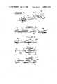
- FIG. 3is a schematic illustration, in perspective, depicting ion sputtering formation of micro orifices into a portion of the tubular assembly
- FIG. 4is a perspective view illustrating the alignment of the components of the tubular assembly, prior to assembly thereof;
- FIG. 5is a perspective view illustrating initial assembly of one component of the tubular assembly onto the other;
- FIG. 6is a perspective view showing an intermediate stage in the manufacture of the tubular assembly.
- FIG. 7is a perspective view depicting a completed tubular assembly according to this invention suitable for use as a ventricular catheter.
- a tubing assembly in accordance with this invention, generally designated as 21,is shown in FIG. 1 as a catheter component of an implantable cerebrospinal fluid pressure relief system, generally designated as 22.
- a system 22which maintains a desired predetermined intracranial pressure in a patient 23, also includes a pressure relief valve 24 and a drain catheter 25.
- the cerebrospinal fluid pressure relief system 22drains cerebrospinal fluid 26 from a ventricle 27 of the brain 28, the cerebrospinal fluid 14 passing through the pressure relief valve 24 and the drain catheter 25 for discharge into a selected location in the patient's body, such as an appropriate vein 29 to terminate within the right atrium of the heart 31 as illustrated.
- Other drainage locationssuch as the peritoneal cavity, can be selected instead.
- a typical pressure relief valve 24 in the pressure relief system 22includes means for adjusting the differential pressure threshold at which the valve 24 opens so that the hydrocephalus pressure relief system 22 can be adjusted to suit the specific requirements of an individual patient.
- Various pressure relief valve assembliesare known. Ones that are particularly suitable to this aspect of the invention are those that are commercially available from Cordis Corporation. In such valves, the dimensions thereof are selected so as to be compatible with subcutaneous implantation of the valve 24 over the cranium 32.
- FIG. 2Another suitable aspect of this invention is the inclusion of the tubing assembly 21 within an implantable pressure relief system such as that illustrated in FIG. 2, which is an intracranial pressure monitoring and cerebrospinal fluid drainage system.
- FIG. 2an implantable pressure relief system
- FIG. 2an intracranial pressure monitoring and cerebrospinal fluid drainage system.
- FIG. 2the ventricular catheter or tubing assembly 21 is inserted into a ventricle of the brain in a manner similar to that illustrated in FIG. 1.
- the catheter 21extends beyond the cranium 32 and the scalp of the patient.
- an introducer 33is provided for guiding the catheter 21 into the ventricle in accordance with generally known medical procedures.
- a tubing assembly, generally designated as 34,is included for joining the catheter 21 with a drip chamber 35 having fluid measurement graduations 36 for collection and measurement of cerebrospinal fluid that is drained from the ventricle. Intracranial pressure may be measured through a monitoring port 37.
- Drip chamber 35is part of a cerebrospinal fluid collection assembly 38 which may include a drainage bag 39.
- a monitoring assembly 41may also be included to permit monitoring of cerebrospinal fluid pressure by either a monometer 42 or through a pressure transducer port 43 for communication with any one of a variety of electronic pressure monitoring devices.
- a plurality of four-way valves 44, 45 and 46are preferably provided in the system of FIG. 2 in order to provide exceptional flexibility with regard to the various flow paths available within the system. Additional details of the pressure monitoring and fluid measuring and draining system illustrated in FIG. 2 are included in copending U.S. patent application Ser. No. 590,713, filed Mar. 16, 1984, the subject matter thereof being incorporated by reference hereinto.
- suchincludes a length of elastomeric tubing 51 and a length of tubing 52 that includes ion sputtered orifices 53.
- the ion sputtered length of tubingis of a length shorter than that of the elastomeric tubing 51.
- Preparation of the ion sputtered tubing 52is schematically illustrated in FIG. 3.
- An ion beam generator 54 of generally known constructionprovides an ion beam 55 from a source of gas such as argon or the like. Gas enters the ion beam generator 54 through a gas inlet 56, the ion beam generator 54 including an appropriate filament 57, anode 58, screen grid 59 and accelerator grid 61.
- Control of the ion beam 55is typically facilitated by a shield or mask 62.
- a length of tubing that is especially suitable for the formation of ion sputtered micro orifices thereinis positioned on the other side of the mask 62 in order to form the tubing 52 having the ion sputtered orifices 53.
- the tubing 52it is typically not possible to form the ion sputtered orifices 53 in elastomeric materials such as those out of which the remainder of the tubing assembly 21 is made, this being the elastomeric tubing 51.
- Fluoropolymersare particularly receptive to ion sputtering techniques, although they are much less desirable for use as ventricular catheters than are elastomeric materials such as silicone rubber products and the like.
- the ion sputtered tubing 52is of a relatively short length in order to minimize the surface area of the brain that is contacted by the ion sputtered non-elastomeric tubing 52, particularly during the implantation procedure.
- the ion sputtered non-elastomeric tubing 52is spaced from the leading end 63 of the tubing assembly 21.
- the leading end 63is made of a material that is elastomeric and exceptionally non-traumatic.
- the leading end 63is a continuous extension of the elastomeric tubing 51. The manufacture of the preferred tubing assembly 21 having these characteristics is illustrated in FIGS. 4 through 7.
- a length of elastomeric tubing 51is shown in an orientation for receiving the ion sputtered tubing 52 thereover.
- the preferred length of elastomeric tubing 51includes a proximal length 64 and a distal length 65 for inclusion as a part of the leading end 63.
- At least one radially directed opening 66is provided through the elastomeric tubing 51, thereby defining the proximal length 64 and the distal length 65 of the elastomeric tubing 51.
- Opening or openings 66are positioned for substantially underlying relationship with the ion sputtered orifices 53 of the tubing 52 when the tubing 52 is assembled over the elastomeric tubing 51 in order to provide a fluid passageway from the outside surface of the ion sputtered orifices 53, through the opening(s) 66 and through the proximal length 64 of tubing 51 for passage to the rest of the cerebrospinal fluid drainage system or the like. While it is important that the ion sputtered orifices 53 be of an extremely fine size, there is no such requirement for the opening(s) 66.
- FIG. 5illustrates an important aspect of this invention which insures the integrity of the assembly of the ion sputtered tubing 52 over the elastomeric tubing 51.
- a bead of medical adhesive 67is applied along both ends of the ion sputtered tubing 52.
- the bead of medical adhesive 67is applied around substantially the entire circumference of the ends of the ion sputtered tubing 52.
- Such beads of medical adhesive 67are preferably applied while the elastomeric tubing 51 is stretched as illustrated in FIG. 6 in order to facilitate passage of the beads 67 between the elastomeric tubing 51 and the ion sputtered tubing 52 in the vicinity of the ends of the ion sputtered tubing 52.
- the elastomeric tubing 51is relaxed as generally illustrated in FIG. 7, whereby the elastomeric tubing 51 is allowed to conform to its original dimensions, which assists in pulling the beads of medical adhesive 67 into the space between the elastomeric tubing 51 and the tubing 52, which space substantially closes between the orientation as illustrated in FIGS. 5 and 6 when the elastomeric tubing 51 was stretched and the closed orientation of FIG. 7.
- the distal length 65 of the elastomeric tubing 51is closed by affixing a plug 68 thereto, which may be an adhesive, a molded tip or the like.
- the internal diameter of the ion sputtered tubing 52is substantially the same as or slightly less than the outer diameter of the elastomeric tubing 51 in its unstretched or relaxed state in order to insure that the assembled tubing assembly 21 exhibits a frictional fit between the ion sputtered tubing 52 and the elastomeric tubing 51.
- a suitable medical adhesiveis one that readily bonds the components together at room temperature. Especially suitable medical adhesives include liquid silicone rubber or silicone elastomeric adhesives, or the like.
- suitable fluoropolymers for making sameinclude polytetrafluoroethylene resins including Teflon or other fluorine and/or chlorine containing fluoropolymers such as fluorinated ethylenepropylene.
- Materials of this typeare particularly susceptible to being ion sputtered in order to form micro orifices 53 therewithin. Sizing of the micro orifices is important in order to substantially prevent undesirable tissue ingrowth while the tubing assembly 21 is implanted in vivo for extended periods of time. It is important that the passageway into the tubing assembly 21 through the ion sputtered micro orifices 53 not be blocked by tissue ingrowth or by other blockages such as having protein and cell fragments enter the orifices 53.
- Such undesirable entry and ingrowth blockagescan be accomplished by providing the orifices 53 as ion sputtered micro orifices each of which has a size less than that of such growing tissue, protein, cell fragments or the like.
- the ion sputtered micro orifices 53will typically have a nominal diameter or a nominal opening width as small as on the order of about 5 microns up to a size at which ingrowth and blockage is substantially prevented in a patient, typically on the order of about 60 microns.
- a preferred size rangeis between about 10 and about 50 microns.
- holes made by more conventional procedures in elastomeric tubingsuch as silicone rubber have a size on the order of about 400 microns.
Landscapes
- Health & Medical Sciences (AREA)
- Heart & Thoracic Surgery (AREA)
- Biomedical Technology (AREA)
- Vascular Medicine (AREA)
- Engineering & Computer Science (AREA)
- Anesthesiology (AREA)
- Surgery (AREA)
- Hematology (AREA)
- Life Sciences & Earth Sciences (AREA)
- Animal Behavior & Ethology (AREA)
- General Health & Medical Sciences (AREA)
- Public Health (AREA)
- Veterinary Medicine (AREA)
- External Artificial Organs (AREA)
Abstract
Description
Claims (25)
Priority Applications (1)
| Application Number | Priority Date | Filing Date | Title |
|---|---|---|---|
| US06/614,633US4601724A (en) | 1984-05-29 | 1984-05-29 | Manufacture of tubing assembly for drainage catheter |
Applications Claiming Priority (1)
| Application Number | Priority Date | Filing Date | Title |
|---|---|---|---|
| US06/614,633US4601724A (en) | 1984-05-29 | 1984-05-29 | Manufacture of tubing assembly for drainage catheter |
Publications (1)
| Publication Number | Publication Date |
|---|---|
| US4601724Atrue US4601724A (en) | 1986-07-22 |
Family
ID=24462100
Family Applications (1)
| Application Number | Title | Priority Date | Filing Date |
|---|---|---|---|
| US06/614,633Expired - Fee RelatedUS4601724A (en) | 1984-05-29 | 1984-05-29 | Manufacture of tubing assembly for drainage catheter |
Country Status (1)
| Country | Link |
|---|---|
| US (1) | US4601724A (en) |
Cited By (31)
| Publication number | Priority date | Publication date | Assignee | Title |
|---|---|---|---|---|
| US4767418A (en)* | 1986-02-13 | 1988-08-30 | California Institute Of Technology | Luminal surface fabrication for cardiovascular prostheses |
| US4767400A (en)* | 1987-10-27 | 1988-08-30 | Cordis Corporation | Porous ventricular catheter |
| US4781704A (en)* | 1987-02-24 | 1988-11-01 | Entech, Inc. | Feeding tube assembly with collapsible outlet connector |
| US4861331A (en)* | 1988-03-24 | 1989-08-29 | Pudenz-Schulte Medical Research Corp. | Implantable shunt system and method of assembly |
| US4867740A (en)* | 1988-03-24 | 1989-09-19 | Pudenz-Schulte Medical Research Corp. | Multiple-membrane flow control valve and implantable shunt system |
| US4883453A (en)* | 1986-10-27 | 1989-11-28 | Ethicoh Inc. | Method of manufacturing synthetic vascular grafts |
| US5191898A (en)* | 1990-10-22 | 1993-03-09 | Millar Instruments, Inc. | Method and assembly for measuring intracranial fluid characateristics |
| US5385541A (en)* | 1992-04-24 | 1995-01-31 | Loma Linda University Medical Center | Cerebrospinal fluid shunt capable of minimal invasive revision |
| WO1996007448A1 (en)* | 1994-09-08 | 1996-03-14 | Saab Mark A | Variable stiffness balloon dilatation catheters |
| US5607463A (en)* | 1993-03-30 | 1997-03-04 | Medtronic, Inc. | Intravascular medical device |
| US5683357A (en)* | 1995-12-01 | 1997-11-04 | Magram; Gary | External cerebrospinal fluid drain apparatus |
| US5693011A (en)* | 1995-04-27 | 1997-12-02 | Surgical Dynamics, Inc. | Surgical suction cutting instrument |
| US6110155A (en)* | 1996-04-30 | 2000-08-29 | Medtronic, Inc. | Anti-inflammatory-agent-loaded catheter and method for preventing tissue fibrosis |
| US20030004495A1 (en)* | 1996-07-11 | 2003-01-02 | Eunoe, Inc. | Apparatus and methods for volumetric CSF removal |
| US20030032915A1 (en)* | 2001-08-09 | 2003-02-13 | Eunoe, Inc. | System and method for treating elevated intracranial pressure |
| US6575928B2 (en) | 1998-11-10 | 2003-06-10 | Eunoe, Inc. | Devices and methods for removing cerebrospinal fluids from a patient's CSF space |
| WO2004044655A1 (en)* | 2002-11-14 | 2004-05-27 | Q-Chip Limited | Method for the bulk machining of fluoropolymer substrates |
| US20040236309A1 (en)* | 2003-05-19 | 2004-11-25 | Benson Yang | Mesh ventricular catheter with antithrombogenic coating |
| US20040260249A1 (en)* | 2003-06-23 | 2004-12-23 | Codman & Shurtleff, Inc. | Catheter with block-overriding system |
| US6875192B1 (en) | 1998-11-10 | 2005-04-05 | Eunoe, Inc. | Devices and methods for removing cerebrospinal fluids from a patient's CSF space |
| US20050113802A1 (en)* | 2001-03-01 | 2005-05-26 | Watson David A. | Process for creating an ingrowth preventing indwelling catheter assembly |
| US20050228360A1 (en)* | 2004-04-08 | 2005-10-13 | Scimed Life Systems, Inc. | Medical devices including aerated adhesive bonds and methods of forming the same |
| US20080272171A1 (en)* | 2007-05-01 | 2008-11-06 | Tyco Healthcare Group Lp | Anvil position detector for a surgical stapler |
| US20110166495A1 (en)* | 2008-07-02 | 2011-07-07 | Christoph Miethke | Cerebrospinal fluid drainage |
| US20120302938A1 (en)* | 2010-03-19 | 2012-11-29 | University Of Washington | Drainage systems for excess body fluids and associated methods |
| US20150005800A1 (en)* | 2012-01-27 | 2015-01-01 | Siad Healthcare S.P.A. | Implantable device for the treatment of hydrocephalus syndrome and the corresponding method |
| CN106267523A (en)* | 2016-07-25 | 2017-01-04 | 成都嘉宝祥生物科技有限公司 | A kind of cranium brain drainage tube secured adjusted method |
| US10166375B2 (en) | 2010-03-19 | 2019-01-01 | University Of Washington | Body fluid drainage system |
| US10183143B2 (en) | 2013-03-15 | 2019-01-22 | Bitol Designs, Llc | Occlusion resistant catheter and method of use |
| US10413710B2 (en) | 2014-01-16 | 2019-09-17 | University Of Washington | Pressure reference assemblies for body fluid drainage systems and associated methods |
| WO2023034604A1 (en)* | 2021-09-03 | 2023-03-09 | Freeflow Medical Devices Llc | Hydrocephalus shunt |
Citations (10)
| Publication number | Priority date | Publication date | Assignee | Title |
|---|---|---|---|---|
| US3373735A (en)* | 1965-10-21 | 1968-03-19 | John P. Gallagher | Medical-surgical tube |
| US3421510A (en)* | 1966-01-10 | 1969-01-14 | Edward L Kettenbach | Drain having shielded suction tube |
| US3426759A (en)* | 1966-04-04 | 1969-02-11 | Davol Inc | Abdominal suction drainage tube |
| US3435827A (en)* | 1966-05-09 | 1969-04-01 | Rendall Co The | Drainage device with shielded drainage orifice |
| US3669116A (en)* | 1970-07-06 | 1972-06-13 | Heyer Schulte Corp | Drainage catheter with anticlogging means |
| US3690323A (en)* | 1970-12-01 | 1972-09-12 | Us Army | Device for draining ventricular fluid in cases of hydrocephalus |
| US4375816A (en)* | 1979-10-17 | 1983-03-08 | Michele Labianca | Catheters for shunting systems for the treatment of hydrocephalus |
| US4377169A (en)* | 1981-06-10 | 1983-03-22 | Banks Bruce A | Ion beam sputter-etched ventricular catheter for hydrocephalus shunt |
| US4391276A (en)* | 1980-12-16 | 1983-07-05 | Harrison Lazarus | Peritoneal catheter |
| US4398910A (en)* | 1981-02-26 | 1983-08-16 | Blake L W | Wound drain catheter |
- 1984
- 1984-05-29USUS06/614,633patent/US4601724A/ennot_activeExpired - Fee Related
Patent Citations (10)
| Publication number | Priority date | Publication date | Assignee | Title |
|---|---|---|---|---|
| US3373735A (en)* | 1965-10-21 | 1968-03-19 | John P. Gallagher | Medical-surgical tube |
| US3421510A (en)* | 1966-01-10 | 1969-01-14 | Edward L Kettenbach | Drain having shielded suction tube |
| US3426759A (en)* | 1966-04-04 | 1969-02-11 | Davol Inc | Abdominal suction drainage tube |
| US3435827A (en)* | 1966-05-09 | 1969-04-01 | Rendall Co The | Drainage device with shielded drainage orifice |
| US3669116A (en)* | 1970-07-06 | 1972-06-13 | Heyer Schulte Corp | Drainage catheter with anticlogging means |
| US3690323A (en)* | 1970-12-01 | 1972-09-12 | Us Army | Device for draining ventricular fluid in cases of hydrocephalus |
| US4375816A (en)* | 1979-10-17 | 1983-03-08 | Michele Labianca | Catheters for shunting systems for the treatment of hydrocephalus |
| US4391276A (en)* | 1980-12-16 | 1983-07-05 | Harrison Lazarus | Peritoneal catheter |
| US4398910A (en)* | 1981-02-26 | 1983-08-16 | Blake L W | Wound drain catheter |
| US4377169A (en)* | 1981-06-10 | 1983-03-22 | Banks Bruce A | Ion beam sputter-etched ventricular catheter for hydrocephalus shunt |
Non-Patent Citations (2)
| Title |
|---|
| C. E. Garner et al., article, "Directed Ion Beam Sputter Etching of Polytetrafluoroethylene (Teflon) Using an Argon Ion Source", 1982, pp. 351-362. |
| C. E. Garner et al., article, Directed Ion Beam Sputter Etching of Polytetrafluoroethylene (Teflon) Using an Argon Ion Source , 1982, pp. 351 362.* |
Cited By (46)
| Publication number | Priority date | Publication date | Assignee | Title |
|---|---|---|---|---|
| US4767418A (en)* | 1986-02-13 | 1988-08-30 | California Institute Of Technology | Luminal surface fabrication for cardiovascular prostheses |
| US4883453A (en)* | 1986-10-27 | 1989-11-28 | Ethicoh Inc. | Method of manufacturing synthetic vascular grafts |
| US4781704A (en)* | 1987-02-24 | 1988-11-01 | Entech, Inc. | Feeding tube assembly with collapsible outlet connector |
| US4767400A (en)* | 1987-10-27 | 1988-08-30 | Cordis Corporation | Porous ventricular catheter |
| US4861331A (en)* | 1988-03-24 | 1989-08-29 | Pudenz-Schulte Medical Research Corp. | Implantable shunt system and method of assembly |
| US4867740A (en)* | 1988-03-24 | 1989-09-19 | Pudenz-Schulte Medical Research Corp. | Multiple-membrane flow control valve and implantable shunt system |
| US5191898A (en)* | 1990-10-22 | 1993-03-09 | Millar Instruments, Inc. | Method and assembly for measuring intracranial fluid characateristics |
| US5385541A (en)* | 1992-04-24 | 1995-01-31 | Loma Linda University Medical Center | Cerebrospinal fluid shunt capable of minimal invasive revision |
| US5607463A (en)* | 1993-03-30 | 1997-03-04 | Medtronic, Inc. | Intravascular medical device |
| WO1996007448A1 (en)* | 1994-09-08 | 1996-03-14 | Saab Mark A | Variable stiffness balloon dilatation catheters |
| US5499973A (en)* | 1994-09-08 | 1996-03-19 | Saab; Mark A. | Variable stiffness balloon dilatation catheters |
| US5693011A (en)* | 1995-04-27 | 1997-12-02 | Surgical Dynamics, Inc. | Surgical suction cutting instrument |
| US5683357A (en)* | 1995-12-01 | 1997-11-04 | Magram; Gary | External cerebrospinal fluid drain apparatus |
| US6110155A (en)* | 1996-04-30 | 2000-08-29 | Medtronic, Inc. | Anti-inflammatory-agent-loaded catheter and method for preventing tissue fibrosis |
| US20030004495A1 (en)* | 1996-07-11 | 2003-01-02 | Eunoe, Inc. | Apparatus and methods for volumetric CSF removal |
| US6575928B2 (en) | 1998-11-10 | 2003-06-10 | Eunoe, Inc. | Devices and methods for removing cerebrospinal fluids from a patient's CSF space |
| US6875192B1 (en) | 1998-11-10 | 2005-04-05 | Eunoe, Inc. | Devices and methods for removing cerebrospinal fluids from a patient's CSF space |
| US8376980B2 (en)* | 2001-03-01 | 2013-02-19 | David A. Watson | Ingrowth preventing indwelling catheter assembly |
| US20100179471A1 (en)* | 2001-03-01 | 2010-07-15 | Watson David A | Ingrowth preventing indwelling catheter assembly |
| US20050113802A1 (en)* | 2001-03-01 | 2005-05-26 | Watson David A. | Process for creating an ingrowth preventing indwelling catheter assembly |
| US7763142B2 (en) | 2001-03-01 | 2010-07-27 | Watson David A | Process for creating an ingrowth preventing indwelling catheter assembly |
| US20100282394A1 (en)* | 2001-03-01 | 2010-11-11 | Watson David A | Process for creating an ingrowth preventing indwelling catheter assembly |
| US20030032915A1 (en)* | 2001-08-09 | 2003-02-13 | Eunoe, Inc. | System and method for treating elevated intracranial pressure |
| US7025739B2 (en) | 2001-08-09 | 2006-04-11 | Integra Lifesciences Corporation | System and method for treating elevated intracranial pressure |
| WO2004044655A1 (en)* | 2002-11-14 | 2004-05-27 | Q-Chip Limited | Method for the bulk machining of fluoropolymer substrates |
| US20040236309A1 (en)* | 2003-05-19 | 2004-11-25 | Benson Yang | Mesh ventricular catheter with antithrombogenic coating |
| US7226441B2 (en)* | 2003-06-23 | 2007-06-05 | Codman & Shurtleff, Inc. | Catheter with block-overriding system |
| US20040260249A1 (en)* | 2003-06-23 | 2004-12-23 | Codman & Shurtleff, Inc. | Catheter with block-overriding system |
| US20050228360A1 (en)* | 2004-04-08 | 2005-10-13 | Scimed Life Systems, Inc. | Medical devices including aerated adhesive bonds and methods of forming the same |
| US7674251B2 (en) | 2004-04-08 | 2010-03-09 | Boston Scientific Scimed, Inc. | Medical devices including aerated adhesive bonds and methods of forming the same |
| US8043278B2 (en) | 2004-04-08 | 2011-10-25 | Boston Scientific Scimed, Inc. | Medical devices including aerated adhesive bonds and methods of forming the same |
| US20100236710A1 (en)* | 2004-04-08 | 2010-09-23 | Boston Scientific Scimed, Inc. | Medical Devices Including Aerated Adhesive Bonds and Methods of Forming the Same |
| US8028882B2 (en) | 2007-05-01 | 2011-10-04 | Tyco Healthcare Group | Anvil position detector for a surgical stapler |
| US20080272171A1 (en)* | 2007-05-01 | 2008-11-06 | Tyco Healthcare Group Lp | Anvil position detector for a surgical stapler |
| US9295821B2 (en) | 2008-07-02 | 2016-03-29 | Christoph Miethke | Cerebrospinal fluid drainage |
| US20110166495A1 (en)* | 2008-07-02 | 2011-07-07 | Christoph Miethke | Cerebrospinal fluid drainage |
| US10166375B2 (en) | 2010-03-19 | 2019-01-01 | University Of Washington | Body fluid drainage system |
| US20180028794A1 (en)* | 2010-03-19 | 2018-02-01 | University Of Washington | Drainage systems for excess body fluids and associated methods |
| US20120302938A1 (en)* | 2010-03-19 | 2012-11-29 | University Of Washington | Drainage systems for excess body fluids and associated methods |
| US11247030B2 (en) | 2010-03-19 | 2022-02-15 | University Of Washington | Body fluid drainage system |
| US9168363B2 (en)* | 2012-01-27 | 2015-10-27 | Siad Healthcare S.P.A. | Implantable device for the treatment of hydrocephalus syndrome and the corresponding method |
| US20150005800A1 (en)* | 2012-01-27 | 2015-01-01 | Siad Healthcare S.P.A. | Implantable device for the treatment of hydrocephalus syndrome and the corresponding method |
| US10183143B2 (en) | 2013-03-15 | 2019-01-22 | Bitol Designs, Llc | Occlusion resistant catheter and method of use |
| US10413710B2 (en) | 2014-01-16 | 2019-09-17 | University Of Washington | Pressure reference assemblies for body fluid drainage systems and associated methods |
| CN106267523A (en)* | 2016-07-25 | 2017-01-04 | 成都嘉宝祥生物科技有限公司 | A kind of cranium brain drainage tube secured adjusted method |
| WO2023034604A1 (en)* | 2021-09-03 | 2023-03-09 | Freeflow Medical Devices Llc | Hydrocephalus shunt |
Similar Documents
| Publication | Publication Date | Title |
|---|---|---|
| US4601724A (en) | Manufacture of tubing assembly for drainage catheter | |
| EP0066685B1 (en) | Ion beam sputter-etched ventricular catheter for hydrocephalus shunt | |
| US4790810A (en) | Ureteral connector stent | |
| US4973319A (en) | Slit valve medical catheter | |
| EP0125844B1 (en) | Valved two-way catheter | |
| US4382445A (en) | Physiological fluid shunt system and improvements therefor | |
| US8376980B2 (en) | Ingrowth preventing indwelling catheter assembly | |
| US5360397A (en) | Hemodiaylsis catheter and catheter assembly | |
| US5833664A (en) | Noded cuffs for transcutaneous or intrabody prosthetic devices | |
| US5662600A (en) | Burr-hole flow control device | |
| EP0370720B1 (en) | Improved hemostasis valve | |
| US4701166A (en) | Valved two-way catheter | |
| US4578057A (en) | Ventricular right angle connector and system | |
| US5207649A (en) | Introducer sheath having a hemostatic closure | |
| US4671796A (en) | Valved two-way catheter | |
| US3654932A (en) | Surgical drain for shunting fluid | |
| US8092432B2 (en) | Outdwelling slit valves and assemblies for medical liquid flow through a cannula and related methods | |
| JP5059028B2 (en) | Implantable microsystem for the treatment of hydrocephalus | |
| US4624657A (en) | Medical devices having inflatable portions | |
| SE462416B (en) | SKIN OR MUSHROOMS | |
| GB2079609A (en) | Surgical drain | |
| WO1993002734A1 (en) | Hemostasis valve | |
| JPH1080491A (en) | Arterial catheter having improved flow characteristic and catheter/needle assembly and its use method | |
| US5098411A (en) | Closed end hollow stylet assembly | |
| US3452757A (en) | Two-way flushing device for treatment of hydrocephalus |
Legal Events
| Date | Code | Title | Description |
|---|---|---|---|
| AS | Assignment | Owner name:CORDIS CORPORATION, MIAMI, FLA., A FLA CORP. Free format text:ASSIGNMENT OF ASSIGNORS INTEREST.;ASSIGNORS:HOOVEN, MICHAEL D.;TREMULIS, WILLIAM S.;REEL/FRAME:004278/0628 Effective date:19840509 | |
| CC | Certificate of correction | ||
| FPAY | Fee payment | Year of fee payment:4 | |
| FEPP | Fee payment procedure | Free format text:PAYOR NUMBER ASSIGNED (ORIGINAL EVENT CODE: ASPN); ENTITY STATUS OF PATENT OWNER: LARGE ENTITY | |
| FPAY | Fee payment | Year of fee payment:8 | |
| AS | Assignment | Owner name:ELEKTA AB, SWEDEN Free format text:ASSIGNMENT OF ASSIGNORS INTEREST;ASSIGNOR:CORDIS CORPORATION;REEL/FRAME:008478/0819 Effective date:19970411 | |
| REMI | Maintenance fee reminder mailed | ||
| LAPS | Lapse for failure to pay maintenance fees | ||
| AS | Assignment | Owner name:J.H. WHITNEY & CO., CONNECTICUT Free format text:SECURITY INTEREST;ASSIGNORS:NITINOL MEDICAL TECHNOLOGIES, INC.;NMT NEUROSCIENCES (IP) INC.;NMT NEUROSCIENCES (INTERNATIONAL) INC.;AND OTHERS;REEL/FRAME:009375/0116 Effective date:19980708 Owner name:NMT NEUROSCIENCES (IP), INC., A DELAWARE CORPORATI Free format text:ASSIGNMENT OF ASSIGNORS INTEREST;ASSIGNOR:ELEKTA AB (PUBL) A SWEDISH CORPORATION;REEL/FRAME:009375/0712 Effective date:19980708 | |
| FP | Lapsed due to failure to pay maintenance fee | Effective date:19980722 | |
| AS | Assignment | Owner name:NMT MEDICAL, INC., MASSACHUSETTS Free format text:CHANGE OF NAME;ASSIGNOR:NMT NEUROSCIENCES (IP), INC. (A DELAWARE CORPORATION);REEL/FRAME:010206/0089 Effective date:19990603 | |
| AS | Assignment | Owner name:BROWN BROTHERS HARRIMAN & CO., MASSACHUSETTS Free format text:COLLATERAL ASSIGNMENT;ASSIGNOR:NMT MEDICAL, INC. F/K/A NITINOL MEDICAL TECHNOLOGIES, INC.;REEL/FRAME:010247/0919 Effective date:19990913 | |
| AS | Assignment | Owner name:NMT NEUROSCIENCES (INTERNATIONAL), INC., MASSACHUS Free format text:SECURITY INTEREST TERMINATION;ASSIGNOR:J.H. WHITNEY & CO.;REEL/FRAME:010668/0425 Effective date:19991020 Owner name:NMT INVESTMENTS CORP., MASSACHUSETTS Free format text:SECURITY INTEREST TERMINATION;ASSIGNOR:J.H. WHITNEY & CO.;REEL/FRAME:010668/0425 Effective date:19991020 Owner name:NMT NEUROSCIENCES (U.S.), INC., MASSACHUSETTS Free format text:SECURITY INTEREST TERMINATION;ASSIGNOR:J.H. WHITNEY & CO.;REEL/FRAME:010668/0425 Effective date:19991020 Owner name:NMT NEUROSCIENCES (IP), INC., MASSACHUSETTS Free format text:SECURITY INTEREST TERMINATION;ASSIGNOR:J.H. WHITNEY & CO.;REEL/FRAME:010668/0425 Effective date:19991020 Owner name:NMT HEART, INC., MASSACHUSETTS Free format text:SECURITY INTEREST TERMINATION;ASSIGNOR:J.H. WHITNEY & CO.;REEL/FRAME:010668/0425 Effective date:19991020 Owner name:NMT MEDICAL, INC. (F/K/A NITINOL MEDICAL TECHNOLOG Free format text:SECURITY INTEREST TERMINATION;ASSIGNOR:J.H. WHITNEY & CO.;REEL/FRAME:010668/0425 Effective date:19991020 Owner name:NMT NEUROSCIENCES INNOVASIVE SYSTEMS, INC. (F/K/A Free format text:SECURITY INTEREST TERMINATION;ASSIGNOR:J.H. WHITNEY & CO.;REEL/FRAME:010668/0425 Effective date:19991020 | |
| AS | Assignment | Owner name:BROWN BROTHERS HARRIMAN & CO., MASSACHUSETTS Free format text:SECURITY INTEREST TERMINATION RECORDED AT REEL 10247 FRAME 0919;ASSIGNOR:NMT MEDICAL, INC.;REEL/FRAME:011675/0812 Effective date:20010404 | |
| STCH | Information on status: patent discontinuation | Free format text:PATENT EXPIRED DUE TO NONPAYMENT OF MAINTENANCE FEES UNDER 37 CFR 1.362 |