US4601491A - Pipe connector - Google Patents
Pipe connectorDownload PDFInfo
- Publication number
- US4601491A US4601491AUS06/543,590US54359083AUS4601491AUS 4601491 AUS4601491 AUS 4601491AUS 54359083 AUS54359083 AUS 54359083AUS 4601491 AUS4601491 AUS 4601491A
- Authority
- US
- United States
- Prior art keywords
- pin
- box
- connector
- crest
- crests
- Prior art date
- Legal status (The legal status is an assumption and is not a legal conclusion. Google has not performed a legal analysis and makes no representation as to the accuracy of the status listed.)
- Expired - Lifetime
Links
- 239000000463materialSubstances0.000claimsdescription10
- 230000004323axial lengthEffects0.000claimsdescription6
- 230000013011matingEffects0.000claimsdescription5
- 239000012530fluidSubstances0.000claimsdescription3
- 238000005452bendingMethods0.000abstractdescription7
- 230000036316preloadEffects0.000description6
- 238000005259measurementMethods0.000description4
- 239000004020conductorSubstances0.000description2
- 238000002347injectionMethods0.000description2
- 239000007924injectionSubstances0.000description2
- 238000009434installationMethods0.000description2
- 238000007789sealingMethods0.000description2
- 238000003466weldingMethods0.000description2
- 241000282472Canis lupus familiarisSpecies0.000description1
- 229910000831SteelInorganic materials0.000description1
- 230000008602contractionEffects0.000description1
- 230000007423decreaseEffects0.000description1
- 230000001627detrimental effectEffects0.000description1
- 238000010586diagramMethods0.000description1
- 238000005553drillingMethods0.000description1
- 230000009977dual effectEffects0.000description1
- 230000000694effectsEffects0.000description1
- 238000005461lubricationMethods0.000description1
- 238000004519manufacturing processMethods0.000description1
- 238000000034methodMethods0.000description1
- 230000002028prematureEffects0.000description1
- 230000000284resting effectEffects0.000description1
- 230000000717retained effectEffects0.000description1
- 239000010959steelSubstances0.000description1
Images


Classifications
- F—MECHANICAL ENGINEERING; LIGHTING; HEATING; WEAPONS; BLASTING
- F16—ENGINEERING ELEMENTS AND UNITS; GENERAL MEASURES FOR PRODUCING AND MAINTAINING EFFECTIVE FUNCTIONING OF MACHINES OR INSTALLATIONS; THERMAL INSULATION IN GENERAL
- F16L—PIPES; JOINTS OR FITTINGS FOR PIPES; SUPPORTS FOR PIPES, CABLES OR PROTECTIVE TUBING; MEANS FOR THERMAL INSULATION IN GENERAL
- F16L15/00—Screw-threaded joints; Forms of screw-threads for such joints
- F16L15/001—Screw-threaded joints; Forms of screw-threads for such joints with conical threads
- F16L15/003—Screw-threaded joints; Forms of screw-threads for such joints with conical threads with sealing rings
- E—FIXED CONSTRUCTIONS
- E21—EARTH OR ROCK DRILLING; MINING
- E21B—EARTH OR ROCK DRILLING; OBTAINING OIL, GAS, WATER, SOLUBLE OR MELTABLE MATERIALS OR A SLURRY OF MINERALS FROM WELLS
- E21B17/00—Drilling rods or pipes; Flexible drill strings; Kellies; Drill collars; Sucker rods; Cables; Casings; Tubings
- E21B17/006—Accessories for drilling pipes, e.g. cleaners
- E—FIXED CONSTRUCTIONS
- E21—EARTH OR ROCK DRILLING; MINING
- E21B—EARTH OR ROCK DRILLING; OBTAINING OIL, GAS, WATER, SOLUBLE OR MELTABLE MATERIALS OR A SLURRY OF MINERALS FROM WELLS
- E21B17/00—Drilling rods or pipes; Flexible drill strings; Kellies; Drill collars; Sucker rods; Cables; Casings; Tubings
- E21B17/02—Couplings; joints
- E21B17/04—Couplings; joints between rod or the like and bit or between rod and rod or the like
- E21B17/042—Threaded
- E21B17/043—Threaded with locking means
- F—MECHANICAL ENGINEERING; LIGHTING; HEATING; WEAPONS; BLASTING
- F16—ENGINEERING ELEMENTS AND UNITS; GENERAL MEASURES FOR PRODUCING AND MAINTAINING EFFECTIVE FUNCTIONING OF MACHINES OR INSTALLATIONS; THERMAL INSULATION IN GENERAL
- F16L—PIPES; JOINTS OR FITTINGS FOR PIPES; SUPPORTS FOR PIPES, CABLES OR PROTECTIVE TUBING; MEANS FOR THERMAL INSULATION IN GENERAL
- F16L37/00—Couplings of the quick-acting type
- F16L37/62—Couplings of the quick-acting type pneumatically or hydraulically actuated
- G—PHYSICS
- G01—MEASURING; TESTING
- G01B—MEASURING LENGTH, THICKNESS OR SIMILAR LINEAR DIMENSIONS; MEASURING ANGLES; MEASURING AREAS; MEASURING IRREGULARITIES OF SURFACES OR CONTOURS
- G01B3/00—Measuring instruments characterised by the use of mechanical techniques
- G01B3/46—Plug gauges for internal dimensions with engaging surfaces which are at a fixed distance, although they may be preadjustable
- Y—GENERAL TAGGING OF NEW TECHNOLOGICAL DEVELOPMENTS; GENERAL TAGGING OF CROSS-SECTIONAL TECHNOLOGIES SPANNING OVER SEVERAL SECTIONS OF THE IPC; TECHNICAL SUBJECTS COVERED BY FORMER USPC CROSS-REFERENCE ART COLLECTIONS [XRACs] AND DIGESTS
- Y10—TECHNICAL SUBJECTS COVERED BY FORMER USPC
- Y10S—TECHNICAL SUBJECTS COVERED BY FORMER USPC CROSS-REFERENCE ART COLLECTIONS [XRACs] AND DIGESTS
- Y10S285/00—Pipe joints or couplings
- Y10S285/921—Snap-fit
Definitions
- the inventionrelates to pipe connectors, and in particular, to releasable connectors for which rotation during assembly is difficult, such as piles, risers and conductors used for offshore oil production.
- Risers and conductorsusually in the 20 inch to 30 inch diameter range, and in joints about 50 feet long are sometimes pile driven. They must reliably support tension placed on them when tensioning or running the string during drilling and producing operations. They must also tolerate high bending forces caused, for instance, by ocean currents.
- a releasable pipe connectorwhich is circumferentially oriented and axially snapped together.
- the connectormay be rotated for disassembly and may be easily manufactured.
- the connectorcomprises a cylindrical pin and box each having frustoconical surfaces which are telescopically engageable.
- Helical thread forms on each of the pin and boxhave crests of discreet axial length, rounded roots, and an abutting flank facing away from the open end.
- the pin and boxeach have a secondary radially extending surface facing toward the open end. In a preferred embodiment this is the shoulder of one member, and an abutting surface on the other.
- the lengths of crestsare related to the overlap and the frustoconical taper, so that when stabbing occurs in the properly aligned position, initial contact is made between the crests.
- the boxexpands and the pin compresses while the crests ride over one another, snapping into place beyond the crest contact point.
- a double start thread formis arranged so that the crest surfaces between the two starts are of different axial lengths, thereby providing the ability to slide on the crest surfaces over both threads while engaging only in one.
- a preferred means for aligning a connectorinvolves a slot in the box member with an alignment key secured to the pin member. This is arranged to permit relative axial motion but to prevent rotation. The key may be removed to permit disassembly of the joint.
- each thread formmay also include a centralizing surface in each thread form. This is located between crests and intermediate the radial dimension of the crest surface and the root. These surfaces are in contact after the joint has been snapped together and are preferably in force fit contact.
- the connectormay be easily manufactured since helical threads are easy to machine with precision. With proper alignment, the crest surfaces first make contact, with the box expanding and the pin contracting, as the members are forced together.
- the connectormay be designed to operate below the elastic limit of the materials, or it may be designed to operate beyond the elastic limit where a more consistent reliable tooth engagement is achieved, at the expense of higher stabbing forces.
- a slight angleis included between the thread flank and the other abutting surface so that the radial movement of the connectors toward their original size operates against the flank to axially preload the connector.
- the centralizing surfaceis provided to avoid the possibility that the teeth on one side overengage when bending is applied to the connector. Overengagement on one side tends to result in insufficient engagement on the opposite side and possible zippering action or inadvertent release of the connector.
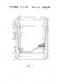
- FIG. 1is a general arrangement of the connector showing the pin and box and the frustoconical surface
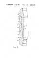
- FIG. 2is a sectional elevation of one thread form, while FIGS. 2a, 2b, 2c and 2d are details of the interengaging helical thread form during engagement and at the engaged position;
- FIG. 3is a stress/strain diagram which illustrates the elastic strain range
- FIGS. 4a & 4billustrate measurements to be made for providing proper alignment of the pin and box
- FIGS. 5a, 5b and 5cillustrate the gauge which may be employed for this purpose
- FIGS. 6 & 6aillustrate an alignment key
- FIG. 7illustrates a thread form where the taper of the crests are steeper than that of the frustoconical surface
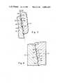
- FIG. 8illustrates a thread form having a centralizing surface
- FIG. 9is a detail of the thread form of FIG. 8.
- the cylindrical pin 10has a first end 12 securable by welding to a pipe (not shown), and an open end 14.
- a loading shoulder 16is provided to engage the pin for axially clamping.
- the pinincludes a frustoconical outer surface 18 with a stress relief groove 20 located at one end.
- the pinalso includes shoulder 24 in the form of radially extending surface facing toward the open end 14.
- a cylindrical box 30has a first end 32 securable to a pipe (not shown), and a second open end 34.
- the boxalso includes a loading shoulder 36 for axially clamping the box, and a frustoconical inner surface 38. It includes a stress relief groove 42 and a seal ring groove 44. An "O" ring seal 45 is located in this groove.
- the boxalso has an end surface 46 in the form of a radially extending surface facing the open end 34. Clamps (not shown) are used to supply the required axial stabbing force, and then removed.
- FIG. 2the helical thread form is shown in detail.
- the threadis shown in its engaged position in FIGS. 2 and 2d.
- Pin 10has multiple start threads which in this case are 180 degrees apart.
- a first thread with a narrow groove 50 and a second with a wide groove 52result in alternate crest surfaces 54 and 56, having different axial extents, crest 54 being wide, and crest 56 being narrow.
- the box 30has a dual start thread form 57 with narrow groove 58 and wide groove 60 producing a wide crest 62 and a narrow crest 63.
- Pin thread form 49includes flanks 64 facing away from the open end of the pin.
- edges 66 of the flank and the crestshould be as sharp as possible since rounding these edges decreases the amount of load bearing surface of flank 64.
- the grooves 50 and 52are rounded at the root as shown at 68 to enhance the fatigue life of the connector by reducing stress concentrations at small root radii.
- the box 30has flanks 70 facing away from the open end of the box.
- the roots or grooves 60 and 58also are rounded 72.
- the box 30may also include a threaded opening 73 with plug 74. This permits injection of a fluid under pressure injection for the purpose of reducing the torque required to break the connector loose.
- overlapis used to describe the dimensional difference between corresponding radii of crests such as 56 and 63 with the pin and box in the "as fabricated" condition. This is prior to assembly with both components in the unstressed condition. After assembly, the corresponding distance 76 is the tooth engagement, representing the distance of engagement of flanks 64 and 70. This tooth engagement will be less than the overlap when shrink fit is obtained, with strain locked in the pin and box.
- the term residual overlapis used to describe the dimensional difference between corresponding radii of crests such as 56 and 63 if the components were allowed to go to the unstressed condition after assembly. If the elastic limit were not exceeded during installation then the overlap and residual overlap would be identical. If, however, the elastic limit is exceeded, then the residual overlap would be less than the initial overlap.
- the angle of the flanks 64 and 70 with respect to shoulder 24 and to box end 45are each 12° and preferably within the range of 0° to 20°. As the pin and box attempt to restore themselves to the unstressed condition the abutting flanks 64 and 70 cooperate along with complimentary pin and box surfaces 24 and 45 to provide an axial load on the pin and box, compressing the box end against pin shoulder 24. For pile driving, it is important that the connector be snug and for bending some preload is to be preferred. Accomplishment of preload is a function of the difference between the tooth engagement and residual overlap, this representing the residual strain and concomitant stress existing in the box and pin. The amount of the preload is a function of the included angle.
- FIG. 2aillustrates the position of the pin 10 and box 30 during the stabbing operation as initial contact is made.
- the axial distance which the pin must travel into the box after contact and before shoulderingis referred to as the standoff. It is determined by the amount of overlap and the taper angle. In order to avoid the possibility of a crest engaging a groove before shouldering occurs, the lead of the thread must be greater than the standoff.
- the crest widthis then selected so that when stabbing occurs initial contact is made as illustrated between wide crest 54 and the narrow crest 63.
- FIG. 3illustrates a typical stress/strain curve for steel.
- the materialWhen operating along the stress/strain curve 80 below the elastic limit 82 the material will return when unstressed to its original condition 84.
- the difference in strain between points 82 and 84may be considered the elastic strain range as indicated by 86.
- the materialwill not return to its original condition, but will return to point 90 with a permanent residual strain in the material.
- the materialnow acts elastically throughout elastic strain range 92, representing the difference between points 88 and 90.
- the connector in its maximum strain conditionillustrated in FIG. 2c
- the residual overlapwill be the same as the original overlap. Tooth engagement will approach this overlap as a maximum, when the residual radial strain on the pin and box reach zero. If the elastic limit is not reached, then the tooth engagement is reduced. If on the other hand, the maximum strain exceeds the elastic limit such as to point 88, then the full elastic range 92 will be available for contracting the connector box and expanding the pin.
- the effect of dimensional tolerances on preload and tooth engagementmay be minimized by designing the connector so that the elastic limit is exceeded even when the overlap is at the minimum value permitted by dimensional tolerances. Accordingly, one may design the connector to operate in this condition exceeding the elastic limit.
- the thread formsare helical there is only one circumferential relationship where the above described characteristics will be obtained. It accordingly is required to locate the proper circumferential alignment for aligning the connectors.
- the means for alignmentmay be as simple as marking on the outside of the pin and box, or may be the alignment key illustrated in FIG. 6.
- a selected dimension 96is to be used for both the pin 10 and the box 30. The location around the circumference is determined where this dimension is a preselected value 96 on pin between shoulder 24 and measuring point 98. This measuring point is selected on the flank 64 facing away from the open end of the pin. The inward dimension 100 from the surface of crest 54 is selected as one-half of the desired tooth engagement. With this point located, a similar point is located on box 30 with the dimension being established between the pin end 45 and the corresponding engaging flank 64. The pin and box components are then either marked or machined in accordance with the measurements so that the located points are circumferentially aligned when the connector is to be stabbed together.
- FIGS. 5a, 5b and 5cA typical gauge for this purpose is illustrated in FIGS. 5a, 5b and 5c.
- Gauge set 101consists of a box gauge 102 and a pin gauge 103 which are constructed from 1/8 inch thick tooling plate.
- the box and pin gaugeshave tapered mating surfaces 104 and 105 respectively, the taper matching the frustoconical taper 18, 38 of the connector. Tooth 106 on the box gauge and tooth 107 on the pin gauge are engageable at the predetermined distance 96 from shoulder surface 108 and face surface 109 of the gauges.
- FIGS. 5b and 5cThe use of the gauges is shown in FIGS. 5b and 5c.
- the shoulder 108 of the gauge 102is held against the box face 45 with the mating surface 104 against the surface of crests 62 and 63. Holding the gauge parallel to the box axis it is moved circumferentially until flank 110 of tooth 106 contacts flank 70 of the box. The gauge location is then marked on the outside of the box.
- the face 109 of gauge 103is held against the pin shoulder 24 with the mating surface 105 against the surface of crests 54 and 56. It is moved circumferentially until flank 111 of tooth 107 contacts flank 64 of the pin. This location is marked on the pin.
- Calibration of the gaugesmay be checked by resting the gauges together as shown in FIG. 5a. They are correct if the gap 112 between mating surfaces 104 and 105 is equal to the desired engagement 76. This is the distance which the crest surfaces extend beyond each other when the predetermined distance 96 is held. It does not really matter what dimension 96 is, so long as it is the same for both gauges.
- FIG. 6A preferred alignment means is shown in FIG. 6 with detail of the alignment key being shown in FIG. 6a.
- a slot 120is machined in the box and an alignment key 122 is fastened to the pin with screws 124. This not only permits alignment of the pin and box for stabbing, but also operates as a guide to maintain this alignment during the clamping operation.
- the alignment key 122also serves as an anti-rotation device to preclude any possibility of the connector rotating loose during operation. At the time it is desired to disassemble this joint, the alignment key is removed and the joint may be unscrewed.
- the maximum tooth engagementis limited by the strain range of the material. With a 100,000 psi yield strength material, and a 30 inch diameter, it can be determined by using Young's modulus of 30 ⁇ 10 6 psi that the maximum elastic deflection is 0.1 inches on the diameter, which is 0.05 inches on each thread. This represents the maximum engagement that can reasonably be designed for. For the connector described here, it is recommended that a radial overlap of 0.04 inches and an engagement of 0.03 inches per thread be the design criteria, thereby providing some preload but still maintaining substantial thread engagement.
- the connectoras described, can axially be stabbed together without rotation, using reasonable forces such as 300,000 pounds for a 30 inch outside diameter connector having a frustoconical taper of 4 degrees and the same taper on the crests.
- the connectormay furthermore be disassembled by removing any locking key and rotating the members.
- Seal ring 45is intended as the primary seal for sealing the connector.
- Hydraulic fluidmay be injected under pressure through hole 73 to expand the box and contract the pin, as well as to supply lubrication. Since the pressure energization is only required to initially break the connector loose, leakage is not fatal to its performance.
- the connectorneed not be destroyed but can be used by again measuring the threads to find a new circumferential orientation after such dressing operations. Furthermore, the connector has the possibility of being tightened by rotation should the initial installation result in a loose connector for any reason.
- the crests 130 and 132have a steeper angle than that of the frustoconical surface 134.
- the edges 136 of the flanks 138 which are the load bearing flanksremain on the frustoconical surface.
- the leading edge 140 of each crestis, however, drawn back from the frustoconical surface to such an extent that it has a radial dimension substantially equal to that of the corner 136 of the adjoining crest. Accordingly, any crest cleared by the corner 136 will be engaged by the following crest 130, thereby, minimizing the possibility of engaging the flanks rather than the crests in the event of slight misalignment.
- Such a connectorwill require more force to clamp it together, the force being approximately proportional to the tangent of the taper angle of the crest surfaces.
- the connectors as described in this inventioninherently have small tooth engagement. It has been found that under high bending loads, the teeth can disengage on the tension side of the connector. This appears to occur because shifting of the pin away from the tension side permits disengagement of these teeth. As can be seen by looking at the earlier described connector, wide crests such as 54 fit within wide grooves or roots 60. Since the abutting flanks 64 are highly loaded, it is required that these root surfaces be rounded and accordingly, they are inherently deeper than the engaging crests.
- FIGS. 8 and 9an improved thread form is described and illustrated in FIGS. 8 and 9.
- This improved thread formessentially uses a portion of the deepened groove, so that material is retained in a portion thereof which abuts with the engaging crest.
- the narrow crests 56 and the wide crest 54can be seen as well as the wide crests 62 and the narrow crests 63 on the box.
- the pin 10has within thread form 49 an additional axially extending radially facing centralizing surface 150.
- the boxhas such an axially extending radially facing surface 152. In each case, this surface is located between a wide and narrow crest at a radial dimension which is between that of the crest surface and that of the root surface.
- the connectorbe designed such that on stabbing an interference fit is achieved between the centralizing surface and the crest. This minimized the tendency of the box and pin to become oval under bending load.
- the potential tooth engagementwas limited to 0.05 inches.
- a shrink fitbe obtained such that 20% of this, i.e., 0.01 inches, is used for the shrink fit of the centralizing surface.
- the connector of FIG. 8has, in addition to seal groove 44 and seal ring 45, a seal groove 166 and seal ring 168 in pin 10. Threaded opening 73 with plug 74 is located near the stress relief groove 20. This avoids the possibility of the opening being blocked by a centralizing surface. Seal ring 168 improves sealing when the connector is pressure energized to start the release of the connector, and also operates as a backup seal.
- Alignment of the connectorsis based on axial measurement from the abutting shoulders to the thread form. Therefore, the radial strain of the connector, even though it may result in a permanent set, is not detrimental to the amount of engagement obtained. Since the circumferential orientation locates the thread forms at the proper axial distance from the shoulder the radial movement of the crest surfaces as the connector snaps into engagement is what produces the intended result.
Landscapes
- Engineering & Computer Science (AREA)
- Mining & Mineral Resources (AREA)
- Life Sciences & Earth Sciences (AREA)
- Geology (AREA)
- Mechanical Engineering (AREA)
- Physics & Mathematics (AREA)
- General Engineering & Computer Science (AREA)
- General Life Sciences & Earth Sciences (AREA)
- Fluid Mechanics (AREA)
- Geochemistry & Mineralogy (AREA)
- Environmental & Geological Engineering (AREA)
- General Physics & Mathematics (AREA)
- Earth Drilling (AREA)
- Seal Device For Vehicle (AREA)
- Mechanical Coupling Of Light Guides (AREA)
- Medicines Containing Material From Animals Or Micro-Organisms (AREA)
- Mutual Connection Of Rods And Tubes (AREA)
Abstract
Description
Claims (14)
Priority Applications (8)
| Application Number | Priority Date | Filing Date | Title |
|---|---|---|---|
| US06/543,590US4601491A (en) | 1983-10-19 | 1983-10-19 | Pipe connector |
| CA000464027ACA1245689A (en) | 1983-10-19 | 1984-09-26 | Pipe connector |
| GB08426094AGB2148439B (en) | 1983-10-19 | 1984-10-16 | Pipe connector |
| NO844134ANO162981C (en) | 1983-10-19 | 1984-10-17 | ROER CONNECTION. |
| BR8405281ABR8405281A (en) | 1983-10-19 | 1984-10-18 | FITTING CONNECTOR FOR PIPES |
| AU34473/84AAU574728B2 (en) | 1983-10-19 | 1984-10-18 | Pipe connector |
| FR848415972AFR2560345B1 (en) | 1983-10-19 | 1984-10-18 | AUTOMATIC CONNECTOR FOR TUBES |
| IT23208/84AIT1196303B (en) | 1983-10-19 | 1984-10-18 | FITTING FOR PIPES |
Applications Claiming Priority (1)
| Application Number | Priority Date | Filing Date | Title |
|---|---|---|---|
| US06/543,590US4601491A (en) | 1983-10-19 | 1983-10-19 | Pipe connector |
Publications (1)
| Publication Number | Publication Date |
|---|---|
| US4601491Atrue US4601491A (en) | 1986-07-22 |
Family
ID=24168670
Family Applications (1)
| Application Number | Title | Priority Date | Filing Date |
|---|---|---|---|
| US06/543,590Expired - LifetimeUS4601491A (en) | 1983-10-19 | 1983-10-19 | Pipe connector |
Country Status (8)
| Country | Link |
|---|---|
| US (1) | US4601491A (en) |
| AU (1) | AU574728B2 (en) |
| BR (1) | BR8405281A (en) |
| CA (1) | CA1245689A (en) |
| FR (1) | FR2560345B1 (en) |
| GB (1) | GB2148439B (en) |
| IT (1) | IT1196303B (en) |
| NO (1) | NO162981C (en) |
Cited By (65)
| Publication number | Priority date | Publication date | Assignee | Title |
|---|---|---|---|---|
| US4779902A (en)* | 1987-07-06 | 1988-10-25 | Mid-Continent Pipe & Supply Co., Inc. | Plastic pipe with integral end connection |
| US4796923A (en)* | 1986-07-22 | 1989-01-10 | British Steel Corporation | Joints for tubular members |
| US4865364A (en)* | 1988-07-05 | 1989-09-12 | Vetco Gray Inc. | Conical thread form |
| US4892337A (en)* | 1988-06-16 | 1990-01-09 | Exxon Production Research Company | Fatigue-resistant threaded connector |
| US4900066A (en)* | 1988-11-01 | 1990-02-13 | Vetco Gray Inc. | Pipe connector |
| US4946201A (en)* | 1989-03-08 | 1990-08-07 | Baroid Technology, Inc. | Oil field tubular connection |
| US5044676A (en)* | 1990-01-05 | 1991-09-03 | Abbvetco Gray Inc. | Tubular threaded connector joint with separate interfering locking profile |
| US5064224A (en)* | 1989-03-08 | 1991-11-12 | Baroid Technology, Inc. | Oil field tubular connection |
| US5261493A (en)* | 1992-07-06 | 1993-11-16 | Abb Vetco Gray Inc. | Method of testing snap type pipe connectors |
| US5286069A (en)* | 1992-12-03 | 1994-02-15 | Prideco, Inc. | Stress relief groove for drill pipe |
| US5358285A (en)* | 1992-12-03 | 1994-10-25 | Prideco, Inc. | Stress relief groove for drill pipe |
| US5425559A (en)* | 1990-07-04 | 1995-06-20 | Nobileau; Philippe | Radially deformable pipe |
| WO1995031669A1 (en)* | 1994-05-13 | 1995-11-23 | Subsea Offshore Limited | A method of laying a pipeline |
| US5505502A (en)* | 1993-06-09 | 1996-04-09 | Shell Oil Company | Multiple-seal underwater pipe-riser connector |
| US6056324A (en)* | 1998-05-12 | 2000-05-02 | Dril-Quip, Inc. | Threaded connector |
| EP0979922A3 (en)* | 1998-07-30 | 2001-01-17 | Boart Longyear Limited | Tube rod |
| US6248093B1 (en) | 1998-10-29 | 2001-06-19 | Minimed Inc. | Compact pump drive system |
| US6362591B1 (en) | 1998-10-29 | 2002-03-26 | Minimed Inc. | Method and apparatus for detection of occlusions |
| US6478344B2 (en)* | 2000-09-15 | 2002-11-12 | Abb Vetco Gray Inc. | Threaded connector |
| US6550822B2 (en)* | 2001-04-25 | 2003-04-22 | G. B. Tubulars, Inc. | Threaded coupling with water exclusion seal system |
| US20030100896A1 (en)* | 2001-11-27 | 2003-05-29 | Lutz Biedermann | Element with a shank and a holding element connected to it for connecting to a rod |
| US20030167039A1 (en)* | 1999-10-28 | 2003-09-04 | Medtronic Minimed, Inc. | Drive system seal |
| US20030227170A1 (en)* | 2002-06-10 | 2003-12-11 | Weatherford/Lamb, Inc. | Pre-expanded connector for expandable downhole tubulars |
| US20040051306A1 (en)* | 2001-05-25 | 2004-03-18 | Gerhard Weiss | High-pressure connection device |
| US20040085215A1 (en)* | 1998-10-29 | 2004-05-06 | Medtronic Minimed, Inc. | Method and apparatus for detecting errors, fluid pressure, and occlusions in an ambulatory infusion pump |
| US20040092873A1 (en)* | 1998-10-29 | 2004-05-13 | Medtronic Minimed Inc. | External infusion device with a vented housing |
| US20040226750A1 (en)* | 2003-01-14 | 2004-11-18 | Michael Tjader | Connection design and sonde housing assembly for a directional drill |
| US20070035130A1 (en)* | 2005-08-11 | 2007-02-15 | Weatherford/Lamb, Inc. | Reverse sliding seal for expandable tubular connections |
| US20070118123A1 (en)* | 2005-11-21 | 2007-05-24 | Strausbaugh William L | Polyaxial bone anchors with increased angulation |
| US20090206552A1 (en)* | 2008-02-14 | 2009-08-20 | Schlumberger Technology Corp. | Shape memory (alloy) hermetic seal and threaded joint incorporating same |
| US7628772B2 (en) | 1998-10-29 | 2009-12-08 | Medtronic Minimed, Inc. | Reservoir connector |
| US20100181761A1 (en)* | 2007-07-16 | 2010-07-22 | Tenaris Connections Ag | Threaded joint with resilient seal ring |
| US20100181727A1 (en)* | 2007-06-22 | 2010-07-22 | Tenaris Connections Ag | Threaded joint with energizable seal |
| US20110041581A1 (en)* | 2007-08-24 | 2011-02-24 | Tenaris Connections Ag | Method for improving fatigue resistance of a threaded joint |
| US20110068574A1 (en)* | 2008-06-27 | 2011-03-24 | Oil States Industries (Uk) Ltd | Pipe Connector Device |
| US20110133449A1 (en)* | 2009-11-24 | 2011-06-09 | Tenaris Connections Limited | Threaded joint sealed to internal and external pressures |
| CN102678068A (en)* | 2012-06-06 | 2012-09-19 | 中国石油集团渤海石油装备制造有限公司 | Toothed thread drill stem joint |
| US20140103640A1 (en)* | 2012-10-12 | 2014-04-17 | Vetco Gray Inc. | Threaded connector locking device |
| WO2013192058A3 (en)* | 2012-06-17 | 2014-07-03 | WATTS RAMOS, Beverly | Conductor connection |
| US8840152B2 (en) | 2010-03-26 | 2014-09-23 | Tenaris Connections Limited | Thin-walled pipe joint |
| WO2014184567A1 (en)* | 2013-05-17 | 2014-11-20 | Meta Downhole Limited | Pipe coupling |
| US8967675B2 (en)* | 2012-08-24 | 2015-03-03 | Vetco Gray Inc. | Elliptical undercut shoulder for specialty pipe connections |
| US9004544B2 (en) | 2009-04-22 | 2015-04-14 | Tenaris Connections Limited | Threaded joint for tubes, pipes and the like |
| US9200732B2 (en) | 2012-12-31 | 2015-12-01 | North American Specialty Products Llc | Flush joint pipe |
| US9644248B2 (en) | 2013-04-08 | 2017-05-09 | Dalmine S.P.A. | Heavy wall quenched and tempered seamless steel pipes and related method for manufacturing said steel pipes |
| US9657365B2 (en) | 2013-04-08 | 2017-05-23 | Dalmine S.P.A. | High strength medium wall quenched and tempered seamless steel pipes and related method for manufacturing said steel pipes |
| US9803256B2 (en) | 2013-03-14 | 2017-10-31 | Tenaris Coiled Tubes, Llc | High performance material for coiled tubing applications and the method of producing the same |
| CN107518860A (en)* | 2017-06-29 | 2017-12-29 | 杭州无创光电有限公司 | Endoscope snake bone structure and endoscope |
| US9970242B2 (en) | 2013-01-11 | 2018-05-15 | Tenaris Connections B.V. | Galling resistant drill pipe tool joint and corresponding drill pipe |
| US9974571B2 (en) | 2008-09-12 | 2018-05-22 | DePuy Synthes Products, Inc. | Spinal stabilizing and guiding fixation system |
| US10105163B2 (en) | 2009-04-15 | 2018-10-23 | DePuy Synthes Products, Inc. | Revision connector for spinal constructs |
| US10136923B2 (en) | 2007-07-20 | 2018-11-27 | DePuy Synthes Products, Inc. | Polyaxial bone fixation element |
| US10154859B2 (en) | 2008-09-29 | 2018-12-18 | DePuy Synthes Products, Inc. | Polyaxial bottom-loading screw and rod assembly |
| US10405892B2 (en) | 2008-11-03 | 2019-09-10 | DePuy Synthes Products, Inc. | Uni-planer bone fixation assembly |
| US10648299B2 (en) | 2015-07-01 | 2020-05-12 | Shell Oil Company | Expanding well tubulars interconnected by pin-box assemblies optimized for expansion |
| US11006978B2 (en) | 2009-06-17 | 2021-05-18 | DePuy Synthes Products, Inc. | Revision connector for spinal constructs |
| US11105501B2 (en) | 2013-06-25 | 2021-08-31 | Tenaris Connections B.V. | High-chromium heat-resistant steel |
| US11124852B2 (en) | 2016-08-12 | 2021-09-21 | Tenaris Coiled Tubes, Llc | Method and system for manufacturing coiled tubing |
| US20220235884A1 (en)* | 2019-04-30 | 2022-07-28 | Tenaris Connections B.V. | Threaded connection for hammering interconnected tubular members |
| US20220356969A1 (en)* | 2015-04-16 | 2022-11-10 | Krzysztof Jan Wajnikonis | Mechanical connector utilizing keys to transfer torque |
| US11598453B2 (en)* | 2013-09-06 | 2023-03-07 | Nippon Steel Corporation | Threaded connection for steel pipe |
| US11833561B2 (en) | 2017-01-17 | 2023-12-05 | Forum Us, Inc. | Method of manufacturing a coiled tubing string |
| RU2815848C2 (en)* | 2019-04-30 | 2024-03-22 | Тенарис Коннекшнс Б.В. | Threaded connection and method of hammering of connected tubular elements |
| US11952648B2 (en) | 2011-01-25 | 2024-04-09 | Tenaris Coiled Tubes, Llc | Method of forming and heat treating coiled tubing |
| US12129533B2 (en) | 2015-04-14 | 2024-10-29 | Tenaris Connections B.V. | Ultra-fine grained steels having corrosion- fatigue resistance |
Families Citing this family (10)
| Publication number | Priority date | Publication date | Assignee | Title |
|---|---|---|---|---|
| GB2217417A (en)* | 1988-04-13 | 1989-10-25 | Ford Motor Co | A snap-locking releasable pipe connector |
| US6050610A (en)* | 1997-05-20 | 2000-04-18 | Hydril Company | Stress reduction groove for tubular connection |
| SE530810C2 (en)* | 2007-01-31 | 2008-09-16 | Atlas Copco Rock Drills Ab | Device and method of rock drilling |
| GB2463946A (en)* | 2008-10-04 | 2010-04-07 | Roxbury Patents Ltd | Improvements in or relating to piles and pile joints |
| US8950785B2 (en) | 2012-11-08 | 2015-02-10 | Vetco Gray Inc. | Broach style anti rotation device for connectors |
| US8690200B1 (en)* | 2012-12-13 | 2014-04-08 | Vetco Gray Inc. | Radially-inserted anti-rotation key for threaded connectors |
| DE102014214110A1 (en)* | 2014-07-21 | 2016-01-21 | Robert Bosch Gmbh | High-pressure connection device |
| NO20150217A1 (en)* | 2015-02-13 | 2016-08-15 | Arne Barrett Sele | Threaded connector |
| NO347639B1 (en) | 2017-03-15 | 2024-02-12 | Liitos As | Pipe connection to connect two pipes and method of connecting two pipes |
| GB2576557A (en)* | 2018-08-23 | 2020-02-26 | Oil States Ind Uk Ltd | Connector assembly |
Citations (11)
| Publication number | Priority date | Publication date | Assignee | Title |
|---|---|---|---|---|
| US750565A (en)* | 1904-01-26 | A firm | ||
| US2147343A (en)* | 1937-11-05 | 1939-02-14 | Eidco Inc | Friction joint |
| FR1141071A (en)* | 1956-01-12 | 1957-08-26 | S N Marep | Process for the assembly by shrinking of threaded connections |
| US3109672A (en)* | 1960-02-15 | 1963-11-05 | United States Steel Corp | Threaded tubing joint |
| US3114566A (en)* | 1961-04-21 | 1963-12-17 | Kobe Inc | Shrink fit tubing joint |
| US3586353A (en)* | 1969-01-13 | 1971-06-22 | Howard I Lorenz | Thread arrangement for earth boring members |
| US4124232A (en)* | 1977-05-04 | 1978-11-07 | Vetco, Inc. | Rigid pipe connector with lock elements and method of making the same |
| GB2064041A (en)* | 1979-11-19 | 1981-06-10 | Hunting Oilfield Services Ltd | Improvements in and relating to pipe connectors |
| US4298221A (en)* | 1977-01-26 | 1981-11-03 | Hunting Oilfield Services (U.K.) Limited | Pipe connectors |
| GB2113335A (en)* | 1982-01-18 | 1983-08-03 | Hunting Oilfield Services | Improvements in and relating to pipe connectors |
| US4410204A (en)* | 1981-07-06 | 1983-10-18 | Dril-Quip, Inc. | Connector |
- 1983
- 1983-10-19USUS06/543,590patent/US4601491A/ennot_activeExpired - Lifetime
- 1984
- 1984-09-26CACA000464027Apatent/CA1245689A/ennot_activeExpired
- 1984-10-16GBGB08426094Apatent/GB2148439B/ennot_activeExpired
- 1984-10-17NONO844134Apatent/NO162981C/ennot_activeIP Right Cessation
- 1984-10-18ITIT23208/84Apatent/IT1196303B/enactive
- 1984-10-18AUAU34473/84Apatent/AU574728B2/ennot_activeExpired - Fee Related
- 1984-10-18BRBR8405281Apatent/BR8405281A/ennot_activeIP Right Cessation
- 1984-10-18FRFR848415972Apatent/FR2560345B1/ennot_activeExpired - Lifetime
Patent Citations (11)
| Publication number | Priority date | Publication date | Assignee | Title |
|---|---|---|---|---|
| US750565A (en)* | 1904-01-26 | A firm | ||
| US2147343A (en)* | 1937-11-05 | 1939-02-14 | Eidco Inc | Friction joint |
| FR1141071A (en)* | 1956-01-12 | 1957-08-26 | S N Marep | Process for the assembly by shrinking of threaded connections |
| US3109672A (en)* | 1960-02-15 | 1963-11-05 | United States Steel Corp | Threaded tubing joint |
| US3114566A (en)* | 1961-04-21 | 1963-12-17 | Kobe Inc | Shrink fit tubing joint |
| US3586353A (en)* | 1969-01-13 | 1971-06-22 | Howard I Lorenz | Thread arrangement for earth boring members |
| US4298221A (en)* | 1977-01-26 | 1981-11-03 | Hunting Oilfield Services (U.K.) Limited | Pipe connectors |
| US4124232A (en)* | 1977-05-04 | 1978-11-07 | Vetco, Inc. | Rigid pipe connector with lock elements and method of making the same |
| GB2064041A (en)* | 1979-11-19 | 1981-06-10 | Hunting Oilfield Services Ltd | Improvements in and relating to pipe connectors |
| US4410204A (en)* | 1981-07-06 | 1983-10-18 | Dril-Quip, Inc. | Connector |
| GB2113335A (en)* | 1982-01-18 | 1983-08-03 | Hunting Oilfield Services | Improvements in and relating to pipe connectors |
Cited By (137)
| Publication number | Priority date | Publication date | Assignee | Title |
|---|---|---|---|---|
| US4796923A (en)* | 1986-07-22 | 1989-01-10 | British Steel Corporation | Joints for tubular members |
| US4779902A (en)* | 1987-07-06 | 1988-10-25 | Mid-Continent Pipe & Supply Co., Inc. | Plastic pipe with integral end connection |
| US4875714A (en)* | 1987-07-06 | 1989-10-24 | Mid-Continent Pipe & Supply Company, Inc. | Plastic pipe with locking integral end connection |
| US4892337A (en)* | 1988-06-16 | 1990-01-09 | Exxon Production Research Company | Fatigue-resistant threaded connector |
| US4865364A (en)* | 1988-07-05 | 1989-09-12 | Vetco Gray Inc. | Conical thread form |
| US4900066A (en)* | 1988-11-01 | 1990-02-13 | Vetco Gray Inc. | Pipe connector |
| US5064224A (en)* | 1989-03-08 | 1991-11-12 | Baroid Technology, Inc. | Oil field tubular connection |
| US4946201A (en)* | 1989-03-08 | 1990-08-07 | Baroid Technology, Inc. | Oil field tubular connection |
| US5044676A (en)* | 1990-01-05 | 1991-09-03 | Abbvetco Gray Inc. | Tubular threaded connector joint with separate interfering locking profile |
| US5425559A (en)* | 1990-07-04 | 1995-06-20 | Nobileau; Philippe | Radially deformable pipe |
| US5261493A (en)* | 1992-07-06 | 1993-11-16 | Abb Vetco Gray Inc. | Method of testing snap type pipe connectors |
| US5286069A (en)* | 1992-12-03 | 1994-02-15 | Prideco, Inc. | Stress relief groove for drill pipe |
| US5358285A (en)* | 1992-12-03 | 1994-10-25 | Prideco, Inc. | Stress relief groove for drill pipe |
| US5505502A (en)* | 1993-06-09 | 1996-04-09 | Shell Oil Company | Multiple-seal underwater pipe-riser connector |
| WO1995031669A1 (en)* | 1994-05-13 | 1995-11-23 | Subsea Offshore Limited | A method of laying a pipeline |
| GB2302381B (en)* | 1994-05-13 | 1998-05-13 | Subsea Offshore Ltd | A method of laying a pipeline and of coupling a pipeline to a structure |
| US6056324A (en)* | 1998-05-12 | 2000-05-02 | Dril-Quip, Inc. | Threaded connector |
| EP0979922A3 (en)* | 1998-07-30 | 2001-01-17 | Boart Longyear Limited | Tube rod |
| US6585695B1 (en) | 1998-10-29 | 2003-07-01 | Minimed Inc. | Reservoir connector |
| US20050021000A1 (en)* | 1998-10-29 | 2005-01-27 | Minimed Inc. | Reservoir connector |
| US9579452B2 (en) | 1998-10-29 | 2017-02-28 | Medtronic Minimed, Inc. | Medication reservoir |
| US8715237B2 (en) | 1998-10-29 | 2014-05-06 | Medtronic Minimed, Inc. | Method and apparatus for detecting errors, fluid pressure, and occlusions in an ambulatory infusion pump |
| US6555986B2 (en) | 1998-10-29 | 2003-04-29 | Minimed Inc. | Method and apparatus for detection of occlusions |
| US8500716B2 (en) | 1998-10-29 | 2013-08-06 | Medtronic Minimed, Inc. | Medication reservoir |
| US7628782B2 (en) | 1998-10-29 | 2009-12-08 | Medtronic Minimed, Inc. | Reservoir connector |
| US20030125672A1 (en)* | 1998-10-29 | 2003-07-03 | Adair Randy W. | Reservoir connector |
| US8303572B2 (en) | 1998-10-29 | 2012-11-06 | Medtronic Minimed, Inc. | Medication reservoir |
| US8273061B2 (en) | 1998-10-29 | 2012-09-25 | Medtronic Minimed, Inc. | Reservoir connector |
| US20040003493A1 (en)* | 1998-10-29 | 2004-01-08 | Minimed Inc. | Reservoir connector |
| US8257345B2 (en) | 1998-10-29 | 2012-09-04 | Medtronic Minimed, Inc. | Reservoir connector |
| US20040085215A1 (en)* | 1998-10-29 | 2004-05-06 | Medtronic Minimed, Inc. | Method and apparatus for detecting errors, fluid pressure, and occlusions in an ambulatory infusion pump |
| US20040092873A1 (en)* | 1998-10-29 | 2004-05-13 | Medtronic Minimed Inc. | External infusion device with a vented housing |
| US20110238031A1 (en)* | 1998-10-29 | 2011-09-29 | Medtronic Minimed, Inc. | Medication reservoir |
| US6362591B1 (en) | 1998-10-29 | 2002-03-26 | Minimed Inc. | Method and apparatus for detection of occlusions |
| US7998131B2 (en) | 1998-10-29 | 2011-08-16 | Medtronic Minimed, Inc. | Reservoir connector |
| US6248093B1 (en) | 1998-10-29 | 2001-06-19 | Minimed Inc. | Compact pump drive system |
| US7988683B2 (en) | 1998-10-29 | 2011-08-02 | Medtronic Minimed, Inc. | Reservoir connector |
| US20110119033A1 (en)* | 1998-10-29 | 2011-05-19 | Medtronic Minimed, Inc. | Method and Apparatus for Detecting Errors, Fluid Pressure, and Occlusions in an Ambulatory Infusion Pump |
| US7892206B2 (en) | 1998-10-29 | 2011-02-22 | Medtronic Minimed, Inc. | Method and apparatus for detecting errors, fluid pressure, and occlusions in an ambulatory infusion pump |
| US20100125247A1 (en)* | 1998-10-29 | 2010-05-20 | Medtronic Minimed, Inc. | Reservoir connector |
| US20100082010A1 (en)* | 1998-10-29 | 2010-04-01 | Medtronic Minimed, Inc. | Reservoir connector |
| US7193521B2 (en) | 1998-10-29 | 2007-03-20 | Medtronic Minimed, Inc. | Method and apparatus for detecting errors, fluid pressure, and occlusions in an ambulatory infusion pump |
| US20100049135A1 (en)* | 1998-10-29 | 2010-02-25 | Medtronic Minimed, Inc. | Reservoir connector |
| US20070149926A1 (en)* | 1998-10-29 | 2007-06-28 | Medtronic Minimed, Inc. | Method and Apparatus for Detecting Errors, Fluid Pressure, and Occlusions in an Ambulatory Infusion Pump |
| US20100049144A1 (en)* | 1998-10-29 | 2010-02-25 | Medtronic Minimed, Inc. | Reservoir connector |
| US7658734B2 (en) | 1998-10-29 | 2010-02-09 | Medtronic Minimed, Inc. | Reservoir connector |
| US7628772B2 (en) | 1998-10-29 | 2009-12-08 | Medtronic Minimed, Inc. | Reservoir connector |
| US7597682B2 (en) | 1998-10-29 | 2009-10-06 | Medtronic Minimed, Inc. | External infusion device with a vented housing |
| US7063684B2 (en) | 1999-10-28 | 2006-06-20 | Medtronic Minimed, Inc. | Drive system seal |
| US20030167039A1 (en)* | 1999-10-28 | 2003-09-04 | Medtronic Minimed, Inc. | Drive system seal |
| US6478344B2 (en)* | 2000-09-15 | 2002-11-12 | Abb Vetco Gray Inc. | Threaded connector |
| US6550822B2 (en)* | 2001-04-25 | 2003-04-22 | G. B. Tubulars, Inc. | Threaded coupling with water exclusion seal system |
| US20040051306A1 (en)* | 2001-05-25 | 2004-03-18 | Gerhard Weiss | High-pressure connection device |
| US6945566B2 (en)* | 2001-05-25 | 2005-09-20 | Robert Bosch Gmbh | High-pressure connection device |
| US10792075B2 (en) | 2001-11-27 | 2020-10-06 | Biedermann Technologies Gmbh & Co. Kg | Element with a shank and a holding element connected to it for connecting to a rod |
| US9895173B2 (en) | 2001-11-27 | 2018-02-20 | Biedermann Technologies Gmbh & Co. Kg | Element with a shank and a holding element connected to it for connecting to a rod |
| US20030100896A1 (en)* | 2001-11-27 | 2003-05-29 | Lutz Biedermann | Element with a shank and a holding element connected to it for connecting to a rod |
| US8828060B2 (en)* | 2001-11-27 | 2014-09-09 | Biedermann Technologies Gmbh & Co. Kg | Element with a shank and a holding element connected to it for connecting to a rod |
| US7478844B2 (en) | 2002-06-10 | 2009-01-20 | Weatherford/Lamb, Inc. | Pre-expanded connector for expandable downhole tubulars |
| US7621570B2 (en) | 2002-06-10 | 2009-11-24 | Weatherford/Lamb, Inc. | Pre-expanded connector for expandable downhole tubulars |
| US20060131880A1 (en)* | 2002-06-10 | 2006-06-22 | Weatherford/Lamb Inc. | Pre-expanded connector for expandable downhole tubulars |
| US7125053B2 (en)* | 2002-06-10 | 2006-10-24 | Weatherford/ Lamb, Inc. | Pre-expanded connector for expandable downhole tubulars |
| US7610667B2 (en) | 2002-06-10 | 2009-11-03 | Weatherford/Lamb, Inc. | Method of connecting expandable tubulars |
| US20030227170A1 (en)* | 2002-06-10 | 2003-12-11 | Weatherford/Lamb, Inc. | Pre-expanded connector for expandable downhole tubulars |
| US7318490B2 (en) | 2003-01-14 | 2008-01-15 | It Technologies, Inc | Connection design and sonde housing assembly for a directional drill |
| US7147065B2 (en)* | 2003-01-14 | 2006-12-12 | Tt Technologies, Inc. | Connection design and sonde housing assembly for a directional drill |
| US20070045007A1 (en)* | 2003-01-14 | 2007-03-01 | Tt Technologies, Inc. | Connection design and sonde housing assembly for a directional drill |
| US20040226750A1 (en)* | 2003-01-14 | 2004-11-18 | Michael Tjader | Connection design and sonde housing assembly for a directional drill |
| US20100320754A1 (en)* | 2005-08-11 | 2010-12-23 | Hashem Ghazi J | Reverse sliding seal for expandable tubular connections |
| US7798536B2 (en) | 2005-08-11 | 2010-09-21 | Weatherford/Lamb, Inc. | Reverse sliding seal for expandable tubular connections |
| US20070035130A1 (en)* | 2005-08-11 | 2007-02-15 | Weatherford/Lamb, Inc. | Reverse sliding seal for expandable tubular connections |
| US10595908B2 (en) | 2005-11-21 | 2020-03-24 | DePuy Sythes Products, Inc. | Polaxial bone anchors with increased angulation |
| US11432850B2 (en) | 2005-11-21 | 2022-09-06 | DePuy Synthes Products, Inc. | Polyaxial bone anchors with increased angulation |
| US9504498B2 (en) | 2005-11-21 | 2016-11-29 | DePuy Synthes Products, Inc. | Polyaxial bone anchors with increased angulation |
| US9848918B2 (en) | 2005-11-21 | 2017-12-26 | DePuy Synthes Products, Inc. | Polyaxial bone anchors with increased angulation |
| US8679162B2 (en) | 2005-11-21 | 2014-03-25 | DePuy Synthes Products, LLC | Polyaxial bone anchors with increased angulation |
| US20070118123A1 (en)* | 2005-11-21 | 2007-05-24 | Strausbaugh William L | Polyaxial bone anchors with increased angulation |
| US8100946B2 (en) | 2005-11-21 | 2012-01-24 | Synthes Usa, Llc | Polyaxial bone anchors with increased angulation |
| US9234612B2 (en) | 2007-06-22 | 2016-01-12 | Tenaris Connections Limited | Threaded joint with energizable seal |
| US20100181727A1 (en)* | 2007-06-22 | 2010-07-22 | Tenaris Connections Ag | Threaded joint with energizable seal |
| US9383045B2 (en) | 2007-07-16 | 2016-07-05 | Tenaris Connections Limited | Threaded joint with resilient seal ring |
| US20100181761A1 (en)* | 2007-07-16 | 2010-07-22 | Tenaris Connections Ag | Threaded joint with resilient seal ring |
| US11357550B2 (en) | 2007-07-20 | 2022-06-14 | DePuy Synthes Products, Inc. | Polyaxial bone fixation element |
| US10136923B2 (en) | 2007-07-20 | 2018-11-27 | DePuy Synthes Products, Inc. | Polyaxial bone fixation element |
| US10898234B2 (en) | 2007-07-20 | 2021-01-26 | DePuy Synthes Products, Inc. | Polyaxial bone fixation element |
| US11819247B2 (en) | 2007-07-20 | 2023-11-21 | DePuy Synthes Products, Inc. | Polyaxial bone fixation element |
| US11998246B2 (en) | 2007-07-20 | 2024-06-04 | DePuy Synthes Products, Inc. | Polyaxial bone fixation element |
| US8544304B2 (en) | 2007-08-24 | 2013-10-01 | Tenaris Connections Limited | Method for improving fatigue resistance of a threaded joint |
| US20110041581A1 (en)* | 2007-08-24 | 2011-02-24 | Tenaris Connections Ag | Method for improving fatigue resistance of a threaded joint |
| US20090206552A1 (en)* | 2008-02-14 | 2009-08-20 | Schlumberger Technology Corp. | Shape memory (alloy) hermetic seal and threaded joint incorporating same |
| US20110068574A1 (en)* | 2008-06-27 | 2011-03-24 | Oil States Industries (Uk) Ltd | Pipe Connector Device |
| US8056940B2 (en)* | 2008-06-27 | 2011-11-15 | Oil States Industries (Uk) Ltd. | Pipe connector device |
| US11129648B2 (en) | 2008-09-12 | 2021-09-28 | DePuy Synthes Products, Inc. | Spinal stabilizing and guiding fixation system |
| US9974571B2 (en) | 2008-09-12 | 2018-05-22 | DePuy Synthes Products, Inc. | Spinal stabilizing and guiding fixation system |
| US11890037B2 (en) | 2008-09-12 | 2024-02-06 | DePuy Synthes Products, Inc. | Spinal stabilizing and guiding fixation system |
| US10709479B2 (en) | 2008-09-29 | 2020-07-14 | DePuy Synthes Products, Inc. | Polyaxial bottom-loading screw and rod assembly |
| US10154859B2 (en) | 2008-09-29 | 2018-12-18 | DePuy Synthes Products, Inc. | Polyaxial bottom-loading screw and rod assembly |
| US10405892B2 (en) | 2008-11-03 | 2019-09-10 | DePuy Synthes Products, Inc. | Uni-planer bone fixation assembly |
| US11484348B2 (en) | 2008-11-03 | 2022-11-01 | DePuy Synthes Products, Inc. | Uni-planer bone fixation assembly |
| US11020152B2 (en) | 2009-04-15 | 2021-06-01 | DePuy Synthes Products, Inc. | Revision connector for spinal constructs |
| US10105163B2 (en) | 2009-04-15 | 2018-10-23 | DePuy Synthes Products, Inc. | Revision connector for spinal constructs |
| US12064145B2 (en) | 2009-04-15 | 2024-08-20 | DePuy Synthes Products, Inc. | Revision connector for spinal constructs |
| US9004544B2 (en) | 2009-04-22 | 2015-04-14 | Tenaris Connections Limited | Threaded joint for tubes, pipes and the like |
| US12089877B2 (en) | 2009-06-17 | 2024-09-17 | DePuy Synthes Products, Inc. | Revision connector for spinal constructs |
| US11006978B2 (en) | 2009-06-17 | 2021-05-18 | DePuy Synthes Products, Inc. | Revision connector for spinal constructs |
| US20110133449A1 (en)* | 2009-11-24 | 2011-06-09 | Tenaris Connections Limited | Threaded joint sealed to internal and external pressures |
| US10844669B2 (en)* | 2009-11-24 | 2020-11-24 | Tenaris Connections B.V. | Threaded joint sealed to internal and external pressures |
| US8840152B2 (en) | 2010-03-26 | 2014-09-23 | Tenaris Connections Limited | Thin-walled pipe joint |
| US11952648B2 (en) | 2011-01-25 | 2024-04-09 | Tenaris Coiled Tubes, Llc | Method of forming and heat treating coiled tubing |
| CN102678068A (en)* | 2012-06-06 | 2012-09-19 | 中国石油集团渤海石油装备制造有限公司 | Toothed thread drill stem joint |
| CN102678068B (en)* | 2012-06-06 | 2015-06-03 | 中国石油集团渤海石油装备制造有限公司 | Toothed thread drill stem joint |
| WO2013192058A3 (en)* | 2012-06-17 | 2014-07-03 | WATTS RAMOS, Beverly | Conductor connection |
| US8967675B2 (en)* | 2012-08-24 | 2015-03-03 | Vetco Gray Inc. | Elliptical undercut shoulder for specialty pipe connections |
| US9714731B2 (en)* | 2012-10-12 | 2017-07-25 | Vetco Gray Inc. | Threaded connector locking device |
| US20140103640A1 (en)* | 2012-10-12 | 2014-04-17 | Vetco Gray Inc. | Threaded connector locking device |
| US9200732B2 (en) | 2012-12-31 | 2015-12-01 | North American Specialty Products Llc | Flush joint pipe |
| US9568120B2 (en) | 2012-12-31 | 2017-02-14 | North American Specialty Products Llc | Flush joint pipe |
| US9970242B2 (en) | 2013-01-11 | 2018-05-15 | Tenaris Connections B.V. | Galling resistant drill pipe tool joint and corresponding drill pipe |
| US10378074B2 (en) | 2013-03-14 | 2019-08-13 | Tenaris Coiled Tubes, Llc | High performance material for coiled tubing applications and the method of producing the same |
| US11377704B2 (en) | 2013-03-14 | 2022-07-05 | Tenaris Coiled Tubes, Llc | High performance material for coiled tubing applications and the method of producing the same |
| US10378075B2 (en) | 2013-03-14 | 2019-08-13 | Tenaris Coiled Tubes, Llc | High performance material for coiled tubing applications and the method of producing the same |
| US9803256B2 (en) | 2013-03-14 | 2017-10-31 | Tenaris Coiled Tubes, Llc | High performance material for coiled tubing applications and the method of producing the same |
| US9644248B2 (en) | 2013-04-08 | 2017-05-09 | Dalmine S.P.A. | Heavy wall quenched and tempered seamless steel pipes and related method for manufacturing said steel pipes |
| US9657365B2 (en) | 2013-04-08 | 2017-05-23 | Dalmine S.P.A. | High strength medium wall quenched and tempered seamless steel pipes and related method for manufacturing said steel pipes |
| WO2014184567A1 (en)* | 2013-05-17 | 2014-11-20 | Meta Downhole Limited | Pipe coupling |
| US10309163B2 (en) | 2013-05-17 | 2019-06-04 | Morph Packers Limited | Pipe coupling |
| US11105501B2 (en) | 2013-06-25 | 2021-08-31 | Tenaris Connections B.V. | High-chromium heat-resistant steel |
| US11598453B2 (en)* | 2013-09-06 | 2023-03-07 | Nippon Steel Corporation | Threaded connection for steel pipe |
| US12129533B2 (en) | 2015-04-14 | 2024-10-29 | Tenaris Connections B.V. | Ultra-fine grained steels having corrosion- fatigue resistance |
| US11613937B2 (en)* | 2015-04-16 | 2023-03-28 | Krzysztof Jan Wajnikonis | Mechanical connector utilizing keys to transfer torque |
| US20220356969A1 (en)* | 2015-04-16 | 2022-11-10 | Krzysztof Jan Wajnikonis | Mechanical connector utilizing keys to transfer torque |
| US10648299B2 (en) | 2015-07-01 | 2020-05-12 | Shell Oil Company | Expanding well tubulars interconnected by pin-box assemblies optimized for expansion |
| US11124852B2 (en) | 2016-08-12 | 2021-09-21 | Tenaris Coiled Tubes, Llc | Method and system for manufacturing coiled tubing |
| US11833561B2 (en) | 2017-01-17 | 2023-12-05 | Forum Us, Inc. | Method of manufacturing a coiled tubing string |
| CN107518860A (en)* | 2017-06-29 | 2017-12-29 | 杭州无创光电有限公司 | Endoscope snake bone structure and endoscope |
| RU2815848C2 (en)* | 2019-04-30 | 2024-03-22 | Тенарис Коннекшнс Б.В. | Threaded connection and method of hammering of connected tubular elements |
| US20220235884A1 (en)* | 2019-04-30 | 2022-07-28 | Tenaris Connections B.V. | Threaded connection for hammering interconnected tubular members |
Also Published As
| Publication number | Publication date |
|---|---|
| AU574728B2 (en) | 1988-07-14 |
| NO162981C (en) | 1990-03-14 |
| FR2560345B1 (en) | 1990-01-19 |
| IT8423208A0 (en) | 1984-10-18 |
| IT1196303B (en) | 1988-11-16 |
| IT8423208A1 (en) | 1986-04-18 |
| NO844134L (en) | 1985-04-22 |
| GB8426094D0 (en) | 1984-11-21 |
| NO162981B (en) | 1989-12-04 |
| GB2148439A (en) | 1985-05-30 |
| GB2148439B (en) | 1987-10-21 |
| CA1245689A (en) | 1988-11-29 |
| FR2560345A1 (en) | 1985-08-30 |
| BR8405281A (en) | 1985-08-27 |
| AU3447384A (en) | 1985-04-26 |
Similar Documents
| Publication | Publication Date | Title |
|---|---|---|
| US4601491A (en) | Pipe connector | |
| US6485063B1 (en) | Connection | |
| US5427418A (en) | High strength, low torque threaded tubular connection | |
| EP1332308B8 (en) | Open type wedgethread connection | |
| DE68923338T2 (en) | Hermetic metal pipe connection. | |
| US4209193A (en) | Rigid connector for large diameter pipe | |
| EP0686244B1 (en) | Pipe connection with non-dovetail interlocking wedge threads | |
| US4496173A (en) | Threaded coupling | |
| US6047997A (en) | Threaded connection with radiused surfaces | |
| US4696498A (en) | Tubular connection | |
| US4372584A (en) | Coupling for coupling tubular elements | |
| US7513537B2 (en) | Tubular connection with slotted threads | |
| CA2432501A1 (en) | Connectable rod system for driving downhole pumps for oil field installations | |
| US4124229A (en) | Rigid connector for pipe and method of making the same | |
| GB2064041A (en) | Improvements in and relating to pipe connectors | |
| JPS6347588A (en) | Pipe joint | |
| US2250343A (en) | Bolted joint | |
| JPH025931B2 (en) | ||
| US6041487A (en) | Method for producing sealing surfaces on a tubular member | |
| US2196966A (en) | Well pipe joint | |
| EP0053901A1 (en) | Coupling | |
| AU595888B2 (en) | Coupling for coupling tubular members | |
| US4124230A (en) | Rigid pipe connector with locking screws and method of making the same | |
| AU675584B2 (en) | Pipe connector | |
| GB1573945A (en) | Pipe connectors |
Legal Events
| Date | Code | Title | Description |
|---|---|---|---|
| AS | Assignment | Owner name:VETCO OFFSHORE, INC., VENTURE, CA., A DE CORP. Free format text:ASSIGNMENT OF ASSIGNORS INTEREST.;ASSIGNORS:BELL, JAMES L. JR.,;THATCHER, MARK T.;PHILLIPS, BRIAN K.;AND OTHERS;REEL/FRAME:004268/0657 Effective date:19840118 | |
| AS | Assignment | Owner name:VETCO OFFSHORE INDUSTRIES, INC., 7135 ARDMORE ROAD Free format text:ASSIGNMENT OF ASSIGNORS INTEREST.;ASSIGNOR:VETCO OFFSHORE, INC., A CORP. OF DE.;REEL/FRAME:004572/0533 Effective date:19860421 | |
| STCF | Information on status: patent grant | Free format text:PATENTED CASE | |
| FEPP | Fee payment procedure | Free format text:PAYOR NUMBER ASSIGNED (ORIGINAL EVENT CODE: ASPN); ENTITY STATUS OF PATENT OWNER: LARGE ENTITY | |
| AS | Assignment | Owner name:CITIBANK, N.A., Free format text:SECURITY INTEREST;ASSIGNOR:VETCO GRAY INC., A DE. CORP.;REEL/FRAME:004739/0780 Effective date:19861124 | |
| AS | Assignment | Owner name:VETCO GRAY INC., Free format text:MERGER;ASSIGNORS:GRAY TOOL COMPANY, A TX. CORP. (INTO);VETCO OFFSHORE INDUSTRIES, INC., A CORP. (CHANGED TO);REEL/FRAME:004748/0332 Effective date:19861217 | |
| FPAY | Fee payment | Year of fee payment:4 | |
| FEPP | Fee payment procedure | Free format text:PAYOR NUMBER ASSIGNED (ORIGINAL EVENT CODE: ASPN); ENTITY STATUS OF PATENT OWNER: LARGE ENTITY Free format text:PAYER NUMBER DE-ASSIGNED (ORIGINAL EVENT CODE: RMPN); ENTITY STATUS OF PATENT OWNER: LARGE ENTITY | |
| FPAY | Fee payment | Year of fee payment:8 | |
| REMI | Maintenance fee reminder mailed | ||
| FEPP | Fee payment procedure | Free format text:PAYER NUMBER DE-ASSIGNED (ORIGINAL EVENT CODE: RMPN); ENTITY STATUS OF PATENT OWNER: LARGE ENTITY Free format text:PAYOR NUMBER ASSIGNED (ORIGINAL EVENT CODE: ASPN); ENTITY STATUS OF PATENT OWNER: LARGE ENTITY | |
| FPAY | Fee payment | Year of fee payment:12 | |
| AS | Assignment | Owner name:VETCO GRAY, INC., TEXAS Free format text:RELEASE BY SECURED PARTY;ASSIGNOR:CITIBANK, N.A.;REEL/FRAME:014953/0392 Effective date:19910502 |