US4601075A - Emergency stretcher - Google Patents
Emergency stretcherDownload PDFInfo
- Publication number
- US4601075A US4601075AUS06/731,298US73129885AUS4601075AUS 4601075 AUS4601075 AUS 4601075AUS 73129885 AUS73129885 AUS 73129885AUS 4601075 AUS4601075 AUS 4601075A
- Authority
- US
- United States
- Prior art keywords
- girding
- extending
- torso
- person
- Prior art date
- Legal status (The legal status is an assumption and is not a legal conclusion. Google has not performed a legal analysis and makes no representation as to the accuracy of the status listed.)
- Expired - Lifetime
Links
- 239000003351stiffenerSubstances0.000claimsabstractdescription15
- 239000000463materialSubstances0.000claimsabstractdescription8
- 239000004744fabricSubstances0.000claimsdescription35
- 230000013011matingEffects0.000claimsdescription7
- 238000000926separation methodMethods0.000claims1
- 210000003128headAnatomy0.000description12
- 230000000295complement effectEffects0.000description7
- 238000010276constructionMethods0.000description4
- 230000003100immobilizing effectEffects0.000description2
- 239000002184metalSubstances0.000description2
- 230000002411adverseEffects0.000description1
- 230000003247decreasing effectEffects0.000description1
- 230000001419dependent effectEffects0.000description1
- 210000000887faceAnatomy0.000description1
- 238000012986modificationMethods0.000description1
- 230000004048modificationEffects0.000description1
- 238000011017operating methodMethods0.000description1
- 230000002093peripheral effectEffects0.000description1
- 238000005096rolling processMethods0.000description1
Images


Classifications
- A—HUMAN NECESSITIES
- A61—MEDICAL OR VETERINARY SCIENCE; HYGIENE
- A61G—TRANSPORT, PERSONAL CONVEYANCES, OR ACCOMMODATION SPECIALLY ADAPTED FOR PATIENTS OR DISABLED PERSONS; OPERATING TABLES OR CHAIRS; CHAIRS FOR DENTISTRY; FUNERAL DEVICES
- A61G1/00—Stretchers
- A61G1/04—Parts, details or accessories, e.g. head-, foot-, or like rests specially adapted for stretchers
- A61G1/044—Straps, bands or belts
- A—HUMAN NECESSITIES
- A61—MEDICAL OR VETERINARY SCIENCE; HYGIENE
- A61G—TRANSPORT, PERSONAL CONVEYANCES, OR ACCOMMODATION SPECIALLY ADAPTED FOR PATIENTS OR DISABLED PERSONS; OPERATING TABLES OR CHAIRS; CHAIRS FOR DENTISTRY; FUNERAL DEVICES
- A61G1/00—Stretchers
- A61G1/01—Sheets specially adapted for use as or with stretchers
Definitions
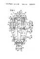
- FIG. 1is a top plan view showing a stretcher of the present invention in an open condition preparatory for use.
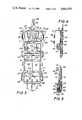
- FIG. 2is a bottom plan view showing the stretcher of FIG. 1.
- FIG. 3is a top plan view showing the stretcher in an operative condition, but absent a patient's body to facilitate understanding.
- FIG. 4is a partial longitudinal sectional view taken generally along the line 4--4 of FIG. 3.
- FIG. 5is a partial longitudinal sectional view taken generally along the line 5--5 of FIG. 3.
- FIG. 6is a transverse sectional view taken generally along the line 6--6 of FIG. 3.
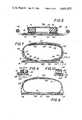
- FIG. 7is a transverse sectional view taken generally along the line 7--7 of FIG. 3.
- FIG. 8is a transverse sectional view taken generally along the line 8--8 of FIG. 3.
- FIG. 9is a partial sectional view in the correspondingly designated area of FIG. 7, but with the strap in its nonuse condition.
- FIG. 10is a sectional elevational view taken generally along the line 10--10 of FIG. 9.
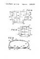
- FIG. 11is a partial top plan view similar to FIG. 3, but showing a slightly modified embodiment of the instant invention.
- FIG. 12a transverse sectional view taken generally along the line 12--12 of FIG. 11, but showing a stiffener board of less than maximum width.
- FIG. 13is a sectional view similar to FIG. 12, but illustrating constriction of the board receiving pocket closely about the board.
- FIG. 14is a partial top plan view similar to FIG. 1, but showing a slightly modified embodiment including an additional strap extending from laterally intermediate regions of the pocket for wrapping about a person's limbs.
- FIG. 15is a plan view similar to FIG. 3, but showing the embodiment of FIG. 14.
- FIG. 16is a transverse sectional view taken generally along the line 16--16 of FIG. 15.
- the stretcheris there generally designated 10 and includes an elongate generally flat pocket or sleeve 11.
- the pocket or sleeve 11may be fabricated of suitable flexible sheet material, including a pair of generally rectangular, substantially congruent, overlying inner and outer sheets 12 and 13, which sheets are seen as upper and lower in FIGS. 6-8.
- the upper sheet 12is secured along one end to the adjacent end of the lower sheet 13, as by securement means or stitching 15 extending laterally between opposite side edges of the sheets 12 and 13. Further, the sheets 12 and 13 are secured together along longitudinal side edges by suitable securing means or stitching, as at 16 and 17.
- the pocket or sleeve 11has one end closed, as by stitching or closure means 15 at one sleeve end 20, and has its opposite longitudinal or side edges closed, as at 21 and 22, each closed side extending the entire length of the sleeve.
- the opposite end of the sleeve 11, remote from the closed end 20,is open, as at 24, and provided on the end of the lower or outer sheet 13 with an extension or flap 25.
- the extension or flap 25is laterally coextensive with the pocket 11; and, there are provided on the flap 25 and adjacent end portion of sheet 12 a pair of complementary, detachably connectible, laterally extending strips or pieces of fastener fabric 26 and 27.
- a torso girding partgenerally designated 30 and essentially fabricated from a single piece of flexible sheet material extending transversely across and beyond opposite side edges 21 and 22 of the pocket 11.
- the torso girding part 30includes a medial, generally rectangular region 31 suitably secured by stitching 32 or other suitable securing means, to the upper surface of upper sheet 12. More particularly, the secured medial region 31 of torso girding part 30 is spaced laterally between the side edges 21 and 22 of the pocket 11, the securing means 32 being spaced inwardly from the side edges.
- the torso girding partincludes a pair of intermediate portions or panels 33 and 34, which are swingably or hingedly connected to respective side edges of the medial region 31, so as to be swingable upwardly away from the pocket 11. More specifically, the intermediate panels 33 and 34 are each swingably or hingedly connected, as by a respective flexible connection 35 and 36, to the adjacent side edge of medial panel 31; and, the panels 33 and 34 are advantageously stiffened or rigidified, as by securement thereto of stiffener means or padding, as at 37 and 38 best seen in FIG. 7.
- the stiffener elements or padding 37 and 38may be secured to the torso girding part 30 by respective covering sheets 39 and 40.
- each intermediate stiffened part 33 and 34there extends a flexible covering flap or sheet, as at 41 and 42.
- the torso girding part 30may include, as a single integral sheet, the medial portion 31, the intermediate portions 33 and 34 extending from opposite sides of the medial portion, and the outer end extensions or flaps 41 and 42 extending from respective intermediate portions 33 and 34.
- a rescueemay rest with his torso on the medial region 31 and the stiffened intermediate regions 33 and 34 swung upwardly to afford effective underarm support to the rescuee.
- the extension flaps or terminal portions 41 and 42 of the torso girding part 30are swung over the rescuee, in overlying relation with each other, and provided with detachable securing means, preferably in the form of fastener fabric strips, as at 43, extending longitudinally on the upper surface of extension 41, and 44 extending laterally on the inner surface of extension 42.
- the fastener fabric stripsare suitably secured to the extensions, as by stitching or otherwise, the outwardly facing fastener fabric strips 43 extending longitudinally of the pocket or sleeve 11, and the inwardly or downwardly facing fastener fabric strips 44 extending laterally or transversely of the pocket or sleeve.
- the extension 42is necessarily swung first to overly the rescuee, and the extension 41 subsequently swung to overly the rescuee and the extension 42. This places the fastener fabric strips in transversely extending, facing engagement and secured together to maintain the extensions in their overlying relationship.
- Additional fastener meansare provided for securing the torso girding part 30 in its torso girding relation, such as a plurality of belts or straps 48 and 50, which are suitably secured to and between the medial torso girding portion 31 and the adjacent portion of pocket sheet 12. That is, by suitable stitching, as at 32, intermediate portions of the several belts or straps 48, 50 are secured between the medial torso girding portion 31 and the nether region of pocket sheet 12; and, the belts or straps extend oppositely outwardly beyond the medial region free of the pocket for extension about the exterior of the wrapped torso girding part 30 with its extensions 41 and 42 overlying each other. Oppositely extending free ends of the straps 48 and 50 are provided with detachably connectible fastening elements or buckles, as at 51 and 53.
- binding stripsmay be provided or secured on the upper surface of pocket wall 12, as at 54 and 56, for releasable binding about the straps 48 and 50 when the latter are in a coiled, nonuse condition.
- the binding straps or strips 54 and 56may also be of fastener fabric, if desired.
- limb girding sheets or flaps 60 and 61are also secured to the upper or outer face of pocket wall 12, spaced between the torso girding part 30 and the open pocket end 24, are a pair of flexible limb girding sheets or flaps 60 and 61.
- the limb girding sheets or flapsare disposed in side by side spaced relation, each having its inner edge margin suitably secured, as by stitching, to the upper or outer wall 12 of pocket 11.
- the inner margin 62 of limb girding flap 60is secured to the exterior of pocket wall 12 at a location along and spaced inward from the pocket side edge 21, while the inner edge margin 63 of the limb girding flap 61 is suitably stitched or otherwise secured to the outer surface of pocket wall 12 along and spaced inward from the pocket side edge 22.
- the flaps 60 and 61are thus secured to the pocket only along their inner edges 62 and 63, the remainders thereof being free to swing about and overlie the limbs of a rescuee on the wall 12 of pocket 11.
- the limb girding flaps 60 and 61may taper in the direction toward the open pocket end 24, to accomodate to the decreasing proportions of a person and minimize bulk of the device.
- the flap 61In the storage condition, the flap 61 may be swung inward to overlie the laterally medial region of pocket wall 12, and flap 60 swung inwardly to overlie the flap 61.
- a pair of mating patches of fastener fabricmay be secured to the outer flap 60, as at 64, and to the wall 12, as at 65, to secure the flaps in the nonuse condition.
- a head rest area 67Intermediate the torso girding part 30 and the closed end 20 of the pocket 11, laterally medially between the pocket side edges 21 and 22, there is a head rest area 67.
- the fastener fabric pieces 68 and 69are generally elongate, and extend in parallelism with each other longitudinally of the pocket 11.
- An additional longitudinally extending strip of fastener fabric 70is secured to the pocket wall 12, spaced laterally between the pieces 68 and 69, and adjacent to the medial region 31 of the torso girding part 30.
- a pair of elongate cushions or cushioned bodies 71 and 72are connected together by a flexible tie member or strip 73 extending between adjacent ends of the cushions.
- the cushions 71 and 72may seat on and be detachably secured to the fabric fastener piece 68 and 69, with the flexible tie member 73 extending between the ends of the cushions adjacent to the closed end 20 of the pocket 11. This condition is shown in FIG. 3.
- a pair of straps 78 and 79may be secured to the pocket wall 12, say beneath the fastener fabric piece 68 and extending laterally outwardly therefrom to terminate in connector elements 80 and 81.
- Secured to the wall 12 beneath the fastener fabric piece 69 and extending laterally therefrommay be additional strap connector elements 82 and 83 for detachable connection to respective strap connector elements 80 and 81.
- the strap means 78 and 79is adapted to extend releasably over the cushion bodies 71 and 72 and across the head rest area 67, as seen in FIG. 3, for holding the cushions and a person's head in position on the pocket 11.
- the pocket or sleeve 11is provided adjacent to its open lower end 24 with a subpocket 85, see FIG. 5, defined between the lower end region 86 of wall 12 and a generally rectangular pocket sheet 87 interposed between the walls 12 and 13 and secured to the wall 12, as by transverse stitching 88 and longitudinal stitching 16 and 17 along the respective side edges 21 and 22 of the pocket 11.
- the subpocket 85is generally rectangular, laterally coextensive with the pocket or sleeve 11, and opens longitudinally outwardly of the sleeve 11 through the open sleeve end 24.
- Separable fastener meansmay be provided along the opening of the subpocket 85, such as separable fastener fabric strips 89 and 90.
- a generally flat neck support or cushion 91Removably positioned in the interior of closed pocket 85, as seen in FIG. 5, is a generally flat neck support or cushion 91.
- the cushion 91is seen in FIGS. 1 and 2 apart from the sleeve 11 exteriorly of the subpocket 85.
- the neck cushion 91may be generally rectangular and essentially flat for conforming engagement and storage in the subpocket 85, including generally rectangular opposite faces or sides 92 and 93, as seen in FIGS. 1 and 2, respectively.
- the longitudinal dimension or length of the cushion 91extends laterally or transversely of the pocket or sleeve 11, as does the longitudinal dimension or length of the subpocket 81 to conformably accomodate the neck cushion.
- a strip of fastener fabric 94Secured on one face or side 92 of the neck cushion 91, extending longitudinally therealong and spaced laterally medially between the side edges of the neck cushion is a strip of fastener fabric 94.
- an elongate strip of complementary fastener fabric 95On the other side or face 93 of the neck cushion 91 there is secured an elongate strip of complementary fastener fabric 95, also extending longitudinally coterminous with the cushion, laterally spaced medially between the longitudinal side edges thereof.
- the neck cushion 91will be self holding in any longitudinal rolled or coiled condition, such as tight, loose, etc.
- the neck cushion 91is illustrated rolled in FIG. 4, with one of the fastener fabric strips 94, 95 exteriorly of and exposed peripherally about the coil. It will there be observed that the coil 91 is seated on the fastener fabric piece 70 secured in the head rest region 67 of the sheet 12.
- the coiled neck rest cushionis securely, but detachably held in position beneath an occupant's neck.
- the neck support cushion 91may be removed from the head rest area 67 and uncoiled for reinsertion in the subpocket 85.
- a plurality of securement straps 97may be secured to the wall 13 of pocket 11 and extend longitudinally outwardly beyond the open end 24 and closure flap 25.
- Fastener elements 98are secured to the free ends of straps 97, and complementary fastener elements 99 are secured to the sheet 12 just inward of the open end 24.
- the complementary fastener elements 99are secured to the sheet 12 just inward of the end 24.
- the complementary fastener elements 98 and 99are detachably connectible together to secure the flap 25 in its closed condition against substantial forces.
- a rigid board 45 substantially congruent to the pocket 11may be inserted into the interior of the pocket through the open end 24 to substantially fully occupy the pocket, and may be secured therein both by closing of the flap 25 with adherence of the fabric fastener strips 26 and 27, and by securement of the detachable connectors 98 and 99 with the straps 97 adjusted tightly. If it is not desired to carry a full size board for use in the pocket 11, any smaller size board may be inserted therein to achieve the spine immobilizing effects.
- the pocket 11is adapted to effectively contain a standard backboard, a regular or bi-fold metal backboard, or a conventional scoop litter.
- the strap 101may extend transversely in the region of torso girding part 30, and the straps 102 and 103 extend transversely in the region of the limb girding flaps 60 and 61.
- the strap 101may have detachable connectors 104 at its opposite ends, while the strap 102 has detachable connectors 105 at its opposite ends, and the strap 103 has detachable connectors 106 at its opposite ends.
- the straps 101, 102 and 103with their ends connected, encompass both the pocket 11 and the torso and limb girding parts, so as to effectively secure the person of the occupant to a stiffener in the pocket 11.
- Binding straps 107, 108 and 109may be secured to the pocket wall 12, exteriorly thereof, for releasably binding the straps 101, 102 and 103, respectively, when the latter are in a coiled, storage condition.
- a pair of laterally extending lifting straps 110 and 111may extend across and be secured to the outer side of pocket wall 13, adjacent to opposite ends of the pocket 11, and may be provided with lifting eyes 112 and 113, respectively.
- An end lifting strap 114may be secured to the outer side of pocket wall 13, extending beyond the pocket end 20, and there provided with a lifting eye or ring 115.
- a plurality of hand holdssuch as a pair of opposite hand holds 116 extending from opposite sides of the pocket 11 adjacent to the pocket end 20, a pair of opposed hand holds 117 spaced medially between opposite pocket ends, and a pair of opposed hand holds 118 adjacent to the open pocket end 24.
- the hand holdsmay be advantageously fabricated of sturdy webbing, and extend entirely across and beyond opposite side edges of the pocket wall 13, being stitched or otherwise suitably secured thereto.
- the covering sheet 120In addition to the pocket sheets 12 and 13, there is another, also substantially congruent flexible covering sheet 120, secured about its peripheral margins to the pocket sheet 13 exteriorly thereof.
- the covering sheetthus protectively overlies and conceals the several straps 101, 102 and 103, 110, 111 and 114, and the webbing of hand holds 116, 117 and 118.
- the back of the stretcher, opposite to the surface carrying a rescuee,is thus substantially completely smooth to effectively prevent unintended hang-ups, or the like.
- FIGS. 11, 12 and 13there is shown a head rest area 67a adjacent to the closed pocket end 20a and spaced between the pocket side edges 21a and 22a.
- the fastener fabric pieces 68a and 69aare generally elongate, and extend in parallelism with each other longitudinally of the pocket 11.
- a pair of elongate cushions or cushioned bodies 71a and 72aare connected by a flexible tie member or strip 73a extending between adjacent ends of the cushions.
- the cushions 71 and 72may seat on and be detachably secured to the fabric fastener pieces 68a and 69a, with the flexible tie member 73a extending between the ends of the cushions adjacent to the closed end 20 of the pocket 11.
- the cushions 71a and 72aare of generally triangular or wedge shape in transverse cross section, being thicker or heavier on their inner sides facing toward each other, and tapering toward their outer edges away from each other.
- FIGS. 11-13there are preferably four straps 78a, corresponding to the two straps of the first described embodiment, each of which may be secured to the pocket wall 12a, say beneath the fastener fabric piece 68a and extend laterally outwardly therefrom to terminate in a connector element 80a.
- a connector element 80aSecured to the wall 12a beneath the fastener fabric piece 69a and extending laterally therefrom may be an additional strap connector element 82a for detachable connection to strap connector 80a.
- the straps 78aare thus adapted to extend releasably over the cushion bodies 71a and 72a for holding the cushions and a person's head in position on the pocket 11.
- An additional elongate flexible draw element or strap 76may extend transversely across and outwardly of the lower, outer pocket wall or sheet 13a, as between the latter and lower covering sheet 120a and extending laterally outwardly therebeyond as by strap end portions 77.
- the draw elements or straps 77may be unsecured to the pocket 11a, or may be tacked or secured, say at one location to the pocket so as to permit gathering of the pocket along the draw element.
- buckles 96Secured to the upper side of the pocket 11a, spaced inwardly from the pocket side edges 21a and 22a, as by a pair of straps 84, may be a respective pair of self tightening buckles 96.
- the buckles 96are each aligned with a respective end portion 77 of draw element 76, and the buckles are located laterally inwardly from respective pocket sides or edges 21a and 22a, so that the side edge portions of the pocket, may, under certain circumstance, be gathered up by tightly drawing the strap end portions 77.
- FIG. 13wherein a board 45a is received in the pocket 11a, which board is of less lateral dimension or width than the interior lateral dimension or width of the pocket 11a, as best seen in FIG. 12.
- a boardmay sometimes be used, either for convenience or necessity, and in such circumstances it may be desired to reduce the effective width of the pocket 11a to constrict the latter closely about the board. This is done by drawing up of the strap end portions 77, to the condition shown in FIG. 13, which condition is held by the buckles 96, until deliberately released.
- the draw element of FIGS. 11-13is in the head region of the pocket 11, so that the patient's head is held against relative movement with respect to the board.
- the draw elementmay, alternatively or additionally, be located at other regions of the pocket, say the torso region or the limb region.
- a pair of flexible limb girding sheets or flaps 60a and 61aare each secured, as along its inner edge margin, as at 62a and 63a, respectively, to the upper or outer wall 12a of the pocket 11a, at locations spaced inwardly from adjacent side edges 21a and 22a of the pocket.
- the flaps 60a and 61amay be substantially identical to the flaps 60 and 61 of the first described embodiment; and, there may be girding straps 102a and 103a cooperable with detachable connectors 105a and 106a in the same manner as straps 102 and 103, and connectors 105 and 106.
- FIGS. 14-16includes a girding strap 100 which may have its inner end secured to pocket 11a on the upper side thereof spaced inwardly from the pocket edges.
- a girding strap 100which may have its inner end secured to pocket 11a on the upper side thereof spaced inwardly from the pocket edges.
- the free end of strap 100may include a detachable buckle element 121; and, a complementary detachable buckle element 122 which may be carried by a strap portion 123 having its inner end 124 secured to the upper side 12a of the pocket 11a at a location adjacent to and spaced inward from the pocket side edge 21a.
- the strap 100 and strap portion 123may be a single integral strap, if desired, or complementary parts of cooperative strap means for extension about the limbs of a person occupying the stretcher. In such case it will be appreciated that the limbs are effectively restrained relative to the pocket and a received board, whether the board is of maximum width or less than maximum width.
- the device of the present inventionprovides an emergency stretcher which is extremely fast and easy to use, secure and safe even under difficult operating conditions, and which otherwise fully accomplishes its intended objects.
Landscapes
- Health & Medical Sciences (AREA)
- Life Sciences & Earth Sciences (AREA)
- Animal Behavior & Ethology (AREA)
- General Health & Medical Sciences (AREA)
- Public Health (AREA)
- Veterinary Medicine (AREA)
- Nursing (AREA)
- Orthopedics, Nursing, And Contraception (AREA)
Abstract
Description
______________________________________ U.S. PAT. NO. PATENTEE ______________________________________ 722,456 Reeves 2,279,694 Martinson 2,350,573 Smith et al. 2,361,328 Springer 2,489,828 Springer 2,788,530 Ferguson 2,899,692 Finken 3,158,875 Fletcher 3,343,180 Lothschuetz 3,566,422 Klippel 4,034,748 Winner 4,124,908 Burns et al. 4,211,218 Kendrick 4,297,994 Bashaw 4,301,791 Franco 4,347,635 Eisenhauer ______________________________________
Claims (12)
Priority Applications (1)
| Application Number | Priority Date | Filing Date | Title |
|---|---|---|---|
| US06/731,298US4601075A (en) | 1984-01-26 | 1985-05-07 | Emergency stretcher |
Applications Claiming Priority (2)
| Application Number | Priority Date | Filing Date | Title |
|---|---|---|---|
| US57404084A | 1984-01-26 | 1984-01-26 | |
| US06/731,298US4601075A (en) | 1984-01-26 | 1985-05-07 | Emergency stretcher |
Related Parent Applications (1)
| Application Number | Title | Priority Date | Filing Date |
|---|---|---|---|
| US57404084AContinuation-In-Part | 1984-01-26 | 1984-01-26 |
Publications (1)
| Publication Number | Publication Date |
|---|---|
| US4601075Atrue US4601075A (en) | 1986-07-22 |
Family
ID=27076271
Family Applications (1)
| Application Number | Title | Priority Date | Filing Date |
|---|---|---|---|
| US06/731,298Expired - LifetimeUS4601075A (en) | 1984-01-26 | 1985-05-07 | Emergency stretcher |
Country Status (1)
| Country | Link |
|---|---|
| US (1) | US4601075A (en) |
Cited By (66)
| Publication number | Priority date | Publication date | Assignee | Title |
|---|---|---|---|---|
| US4665908A (en)* | 1985-06-11 | 1987-05-19 | Calkin Carston R | Extrication and spinal restraint device |
| US4742821A (en)* | 1986-01-29 | 1988-05-10 | Wootan Gerald D | Patient restraint apparatus |
| US4776327A (en)* | 1985-08-09 | 1988-10-11 | Millar Mitchell & Co. Pty. Limited | Splint device |
| EP0301614A1 (en)* | 1987-06-30 | 1989-02-01 | Felix-Hoogendijk B.V. | Rescue stretcher |
| US4970739A (en)* | 1989-12-15 | 1990-11-20 | Bradford John G | Stretcher |
| US4979520A (en)* | 1987-12-21 | 1990-12-25 | Boone Jr Robert L | Pediatric device for immobilizing injured infant utilizing a standard size backboard |
| US5014724A (en)* | 1989-05-01 | 1991-05-14 | Miller Larry C | Pediatric immobilization device |
| US5014374A (en)* | 1989-02-24 | 1991-05-14 | Williams Gary R | Restraint stretcher |
| US5048134A (en)* | 1989-04-21 | 1991-09-17 | Dennill Wayne R | Restraining device |
| US5058575A (en)* | 1991-01-04 | 1991-10-22 | Hartwell Medical Corporation | Splint device |
| WO1991018576A1 (en)* | 1990-05-29 | 1991-12-12 | Wendy Jane Murphy | Patient evacuation envelope |
| US5121514A (en)* | 1990-12-10 | 1992-06-16 | Lifeport, Inc. | Emergency support device with flexible polyethylene sheet |
| US5154186A (en)* | 1990-04-12 | 1992-10-13 | Laurin Frederick J | Spinal restraint |
| US5161275A (en)* | 1992-03-20 | 1992-11-10 | Safety Quest, Inc. | Vehicle seat liner to facilitate extraction of an injured driver |
| US5249321A (en)* | 1990-08-28 | 1993-10-05 | Graf Jorg W | Evacuation or rescue device for a non-ambulatory person |
| US5435323A (en)* | 1994-03-10 | 1995-07-25 | Rudy; Walter R. | Device and method for securing patient to trauma board |
| WO1995033430A1 (en)* | 1994-06-03 | 1995-12-14 | Tarpaulin Ky | Stretcher |
| US5699568A (en)* | 1996-05-13 | 1997-12-23 | Couldridge; Paul R. | Stretcher for immobilizing a patient or casualty |
| US6065165A (en)* | 1997-08-22 | 2000-05-23 | Hill-Rom, Inc. | Prone patient apparatus |
| US6135114A (en)* | 1998-03-11 | 2000-10-24 | Duane R. Elliott | Vagabond restraint system |
| US6170486B1 (en)* | 1998-04-30 | 2001-01-09 | Steven T. Islava | Head immobilizer |
| US6341393B1 (en) | 1995-09-13 | 2002-01-29 | Ergodyne Corporation | Patient transfer and repositioning system |
| US20030126683A1 (en)* | 1998-06-26 | 2003-07-10 | Hill-Rom Services, Inc. | Hospital bed |
| US20040088794A1 (en)* | 2002-09-10 | 2004-05-13 | Calkin Carston R. | Emergency drag stretcher |
| US6817363B2 (en) | 2000-07-14 | 2004-11-16 | Hill-Rom Services, Inc. | Pulmonary therapy apparatus |
| US20040226091A1 (en)* | 1997-08-08 | 2004-11-18 | Hill-Rom Services, Inc. | Hospital bed |
| US20040244114A1 (en)* | 2001-09-12 | 2004-12-09 | Robinette Lydia Marie | Pediatric immobilizer |
| US20060137097A1 (en)* | 2004-11-24 | 2006-06-29 | Grant Frost | Rescue device |
| WO2006116811A1 (en)* | 2005-05-02 | 2006-11-09 | Martin Richardson | A pelvic brace and collapsible stretcher |
| US7137160B2 (en) | 1999-04-21 | 2006-11-21 | Hill-Rom Services, Inc. | Proning bed |
| US20080148482A1 (en)* | 2006-12-20 | 2008-06-26 | Rebekah Gonzalez | Infant/toddler carrying apparatus |
| US20090133702A1 (en)* | 2007-11-26 | 2009-05-28 | Mao-Kuan Chang | Medical Spine Board |
| US20090313754A1 (en)* | 2006-07-06 | 2009-12-24 | Smoor Johannes Petrus Cornelis | Evacuation Sheet |
| US20100275377A1 (en)* | 2009-05-04 | 2010-11-04 | Tamra West | Operating table patient positioner and method |
| AU2006243818B2 (en)* | 2005-05-02 | 2011-03-03 | Martin Richardson | A pelvic brace and collapsible stretcher |
| US20110179572A1 (en)* | 2010-01-25 | 2011-07-28 | Marion Mohr | Stretcher pad with child restraint system |
| US20110185504A1 (en)* | 2010-02-04 | 2011-08-04 | Christopher Kenalty | Evacuation sled for non-ambulatory patients |
| US20110219546A1 (en)* | 2009-05-04 | 2011-09-15 | Tamra West | Operating table patient positioner and method |
| US20120255124A1 (en)* | 2009-05-04 | 2012-10-11 | Tamra West | Operating table patient positioner and method |
| US8302610B1 (en)* | 2009-11-23 | 2012-11-06 | Larson Donald O | Spine immobilizer with removable straps |
| US20130276235A1 (en)* | 2012-04-19 | 2013-10-24 | Christopher Kenalty | Roll up evacuation mattress |
| USD693741S1 (en) | 2012-03-28 | 2013-11-19 | Allen R. Carrier | Rapid extrication device |
| US8677530B2 (en) | 2012-08-21 | 2014-03-25 | Skedco, Inc. | Rescue stretcher with securement straps |
| CN103705349A (en)* | 2013-01-12 | 2014-04-09 | 王必生 | Stretcher type medical translocation bed sheet |
| EP2719365A1 (en)* | 2012-10-12 | 2014-04-16 | Samarit Medical AG | Device for turning a patient |
| US20140224846A1 (en)* | 2013-02-12 | 2014-08-14 | Hayley MULLINS | Baby support |
| US20140366271A1 (en)* | 2013-06-18 | 2014-12-18 | Covidien Lp | Patient Positioning System |
| US20150283006A1 (en)* | 2014-04-08 | 2015-10-08 | Wilber Akins | Transport devices and methods of use for transport of immobilized persons |
| US9237963B2 (en) | 2012-03-29 | 2016-01-19 | Allen Carrier | Rapid extrication device |
| US9827152B1 (en) | 2016-10-28 | 2017-11-28 | Skedco, Inc. | Rescue harness with protective drag sheet |
| US9833370B1 (en)* | 2014-03-18 | 2017-12-05 | MedPro US Inc. | Mattress with patient restraint stored inside |
| EP3195840A4 (en)* | 2014-11-18 | 2018-05-30 | Esquina Iglesias, Raúl | Device for immobilising injured children in a chair for transporting said children in vehicles by road, and instructions for use |
| US20190046380A1 (en)* | 2017-08-10 | 2019-02-14 | Maaz Meah | Surgical positioning system |
| USD841259S1 (en) | 2016-10-28 | 2019-02-19 | Skedco, Inc. | Rescue drag sheet |
| US10363177B2 (en)* | 2013-07-15 | 2019-07-30 | Fibrelight Developments Limited | Folding stretcher |
| WO2019165301A1 (en)* | 2018-02-23 | 2019-08-29 | Skedco, Inc. | Rescue stretcher with integrated harness |
| US10518116B2 (en) | 2014-09-11 | 2019-12-31 | Skedco, Inc. | Patient evacuation and recovery hauling system |
| US10932963B2 (en) | 2016-12-28 | 2021-03-02 | Christopher Kenalty | Rapid evacuation sled for patients and victims |
| US20210169713A1 (en)* | 2016-12-28 | 2021-06-10 | Christopher Kenalty | Rapid evacuation sled for patients and victims |
| US11071660B1 (en)* | 2020-11-26 | 2021-07-27 | Seok Ran Yeom | Emergency medical mat for safe movement in case of disaster |
| US11344457B2 (en) | 2019-07-17 | 2022-05-31 | Skedco, Inc. | Rescue stretcher |
| US11504284B2 (en)* | 2018-10-04 | 2022-11-22 | Northwall S.R.L. | Spinal immobilization table |
| US11744749B2 (en) | 2016-12-28 | 2023-09-05 | Christopher Kenalty | Rapid evacuation sled for patients and victims |
| US20240000639A1 (en)* | 2022-06-30 | 2024-01-04 | Margaret Ann Lockridge | Foldable Survival Stretcher |
| US12208043B2 (en) | 2023-01-25 | 2025-01-28 | McNiven Patents, LLC | Apparatus, system, and method for lifting a patient |
| US12364634B2 (en) | 2022-09-09 | 2025-07-22 | Skedco, Inc. | Rescue stretcher |
Citations (8)
| Publication number | Priority date | Publication date | Assignee | Title |
|---|---|---|---|---|
| US2489828A (en)* | 1944-10-10 | 1949-11-29 | Kenneth F Springer | Litter |
| US2788530A (en)* | 1952-02-04 | 1957-04-16 | Jerome A Rooney | Rescue apparatus |
| US3158875A (en)* | 1962-09-05 | 1964-12-01 | Citizens Nat Bank Of Lubbock | Invalid stretcher |
| US4034748A (en)* | 1975-10-28 | 1977-07-12 | Winner Stephen E | Spinal restraint device |
| US4124908A (en)* | 1977-10-06 | 1978-11-14 | Burns Oliver E | Rescue and transportation device |
| US4211218A (en)* | 1978-08-14 | 1980-07-08 | Kendrick Richard L | Spinal restraint device |
| US4297994A (en)* | 1979-11-27 | 1981-11-03 | Bashaw Robert W | Cervical immobilizer |
| US4506664A (en)* | 1983-03-30 | 1985-03-26 | Brault Richard A | Spineboard |
- 1985
- 1985-05-07USUS06/731,298patent/US4601075A/ennot_activeExpired - Lifetime
Patent Citations (8)
| Publication number | Priority date | Publication date | Assignee | Title |
|---|---|---|---|---|
| US2489828A (en)* | 1944-10-10 | 1949-11-29 | Kenneth F Springer | Litter |
| US2788530A (en)* | 1952-02-04 | 1957-04-16 | Jerome A Rooney | Rescue apparatus |
| US3158875A (en)* | 1962-09-05 | 1964-12-01 | Citizens Nat Bank Of Lubbock | Invalid stretcher |
| US4034748A (en)* | 1975-10-28 | 1977-07-12 | Winner Stephen E | Spinal restraint device |
| US4124908A (en)* | 1977-10-06 | 1978-11-14 | Burns Oliver E | Rescue and transportation device |
| US4211218A (en)* | 1978-08-14 | 1980-07-08 | Kendrick Richard L | Spinal restraint device |
| US4297994A (en)* | 1979-11-27 | 1981-11-03 | Bashaw Robert W | Cervical immobilizer |
| US4506664A (en)* | 1983-03-30 | 1985-03-26 | Brault Richard A | Spineboard |
Cited By (94)
| Publication number | Priority date | Publication date | Assignee | Title |
|---|---|---|---|---|
| US4665908A (en)* | 1985-06-11 | 1987-05-19 | Calkin Carston R | Extrication and spinal restraint device |
| US4776327A (en)* | 1985-08-09 | 1988-10-11 | Millar Mitchell & Co. Pty. Limited | Splint device |
| US4742821A (en)* | 1986-01-29 | 1988-05-10 | Wootan Gerald D | Patient restraint apparatus |
| EP0301614A1 (en)* | 1987-06-30 | 1989-02-01 | Felix-Hoogendijk B.V. | Rescue stretcher |
| US4979520A (en)* | 1987-12-21 | 1990-12-25 | Boone Jr Robert L | Pediatric device for immobilizing injured infant utilizing a standard size backboard |
| US5014374A (en)* | 1989-02-24 | 1991-05-14 | Williams Gary R | Restraint stretcher |
| US5048134A (en)* | 1989-04-21 | 1991-09-17 | Dennill Wayne R | Restraining device |
| US5014724A (en)* | 1989-05-01 | 1991-05-14 | Miller Larry C | Pediatric immobilization device |
| US4970739A (en)* | 1989-12-15 | 1990-11-20 | Bradford John G | Stretcher |
| US5154186A (en)* | 1990-04-12 | 1992-10-13 | Laurin Frederick J | Spinal restraint |
| WO1991018576A1 (en)* | 1990-05-29 | 1991-12-12 | Wendy Jane Murphy | Patient evacuation envelope |
| US5249321A (en)* | 1990-08-28 | 1993-10-05 | Graf Jorg W | Evacuation or rescue device for a non-ambulatory person |
| US5121514A (en)* | 1990-12-10 | 1992-06-16 | Lifeport, Inc. | Emergency support device with flexible polyethylene sheet |
| WO1992010155A1 (en)* | 1990-12-10 | 1992-06-25 | Lifeport, Inc. | Emergency support device |
| US5058575A (en)* | 1991-01-04 | 1991-10-22 | Hartwell Medical Corporation | Splint device |
| US5161275A (en)* | 1992-03-20 | 1992-11-10 | Safety Quest, Inc. | Vehicle seat liner to facilitate extraction of an injured driver |
| US5435323A (en)* | 1994-03-10 | 1995-07-25 | Rudy; Walter R. | Device and method for securing patient to trauma board |
| WO1995033430A1 (en)* | 1994-06-03 | 1995-12-14 | Tarpaulin Ky | Stretcher |
| US5729850A (en)* | 1994-06-03 | 1998-03-24 | Tarpaulin Ky | Stretcher |
| US6341393B1 (en) | 1995-09-13 | 2002-01-29 | Ergodyne Corporation | Patient transfer and repositioning system |
| US5699568A (en)* | 1996-05-13 | 1997-12-23 | Couldridge; Paul R. | Stretcher for immobilizing a patient or casualty |
| US20040226091A1 (en)* | 1997-08-08 | 2004-11-18 | Hill-Rom Services, Inc. | Hospital bed |
| US6065165A (en)* | 1997-08-22 | 2000-05-23 | Hill-Rom, Inc. | Prone patient apparatus |
| US6135114A (en)* | 1998-03-11 | 2000-10-24 | Duane R. Elliott | Vagabond restraint system |
| US6170486B1 (en)* | 1998-04-30 | 2001-01-09 | Steven T. Islava | Head immobilizer |
| US20030126683A1 (en)* | 1998-06-26 | 2003-07-10 | Hill-Rom Services, Inc. | Hospital bed |
| US6862759B2 (en) | 1998-06-26 | 2005-03-08 | Hill-Rom Services, Inc. | Hospital bed |
| US7137160B2 (en) | 1999-04-21 | 2006-11-21 | Hill-Rom Services, Inc. | Proning bed |
| US6817363B2 (en) | 2000-07-14 | 2004-11-16 | Hill-Rom Services, Inc. | Pulmonary therapy apparatus |
| US7931607B2 (en) | 2000-07-14 | 2011-04-26 | Hill-Rom Services, Inc. | Pulmonary therapy apparatus |
| US7343916B2 (en) | 2000-07-14 | 2008-03-18 | Hill-Rom Services, Inc. | Pulmonary therapy apparatus |
| US20040244114A1 (en)* | 2001-09-12 | 2004-12-09 | Robinette Lydia Marie | Pediatric immobilizer |
| US6966087B2 (en)* | 2001-09-12 | 2005-11-22 | Lydia Marie Robinette | Pediatric immobilizer |
| US6871368B2 (en)* | 2002-09-10 | 2005-03-29 | Carston R. Calkin | Emergency drag stretcher |
| US20040088794A1 (en)* | 2002-09-10 | 2004-05-13 | Calkin Carston R. | Emergency drag stretcher |
| US20060137097A1 (en)* | 2004-11-24 | 2006-06-29 | Grant Frost | Rescue device |
| US7610641B2 (en)* | 2004-11-24 | 2009-11-03 | Grant Frost | Rescue device |
| GB2440098A (en)* | 2005-05-02 | 2008-01-16 | Martin Richardson | A pelvic brace and collapsible stretcher |
| AU2006243818B2 (en)* | 2005-05-02 | 2011-03-03 | Martin Richardson | A pelvic brace and collapsible stretcher |
| GB2440098B (en)* | 2005-05-02 | 2010-09-08 | Martin Richardson | A pelvic brace and collapsible stretcher |
| WO2006116811A1 (en)* | 2005-05-02 | 2006-11-09 | Martin Richardson | A pelvic brace and collapsible stretcher |
| US20090313754A1 (en)* | 2006-07-06 | 2009-12-24 | Smoor Johannes Petrus Cornelis | Evacuation Sheet |
| US7444695B2 (en)* | 2006-12-20 | 2008-11-04 | Rebekah Gonzalez | Infant/toddler carrying apparatus |
| US20080148482A1 (en)* | 2006-12-20 | 2008-06-26 | Rebekah Gonzalez | Infant/toddler carrying apparatus |
| US20090133702A1 (en)* | 2007-11-26 | 2009-05-28 | Mao-Kuan Chang | Medical Spine Board |
| US20100275377A1 (en)* | 2009-05-04 | 2010-11-04 | Tamra West | Operating table patient positioner and method |
| US8539623B2 (en)* | 2009-05-04 | 2013-09-24 | Tamra West | Operating table patient positioner and method |
| US8539622B2 (en)* | 2009-05-04 | 2013-09-24 | Tamra West | Operating table patient positioner and method |
| US20110219546A1 (en)* | 2009-05-04 | 2011-09-15 | Tamra West | Operating table patient positioner and method |
| US20120255124A1 (en)* | 2009-05-04 | 2012-10-11 | Tamra West | Operating table patient positioner and method |
| US8539621B2 (en)* | 2009-05-04 | 2013-09-24 | Tamra West | Operating table patient positioner and method |
| US8302610B1 (en)* | 2009-11-23 | 2012-11-06 | Larson Donald O | Spine immobilizer with removable straps |
| US20110179572A1 (en)* | 2010-01-25 | 2011-07-28 | Marion Mohr | Stretcher pad with child restraint system |
| US8667629B2 (en)* | 2010-01-25 | 2014-03-11 | Marion Mohr | Stretcher pad with child restraint system |
| US20110185504A1 (en)* | 2010-02-04 | 2011-08-04 | Christopher Kenalty | Evacuation sled for non-ambulatory patients |
| US8365326B2 (en) | 2010-02-04 | 2013-02-05 | Christopher Kenalty | Evacuation sled for non-ambulatory patients |
| USD693741S1 (en) | 2012-03-28 | 2013-11-19 | Allen R. Carrier | Rapid extrication device |
| US9237963B2 (en) | 2012-03-29 | 2016-01-19 | Allen Carrier | Rapid extrication device |
| US8938828B2 (en)* | 2012-04-19 | 2015-01-27 | Christopher Kenalty | Roll up evacuation mattress |
| US20130276235A1 (en)* | 2012-04-19 | 2013-10-24 | Christopher Kenalty | Roll up evacuation mattress |
| US8677530B2 (en) | 2012-08-21 | 2014-03-25 | Skedco, Inc. | Rescue stretcher with securement straps |
| EP2719365A1 (en)* | 2012-10-12 | 2014-04-16 | Samarit Medical AG | Device for turning a patient |
| CN103705349A (en)* | 2013-01-12 | 2014-04-09 | 王必生 | Stretcher type medical translocation bed sheet |
| US9289076B2 (en)* | 2013-02-12 | 2016-03-22 | Hayley Mullins | Baby support |
| US20150150385A1 (en)* | 2013-02-12 | 2015-06-04 | Hayley MULLINS | Baby support |
| US20140224846A1 (en)* | 2013-02-12 | 2014-08-14 | Hayley MULLINS | Baby support |
| US9339119B2 (en)* | 2013-02-12 | 2016-05-17 | Hayley MULLINS | Baby support |
| US9603466B2 (en)* | 2013-02-12 | 2017-03-28 | 2373945 Ontario Inc. | Baby support |
| US10213030B2 (en) | 2013-02-12 | 2019-02-26 | S2S Innovations Inc. | Baby support |
| US20140366271A1 (en)* | 2013-06-18 | 2014-12-18 | Covidien Lp | Patient Positioning System |
| US9375343B2 (en)* | 2013-06-18 | 2016-06-28 | Covidien Lp | Patient positioning system |
| US12115096B2 (en) | 2013-06-18 | 2024-10-15 | Kpr U.S., Llc | Patient positioning system |
| US10363177B2 (en)* | 2013-07-15 | 2019-07-30 | Fibrelight Developments Limited | Folding stretcher |
| US9833370B1 (en)* | 2014-03-18 | 2017-12-05 | MedPro US Inc. | Mattress with patient restraint stored inside |
| US20150283006A1 (en)* | 2014-04-08 | 2015-10-08 | Wilber Akins | Transport devices and methods of use for transport of immobilized persons |
| US10518116B2 (en) | 2014-09-11 | 2019-12-31 | Skedco, Inc. | Patient evacuation and recovery hauling system |
| EP3195840A4 (en)* | 2014-11-18 | 2018-05-30 | Esquina Iglesias, Raúl | Device for immobilising injured children in a chair for transporting said children in vehicles by road, and instructions for use |
| USD841259S1 (en) | 2016-10-28 | 2019-02-19 | Skedco, Inc. | Rescue drag sheet |
| US9827152B1 (en) | 2016-10-28 | 2017-11-28 | Skedco, Inc. | Rescue harness with protective drag sheet |
| US11911318B2 (en)* | 2016-12-28 | 2024-02-27 | Christopher Kenalty | Rapid evacuation sled for patients and victims |
| US11744749B2 (en) | 2016-12-28 | 2023-09-05 | Christopher Kenalty | Rapid evacuation sled for patients and victims |
| US20210169713A1 (en)* | 2016-12-28 | 2021-06-10 | Christopher Kenalty | Rapid evacuation sled for patients and victims |
| US10932963B2 (en) | 2016-12-28 | 2021-03-02 | Christopher Kenalty | Rapid evacuation sled for patients and victims |
| US20190046380A1 (en)* | 2017-08-10 | 2019-02-14 | Maaz Meah | Surgical positioning system |
| US11701281B2 (en)* | 2017-08-10 | 2023-07-18 | Maaz Meah | Surgical positioning system |
| US11311430B2 (en) | 2018-02-23 | 2022-04-26 | Skedco, Inc. | Rescue stretcher with integrated harness |
| WO2019165301A1 (en)* | 2018-02-23 | 2019-08-29 | Skedco, Inc. | Rescue stretcher with integrated harness |
| US11504284B2 (en)* | 2018-10-04 | 2022-11-22 | Northwall S.R.L. | Spinal immobilization table |
| US11344457B2 (en) | 2019-07-17 | 2022-05-31 | Skedco, Inc. | Rescue stretcher |
| US11071660B1 (en)* | 2020-11-26 | 2021-07-27 | Seok Ran Yeom | Emergency medical mat for safe movement in case of disaster |
| US20240000639A1 (en)* | 2022-06-30 | 2024-01-04 | Margaret Ann Lockridge | Foldable Survival Stretcher |
| US11938062B2 (en)* | 2022-06-30 | 2024-03-26 | Margaret Ann Lockridge | Foldable survival stretcher |
| US12364634B2 (en) | 2022-09-09 | 2025-07-22 | Skedco, Inc. | Rescue stretcher |
| US12208043B2 (en) | 2023-01-25 | 2025-01-28 | McNiven Patents, LLC | Apparatus, system, and method for lifting a patient |
Similar Documents
| Publication | Publication Date | Title |
|---|---|---|
| US4601075A (en) | Emergency stretcher | |
| US4124908A (en) | Rescue and transportation device | |
| CA1149251A (en) | Spinal restraint device | |
| US4580555A (en) | Portable pelvic and leg splint | |
| US4422454A (en) | Emergency extrication appliance | |
| US4679260A (en) | Flexible stretcher device | |
| US4881684A (en) | Wrapper for articles with improved securing arrangement | |
| US4204529A (en) | Cervical collar apparatus | |
| US4665908A (en) | Extrication and spinal restraint device | |
| US5243724A (en) | Multi-purpose baby wrap | |
| US4593788A (en) | Rescue apparatus | |
| US4922860A (en) | Child or disabled person training harness | |
| US5399151A (en) | Lifting belt and method | |
| US5056869A (en) | Restraining harness to hold child in highchair | |
| US6061853A (en) | Patient carrier/rescue stretcher | |
| US5944016A (en) | Adjustable, collapsible head immobilizer | |
| US5730340A (en) | Fanny pack with child's toy retaining assembly | |
| US4117840A (en) | Pediatric restraint garment | |
| US5211185A (en) | Head immobilizer | |
| US6227201B1 (en) | Immobilization backboard and blank for forming a backboard | |
| US4934357A (en) | Jaw support bandage | |
| US5685466A (en) | Multifunctional safety infant carrying bag structure | |
| US5792083A (en) | Arm sling | |
| US5787529A (en) | Rescue carrier device | |
| WO2000074517A1 (en) | Backpack having a modular frame |
Legal Events
| Date | Code | Title | Description |
|---|---|---|---|
| STCF | Information on status: patent grant | Free format text:PATENTED CASE | |
| FEPP | Fee payment procedure | Free format text:PAT HLDR NO LONGER CLAIMS SMALL ENT STAT AS INDIV INVENTOR (ORIGINAL EVENT CODE: LSM1); ENTITY STATUS OF PATENT OWNER: SMALL ENTITY | |
| FPAY | Fee payment | Year of fee payment:4 | |
| SULP | Surcharge for late payment | ||
| AS | Assignment | Owner name:TANGLEWOOD HOLDINGS, INC., MARYLAND Free format text:ASSIGNMENT OF ASSIGNORS INTEREST.;ASSIGNOR:SMITH, J. RUDY;REEL/FRAME:006357/0340 Effective date:19921201 Owner name:FREDERICKTOWN BANK & TRUST CO., MARYLAND Free format text:ASSIGNMENT OF ASSIGNORS INTEREST.;ASSIGNOR:TANGLEWOOD HOLDINGS, INC.;REEL/FRAME:006348/0774 Effective date:19921201 | |
| FEPP | Fee payment procedure | Free format text:PAYOR NUMBER ASSIGNED (ORIGINAL EVENT CODE: ASPN); ENTITY STATUS OF PATENT OWNER: SMALL ENTITY Free format text:PAT HOLDER CLAIMS SMALL ENTITY STATUS - SMALL BUSINESS (ORIGINAL EVENT CODE: SM02); ENTITY STATUS OF PATENT OWNER: SMALL ENTITY | |
| REMI | Maintenance fee reminder mailed | ||
| FPAY | Fee payment | Year of fee payment:8 | |
| SULP | Surcharge for late payment | ||
| AS | Assignment | Owner name:SMITH, J. RUDY, NEW JERSEY Free format text:COLLATERAL ASSIGNMENT;ASSIGNOR:TANGLEWOOD HOLDINGS, INC.;REEL/FRAME:006969/0646 Effective date:19921201 | |
| FPAY | Fee payment | Year of fee payment:12 | |
| AS | Assignment | Owner name:STOLBERG PARTNERS, NEW YORK Free format text:SECURITY INTEREST;ASSIGNOR:REEVES MANUFACTURING, INC.;REEL/FRAME:009396/0607 Effective date:19980821 Owner name:TANGLEWOOD HOLDINGS, INC., MARYLAND Free format text:CANCELLATION OF COLLATERAL ASSIGNMENT;ASSIGNOR:SMITH, J. RUDY;REEL/FRAME:009396/0605 Effective date:19980816 Owner name:REEVES MANUFACTURING, INC., MARYLAND Free format text:CHANGE OF NAME;ASSIGNOR:TANGLEWOOD HOLDINGS;REEL/FRAME:009396/0577 Effective date:19960802 Owner name:TANGLEWOOD HOLDINGS, INC., MARYLAND Free format text:CANCELLATION OF COLLATERAL ASSIGNMENT;ASSIGNOR:FREDRICKTOWN BANK & TRUST CO.;REEL/FRAME:009396/0603 Effective date:19980820 | |
| AS | Assignment | Owner name:RICHARDSON, PATRICK J., MARYLAND Free format text:TERMINATION OF SECURITY AGREEMENT;ASSIGNOR:STOLBERG PARTNERS, LP;REEL/FRAME:010327/0444 Effective date:19990811 Owner name:REEVES MANUFACTURING, INC., MARYLAND Free format text:TERMINATION OF SECURITY AGREEMENT;ASSIGNOR:STOLBERG PARTNERS, LP;REEL/FRAME:010327/0444 Effective date:19990811 |