US4601037A - Pulsed laser system - Google Patents
Pulsed laser systemDownload PDFInfo
- Publication number
- US4601037A US4601037AUS06/620,345US62034584AUS4601037AUS 4601037 AUS4601037 AUS 4601037AUS 62034584 AUS62034584 AUS 62034584AUS 4601037 AUS4601037 AUS 4601037A
- Authority
- US
- United States
- Prior art keywords
- laser
- pulse width
- pulse
- repetition rate
- power
- Prior art date
- Legal status (The legal status is an assumption and is not a legal conclusion. Google has not performed a legal analysis and makes no representation as to the accuracy of the status listed.)
- Expired - Fee Related
Links
- 230000004044responseEffects0.000claimsabstractdescription9
- 230000000737periodic effectEffects0.000claimsdescription2
- 230000005855radiationEffects0.000claimsdescription2
- 230000003213activating effectEffects0.000claims1
- 238000011282treatmentMethods0.000abstractdescription23
- 238000000034methodMethods0.000abstractdescription17
- 230000000994depressogenic effectEffects0.000abstractdescription8
- 238000010304firingMethods0.000abstractdescription6
- 230000015271coagulationEffects0.000description15
- 238000005345coagulationMethods0.000description15
- 238000004804windingMethods0.000description13
- XKRFYHLGVUSROY-UHFFFAOYSA-NArgonChemical compound[Ar]XKRFYHLGVUSROY-UHFFFAOYSA-N0.000description10
- 238000010586diagramMethods0.000description9
- 229910052786argonInorganic materials0.000description5
- 239000007789gasSubstances0.000description5
- 230000001052transient effectEffects0.000description4
- 239000003990capacitorSubstances0.000description3
- 230000009471actionEffects0.000description2
- 230000001186cumulative effectEffects0.000description2
- 230000002207retinal effectEffects0.000description2
- 230000000630rising effectEffects0.000description2
- 230000001960triggered effectEffects0.000description2
- XEEYBQQBJWHFJM-UHFFFAOYSA-NIronChemical group[Fe]XEEYBQQBJWHFJM-UHFFFAOYSA-N0.000description1
- 230000008901benefitEffects0.000description1
- 239000003086colorantSubstances0.000description1
- 230000008878couplingEffects0.000description1
- 238000010168coupling processMethods0.000description1
- 238000005859coupling reactionMethods0.000description1
- 230000007423decreaseEffects0.000description1
- 230000000881depressing effectEffects0.000description1
- 230000000694effectsEffects0.000description1
- 231100000040eye damageToxicity0.000description1
- 238000005286illuminationMethods0.000description1
- 238000002955isolationMethods0.000description1
- 229910052743kryptonInorganic materials0.000description1
- DNNSSWSSYDEUBZ-UHFFFAOYSA-Nkrypton atomChemical compound[Kr]DNNSSWSSYDEUBZ-UHFFFAOYSA-N0.000description1
- 230000037361pathwayEffects0.000description1
- 230000000649photocoagulationEffects0.000description1
- 230000008569processEffects0.000description1
- 238000009738saturatingMethods0.000description1
- 230000001225therapeutic effectEffects0.000description1
- 238000003079width controlMethods0.000description1
Images


Classifications
- A—HUMAN NECESSITIES
- A61—MEDICAL OR VETERINARY SCIENCE; HYGIENE
- A61F—FILTERS IMPLANTABLE INTO BLOOD VESSELS; PROSTHESES; DEVICES PROVIDING PATENCY TO, OR PREVENTING COLLAPSING OF, TUBULAR STRUCTURES OF THE BODY, e.g. STENTS; ORTHOPAEDIC, NURSING OR CONTRACEPTIVE DEVICES; FOMENTATION; TREATMENT OR PROTECTION OF EYES OR EARS; BANDAGES, DRESSINGS OR ABSORBENT PADS; FIRST-AID KITS
- A61F9/00—Methods or devices for treatment of the eyes; Devices for putting in contact-lenses; Devices to correct squinting; Apparatus to guide the blind; Protective devices for the eyes, carried on the body or in the hand
- A61F9/007—Methods or devices for eye surgery
- A61F9/008—Methods or devices for eye surgery using laser
- A61F9/00821—Methods or devices for eye surgery using laser for coagulation
- H—ELECTRICITY
- H01—ELECTRIC ELEMENTS
- H01S—DEVICES USING THE PROCESS OF LIGHT AMPLIFICATION BY STIMULATED EMISSION OF RADIATION [LASER] TO AMPLIFY OR GENERATE LIGHT; DEVICES USING STIMULATED EMISSION OF ELECTROMAGNETIC RADIATION IN WAVE RANGES OTHER THAN OPTICAL
- H01S3/00—Lasers, i.e. devices using stimulated emission of electromagnetic radiation in the infrared, visible or ultraviolet wave range
- H01S3/09—Processes or apparatus for excitation, e.g. pumping
- H01S3/097—Processes or apparatus for excitation, e.g. pumping by gas discharge of a gas laser
- H—ELECTRICITY
- H01—ELECTRIC ELEMENTS
- H01S—DEVICES USING THE PROCESS OF LIGHT AMPLIFICATION BY STIMULATED EMISSION OF RADIATION [LASER] TO AMPLIFY OR GENERATE LIGHT; DEVICES USING STIMULATED EMISSION OF ELECTROMAGNETIC RADIATION IN WAVE RANGES OTHER THAN OPTICAL
- H01S3/00—Lasers, i.e. devices using stimulated emission of electromagnetic radiation in the infrared, visible or ultraviolet wave range
- H01S3/10—Controlling the intensity, frequency, phase, polarisation or direction of the emitted radiation, e.g. switching, gating, modulating or demodulating
- H01S3/102—Controlling the intensity, frequency, phase, polarisation or direction of the emitted radiation, e.g. switching, gating, modulating or demodulating by controlling the active medium, e.g. by controlling the processes or apparatus for excitation
- H01S3/104—Controlling the intensity, frequency, phase, polarisation or direction of the emitted radiation, e.g. switching, gating, modulating or demodulating by controlling the active medium, e.g. by controlling the processes or apparatus for excitation in gas lasers
- A—HUMAN NECESSITIES
- A61—MEDICAL OR VETERINARY SCIENCE; HYGIENE
- A61B—DIAGNOSIS; SURGERY; IDENTIFICATION
- A61B17/00—Surgical instruments, devices or methods
- A61B2017/00017—Electrical control of surgical instruments
- A61B2017/00132—Setting operation time of a device
- A—HUMAN NECESSITIES
- A61—MEDICAL OR VETERINARY SCIENCE; HYGIENE
- A61B—DIAGNOSIS; SURGERY; IDENTIFICATION
- A61B17/00—Surgical instruments, devices or methods
- A61B2017/00017—Electrical control of surgical instruments
- A61B2017/00137—Details of operation mode
- A61B2017/00154—Details of operation mode pulsed
- A61B2017/00172—Pulse trains, bursts, intermittent continuous operation
- A—HUMAN NECESSITIES
- A61—MEDICAL OR VETERINARY SCIENCE; HYGIENE
- A61B—DIAGNOSIS; SURGERY; IDENTIFICATION
- A61B17/00—Surgical instruments, devices or methods
- A61B2017/00017—Electrical control of surgical instruments
- A61B2017/00137—Details of operation mode
- A61B2017/00154—Details of operation mode pulsed
- A61B2017/00181—Means for setting or varying the pulse energy
- A61B2017/0019—Means for setting or varying the pulse width
- A—HUMAN NECESSITIES
- A61—MEDICAL OR VETERINARY SCIENCE; HYGIENE
- A61B—DIAGNOSIS; SURGERY; IDENTIFICATION
- A61B17/00—Surgical instruments, devices or methods
- A61B2017/00017—Electrical control of surgical instruments
- A61B2017/00137—Details of operation mode
- A61B2017/00154—Details of operation mode pulsed
- A61B2017/00194—Means for setting or varying the repetition rate
- A—HUMAN NECESSITIES
- A61—MEDICAL OR VETERINARY SCIENCE; HYGIENE
- A61B—DIAGNOSIS; SURGERY; IDENTIFICATION
- A61B17/00—Surgical instruments, devices or methods
- A61B2017/00017—Electrical control of surgical instruments
- A61B2017/00199—Electrical control of surgical instruments with a console, e.g. a control panel with a display
- A—HUMAN NECESSITIES
- A61—MEDICAL OR VETERINARY SCIENCE; HYGIENE
- A61B—DIAGNOSIS; SURGERY; IDENTIFICATION
- A61B17/00—Surgical instruments, devices or methods
- A61B2017/00681—Aspects not otherwise provided for
- A61B2017/00725—Calibration or performance testing
- A—HUMAN NECESSITIES
- A61—MEDICAL OR VETERINARY SCIENCE; HYGIENE
- A61B—DIAGNOSIS; SURGERY; IDENTIFICATION
- A61B17/00—Surgical instruments, devices or methods
- A61B2017/00973—Surgical instruments, devices or methods pedal-operated
- A—HUMAN NECESSITIES
- A61—MEDICAL OR VETERINARY SCIENCE; HYGIENE
- A61B—DIAGNOSIS; SURGERY; IDENTIFICATION
- A61B18/00—Surgical instruments, devices or methods for transferring non-mechanical forms of energy to or from the body
- A61B2018/00636—Sensing and controlling the application of energy
- A61B2018/00666—Sensing and controlling the application of energy using a threshold value
- A—HUMAN NECESSITIES
- A61—MEDICAL OR VETERINARY SCIENCE; HYGIENE
- A61F—FILTERS IMPLANTABLE INTO BLOOD VESSELS; PROSTHESES; DEVICES PROVIDING PATENCY TO, OR PREVENTING COLLAPSING OF, TUBULAR STRUCTURES OF THE BODY, e.g. STENTS; ORTHOPAEDIC, NURSING OR CONTRACEPTIVE DEVICES; FOMENTATION; TREATMENT OR PROTECTION OF EYES OR EARS; BANDAGES, DRESSINGS OR ABSORBENT PADS; FIRST-AID KITS
- A61F9/00—Methods or devices for treatment of the eyes; Devices for putting in contact-lenses; Devices to correct squinting; Apparatus to guide the blind; Protective devices for the eyes, carried on the body or in the hand
- A61F9/007—Methods or devices for eye surgery
- A61F9/008—Methods or devices for eye surgery using laser
- A61F2009/00855—Calibration of the laser system
- A—HUMAN NECESSITIES
- A61—MEDICAL OR VETERINARY SCIENCE; HYGIENE
- A61F—FILTERS IMPLANTABLE INTO BLOOD VESSELS; PROSTHESES; DEVICES PROVIDING PATENCY TO, OR PREVENTING COLLAPSING OF, TUBULAR STRUCTURES OF THE BODY, e.g. STENTS; ORTHOPAEDIC, NURSING OR CONTRACEPTIVE DEVICES; FOMENTATION; TREATMENT OR PROTECTION OF EYES OR EARS; BANDAGES, DRESSINGS OR ABSORBENT PADS; FIRST-AID KITS
- A61F9/00—Methods or devices for treatment of the eyes; Devices for putting in contact-lenses; Devices to correct squinting; Apparatus to guide the blind; Protective devices for the eyes, carried on the body or in the hand
- A61F9/007—Methods or devices for eye surgery
- A61F9/008—Methods or devices for eye surgery using laser
- A61F2009/00861—Methods or devices for eye surgery using laser adapted for treatment at a particular location
- A61F2009/00863—Retina
Definitions
- the present inventionrelates to a pulsed laser system, more particulary, to a control circuit for providing variable pulse width control signals to the laser to control its output.
- Prior art pulsed lasersuse an LC pulse forming network connected to the anode of the tube to store the energy for the laser pulse.
- a trigger circuitapplies a triggering pulse to a coil wrapped around the laser tube which ionizes the argon gas within the tube. This provides a discharge path for the energy stored in the pulse forming network through the laser tube to the cathode causing the tube to lase.
- the laser pulse widthis fixed by the LC constant of the PFN. The pulse repetition rate is controlled by the triggering pulses, but the pulse width remains fixed.
- pulsed lasersWhen using pulsed lasers in a therapeutic laser system such as in the treatment of the eye, it is also desireable to determine the energy and energy density delivered to the eye during treatment. Because the power of the laser output is adjusted by varying pulse width and repetition rate it is also highly desireable to simplify the requirements of the operator's inputs when using the variable pulse width pulsed laser by providing automatic determination of optimum pulse width.
- the present inventionis directed to a pulse laser system comprising a power switching circuit for providing drive signals to a pulsed laser to generate a burst of laser pulses suitable for a particular treatment.
- the burstis generated in response to a series of control signals which in turn are generated by a control circuit which sets the pulse repetition rate, pulse width and exposure time of the control signals.
- a treatment switchsuch as a foot pedal or other suitable means is movable between off and on positions for causing the control signals to be applied to the laser thereby generating the burst of laser pulses.
- Meansare provided for automatically repeating the burst of laser pulses at a predetermined interval which the treatment switch remains in the on position.
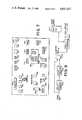
- FIG. 1is a block diagram schematic of a prior art pulsed laser.
- FIG. 2is a block diagram schematic of an improved pulsed laser
- FIG. 3is a more detailed schematic of a switching portion of the improved pulsed laser of FIG. 2.
- FIG. 4is a representation of a switching signal output of a portion of the schematic of FIG. 3.
- FIG. 5is a simplified block diagram of a portion of an ophthalmic laser system.
- FIG. 6is a simplified block diagram of a control circuit portion of an ophthalmic laser system shown coupled to a laser.
- FIG. 7is a detailed representation of the control panel portion of FIG. 6.
- FIG. 8is a more detailed block diagram of the counter circuit portion of the control circuit of FIG. 6.
- FIG. 9is a more detailed block diagram of the hardware limiter portion of the control circuit of FIG. 6.
- FIG. 10is a block diagram flow chart showing the operation of the ophthalmic laser system of the present invention for representative modes of operation.
- FIG. 1is a schematic representation of a prior art pulsed laser designated generally 100. It comprises an argon laser tube 102 having a cathode 106 and anode 104. A voltage V from voltage source 108 is applied to the cathode 106 and anode 104 through a pulse forming network (PFN) 110. An inductor 112 and diode 114 are placed in series between the voltage source 108 and one terminal of PFN 110. The laser 100 further comprises a trigger circuit 120 coupled to a wire coil 122 which surrounds tube 102. For an example of a pulsed gas laser with radiation coupling, see U.S. Pat. No. 3,626,325.
- the PFN 110is a conventional LC filter arrangement comprised of inductors and capacitors. By selecting properly the inductance, L, and the capacitance, C, the pulse width of the laser pulse can be defined. However, once the PFN 110 is designed, the pulse width becomes fixed.
- the PFN 110stores a fixed amount of energy from voltage source 108.
- the trigger circuit 120applies a voltage pulse across coil 122
- the argon gas within tube 102is ionized.
- the ionized gasprovides a pathway through which the energy in the PFN 110 can discharge from the cathode 106 to anode 104 causing the laser to lase until the energy in the circuit is depleted.
- the PFN 110begins to store energy once again but it will not discharge until the trigger circuit pulses the coil again.
- the pulse width of the laser output pulseis fixed and determined by the LC constant of the PFN 110 while the triggering circuit 120 determines the pulse repetition rate of the pulses.
- the pulse repetition ratecan be varied by the triggering pulses, there being a limit on the maximum rate determined by the design of the PFN 110.
- FIG. 2is a schematic representation of a pulsed laser designated generally 200 and suitable for use as the laser 200 in FIGS. 5 and 6. It comprises the tube 102 of FIG. 1 with cathode 106, anode 104 and voltage source 108. It further comprises a new power transistor switching circuit 210 and the trigger circuit 120 with coil 122 of FIG. 1.
- the power switching circuit 210replaces the PFN 110 and inductor-diode combination 112 and 114 of FIG. 1. With the power switching circuit 210, it is possible to generate variable pulse width laser output pulses. Since the pulse repetition rate is also determined by the switching circuit 210, the trigger circuit 120 is pulsed one time to ionize the gas and thereafter remains on continuously at a lower power level in a glow mode.
- the power switching circuit 210There are several critical requirements that the power switching circuit 210 must meet.
- the firstis the ability to provide a variable pulse width laser output.
- the range of pulse width variationis defined by the intended modes of operation of the laser. For example, it has been found that when using a pulsed laser in a perforation procedure, such as an iridotomy, a series of pulses each with a pulse width of 120 microseconds performs well. When performing a coagulation procedure, a relatively rapid pulse repetition rate with smaller pulse widths, such as 30 microsecond pulse widths, are desirable. The 30 microsecond pulse width is not as likely to cause perforation. Therefore, it is desirable to provide variable pulse widths from at least 30 microseconds to 120 microseconds.
- the power switching circuit 210must be capable of providing a large current (e.g. 100 amps) to the laser tube 102 during lasing.
- the currentis a function of the impedance of the tube 102 and voltage across the tube, V.
- the impedance of the tubeis four ohms resistive and the voltage is 500 volts.
- it is desirable to use a pulsed transformer to drive the power transistorbecause a transformer provides a sharp pulse termination with a negative going voltage at the pulse trailing edge.
- FIG. 3is a detailed schematic of the power switching circuit 210 of FIG. 2.
- the circuitcomprises of ferroresonant transformer circuit designated generally 300 comprising a first pair of primary coils 302 and 304 coupled to input terminals 301 and 303 via a switch 306; a second set of primary coils 308 and 310 wound oppositely from the first primary pair and coupled to the input terminals; a pair of secondary coils 312 and 314; and iron cores 316 and 318.
- the secondary coils 312 and 314are in series and are coupled to three parallel power transistor output circuits designated generally 322, 324, and 326.
- transformer circuit 300It is the function of the transformer circuit 300 to provide switching signals to the transistor circuits with a variable pulse width in response to pulsed control signals applied to switch 306. To drive the transistor circuits a 6 V 15-20 amp switching signal is required. As mentioned earlier the pulse width must be variable over at least a 30 microsecond to 120 microsecond range.
- the maximum pulse width of the output from any transformeris a function of the voltage and time.
- a transformer that is pulsedwill saturate at some fundamental limit of the transformer.
- a pulse transformer suitable for a pulsed argon laser systemwill saturate at a 30 microsecond pulse width.
- To double the pulse widtha pair of primary windings 302 and 304 and associated secondary windings 312 and 314, respectively, are used. This halves the voltage across each winding and doubles the overall pulse width to 60 microseconds before saturation occurs. It is possible to double the pulse width again to 120 microseconds by recognizing that the ferroresonant transformer follows a magnetic hysteresis curve.
- a 50 volt potentialis constantly applied to the input terminals 301 and 303. While switch 306 is open the 50 volts is applied through 50 ohm resistor 320 to the second pair of primary windings 308 and 310. This biases the cores 316 and 318 into saturation in one direction. Remember the windings 308 and 310 are wound oppositely from the primary windings 302 and 304.
- switch 306is closed for the duration of the desired pulse width and the 50 volts is applied to the windings 302 and 304.
- Circuit 322comprises a Motorola MJ10016 power transistor 330.
- the base of the transistoris coupled through a pair of diodes 332 and 334 and a 0.10 ohm resistor 336 to an output terminal 337 of the secondary winding pair 312 and 314.
- the emitter of the transistor 330is coupled through a 0.02 ohm resistor 338 to the remaining output terminal 339 of the secondary winding pair.
- the collectoris coupled to the cathode of the laser tube and also through diode 340 to the resistor 336.
- the baseis coupled along an alternate path through diode 342 to the resistor 336.
- the collector diode 340 and one of the base diodes of pair 332 and 334simulate a transistor coupled to transistor 330 to form a Darlington transistor circuit.
- the second transistorin this case the power transistor 330
- the first transistorin this case the diode pair 340 and either 332 or 334. This results in quicker switching action when the transistor circuit is turned off.
- the base diode 342decreases the switching time at turn off by removing stored base charge when the input pulse goes negative.
- the tube 102typically draws 100 amps, varying between 90 and 150 amps.
- Transistor 330is driven with a forced current gain of approximately 10.
- the ferroresonant transformerprovides a 6 V 15-20 amp base drive signal.
- the collectors of each of the transistors of circuits 322, 324, and 326are combined at point 350 which is coupled to the cathode 106. The transistors are therefore able to meet the tube's current requirements.
- one advantage of the pulsed transformer driveis that as the input voltage is shut off the output voltage of the transformer goes sharply negative helping to shut off the transistors. However, too deep a reverse voltage could damage the transistor and must be controlled. This is accomplished using the 75 ohm resistors 360 and 362 which are in parallel with the primary windings 302 and 304, respectively. The values of these resistors control the depth of the negative going portion 402 of the switching signal 400 shown in FIG. 4. As mentioned earlier the turn off response of the transistors is also aided by the diode 342 for removal of stored base charge.
- the lead 370 running from the transistor switch circuit on the circuit board to the cathode of the tubehas a finite length with an inductance associated therewith.
- a voltage transientis created by the lead inductance. This transient is capable of damaging the power transistors in the circuits 322, 324 and 326.
- a clamping circuit 380comprising diode 382 and capaciter 384 is provided across the output of circuits 322, 324 and 326.
- the energy from the transientis stored in capacitor 384 which then bleeds off the energy slowly during the inter pulse intervals to the main power supply capacitors.
- FIG. 5is a simplified block diagram of an ophthalmic laser system designated generally 500.
- Laser light from a laser such as the laser 200enters the focusing lense assembly 502 onto aiming mirror 504 and then to the target 506.
- Target 506 in FIG. 5depicts a conventional light intensity meter which measures the intensity of the laser light incident thereon. This is used during the laser calibration procedure but normally, for ophthalmic lasers, the target is a human eye.
- Aiming mirror 504is pivotable and is controlled by the doctor by handle 510.
- spot sizeis controlled manually by the doctor by turning knurled knob 520. Turning of this knob controls the spacing between lenses 522 and 524 within the lense housing 530. When the knob 520 is turned one way or the other the lenses are caused to move toward or away from another in the directions of the double arrow. Such an arrangement of lenses is well known in the prior art. In the present invention spot size is variable from 50 to 1500 microns.
- Photocell 516generates a voltage in response thereto which is related to the power of the laser beam and which is used by the computer to determine the power or energy actually delivered to the target during a burst or treatment.
- the system 500further comprises a biomicroscope 540 and objective lens 542 through which the doctor is enabled to see the eye.
- a biomicroscope 540 and objective lens 542through which the doctor is enabled to see the eye.
- the doctorcontrols firing of the laser by a foot switch. Before firing the doctor aims the laser beam which is at low power and adjusts the spot size appropriately for the procedure.
- the laser system 500 while onis in the aiming mode unless the doctor fires the laser.
- the doctoris able to see into the eye at the same time that the laser beam is reflected off the mirror 504 into the eye.
- a conventional shutter arrangementis employed to block the line of sight from the doctor's eye to the laser beam during firing of the laser.
- FIG. 6an overall block diagram of a control circuit portion 600 of an ophthalmic laser system is shown coupled to a laser such as laser 200.
- the control circuitcomprises a control panel 602, a foot switch 603, a microprocessor controller 604, counter circuit 606 and hardware limiter 608.
- the microprocessor controller 604 in the preferred embodimentis an Intel 8088 microprocessor chip.
- FIG. 7shows the details of the control panel 602 including the various modes of operation of the laser system. It represents the operator command interface to the laser system. In general the operator commands are entered by depressing an appropriate button on the panel.
- the control panelis really a custom made keyboard and the commands are digitized and transmitted via bus 610 to the microprocessor controller 604 where they are interpreted and ultimately converted to signals which set or load counters in the counter circuit 606.
- the counter control signalsset the pulse repetition rate, pulse width and exposure time of the control signals sent to the switch 306.
- the microprocessor controller 604automatically sets the pulse width of the control signals up to 120 microseconds depending on the mode of operation.
- the power switch 702turns on a slit lamp.
- the brightness of the slit lamp(not shown, but a conventional device used with the biomicropscope 540 to illuminate the eye so the operator can see) and the panel illumination are controlled by knobs 704 and 706, respectively.
- the operatorcan select either the coagulation or perforation modes via buttons 708 and 710, respectively. These modes will be discussed in more detail hereinafter.
- the laser systemis capable of operating an argon or krypton laser generating three colors: blue/green; green; or red. The color desired is selected by a button in the area 712 of the panel.
- the exposure time for any particular treatmentcan be selected at location 714 and displayed in display areas 716 and 718.
- the powercan be varied at location 720 while in the perforation mode, the pulse repetition rate can be varied at location 722 and displayed at location 724.
- the intensity of the aim beamcan be varied at location 726.
- Lense assembly 502further comprises a potentiometer coupled to the knob 520.
- the potentiometerchanges providing a voltage which is a function of the spot size of the laser beam.
- the relationship between spot size and voltageis measured and plotted for each model slit lamp and zoom lense combination such as a Zeiss Model 100/16 slit lamp with Britt Corporation zoom lense made for that slit lamp and commercially available.
- the plotted curveis then described in the software of the microprocessor 604 so that the spot size can be determined from the potentiometer voltage.
- the spot sizeis displayed at location 730.
- the laser systemis capable of being calibrated, a process to be described hereinafter. Calibration is triggered by pressing the button 732. Finally, where a lengthly treatment procedure is required, such as in a pan retinal photocoagulation procedure, a special REPEAT mode is provided which allows treatment bursts at pre-set intervals to reduce operator fatigue.
- the REPEAT modeis set up at location 740 and will be discussed in more detail hereinafter.
- Buttons 744, 746, 748 and 750cause display area 742 to display various parameters such as cumulative energy (to be described later); aim power; peak power; and tube pressure.
- Display areas 752 and 754display the average power delivered and the average power entered for a given burst of laser pulses delivered for a coagulation treatment.
- the control signalsare generated by the counter circuit of FIG. 8.
- the microprocessor controller 604In response to the operator commands and mode selection via panel 602, the microprocessor controller 604 automatically determines the proper pulse width and sets counter 802 appropriately. Microprocessor controller 604 also sets counter 804 to produce the proper pulse repetition rate and loads counter 806 with an exposure time count. The exposure time count is displayed at display lcoation 718.
- the counters 802 and 804operate in response to a one MHz clock provided via lead 808.
- Counter 804provides periodic output signals at the pulse repetition rate set by the microprocessor.
- Counter 802in response to each output signal from counter 804 generates a pulse with the proper pulse width which is transmitted via lead 612 to the hardware limiter circuitry 608.
- the output signals from counter 804are also sent to counter 806 which counts them down from the count loaded therein by the microprocessor. When zero is reached counter 806 automatically stops counter 804.
- Circuit 608includes a first one shot multivibrator circuit 902 which is triggered by the output pulses of counter 802.
- One shot 902provides a 3 millisecond long output signal to one shot circuit 904.
- one shot 904provides a 120 microsecond long pulse which is combined together with the original input pulse from counter circuit 802 in AND gate 906 to provide the switching signal to switch 306 which in the preferred embodiment is a transistor switch.
- the circuit of FIG. 9controls the output of the computer/counter circuit combination to prevent it from producing pulse rates or widths which will damage the laser.
- the output from AND gate 906is also transmitted to one shot multi-vibrator 908 which provides a signal to trigger circuit 120 in FIG. 2 to ionize the laser tube 102.
- one shot multi-vibrator 908which provides a signal to trigger circuit 120 in FIG. 2 to ionize the laser tube 102.
- a resister in the tube power circuitsenses the current and a signal is provided to opto isolator circuit 910 which inhibits the one shot 908.
- Circuit 910provides isolation between the tube's power supply and the control circuit.
- the microprocessor controlled counter circuit design approachis utilized to provide a fail safe feature.
- the microprocessorsets and loads the counters in accordance with the inputs received from the operator through the control panel.
- One inputis the exposure time which is provided as a loaded exposure time count in counter 806.
- the beamis continuously on at low power, that is, at a low repetition rate and short pulse width as set by the operator (location 726) and microprocessor 604. No foot pedal is depressed.
- the counters 802 and 804are set appropriately and counter 806 is loaded with a predetermined count number.
- the microprocessoris programmed to repeatedly reload counter 806 with the predetermined count before the count reaches zero during the aiming mode. If for some reason the microprocessor fails, the aiming beam will go off automatically when the last loaded count reaches zero.
- the operatorselects either the coagulation mode 1002 or perforation mode 1004.
- the perforation modeas explained earlier, it is desirable to provide high power pulses.
- the operatorselects the repetition rate desired 1006 and the exposure time 1008.
- the microprocessorautomatically selects a 120 microsecond pulse width for high power.
- the operatoradjusts the spot size 1010 and when ready depresses the foot pedal 1011.
- the microprocessorsets counter 802 and 804 and loads counter 806 and then enables the counters.
- the control pulsesare provided to laser 200 which in turn fires the programmed burst of laser pulses to the target.
- the coagulation modeoperates with smaller pulse widths than the perforation mode.
- the operatorselects desired power level 1012 and exposure time 1013. If the selected power setting is at maximum level 1014 the microprocessor selects a pulse width of 30 microseconds and an appropriate pulse repetition rate less than or equal to 3000 Hz to attain the power level 1016. For lower power levels the microprocessor first lowers the repetiton rate. However, the repetiton rate will not be lowered below 50 Hz 1018. If the desired power setting is still not attained 1020 then the microprocessor reduces pulse width 1022. The operator selects the desired spot size 1010 and depresses the foot pedal 1011 and the microprocessor takes over as before.
- the laser system of the present inventionis equipped with a calibration mode 1030.
- a light intensity meter 506is positioned in the target location 1032.
- the operatorpushes button 732, then depresses the foot pedal and adjusts the power setting (at location 720) until the light intensity meter indicates that the delivered laser power is at a predetermined power setting for example, 1 Watt 1034.
- the microprocessorthen has the pulse width and repetition rate setting which provides the calibrated power level 1036. For example,
- P T in wattsis the above ratio of (pulse width)(pulse repetition rate) products.
- the laser systemuses this equation to set up the pulse width and repetition rate of a burst of laser pulses to meet the power input selected by the operation in the coagulation mode at location 720. Also, using this equation, the laser system, for either the coagulation mode or performation mode, calculates the average power entered for each burst and display it at location 754.
- the output of the photocell 516is calibrated at the same time as PW C and PRR C 1038.
- the calibrated photocell output voltage V Cis related to P C . Part of the proportionality is due to the percentage of power split off by beam splitter 514.
- the average power actually delivered during any given treatment (either coagulation or perforation) as determined by the photocell voltagecan be determined from the voltage output of the photocell during the treatment, V T , V C and P C .
- the average power delivered during a treatment burst as determined from V T , V C and P Cis displayed at location 752.
- the energy deliveredis related to power by multiplying the average power delivered by the amount of time over which the power is delivered.
- the energy delivered for any given burstis determined by multiplying the power delivered as determined by the photocell voltage and the exposure time set by the operation at location 714, displayed at 716. Cumulative energy for a total treatment involving a plurality of bursts is determined by adding up the energy delivered for each burst.
- the energy density for each burstis determined by dividing the energy delivered as determined above by the spot size as determined by the potentiometer voltage 1042. If the diameter of the spot is reduced by a factor of two the area is reduced by a factor of 4 and the energy density increases by a factor of 4. Realizing the effects of reducing spot size when performing perforations or coagulation procedures is very important for proper treatment and avoidance of unnecessary eye damage.
- the present inventionovercomes this problem by providing a REPEAT mode of operation.
- the operatordepresses the repeat mode button 770 in location 740.
- the operatorselects a time interval which is displayed in area 774.
- the operatordepresses the enter button 776.
- the repeat modeis set up. See steps 1050 and 1052 in FIG. 10.
- the operatordepresses the foot pedal 603 moving it from the off position to the on position 1011.
- the burst of laser pulses set up in the performation mode 1004 or coagulation mode 1002 before the button 770 was depressedwill automatically be repeated at the interval selected by buttons 772 and 776.
- the burstswill continue as long as the foot pedal 603 is depressed by the operator.
- poer control meansbesides a foot pedal could be used, e.g., a manually depressed button.
- buttons 760can be pressed and a history of the treatment is printed out on a printer not shown.
Landscapes
- Health & Medical Sciences (AREA)
- Physics & Mathematics (AREA)
- Ophthalmology & Optometry (AREA)
- Engineering & Computer Science (AREA)
- Electromagnetism (AREA)
- Optics & Photonics (AREA)
- Surgery (AREA)
- Nuclear Medicine, Radiotherapy & Molecular Imaging (AREA)
- Plasma & Fusion (AREA)
- Biomedical Technology (AREA)
- Heart & Thoracic Surgery (AREA)
- Vascular Medicine (AREA)
- Life Sciences & Earth Sciences (AREA)
- Animal Behavior & Ethology (AREA)
- General Health & Medical Sciences (AREA)
- Public Health (AREA)
- Veterinary Medicine (AREA)
- Laser Surgery Devices (AREA)
Abstract
Description
The present invention relates to a pulsed laser system, more particulary, to a control circuit for providing variable pulse width control signals to the laser to control its output.
Prior art pulsed lasers use an LC pulse forming network connected to the anode of the tube to store the energy for the laser pulse. A trigger circuit applies a triggering pulse to a coil wrapped around the laser tube which ionizes the argon gas within the tube. This provides a discharge path for the energy stored in the pulse forming network through the laser tube to the cathode causing the tube to lase. However, the laser pulse width is fixed by the LC constant of the PFN. The pulse repetition rate is controlled by the triggering pulses, but the pulse width remains fixed.
When performing perforation procedures such as iridotomies, it is desirable to provide a finite number of high power pulses with predetermined pulse widths. When performing thermal procedures such as coagulation, it is desirable to provide near CW tube operation at relatively low power levels which requires a combination of pulse width and repetition rate to control the energy being delivered. A pulse width which is fixed and optimized for perforation procedures will not in general be optimzed for coagulation procedures.
It is desirable, therefore, to provide a pulsed laser which provides laser pulses with pulse width and repetition rate which vary over a relatively wide range.
When using pulsed lasers in a therapeutic laser system such as in the treatment of the eye, it is also desireable to determine the energy and energy density delivered to the eye during treatment. Because the power of the laser output is adjusted by varying pulse width and repetition rate it is also highly desireable to simplify the requirements of the operator's inputs when using the variable pulse width pulsed laser by providing automatic determination of optimum pulse width.
Finally, it is highly desireable to reduce operator fatigue encountered in lengthy treatment procedures.
The present invention is directed to a pulse laser system comprising a power switching circuit for providing drive signals to a pulsed laser to generate a burst of laser pulses suitable for a particular treatment. The burst is generated in response to a series of control signals which in turn are generated by a control circuit which sets the pulse repetition rate, pulse width and exposure time of the control signals.
A treatment switch such as a foot pedal or other suitable means is movable between off and on positions for causing the control signals to be applied to the laser thereby generating the burst of laser pulses. Means are provided for automatically repeating the burst of laser pulses at a predetermined interval which the treatment switch remains in the on position.
FIG. 1 is a block diagram schematic of a prior art pulsed laser.
FIG. 2 is a block diagram schematic of an improved pulsed laser
FIG. 3 is a more detailed schematic of a switching portion of the improved pulsed laser of FIG. 2.
FIG. 4 is a representation of a switching signal output of a portion of the schematic of FIG. 3.
FIG. 5 is a simplified block diagram of a portion of an ophthalmic laser system.
FIG. 6 is a simplified block diagram of a control circuit portion of an ophthalmic laser system shown coupled to a laser.
FIG. 7 is a detailed representation of the control panel portion of FIG. 6.
FIG. 8 is a more detailed block diagram of the counter circuit portion of the control circuit of FIG. 6.
FIG. 9 is a more detailed block diagram of the hardware limiter portion of the control circuit of FIG. 6.
FIG. 10 is a block diagram flow chart showing the operation of the ophthalmic laser system of the present invention for representative modes of operation.
FIG. 1 is a schematic representation of a prior art pulsed laser designated generally 100. It comprises anargon laser tube 102 having acathode 106 andanode 104. A voltage V fromvoltage source 108 is applied to thecathode 106 andanode 104 through a pulse forming network (PFN) 110. An inductor 112 anddiode 114 are placed in series between thevoltage source 108 and one terminal ofPFN 110. Thelaser 100 further comprises atrigger circuit 120 coupled to awire coil 122 which surroundstube 102. For an example of a pulsed gas laser with radiation coupling, see U.S. Pat. No. 3,626,325.
The PFN 110 is a conventional LC filter arrangement comprised of inductors and capacitors. By selecting properly the inductance, L, and the capacitance, C, the pulse width of the laser pulse can be defined. However, once the PFN 110 is designed, the pulse width becomes fixed.
The PFN 110 stores a fixed amount of energy fromvoltage source 108. When thetrigger circuit 120 applies a voltage pulse acrosscoil 122, the argon gas withintube 102 is ionized. The ionized gas provides a pathway through which the energy in thePFN 110 can discharge from thecathode 106 toanode 104 causing the laser to lase until the energy in the circuit is depleted. The PFN 110 begins to store energy once again but it will not discharge until the trigger circuit pulses the coil again. The pulse width of the laser output pulse is fixed and determined by the LC constant of thePFN 110 while the triggeringcircuit 120 determines the pulse repetition rate of the pulses. The pulse repetition rate can be varied by the triggering pulses, there being a limit on the maximum rate determined by the design of thePFN 110.
FIG. 2 is a schematic representation of a pulsed laser designated generally 200 and suitable for use as thelaser 200 in FIGS. 5 and 6. It comprises thetube 102 of FIG. 1 withcathode 106,anode 104 andvoltage source 108. It further comprises a new powertransistor switching circuit 210 and thetrigger circuit 120 withcoil 122 of FIG. 1. Thepower switching circuit 210 replaces thePFN 110 and inductor-diode combination 112 and 114 of FIG. 1. With thepower switching circuit 210, it is possible to generate variable pulse width laser output pulses. Since the pulse repetition rate is also determined by theswitching circuit 210, thetrigger circuit 120 is pulsed one time to ionize the gas and thereafter remains on continuously at a lower power level in a glow mode.
There are several critical requirements that thepower switching circuit 210 must meet. The first is the ability to provide a variable pulse width laser output. The range of pulse width variation is defined by the intended modes of operation of the laser. For example, it has been found that when using a pulsed laser in a perforation procedure, such as an iridotomy, a series of pulses each with a pulse width of 120 microseconds performs well. When performing a coagulation procedure, a relatively rapid pulse repetition rate with smaller pulse widths, such as 30 microsecond pulse widths, are desirable. The 30 microsecond pulse width is not as likely to cause perforation. Therefore, it is desirable to provide variable pulse widths from at least 30 microseconds to 120 microseconds. Secondly, thepower switching circuit 210 must be capable of providing a large current (e.g. 100 amps) to thelaser tube 102 during lasing. The current is a function of the impedance of thetube 102 and voltage across the tube, V. Typically, the impedance of the tube is four ohms resistive and the voltage is 500 volts. Finally, it is desirable to use a pulsed transformer to drive the power transistor because a transformer provides a sharp pulse termination with a negative going voltage at the pulse trailing edge.
FIG. 3 is a detailed schematic of thepower switching circuit 210 of FIG. 2. The circuit comprises of ferroresonant transformer circuit designated generally 300 comprising a first pair ofprimary coils terminals switch 306; a second set ofprimary coils secondary coils iron cores secondary coils
It is the function of thetransformer circuit 300 to provide switching signals to the transistor circuits with a variable pulse width in response to pulsed control signals applied to switch 306. To drive the transistor circuits a 6 V 15-20 amp switching signal is required. As mentioned earlier the pulse width must be variable over at least a 30 microsecond to 120 microsecond range.
The maximum pulse width of the output from any transformer is a function of the voltage and time. A transformer that is pulsed will saturate at some fundamental limit of the transformer. For example, a pulse transformer suitable for a pulsed argon laser system will saturate at a 30 microsecond pulse width. To double the pulse width a pair ofprimary windings secondary windings
In the present invention, a 50 volt potential is constantly applied to theinput terminals switch 306 is open the 50 volts is applied through 50ohm resistor 320 to the second pair ofprimary windings cores windings primary windings transistor switching circuit 210 to pulse the laser,switch 306 is closed for the duration of the desired pulse width and the 50 volts is applied to thewindings cores windings switch 306 it takes twice as long to drive thecores primary windings
All of the transistor circuits are identical andonly circuit 322 will be described in detail.Circuit 322 comprises a MotorolaMJ10016 power transistor 330. The base of the transistor is coupled through a pair ofdiodes ohm resistor 336 to anoutput terminal 337 of the secondary windingpair transistor 330 is coupled through a 0.02ohm resistor 338 to the remainingoutput terminal 339 of the secondary winding pair. The collector is coupled to the cathode of the laser tube and also throughdiode 340 to theresistor 336. Finally the base is coupled along an alternate path throughdiode 342 to theresistor 336.
Thecollector diode 340 and one of the base diodes ofpair transistor 330 to form a Darlington transistor circuit. As is well known in the art, the second transistor (in this case the power transistor 330) is kept from saturating by the action of the first transistor (in this case thediode pair 340 and either 332 or 334). This results in quicker switching action when the transistor circuit is turned off.
Thebase diode 342 decreases the switching time at turn off by removing stored base charge when the input pulse goes negative.
As mentioned above, thetube 102 typically draws 100 amps, varying between 90 and 150 amps.Transistor 330 is driven with a forced current gain of approximately 10. The ferroresonant transformer provides a 6 V 15-20 amp base drive signal. The collectors of each of the transistors ofcircuits point 350 which is coupled to thecathode 106. The transistors are therefore able to meet the tube's current requirements.
It is highly desireable in a pulsed ophthalmic laser system to have maximum control over the laser drive pulses. For example, one advantage of the pulsed transformer drive is that as the input voltage is shut off the output voltage of the transformer goes sharply negative helping to shut off the transistors. However, too deep a reverse voltage could damage the transistor and must be controlled. This is accomplished using the 75ohm resistors primary windings negative going portion 402 of theswitching signal 400 shown in FIG. 4. As mentioned earlier the turn off response of the transistors is also aided by thediode 342 for removal of stored base charge.
Thelead 370 running from the transistor switch circuit on the circuit board to the cathode of the tube has a finite length with an inductance associated therewith. When the high current flowing through the lead is suddenly terminated because the transistors are turned off so sharply, a voltage transient is created by the lead inductance. This transient is capable of damaging the power transistors in thecircuits clamping circuit 380 comprisingdiode 382 andcapaciter 384 is provided across the output ofcircuits capacitor 384 which then bleeds off the energy slowly during the inter pulse intervals to the main power supply capacitors. By positioning a small compacitor (0.1 microfarad) on the transistor circuit circuit board close to the transistors, little inductance is associated with the clamping circuit itself and the transient is deflected from the transistors.
FIG. 5 is a simplified block diagram of an ophthalmic laser system designated generally 500. Laser light from a laser such as thelaser 200 enters the focusing lenseassembly 502 onto aimingmirror 504 and then to thetarget 506.Target 506 in FIG. 5 depicts a conventional light intensity meter which measures the intensity of the laser light incident thereon. This is used during the laser calibration procedure but normally, for ophthalmic lasers, the target is a human eye. Aimingmirror 504 is pivotable and is controlled by the doctor byhandle 510.
Focusing of the laser beam to control spot size as it impinges on the target surface within the eye is extremely important. Spot size is controlled manually by the doctor by turningknurled knob 520. Turning of this knob controls the spacing betweenlenses lense housing 530. When theknob 520 is turned one way or the other the lenses are caused to move toward or away from another in the directions of the double arrow. Such an arrangement of lenses is well known in the prior art. In the present invention spot size is variable from 50 to 1500 microns.
A portion of the laser beam is split off bybeam splitter 514 and directed to impinge onphotocell 516.Photocell 516 generates a voltage in response thereto which is related to the power of the laser beam and which is used by the computer to determine the power or energy actually delivered to the target during a burst or treatment.
Thesystem 500 further comprises abiomicroscope 540 andobjective lens 542 through which the doctor is enabled to see the eye. These are well known in the art. See for example, Britt Corporation's Model 152 Ophthalmic Laser. The doctor controls firing of the laser by a foot switch. Before firing the doctor aims the laser beam which is at low power and adjusts the spot size appropriately for the procedure. Thelaser system 500 while on is in the aiming mode unless the doctor fires the laser. The doctor is able to see into the eye at the same time that the laser beam is reflected off themirror 504 into the eye. A conventional shutter arrangement, not shown, is employed to block the line of sight from the doctor's eye to the laser beam during firing of the laser.
Referring now to FIG. 6, an overall block diagram of acontrol circuit portion 600 of an ophthalmic laser system is shown coupled to a laser such aslaser 200. The control circuit comprises acontrol panel 602, afoot switch 603, amicroprocessor controller 604,counter circuit 606 andhardware limiter 608. Themicroprocessor controller 604 in the preferred embodiment is an Intel 8088 microprocessor chip.
FIG. 7 shows the details of thecontrol panel 602 including the various modes of operation of the laser system. It represents the operator command interface to the laser system. In general the operator commands are entered by depressing an appropriate button on the panel. The control panel is really a custom made keyboard and the commands are digitized and transmitted viabus 610 to themicroprocessor controller 604 where they are interpreted and ultimately converted to signals which set or load counters in thecounter circuit 606. The counter control signals set the pulse repetition rate, pulse width and exposure time of the control signals sent to theswitch 306. Themicroprocessor controller 604 automatically sets the pulse width of the control signals up to 120 microseconds depending on the mode of operation.
Thepower switch 702 turns on a slit lamp. The brightness of the slit lamp (not shown, but a conventional device used with thebiomicropscope 540 to illuminate the eye so the operator can see) and the panel illumination are controlled byknobs 704 and 706, respectively. The operator can select either the coagulation or perforation modes viabuttons area 712 of the panel.
The exposure time for any particular treatment can be selected atlocation 714 and displayed indisplay areas location 720 while in the perforation mode, the pulse repetition rate can be varied atlocation 722 and displayed atlocation 724.
When the laser system is on and between treatments the system produces an aiming mode as described earlier. The intensity of the aim beam can be varied atlocation 726.
The laser system is capable of being calibrated, a process to be described hereinafter. Calibration is triggered by pressing thebutton 732. Finally, where a lengthly treatment procedure is required, such as in a pan retinal photocoagulation procedure, a special REPEAT mode is provided which allows treatment bursts at pre-set intervals to reduce operator fatigue. The REPEAT mode is set up atlocation 740 and will be discussed in more detail hereinafter.
Before discussing the modes of operation of the laser system in more detail reference is made to FIGS. 8 and 9. The control signals are generated by the counter circuit of FIG. 8. In response to the operator commands and mode selection viapanel 602, themicroprocessor controller 604 automatically determines the proper pulse width and sets counter 802 appropriately.Microprocessor controller 604 also sets counter 804 to produce the proper pulse repetition rate and loads counter 806 with an exposure time count. The exposure time count is displayed atdisplay lcoation 718.
Thecounters lead 808.Counter 804 provides periodic output signals at the pulse repetition rate set by the microprocessor.Counter 802 in response to each output signal fromcounter 804 generates a pulse with the proper pulse width which is transmitted vialead 612 to thehardware limiter circuitry 608.
The output signals fromcounter 804 are also sent to counter 806 which counts them down from the count loaded therein by the microprocessor. When zero is reached counter 806 automatically stopscounter 804.
The functions of all three counter circuits as shown in FIG. 8 are provided by proper connection of an INTEL 8253 integrated circuit.
The hardware limiter circuitry as shown in some detail in FIG. 9 limits the maximum pulse width (no greater than 120 microseconds) and maximum repetition rate (not to exceed 3000 per second).Circuit 608 includes a first oneshot multivibrator circuit 902 which is triggered by the output pulses ofcounter 802. Oneshot 902 provides a 3 millisecond long output signal to oneshot circuit 904. On the rising edge of the output from oneshot 902, one shot 904 provides a 120 microsecond long pulse which is combined together with the original input pulse fromcounter circuit 802 in AND gate 906 to provide the switching signal to switch 306 which in the preferred embodiment is a transistor switch. Since the output ofcounter 802 is combined with a 120 microsecond pulse to produce the laser pulse the laser pulse cannot exceed 120 microsecond even if through some error themicroprocessor 604 sets counter 802 with a longer pulse. Since the 120 microsecond long pulse is only produced at the rising edge of the output of oneshot 902 it cannot occur more than 3000 times per second. The circuit of FIG. 9 controls the output of the computer/counter circuit combination to prevent it from producing pulse rates or widths which will damage the laser.
The output from AND gate 906 is also transmitted to oneshot multi-vibrator 908 which provides a signal to triggercircuit 120 in FIG. 2 to ionize thelaser tube 102. However, if the tube is already in a low power glow mode a resister in the tube power circuit senses the current and a signal is provided toopto isolator circuit 910 which inhibits the oneshot 908.Circuit 910 provides isolation between the tube's power supply and the control circuit.
The microprocessor controlled counter circuit design approach is utilized to provide a fail safe feature. When thefoot pedal 603 is depressed the microprocessor sets and loads the counters in accordance with the inputs received from the operator through the control panel. One input is the exposure time which is provided as a loaded exposure time count incounter 806. When the count reaches zero the laser stops firing until thefoot pedal 603 is depressed again. In the aim mode the beam is continuously on at low power, that is, at a low repetition rate and short pulse width as set by the operator (location 726) andmicroprocessor 604. No foot pedal is depressed. In this mode (activated whenever the system is on but during pretreatment intervals) thecounters counter 806 is loaded with a predetermined count number. The microprocessor is programmed to repeatedly reload counter 806 with the predetermined count before the count reaches zero during the aiming mode. If for some reason the microprocessor fails, the aiming beam will go off automatically when the last loaded count reaches zero.
Referring now to FIG. 10, the operator selects either thecoagulation mode 1002 orperforation mode 1004. In the perforation mode as explained earlier, it is desirable to provide high power pulses. The operator selects the repetition rate desired 1006 and theexposure time 1008. The microprocessor automatically selects a 120 microsecond pulse width for high power. The operator adjusts thespot size 1010 and when ready depresses thefoot pedal 1011. The microprocessor sets counter 802 and 804 and loads counter 806 and then enables the counters. The control pulses are provided tolaser 200 which in turn fires the programmed burst of laser pulses to the target.
The coagulation mode operates with smaller pulse widths than the perforation mode. In the coagulation mode the operator selects desiredpower level 1012 andexposure time 1013. If the selected power setting is atmaximum level 1014 the microprocessor selects a pulse width of 30 microseconds and an appropriate pulse repetition rate less than or equal to 3000 Hz to attain thepower level 1016. For lower power levels the microprocessor first lowers the repetiton rate. However, the repetiton rate will not be lowered below 50Hz 1018. If the desired power setting is still not attained 1020 then the microprocessor reducespulse width 1022. The operator selects the desiredspot size 1010 and depresses thefoot pedal 1011 and the microprocessor takes over as before.
The laser system of the present invention is equipped with acalibration mode 1030. In this mode, alight intensity meter 506 is positioned in thetarget location 1032. The operator pushesbutton 732, then depresses the foot pedal and adjusts the power setting (at location 720) until the light intensity meter indicates that the delivered laser power is at a predetermined power setting for example, 1Watt 1034. The microprocessor then has the pulse width and repetition rate setting which provides the calibratedpower level 1036. For example,
P.sub.C α (PW).sub.C (PRR).sub.C
For a particular burst of laser output pulses to be used for treatment the power is
P.sub.T /P.sub.C α (PW).sub.T (PRR).sub.T /(PW).sub.C (PRR).sub.C.
Where PC =1 Watt, PT in watts is the above ratio of (pulse width)(pulse repetition rate) products. The equation can be rewritten as PT =(K)(PW)T (PRR)T where K is a constant incorporating 1/(PW)C (PRR)C. The laser system uses this equation to set up the pulse width and repetition rate of a burst of laser pulses to meet the power input selected by the operation in the coagulation mode atlocation 720. Also, using this equation, the laser system, for either the coagulation mode or performation mode, calculates the average power entered for each burst and display it atlocation 754.
The output of thephotocell 516 is calibrated at the same time as PWC andPRR C 1038. The calibrated photocell output voltage VC is related to PC. Part of the proportionality is due to the percentage of power split off bybeam splitter 514. The average power actually delivered during any given treatment (either coagulation or perforation) as determined by the photocell voltage can be determined from the voltage output of the photocell during the treatment, VT, VC and PC. The average power delivered during a treatment burst as determined from VT, VC and PC is displayed atlocation 752.
The energy delivered is related to power by multiplying the average power delivered by the amount of time over which the power is delivered. The energy delivered for any given burst is determined by multiplying the power delivered as determined by the photocell voltage and the exposure time set by the operation atlocation 714, displayed at 716. Cumulative energy for a total treatment involving a plurality of bursts is determined by adding up the energy delivered for each burst.
The energy density for each burst is determined by dividing the energy delivered as determined above by the spot size as determined by thepotentiometer voltage 1042. If the diameter of the spot is reduced by a factor of two the area is reduced by a factor of 4 and the energy density increases by a factor of 4. Realizing the effects of reducing spot size when performing perforations or coagulation procedures is very important for proper treatment and avoidance of unnecessary eye damage.
As mentioned earlier, in some treatment procedures such as in a pan retinal procedure, many bursts of laser power are required to complete the procedure. Where, as in the prior art, it is necessary for the operation to lift a foot from the foot pedal and then reapply the foot to depress the foot pedal for each firing the laser it can become very tiring for the operator. This, of course, is highly undesireable.
Referring to FIGS. 7 and 10, the present invention overcomes this problem by providing a REPEAT mode of operation. After the operator has selected either theperforation mode 1004 orcoagulation mode 1002 and made the necessary selections (e.g. steps repeat mode button 770 inlocation 740. Then using theset button 772, the operator selects a time interval which is displayed inarea 774. When the desired interval is displayed, the operator depresses the enter button 776. Now the repeat mode is set up. Seesteps
Following the set up of the REPEAT mode, the operator depresses thefoot pedal 603 moving it from the off position to the onposition 1011. As long as thefoot pedal 603 remains depressed, the burst of laser pulses set up in theperformation mode 1004 orcoagulation mode 1002 before thebutton 770 was depressed will automatically be repeated at the interval selected bybuttons 772 and 776. The bursts will continue as long as thefoot pedal 603 is depressed by the operator. Of course other poer control means besides a foot pedal could be used, e.g., a manually depressed button.
When the treatment is finished thebutton 760 can be pressed and a history of the treatment is printed out on a printer not shown.
Claims (3)
1. A pulsed laser system comprising:
a laser tube having electrodes;
a power switching means coupled to the electrodes of said laser tube for energizing said laser tube in response to a series of periodic control signals to generate a burst of laser output signals;
power control means movable between an off position and on position for activating said laser tube by enabling said generating means to apply said control signals to said power switching means in said on position; and repeat means coupled to said generating means for automatically repeating at a predetermined interval said burst of laser pulses generated within a preselected exposure time while said power control means is held in said on position.
2. The pulses laser system of claim 1 wherein said power control means comprises a foot pedal.
3. The pulsed laser system of claim 1 wherein said laser system is radiation cooled.
Priority Applications (6)
| Application Number | Priority Date | Filing Date | Title |
|---|---|---|---|
| US06/620,345US4601037A (en) | 1984-06-13 | 1984-06-13 | Pulsed laser system |
| HU852318AHUT38784A (en) | 1984-06-13 | 1985-06-12 | Pulse laser system |
| EP85107280AEP0164751A3 (en) | 1984-06-13 | 1985-06-12 | A pulsed laser system and method of operation |
| CA000483937ACA1273048A (en) | 1984-06-13 | 1985-06-13 | Pulsed laser system |
| JP60129739AJPS6123376A (en) | 1984-06-13 | 1985-06-13 | Pulse laser system |
| PL25395285APL253952A1 (en) | 1984-06-13 | 1985-06-13 | Method of controlling pulsed laser arrangement and pulsed laser arrangement as such |
Applications Claiming Priority (1)
| Application Number | Priority Date | Filing Date | Title |
|---|---|---|---|
| US06/620,345US4601037A (en) | 1984-06-13 | 1984-06-13 | Pulsed laser system |
Publications (1)
| Publication Number | Publication Date |
|---|---|
| US4601037Atrue US4601037A (en) | 1986-07-15 |
Family
ID=24485562
Family Applications (1)
| Application Number | Title | Priority Date | Filing Date |
|---|---|---|---|
| US06/620,345Expired - Fee RelatedUS4601037A (en) | 1984-06-13 | 1984-06-13 | Pulsed laser system |
Country Status (1)
| Country | Link |
|---|---|
| US (1) | US4601037A (en) |
Cited By (49)
| Publication number | Priority date | Publication date | Assignee | Title |
|---|---|---|---|---|
| US4995044A (en)* | 1990-03-23 | 1991-02-19 | Tektronix, Inc. | Laser diode impulse circuit |
| US5050597A (en)* | 1987-03-05 | 1991-09-24 | S.L.T. Japan Co., Ltd. | Laser irradiation system for thermotherapy |
| US5084060A (en)* | 1989-02-15 | 1992-01-28 | Freund Precision, Inc. | Apparatus for enlarging a vessel or clearing obstructive tissue from a vessel according to vessel compliance |
| US5104392A (en)* | 1985-03-22 | 1992-04-14 | Massachusetts Institute Of Technology | Laser spectro-optic imaging for diagnosis and treatment of diseased tissue |
| US5144631A (en)* | 1990-01-22 | 1992-09-01 | Fuji Photo Film Co., Ltd. | Semiconductor laser drive device |
| US5172264A (en)* | 1991-02-21 | 1992-12-15 | Surgilase, Inc. | Method and apparatus for combining continuous wave laser with TEA pulsed laser |
| US5259380A (en)* | 1987-11-04 | 1993-11-09 | Amcor Electronics, Ltd. | Light therapy system |
| US5293397A (en)* | 1992-11-24 | 1994-03-08 | Associated Universities, Inc. | Means and method for characterizing high power, ultra short laser pulses in a real time, on line manner |
| US5312396A (en)* | 1990-09-06 | 1994-05-17 | Massachusetts Institute Of Technology | Pulsed laser system for the surgical removal of tissue |
| US5383855A (en)* | 1992-08-20 | 1995-01-24 | Medex, Inc. | Electronically monitored angioplasty system |
| US5387106A (en)* | 1991-04-04 | 1995-02-07 | Powerlasers Ltd. | Solid state artificial cornea and method for UV laser sculpting |
| US5408484A (en)* | 1990-05-30 | 1995-04-18 | Weimel; Erich | Switchable energy supply for a laser system |
| US5871479A (en)* | 1996-11-07 | 1999-02-16 | Cynosure, Inc. | Alexandrite laser system for hair removal and method therefor |
| US6135995A (en)* | 1995-09-26 | 2000-10-24 | Coherent, Inc. | Electronically pulsed laser system |
| WO2001078633A3 (en)* | 2000-04-14 | 2002-07-04 | Coherent Inc | Zoom handpiece for laser surgery |
| US20030004500A1 (en)* | 1999-04-07 | 2003-01-02 | Visx, Inc. | Interface for laser eye surgery |
| US20030144713A1 (en)* | 1996-04-09 | 2003-07-31 | Cynosure, Inc. | Ultra-long flashlamp-excited pulse dye laser for therapy and method therefor |
| US6743221B1 (en)* | 2001-03-13 | 2004-06-01 | James L. Hobart | Laser system and method for treatment of biological tissues |
| US6770069B1 (en) | 2001-06-22 | 2004-08-03 | Sciton, Inc. | Laser applicator |
| US6831936B1 (en) | 1998-06-12 | 2004-12-14 | Gsi Lumonics Corporation | Pulse control in laser systems |
| US7036516B1 (en) | 1996-10-30 | 2006-05-02 | Xantech Pharmaceuticals, Inc. | Treatment of pigmented tissues using optical energy |
| US20060095097A1 (en)* | 1996-10-30 | 2006-05-04 | Provectus Devicetech, Inc. | Treatment of pigmented tissue using optical energy |
| US20090120914A1 (en)* | 2006-05-01 | 2009-05-14 | Wayne Lawrence | System and method for controlling the power level of a laser apparatus in a laser shock peening process |
| US7655002B2 (en) | 1996-03-21 | 2010-02-02 | Second Sight Laser Technologies, Inc. | Lenticular refractive surgery of presbyopia, other refractive errors, and cataract retardation |
| US8262646B2 (en) | 2006-01-20 | 2012-09-11 | Lensar, Inc. | System and method for providing the shaped structural weakening of the human lens with a laser |
| US8382745B2 (en) | 2009-07-24 | 2013-02-26 | Lensar, Inc. | Laser system and method for astigmatic corrections in association with cataract treatment |
| US8465478B2 (en) | 2009-07-24 | 2013-06-18 | Lensar, Inc. | System and method for performing LADAR assisted procedures on the lens of an eye |
| US8480659B2 (en) | 2008-07-25 | 2013-07-09 | Lensar, Inc. | Method and system for removal and replacement of lens material from the lens of an eye |
| US8500723B2 (en) | 2008-07-25 | 2013-08-06 | Lensar, Inc. | Liquid filled index matching device for ophthalmic laser procedures |
| US8556425B2 (en) | 2010-02-01 | 2013-10-15 | Lensar, Inc. | Purkinjie image-based alignment of suction ring in ophthalmic applications |
| USD694890S1 (en) | 2010-10-15 | 2013-12-03 | Lensar, Inc. | Laser system for treatment of the eye |
| USD695408S1 (en) | 2010-10-15 | 2013-12-10 | Lensar, Inc. | Laser system for treatment of the eye |
| US8617146B2 (en) | 2009-07-24 | 2013-12-31 | Lensar, Inc. | Laser system and method for correction of induced astigmatism |
| US20140052113A1 (en)* | 2012-08-17 | 2014-02-20 | Carl Zeiss Meditec Ag | Instrument system and procedure for phacoemulsification |
| US8758332B2 (en) | 2009-07-24 | 2014-06-24 | Lensar, Inc. | Laser system and method for performing and sealing corneal incisions in the eye |
| US8801186B2 (en) | 2010-10-15 | 2014-08-12 | Lensar, Inc. | System and method of scan controlled illumination of structures within an eye |
| US8915948B2 (en) | 2002-06-19 | 2014-12-23 | Palomar Medical Technologies, Llc | Method and apparatus for photothermal treatment of tissue at depth |
| US9028536B2 (en) | 2006-08-02 | 2015-05-12 | Cynosure, Inc. | Picosecond laser apparatus and methods for its operation and use |
| US9180051B2 (en) | 2006-01-20 | 2015-11-10 | Lensar Inc. | System and apparatus for treating the lens of an eye |
| US9375349B2 (en) | 2006-01-20 | 2016-06-28 | Lensar, Llc | System and method for providing laser shot patterns to the lens of an eye |
| US9393154B2 (en) | 2011-10-28 | 2016-07-19 | Raymond I Myers | Laser methods for creating an antioxidant sink in the crystalline lens for the maintenance of eye health and physiology and slowing presbyopia development |
| US9545338B2 (en) | 2006-01-20 | 2017-01-17 | Lensar, Llc. | System and method for improving the accommodative amplitude and increasing the refractive power of the human lens with a laser |
| US9780518B2 (en) | 2012-04-18 | 2017-10-03 | Cynosure, Inc. | Picosecond laser apparatus and methods for treating target tissues with same |
| US9889043B2 (en) | 2006-01-20 | 2018-02-13 | Lensar, Inc. | System and apparatus for delivering a laser beam to the lens of an eye |
| US10245107B2 (en) | 2013-03-15 | 2019-04-02 | Cynosure, Inc. | Picosecond optical radiation systems and methods of use |
| US10434324B2 (en) | 2005-04-22 | 2019-10-08 | Cynosure, Llc | Methods and systems for laser treatment using non-uniform output beam |
| US10463541B2 (en) | 2011-03-25 | 2019-11-05 | Lensar, Inc. | System and method for correcting astigmatism using multiple paired arcuate laser generated corneal incisions |
| US11389241B2 (en) | 2019-01-15 | 2022-07-19 | Boston Scientific Scimed, Inc. | Alignment method and tools |
| US11418000B2 (en) | 2018-02-26 | 2022-08-16 | Cynosure, Llc | Q-switched cavity dumped sub-nanosecond laser |
Citations (12)
| Publication number | Priority date | Publication date | Assignee | Title |
|---|---|---|---|---|
| US3481340A (en)* | 1965-06-17 | 1969-12-02 | William B Mcknight | Rapid firing laser surgical device |
| US3727061A (en)* | 1970-07-06 | 1973-04-10 | Us Army | Pulse laser communication system |
| US3747019A (en)* | 1970-07-16 | 1973-07-17 | Union Carbide Corp | Method and means for stabilizing the amplitude and repetition frequency of a repetitively q-switched laser |
| US3928815A (en)* | 1961-08-01 | 1975-12-23 | Hughes Aircraft Co | Method and apparatus for operating laser |
| US3971382A (en)* | 1973-12-11 | 1976-07-27 | Krasnov Mikhail M | Method of non-surgical treatment of cataracts |
| US4009385A (en)* | 1976-03-22 | 1977-02-22 | Bell Telephone Laboratories, Incorporated | Laser control circuit |
| US4053845A (en)* | 1967-03-06 | 1977-10-11 | Gordon Gould | Optically pumped laser amplifiers |
| US4161436A (en)* | 1967-03-06 | 1979-07-17 | Gordon Gould | Method of energizing a material |
| US4243951A (en)* | 1978-06-12 | 1981-01-06 | Rca Corporation | High repetition rate driver circuit for modulation of injection lasers |
| US4359773A (en)* | 1980-07-07 | 1982-11-16 | Bell Telephone Laboratories, Incorporated | Semiconductor lasers with selective driving circuit |
| US4409979A (en)* | 1979-11-28 | 1983-10-18 | Lasag Ag | Device for observing and treating the eye using a laser |
| US4412331A (en)* | 1981-04-22 | 1983-10-25 | M/A-Com Dcc, Inc. | Feedback circuit for controlling the peak optical output power of an injection laser |
- 1984
- 1984-06-13USUS06/620,345patent/US4601037A/ennot_activeExpired - Fee Related
Patent Citations (14)
| Publication number | Priority date | Publication date | Assignee | Title |
|---|---|---|---|---|
| US3928815A (en)* | 1961-08-01 | 1975-12-23 | Hughes Aircraft Co | Method and apparatus for operating laser |
| US3481340A (en)* | 1965-06-17 | 1969-12-02 | William B Mcknight | Rapid firing laser surgical device |
| US4053845A (en)* | 1967-03-06 | 1977-10-11 | Gordon Gould | Optically pumped laser amplifiers |
| US4161436A (en)* | 1967-03-06 | 1979-07-17 | Gordon Gould | Method of energizing a material |
| US4053845B1 (en)* | 1967-03-06 | 1987-04-28 | ||
| US4161436B1 (en)* | 1967-03-06 | 1988-04-26 | ||
| US3727061A (en)* | 1970-07-06 | 1973-04-10 | Us Army | Pulse laser communication system |
| US3747019A (en)* | 1970-07-16 | 1973-07-17 | Union Carbide Corp | Method and means for stabilizing the amplitude and repetition frequency of a repetitively q-switched laser |
| US3971382A (en)* | 1973-12-11 | 1976-07-27 | Krasnov Mikhail M | Method of non-surgical treatment of cataracts |
| US4009385A (en)* | 1976-03-22 | 1977-02-22 | Bell Telephone Laboratories, Incorporated | Laser control circuit |
| US4243951A (en)* | 1978-06-12 | 1981-01-06 | Rca Corporation | High repetition rate driver circuit for modulation of injection lasers |
| US4409979A (en)* | 1979-11-28 | 1983-10-18 | Lasag Ag | Device for observing and treating the eye using a laser |
| US4359773A (en)* | 1980-07-07 | 1982-11-16 | Bell Telephone Laboratories, Incorporated | Semiconductor lasers with selective driving circuit |
| US4412331A (en)* | 1981-04-22 | 1983-10-25 | M/A-Com Dcc, Inc. | Feedback circuit for controlling the peak optical output power of an injection laser |
Cited By (80)
| Publication number | Priority date | Publication date | Assignee | Title |
|---|---|---|---|---|
| US5104392A (en)* | 1985-03-22 | 1992-04-14 | Massachusetts Institute Of Technology | Laser spectro-optic imaging for diagnosis and treatment of diseased tissue |
| US5050597A (en)* | 1987-03-05 | 1991-09-24 | S.L.T. Japan Co., Ltd. | Laser irradiation system for thermotherapy |
| US5259380A (en)* | 1987-11-04 | 1993-11-09 | Amcor Electronics, Ltd. | Light therapy system |
| US5084060A (en)* | 1989-02-15 | 1992-01-28 | Freund Precision, Inc. | Apparatus for enlarging a vessel or clearing obstructive tissue from a vessel according to vessel compliance |
| US5144631A (en)* | 1990-01-22 | 1992-09-01 | Fuji Photo Film Co., Ltd. | Semiconductor laser drive device |
| US4995044A (en)* | 1990-03-23 | 1991-02-19 | Tektronix, Inc. | Laser diode impulse circuit |
| US5408484A (en)* | 1990-05-30 | 1995-04-18 | Weimel; Erich | Switchable energy supply for a laser system |
| US5312396A (en)* | 1990-09-06 | 1994-05-17 | Massachusetts Institute Of Technology | Pulsed laser system for the surgical removal of tissue |
| US5172264A (en)* | 1991-02-21 | 1992-12-15 | Surgilase, Inc. | Method and apparatus for combining continuous wave laser with TEA pulsed laser |
| US5387106A (en)* | 1991-04-04 | 1995-02-07 | Powerlasers Ltd. | Solid state artificial cornea and method for UV laser sculpting |
| US5383855A (en)* | 1992-08-20 | 1995-01-24 | Medex, Inc. | Electronically monitored angioplasty system |
| US5293397A (en)* | 1992-11-24 | 1994-03-08 | Associated Universities, Inc. | Means and method for characterizing high power, ultra short laser pulses in a real time, on line manner |
| US6135995A (en)* | 1995-09-26 | 2000-10-24 | Coherent, Inc. | Electronically pulsed laser system |
| US7655002B2 (en) | 1996-03-21 | 2010-02-02 | Second Sight Laser Technologies, Inc. | Lenticular refractive surgery of presbyopia, other refractive errors, and cataract retardation |
| US20030144713A1 (en)* | 1996-04-09 | 2003-07-31 | Cynosure, Inc. | Ultra-long flashlamp-excited pulse dye laser for therapy and method therefor |
| US20060095097A1 (en)* | 1996-10-30 | 2006-05-04 | Provectus Devicetech, Inc. | Treatment of pigmented tissue using optical energy |
| US20060095101A1 (en)* | 1996-10-30 | 2006-05-04 | Provectus Devicetech, Inc. | Treatment of pigmented tissues using optical energy |
| US7036516B1 (en) | 1996-10-30 | 2006-05-02 | Xantech Pharmaceuticals, Inc. | Treatment of pigmented tissues using optical energy |
| US6045548A (en)* | 1996-11-07 | 2000-04-04 | Cynosure, Inc. | Alexandrite laser system for hair removal and method therefor |
| US5871479A (en)* | 1996-11-07 | 1999-02-16 | Cynosure, Inc. | Alexandrite laser system for hair removal and method therefor |
| US6632218B1 (en) | 1996-11-07 | 2003-10-14 | Cynosure, Inc. | Alexandrite laser system for hair removal and method therefor |
| US6831936B1 (en) | 1998-06-12 | 2004-12-14 | Gsi Lumonics Corporation | Pulse control in laser systems |
| US20050271095A1 (en)* | 1998-06-12 | 2005-12-08 | Smart Donald V | Pulse control in laser systems |
| US6973104B2 (en) | 1998-06-12 | 2005-12-06 | Gsi Lumonics Corporation | Pulse control in laser systems |
| US20030004500A1 (en)* | 1999-04-07 | 2003-01-02 | Visx, Inc. | Interface for laser eye surgery |
| US7001373B2 (en) | 1999-04-07 | 2006-02-21 | Visx, Incorporated | Interface for laser eye surgery |
| US6558373B1 (en) | 1999-04-07 | 2003-05-06 | Visx, Incorporated | Interface for laser eye surgery |
| US20030009159A1 (en)* | 1999-04-07 | 2003-01-09 | Visx, Inc. | Interface for laser eye surgery |
| US6451010B1 (en) | 2000-04-14 | 2002-09-17 | Lumenis Inc. | Zoom handpiece for laser surgery |
| WO2001078633A3 (en)* | 2000-04-14 | 2002-07-04 | Coherent Inc | Zoom handpiece for laser surgery |
| US6743221B1 (en)* | 2001-03-13 | 2004-06-01 | James L. Hobart | Laser system and method for treatment of biological tissues |
| US7220256B2 (en)* | 2001-03-13 | 2007-05-22 | Hobart James L | Laser system and method for treatment of biological tissues |
| US6770069B1 (en) | 2001-06-22 | 2004-08-03 | Sciton, Inc. | Laser applicator |
| US10500413B2 (en) | 2002-06-19 | 2019-12-10 | Palomar Medical Technologies, Llc | Method and apparatus for treatment of cutaneous and subcutaneous conditions |
| US8915948B2 (en) | 2002-06-19 | 2014-12-23 | Palomar Medical Technologies, Llc | Method and apparatus for photothermal treatment of tissue at depth |
| US10556123B2 (en) | 2002-06-19 | 2020-02-11 | Palomar Medical Technologies, Llc | Method and apparatus for treatment of cutaneous and subcutaneous conditions |
| US10434324B2 (en) | 2005-04-22 | 2019-10-08 | Cynosure, Llc | Methods and systems for laser treatment using non-uniform output beam |
| US9545338B2 (en) | 2006-01-20 | 2017-01-17 | Lensar, Llc. | System and method for improving the accommodative amplitude and increasing the refractive power of the human lens with a laser |
| US8262646B2 (en) | 2006-01-20 | 2012-09-11 | Lensar, Inc. | System and method for providing the shaped structural weakening of the human lens with a laser |
| US9889043B2 (en) | 2006-01-20 | 2018-02-13 | Lensar, Inc. | System and apparatus for delivering a laser beam to the lens of an eye |
| US9375349B2 (en) | 2006-01-20 | 2016-06-28 | Lensar, Llc | System and method for providing laser shot patterns to the lens of an eye |
| US9180051B2 (en) | 2006-01-20 | 2015-11-10 | Lensar Inc. | System and apparatus for treating the lens of an eye |
| US10842675B2 (en) | 2006-01-20 | 2020-11-24 | Lensar, Inc. | System and method for treating the structure of the human lens with a laser |
| US20090120914A1 (en)* | 2006-05-01 | 2009-05-14 | Wayne Lawrence | System and method for controlling the power level of a laser apparatus in a laser shock peening process |
| US7897895B2 (en) | 2006-05-01 | 2011-03-01 | General Electric Company | System and method for controlling the power level of a laser apparatus in a laser shock peening process |
| US10966785B2 (en) | 2006-08-02 | 2021-04-06 | Cynosure, Llc | Picosecond laser apparatus and methods for its operation and use |
| US10849687B2 (en) | 2006-08-02 | 2020-12-01 | Cynosure, Llc | Picosecond laser apparatus and methods for its operation and use |
| US11712299B2 (en) | 2006-08-02 | 2023-08-01 | Cynosure, LLC. | Picosecond laser apparatus and methods for its operation and use |
| US9028536B2 (en) | 2006-08-02 | 2015-05-12 | Cynosure, Inc. | Picosecond laser apparatus and methods for its operation and use |
| US8708491B2 (en) | 2008-07-25 | 2014-04-29 | Lensar, Inc. | Method and system for measuring an eye |
| US8500723B2 (en) | 2008-07-25 | 2013-08-06 | Lensar, Inc. | Liquid filled index matching device for ophthalmic laser procedures |
| US8480659B2 (en) | 2008-07-25 | 2013-07-09 | Lensar, Inc. | Method and system for removal and replacement of lens material from the lens of an eye |
| US8465478B2 (en) | 2009-07-24 | 2013-06-18 | Lensar, Inc. | System and method for performing LADAR assisted procedures on the lens of an eye |
| US8758332B2 (en) | 2009-07-24 | 2014-06-24 | Lensar, Inc. | Laser system and method for performing and sealing corneal incisions in the eye |
| US8617146B2 (en) | 2009-07-24 | 2013-12-31 | Lensar, Inc. | Laser system and method for correction of induced astigmatism |
| US8382745B2 (en) | 2009-07-24 | 2013-02-26 | Lensar, Inc. | Laser system and method for astigmatic corrections in association with cataract treatment |
| US8556425B2 (en) | 2010-02-01 | 2013-10-15 | Lensar, Inc. | Purkinjie image-based alignment of suction ring in ophthalmic applications |
| USD695408S1 (en) | 2010-10-15 | 2013-12-10 | Lensar, Inc. | Laser system for treatment of the eye |
| USD694890S1 (en) | 2010-10-15 | 2013-12-03 | Lensar, Inc. | Laser system for treatment of the eye |
| US8801186B2 (en) | 2010-10-15 | 2014-08-12 | Lensar, Inc. | System and method of scan controlled illumination of structures within an eye |
| US10463541B2 (en) | 2011-03-25 | 2019-11-05 | Lensar, Inc. | System and method for correcting astigmatism using multiple paired arcuate laser generated corneal incisions |
| US9937078B2 (en) | 2011-10-28 | 2018-04-10 | Raymond I Myers | Laser methods for creating an antioxidant sink in the crystalline lens for the maintenance of eye health and physiology and slowing presbyopia development |
| US9393154B2 (en) | 2011-10-28 | 2016-07-19 | Raymond I Myers | Laser methods for creating an antioxidant sink in the crystalline lens for the maintenance of eye health and physiology and slowing presbyopia development |
| US9780518B2 (en) | 2012-04-18 | 2017-10-03 | Cynosure, Inc. | Picosecond laser apparatus and methods for treating target tissues with same |
| US10581217B2 (en) | 2012-04-18 | 2020-03-03 | Cynosure, Llc | Picosecond laser apparatus and methods for treating target tissues with same |
| US12068571B2 (en) | 2012-04-18 | 2024-08-20 | Cynosure, Llc | Picosecond laser apparatus and methods for treating target tissues with same |
| US11664637B2 (en) | 2012-04-18 | 2023-05-30 | Cynosure, Llc | Picosecond laser apparatus and methods for treating target tissues with same |
| US10305244B2 (en) | 2012-04-18 | 2019-05-28 | Cynosure, Llc | Picosecond laser apparatus and methods for treating target tissues with same |
| US12431683B2 (en) | 2012-04-18 | 2025-09-30 | Cynosure, Llc | Picosecond laser apparatus and methods for treating target tissues with same |
| US11095087B2 (en) | 2012-04-18 | 2021-08-17 | Cynosure, Llc | Picosecond laser apparatus and methods for treating target tissues with same |
| US20140052113A1 (en)* | 2012-08-17 | 2014-02-20 | Carl Zeiss Meditec Ag | Instrument system and procedure for phacoemulsification |
| US11446086B2 (en) | 2013-03-15 | 2022-09-20 | Cynosure, Llc | Picosecond optical radiation systems and methods of use |
| US10245107B2 (en) | 2013-03-15 | 2019-04-02 | Cynosure, Inc. | Picosecond optical radiation systems and methods of use |
| US10765478B2 (en) | 2013-03-15 | 2020-09-08 | Cynosurce, Llc | Picosecond optical radiation systems and methods of use |
| US12193734B2 (en) | 2013-03-15 | 2025-01-14 | Cynosure, Llc | Picosecond optical radiation systems and methods of use |
| US10285757B2 (en) | 2013-03-15 | 2019-05-14 | Cynosure, Llc | Picosecond optical radiation systems and methods of use |
| US11418000B2 (en) | 2018-02-26 | 2022-08-16 | Cynosure, Llc | Q-switched cavity dumped sub-nanosecond laser |
| US11791603B2 (en) | 2018-02-26 | 2023-10-17 | Cynosure, LLC. | Q-switched cavity dumped sub-nanosecond laser |
| US11389241B2 (en) | 2019-01-15 | 2022-07-19 | Boston Scientific Scimed, Inc. | Alignment method and tools |
| US11844494B2 (en) | 2019-01-15 | 2023-12-19 | Boston Scientific Scimed, Inc. | Alignment method and tools |
Similar Documents
| Publication | Publication Date | Title |
|---|---|---|
| US4601037A (en) | Pulsed laser system | |
| US4590598A (en) | Pulsed laser system | |
| CA1273048A (en) | Pulsed laser system | |
| US4862888A (en) | Laser system | |
| JP3306149B2 (en) | Method and apparatus for processing a workpiece using laser radiation emitted from a laser | |
| US3806829A (en) | Pulsed laser system having improved energy control with improved power supply laser emission energy sensor and adjustable repetition rate control features | |
| US5498935A (en) | Laser flash lamp control system | |
| US7957440B2 (en) | Dual pulse-width medical laser | |
| US5390204A (en) | Intracavity modulated pulsed laser with a variably controllable modulation frequency | |
| US3684919A (en) | Dimmer circuit | |
| US6822186B2 (en) | Laser processing apparatus for plasma-induced ablation | |
| EP1238449B1 (en) | Multipulse dye laser | |
| EP0363221A1 (en) | A diode laser device for achieving transcutaneous laser photocoagulation of the retina | |
| US3392259A (en) | Portable beam generator | |
| US9642747B2 (en) | Endpoint-managed photocoagulation | |
| US6512782B1 (en) | Multipulse dye laser | |
| KR100795859B1 (en) | Beauty equipment | |
| US8613741B1 (en) | Voltage bucking circuit for driving flashlamp-pumped lasers for treating skin | |
| JP2658351B2 (en) | Laser marking device | |
| US4167670A (en) | Dental X-ray apparatus | |
| US4635265A (en) | Power switching circuit for a pulsed laser | |
| DE69029891T2 (en) | Electronically pulsed laser system | |
| US3392261A (en) | Portable beam generator | |
| GB2144561A (en) | Laser system | |
| GB2149199A (en) | Laser system |
Legal Events
| Date | Code | Title | Description |
|---|---|---|---|
| AS | Assignment | Owner name:BRITT CORPORATION 2231 SOUTH BARRINGTON AVE., LOS Free format text:ASSIGNMENT OF ASSIGNORS INTEREST.;ASSIGNOR:MC DONALD, JOHN J.;REEL/FRAME:004439/0870 Effective date:19840730 | |
| AS | Assignment | Owner name:EDWARD WECK & COMPANY, INC., WECK DRIVE, P.O. BOX Free format text:ASSIGNMENT OF ASSIGNORS INTEREST.;ASSIGNOR:BRITT CORPORATION;REEL/FRAME:004606/0895 Effective date:19860818 Owner name:EDWARD WECK & COMPANY, INC., WECK DRIVE, P.O. BOX Free format text:ASSIGNMENT OF ASSIGNORS INTEREST;ASSIGNOR:BRITT CORPORATION;REEL/FRAME:004606/0895 Effective date:19860818 | |
| CC | Certificate of correction | ||
| FPAY | Fee payment | Year of fee payment:4 | |
| FPAY | Fee payment | Year of fee payment:8 | |
| REMI | Maintenance fee reminder mailed | ||
| LAPS | Lapse for failure to pay maintenance fees | ||
| FP | Lapsed due to failure to pay maintenance fee | Effective date:19980715 | |
| STCH | Information on status: patent discontinuation | Free format text:PATENT EXPIRED DUE TO NONPAYMENT OF MAINTENANCE FEES UNDER 37 CFR 1.362 |