US4600384A - Swivel coupling for illuminated dental handpiece - Google Patents
Swivel coupling for illuminated dental handpieceDownload PDFInfo
- Publication number
- US4600384A US4600384AUS06/656,035US65603584AUS4600384AUS 4600384 AUS4600384 AUS 4600384AUS 65603584 AUS65603584 AUS 65603584AUS 4600384 AUS4600384 AUS 4600384A
- Authority
- US
- United States
- Prior art keywords
- handpiece
- lamp
- coupling
- hose
- connector portion
- Prior art date
- Legal status (The legal status is an assumption and is not a legal conclusion. Google has not performed a legal analysis and makes no representation as to the accuracy of the status listed.)
- Expired - Lifetime
Links
Images
Classifications
- A—HUMAN NECESSITIES
- A61—MEDICAL OR VETERINARY SCIENCE; HYGIENE
- A61C—DENTISTRY; APPARATUS OR METHODS FOR ORAL OR DENTAL HYGIENE
- A61C1/00—Dental machines for boring or cutting ; General features of dental machines or apparatus, e.g. hand-piece design
- A61C1/02—Dental machines for boring or cutting ; General features of dental machines or apparatus, e.g. hand-piece design characterised by the drive of the dental tools
- A61C1/05—Dental machines for boring or cutting ; General features of dental machines or apparatus, e.g. hand-piece design characterised by the drive of the dental tools with turbine drive
- A61C1/052—Ducts for supplying driving or cooling fluid, e.g. air, water
- A—HUMAN NECESSITIES
- A61—MEDICAL OR VETERINARY SCIENCE; HYGIENE
- A61C—DENTISTRY; APPARATUS OR METHODS FOR ORAL OR DENTAL HYGIENE
- A61C1/00—Dental machines for boring or cutting ; General features of dental machines or apparatus, e.g. hand-piece design
- A61C1/08—Machine parts specially adapted for dentistry
- A61C1/088—Illuminating devices or attachments
- A—HUMAN NECESSITIES
- A61—MEDICAL OR VETERINARY SCIENCE; HYGIENE
- A61C—DENTISTRY; APPARATUS OR METHODS FOR ORAL OR DENTAL HYGIENE
- A61C1/00—Dental machines for boring or cutting ; General features of dental machines or apparatus, e.g. hand-piece design
- A61C1/08—Machine parts specially adapted for dentistry
- A61C1/18—Flexible shafts; Clutches or the like; Bearings or lubricating arrangements; Drives or transmissions
Definitions
- the subject matter of this inventionis a swivel coupling for connecting a hose containing a plurality of conduits to a handpiece such as a dental handpiece having like conduits for drive air, secondary air and water.
- the coupling of this inventionincludes a lamp for illumination of the handpiece work area, such lamp being adapted for swivel connection to electrical conductors extending through the hose.
- U.S. Pat. No. 4,398,885issued Aug. 16, 1983 to Loge and Bareth.
- This patentdiscloses a dental handpiece including an illumination lamp for illuminating an optical fiber bundle which in turn illuminates the work area.
- the handpieceis swiveled relative to to its connection to a supply hose.
- the lampappears to be stationary with respect to the hose coupling and the handpiece is rotatable relative to the lamp.
- the present inventionmay be summarized as a dental handpiece swivel coupling with a handpiece portion attached to the handpiece and a hose portion attached to a supply hose, the handpiece portion being swivelably mounted on the hose portion.
- the handpiece portion of the couplingincludes an illumination lamp which makes electrical contact with an annular commutator on the hose portion, electrical continuity thus being maintained while the handpiece portion of the coupling swivels relative to the hose portion of the coupling. Exhaust air from a turbine in the handpiece is directed over the lamp for heat removal.
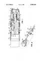
- FIG. 1is a side sectional view of a handpiece coupling according to this invention.
- FIG. 2is an exploded view of some of the internal elements of FIG. 1.
- the swivel coupling of this inventionis generally indicated at 2 and is shown attached to a handpiece indicated in phantom lines at 4 at the left end of the coupling.
- the right end of the couplingis connected to a supply hose, not shown, which supplies air, water and electrical wiring to the coupling.
- the handpiece swivel coupling 2may be considered as including a hose connector portion and a handpiece connector portion, one being rotatable or swivelable relative to the other.
- the hose connector portion of coupling 2includes a hose connector ring 6 which is adapted for threaded engagement with the supply hose.
- Connector ring 6carrys the ported body of a hose adaptor 8 which includes passages 10 and 12 for drive air and exhaust air respectively, such passages being in registry with corresponding conduits in the supply hose.
- the hose connector portion of the couplingalso includes an annular commutator ring 14 which is electrically connected by elongated pins 15 to a source of electrical current supplied through the supply hose.
- the connector ring 6is detachably connected by a bayonet fitting 16 to a disconnect ring 18.
- An O-ring 20 mounted on connector ring 6forms a sealing engagement with the interior of the disconnect ring 18.
- the handpiece connector portion of coupling 2includes a swivel tube 22 which includes a drive air passage (not shown) and exhaust air passage 12 in registry with corresponding passages in the handpiece 4.
- Swivel tube 22is surrounded by a handpiece connector ring 24 by which the coupling device is threaded to the handpiece 4.
- the disconnect ring 18is rotatably mounted to the handpiece connector ring 24 by means of a locking ring 26.
- Swivel tube 22further includes an axially extending cylindrical spool 23 which has a pair of sealed annular grooves communicating with air and water ports in the hose adaptor 8, and which spool 23 is internally ported to continue the water and air passages through swivel tube 22 and into corresponding conduits in handpiece 4.
- the handpiece connector ring 24, swivel tube 22 and spool 23are rotatable relative to hose connector ring 6, hose adaptor 8 and disconnect ring 18.
- Swivel tube 22includes a body 30 of thermally conductive material such as aluminum, body 30 in turn defining the passages for drive air (not shown), exhaust air 12, and a light aperture 32 which is in registry with an optical fiber bundle in the handpiece 4, which in turn directs light onto the handpiece work area.
- a lamp cavity 34is also formed in the conductive body 30. Lamp cavity 34 communicates with the annular cavity 12 which forms a part of exhaust air passage 12.
- a lamp 36is mounted within lamp cavity 34 to illuminate the light aperture 32 and the corresponding optical fiber bundle extending through the handpiece. Lamp 36 is inserted into a base 38 which includes spring loaded commutator contacts 40 in slidable electrical contact with commutator 14.
- FIG. 2shows in exploded view the electrical and lamp components of FIG. 1.
- FIG. 2also shows more clearly the location of the swivel plane 42, between lamp base 38 and commutator 14.
- exhaust air passage 12includes an annular portion surrounding the body 30 and communicating directly with the lamp cavity 34. Exhaust air from the turbine is thus directed over the lamp, over the lamp contacts, and over the conductive body 30 which acts as a heat sink. From the base of lamp 36, exhaust air continues through passage 12 back through the hose connector portion of the coupling and into the supply hose.
- the lamp base 38 and lamp 36Separation of the swivel coupling at the disconnect ring 18 and bayonet fitting 16 provides access to the lamp base 38 and lamp 36. Simply by grasping the base 38, the lamp can be removed from its cavity 34. Once lamp and base are removed, the lamp 36 is easily removable from the base 38 for low cost lamp replacement. In other words, the lamp 36 can be replaced when necessary without replacing the base 38. Conversely, the base 38 is individually replaceable.
- Electrical insulationis provided at required areas within the electrical system by hard coat anodizing of the various parts, which are made of an aluminum alloy.
Landscapes
- Health & Medical Sciences (AREA)
- Oral & Maxillofacial Surgery (AREA)
- Dentistry (AREA)
- Epidemiology (AREA)
- Life Sciences & Earth Sciences (AREA)
- Animal Behavior & Ethology (AREA)
- General Health & Medical Sciences (AREA)
- Public Health (AREA)
- Veterinary Medicine (AREA)
- Dental Tools And Instruments Or Auxiliary Dental Instruments (AREA)
Abstract
Description
Claims (1)
Priority Applications (1)
| Application Number | Priority Date | Filing Date | Title |
|---|---|---|---|
| US06/656,035US4600384A (en) | 1984-09-28 | 1984-09-28 | Swivel coupling for illuminated dental handpiece |
Applications Claiming Priority (1)
| Application Number | Priority Date | Filing Date | Title |
|---|---|---|---|
| US06/656,035US4600384A (en) | 1984-09-28 | 1984-09-28 | Swivel coupling for illuminated dental handpiece |
Publications (1)
| Publication Number | Publication Date |
|---|---|
| US4600384Atrue US4600384A (en) | 1986-07-15 |
Family
ID=24631366
Family Applications (1)
| Application Number | Title | Priority Date | Filing Date |
|---|---|---|---|
| US06/656,035Expired - LifetimeUS4600384A (en) | 1984-09-28 | 1984-09-28 | Swivel coupling for illuminated dental handpiece |
Country Status (1)
| Country | Link |
|---|---|
| US (1) | US4600384A (en) |
Cited By (24)
| Publication number | Priority date | Publication date | Assignee | Title |
|---|---|---|---|---|
| US4720266A (en)* | 1985-03-27 | 1988-01-19 | Micro-Mega S.A. | Dental treatment device |
| US4725231A (en)* | 1985-03-27 | 1988-02-16 | Micro-Mega S.A. | Dental-surgeon handpiece with battery lighting |
| EP0405206A1 (en)* | 1989-06-26 | 1991-01-02 | Bien-Air Sa | Device for conducting electric and air currents between a dental instrument and a coupling |
| EP0370998A3 (en)* | 1988-11-21 | 1991-01-23 | Dentalwerk Bürmoos Gesellschaft M.B.H. | Elbow coupling |
| US5033960A (en)* | 1990-11-05 | 1991-07-23 | Midwest Dental Products Corporation | Dental handpiece connector assembly with replaceable air-cooled lamp and insertion/extraction tool therefor |
| US5096418A (en)* | 1990-07-05 | 1992-03-17 | Micro Motors, Inc. | Motorized dental handpiece with fiber optic illumination |
| FR2673369A1 (en)* | 1991-02-28 | 1992-09-04 | Micro Mega Sa | DEVICE FOR CONNECTING DENTISTRY HANDPIECES PROVIDED WITH ELECTRICAL MEANS FOR LIGHTING THE WORKPLACE. |
| US5332389A (en)* | 1991-12-06 | 1994-07-26 | Imtec Innovative Medizintechnik Gesellschaft M.B.H. | Dental handpiece connecting portion receiving alternative illumination members |
| GB2292779A (en)* | 1994-08-30 | 1996-03-06 | Medident Ltd | Quick release swivel coupling for dental handpiece |
| US20020123021A1 (en)* | 2000-12-18 | 2002-09-05 | Dentsply Research & Development Corp. | Dental handpiece components |
| US20020124443A1 (en)* | 2000-12-18 | 2002-09-12 | Dentsply Research & Development Corp. | Metal-to-metal connections |
| US20030170589A1 (en)* | 2002-02-27 | 2003-09-11 | Novak Eugene J. | Dental handpiece with improved grease retention |
| US20030175654A1 (en)* | 2000-09-14 | 2003-09-18 | Dentsply Research & Development Corp. | Bearing for dental handpiece |
| US20030209072A1 (en)* | 2002-03-28 | 2003-11-13 | Lu He | Method and apparatus for balancing the rotating elements of a dental handpiece |
| US20060191336A1 (en)* | 2002-03-28 | 2006-08-31 | Dentsply Research & Development Corp. | Method and apparatus for balancing the rotating elements of a dental handpiece |
| US20060234186A1 (en)* | 2000-09-14 | 2006-10-19 | Novak Eugene J | Bearing for dental handpiece |
| US20070031786A1 (en)* | 2002-02-25 | 2007-02-08 | Heil Donald J | Dental handpiece |
| US20070059664A1 (en)* | 2000-09-14 | 2007-03-15 | Novak Eugene J | Bearing for dental handpiece |
| US20070117064A1 (en)* | 2002-02-27 | 2007-05-24 | Novak Eugene J | Dental handpiece with improved grease retention |
| US20080118890A1 (en)* | 2005-04-12 | 2008-05-22 | Spring Health Products, Inc. | Electric dental handpiece and control system |
| US20120052460A1 (en)* | 2010-08-30 | 2012-03-01 | Dentalez, Inc. | Dental handpiece swivel coupling with an autoclavable illuminator assembly |
| KR101281531B1 (en)* | 2012-02-14 | 2013-07-03 | 원텍 주식회사 | Medical laser delivery device |
| EP3015082A1 (en)* | 2014-10-31 | 2016-05-04 | Karl Storz GmbH & Co. KG | Dismountable medical instrument |
| US11166784B2 (en)* | 2020-10-16 | 2021-11-09 | Yong Weon Kim | Power generating system for a rotatory dental apparatus |
Citations (8)
| Publication number | Priority date | Publication date | Assignee | Title |
|---|---|---|---|---|
| DE1068425B (en)* | 1955-10-03 | |||
| US4260382A (en)* | 1980-01-23 | 1981-04-07 | Thomson Loronzo H | Air turbine dental handpieces and swivel connections therefor |
| US4334863A (en)* | 1980-03-11 | 1982-06-15 | Kinetic Instruments Inc. | Illuminator for dental handpiece |
| EP0070194A1 (en)* | 1981-07-15 | 1983-01-19 | Flemming Julin Hansen | Coupling assembly for a driven tool and a coupling for use therein |
| US4403959A (en)* | 1981-07-31 | 1983-09-13 | Kabushiki Kaisha Yoshida Seisakusho | Coupling device for a dental instrument |
| US4460337A (en)* | 1981-08-20 | 1984-07-17 | Siemens Aktiengesellschaft | Dental handpiece |
| US4514169A (en)* | 1983-09-09 | 1985-04-30 | Kaltenbach & Voigt Gmbh & Co. | Dental handpiece |
| US4518355A (en)* | 1982-04-23 | 1985-05-21 | Kaltenbach & Voigt Gmbh & Co. | Dental handpiece |
- 1984
- 1984-09-28USUS06/656,035patent/US4600384A/ennot_activeExpired - Lifetime
Patent Citations (9)
| Publication number | Priority date | Publication date | Assignee | Title |
|---|---|---|---|---|
| DE1068425B (en)* | 1955-10-03 | |||
| FR1161157A (en)* | 1955-10-03 | 1958-08-22 | Device for supplying electric current to handpieces, angle pieces and dental contra-angles with electric lighting | |
| US4260382A (en)* | 1980-01-23 | 1981-04-07 | Thomson Loronzo H | Air turbine dental handpieces and swivel connections therefor |
| US4334863A (en)* | 1980-03-11 | 1982-06-15 | Kinetic Instruments Inc. | Illuminator for dental handpiece |
| EP0070194A1 (en)* | 1981-07-15 | 1983-01-19 | Flemming Julin Hansen | Coupling assembly for a driven tool and a coupling for use therein |
| US4403959A (en)* | 1981-07-31 | 1983-09-13 | Kabushiki Kaisha Yoshida Seisakusho | Coupling device for a dental instrument |
| US4460337A (en)* | 1981-08-20 | 1984-07-17 | Siemens Aktiengesellschaft | Dental handpiece |
| US4518355A (en)* | 1982-04-23 | 1985-05-21 | Kaltenbach & Voigt Gmbh & Co. | Dental handpiece |
| US4514169A (en)* | 1983-09-09 | 1985-04-30 | Kaltenbach & Voigt Gmbh & Co. | Dental handpiece |
Cited By (36)
| Publication number | Priority date | Publication date | Assignee | Title |
|---|---|---|---|---|
| US4720266A (en)* | 1985-03-27 | 1988-01-19 | Micro-Mega S.A. | Dental treatment device |
| US4725231A (en)* | 1985-03-27 | 1988-02-16 | Micro-Mega S.A. | Dental-surgeon handpiece with battery lighting |
| EP0370998A3 (en)* | 1988-11-21 | 1991-01-23 | Dentalwerk Bürmoos Gesellschaft M.B.H. | Elbow coupling |
| US5074785A (en)* | 1988-11-21 | 1991-12-24 | Dentalwerk Burmoos Gesellschaft M.B.H. | Angle piece coupling |
| EP0405206A1 (en)* | 1989-06-26 | 1991-01-02 | Bien-Air Sa | Device for conducting electric and air currents between a dental instrument and a coupling |
| CH679007A5 (en)* | 1989-06-26 | 1991-12-13 | Bien Air | |
| US5096418A (en)* | 1990-07-05 | 1992-03-17 | Micro Motors, Inc. | Motorized dental handpiece with fiber optic illumination |
| US5033960A (en)* | 1990-11-05 | 1991-07-23 | Midwest Dental Products Corporation | Dental handpiece connector assembly with replaceable air-cooled lamp and insertion/extraction tool therefor |
| FR2673369A1 (en)* | 1991-02-28 | 1992-09-04 | Micro Mega Sa | DEVICE FOR CONNECTING DENTISTRY HANDPIECES PROVIDED WITH ELECTRICAL MEANS FOR LIGHTING THE WORKPLACE. |
| US5332389A (en)* | 1991-12-06 | 1994-07-26 | Imtec Innovative Medizintechnik Gesellschaft M.B.H. | Dental handpiece connecting portion receiving alternative illumination members |
| GB2292779A (en)* | 1994-08-30 | 1996-03-06 | Medident Ltd | Quick release swivel coupling for dental handpiece |
| GB2292779B (en)* | 1994-08-30 | 1998-06-10 | Medident Ltd | Adaptor for use with dentistry equipment |
| US20050130101A1 (en)* | 2000-09-14 | 2005-06-16 | Novak Eugene J. | Bearing for dental handpiece |
| US20060234186A1 (en)* | 2000-09-14 | 2006-10-19 | Novak Eugene J | Bearing for dental handpiece |
| US20080032261A1 (en)* | 2000-09-14 | 2008-02-07 | Novak Eugene J | Bearing for dental handpiece |
| US20030175654A1 (en)* | 2000-09-14 | 2003-09-18 | Dentsply Research & Development Corp. | Bearing for dental handpiece |
| US20070059664A1 (en)* | 2000-09-14 | 2007-03-15 | Novak Eugene J | Bearing for dental handpiece |
| US20070238067A1 (en)* | 2000-12-18 | 2007-10-11 | Tom Papanek | Dental handpiece components |
| US20020124443A1 (en)* | 2000-12-18 | 2002-09-12 | Dentsply Research & Development Corp. | Metal-to-metal connections |
| US20050202366A1 (en)* | 2000-12-18 | 2005-09-15 | Novak Eugene J. | Metal-to-metal connections |
| US20050198807A1 (en)* | 2000-12-18 | 2005-09-15 | Novak Eugene J. | Metal-to-metal connections |
| US20060194168A1 (en)* | 2000-12-18 | 2006-08-31 | Tom Papanek | Dental handpiece components |
| US20050037317A1 (en)* | 2000-12-18 | 2005-02-17 | Tom Papanek | Dental handpiece components |
| US20020123021A1 (en)* | 2000-12-18 | 2002-09-05 | Dentsply Research & Development Corp. | Dental handpiece components |
| US20070031786A1 (en)* | 2002-02-25 | 2007-02-08 | Heil Donald J | Dental handpiece |
| US20050287493A1 (en)* | 2002-02-27 | 2005-12-29 | Novak Eugene J | Dental handpiece with improved grease retention |
| US20030170589A1 (en)* | 2002-02-27 | 2003-09-11 | Novak Eugene J. | Dental handpiece with improved grease retention |
| US20070117064A1 (en)* | 2002-02-27 | 2007-05-24 | Novak Eugene J | Dental handpiece with improved grease retention |
| US20030209072A1 (en)* | 2002-03-28 | 2003-11-13 | Lu He | Method and apparatus for balancing the rotating elements of a dental handpiece |
| US20060191336A1 (en)* | 2002-03-28 | 2006-08-31 | Dentsply Research & Development Corp. | Method and apparatus for balancing the rotating elements of a dental handpiece |
| US20080202236A1 (en)* | 2002-03-28 | 2008-08-28 | Lu He | Method and apparatus for balancing the rotating elements of a dental handpiece |
| US20080118890A1 (en)* | 2005-04-12 | 2008-05-22 | Spring Health Products, Inc. | Electric dental handpiece and control system |
| US20120052460A1 (en)* | 2010-08-30 | 2012-03-01 | Dentalez, Inc. | Dental handpiece swivel coupling with an autoclavable illuminator assembly |
| KR101281531B1 (en)* | 2012-02-14 | 2013-07-03 | 원텍 주식회사 | Medical laser delivery device |
| EP3015082A1 (en)* | 2014-10-31 | 2016-05-04 | Karl Storz GmbH & Co. KG | Dismountable medical instrument |
| US11166784B2 (en)* | 2020-10-16 | 2021-11-09 | Yong Weon Kim | Power generating system for a rotatory dental apparatus |
Similar Documents
| Publication | Publication Date | Title |
|---|---|---|
| US4600384A (en) | Swivel coupling for illuminated dental handpiece | |
| US4681540A (en) | Dental handpiece arrangement | |
| US4477252A (en) | Fiber optic system for dental handpiece | |
| US4642738A (en) | Illuminated dental drill | |
| CA1091772A (en) | Welding gun having replaceable curved nozzle body | |
| JPH0319369Y2 (en) | ||
| JPH0736646Y2 (en) | Dental handpiece | |
| US4568284A (en) | Dental handpiece | |
| US4403136A (en) | Arc welding gun with handle assembly | |
| US4534734A (en) | Swivel dental handpiece | |
| US6855109B2 (en) | Portable endoscope | |
| US4330274A (en) | Lighting system for a dental handpiece | |
| US4507085A (en) | Dental instrument with handpiece | |
| US4534732A (en) | Dental handpiece | |
| US4655709A (en) | Coupling device for dental handpieces | |
| WO2012012533A1 (en) | Multi-purpose dental instrument | |
| JPH07250846A (en) | Disposable filter for dentistry hand piece | |
| US3496328A (en) | Welding gun | |
| US4431412A (en) | Dental handpiece | |
| US4561845A (en) | Illumination for dental drills | |
| US4804329A (en) | Connecting device for an illuminant handpiece | |
| US6159004A (en) | Instrument holder | |
| US5327880A (en) | Borescope | |
| US4680011A (en) | Dental contra-angle handpiece with means for illuminating the treatment area | |
| US20120189978A1 (en) | Ultrasonic dental insert and lighted handpiece assembly |
Legal Events
| Date | Code | Title | Description |
|---|---|---|---|
| AS | Assignment | Owner name:SYBRON CORPORATION, 1100MIDTOWN TOWER, ROCHESTER, Free format text:ASSIGNMENT OF ASSIGNORS INTEREST.;ASSIGNOR:OLSEN, ROBERT A.;REEL/FRAME:004331/0796 Effective date:19840924 | |
| STCF | Information on status: patent grant | Free format text:PATENTED CASE | |
| AS | Assignment | Owner name:NALGE COMPANY, A CORP OF DE Free format text:ASSIGNMENT OF ASSIGNORS INTEREST.;ASSIGNOR:SYBRON CORPORATION, A CORP. OF NY;REEL/FRAME:004628/0848 Effective date:19860731 | |
| FEPP | Fee payment procedure | Free format text:PAYOR NUMBER ASSIGNED (ORIGINAL EVENT CODE: ASPN); ENTITY STATUS OF PATENT OWNER: LARGE ENTITY | |
| AS | Assignment | Owner name:LAKE SHORE NATIONAL BANK, 605 NORTH MICHIGAN AVENU Free format text:SECURITY INTEREST;ASSIGNOR:MIDWEST DENTAL CORPORATION;REEL/FRAME:004816/0449 Effective date:19871218 Owner name:MIDWEST DENTAL CORPORATION, 901 WEST OAKTON, DES P Free format text:ASSIGNMENT OF ASSIGNORS INTEREST.;ASSIGNOR:NALGE COMPANY (A DE. CORP.);REEL/FRAME:004818/0867 Effective date:19871216 Owner name:MIDWEST DENTAL CORPORATION, A DE. CORP.,ILLINOIS Free format text:ASSIGNMENT OF ASSIGNORS INTEREST;ASSIGNOR:NALGE COMPANY (A DE. CORP.);REEL/FRAME:004818/0867 Effective date:19871216 | |
| FEPP | Fee payment procedure | Free format text:PAYER NUMBER DE-ASSIGNED (ORIGINAL EVENT CODE: RMPN); ENTITY STATUS OF PATENT OWNER: LARGE ENTITY Free format text:PAYOR NUMBER ASSIGNED (ORIGINAL EVENT CODE: ASPN); ENTITY STATUS OF PATENT OWNER: LARGE ENTITY | |
| FPAY | Fee payment | Year of fee payment:4 | |
| FEPP | Fee payment procedure | Free format text:PAYER NUMBER DE-ASSIGNED (ORIGINAL EVENT CODE: RMPN); ENTITY STATUS OF PATENT OWNER: LARGE ENTITY Free format text:PAYOR NUMBER ASSIGNED (ORIGINAL EVENT CODE: ASPN); ENTITY STATUS OF PATENT OWNER: LARGE ENTITY | |
| FPAY | Fee payment | Year of fee payment:8 | |
| AS | Assignment | Owner name:DENTSPLY RESEARCH & DEVELOPMENT CORP., DELAWARE Free format text:ASSIGNMENT OF ASSIGNORS INTEREST;ASSIGNOR:MIDWEST DENTAL PRODUCTS CORPORATION;REEL/FRAME:007152/0151 Effective date:19940920 | |
| FPAY | Fee payment | Year of fee payment:12 |