US4598840A - Snap-in cartridge diluter - Google Patents
Snap-in cartridge diluterDownload PDFInfo
- Publication number
- US4598840A US4598840AUS06/540,291US54029183AUS4598840AUS 4598840 AUS4598840 AUS 4598840AUS 54029183 AUS54029183 AUS 54029183AUS 4598840 AUS4598840 AUS 4598840A
- Authority
- US
- United States
- Prior art keywords
- piston
- fluid
- handling device
- cartridge
- fluid handling
- Prior art date
- Legal status (The legal status is an assumption and is not a legal conclusion. Google has not performed a legal analysis and makes no representation as to the accuracy of the status listed.)
- Expired - Fee Related
Links
- 239000012530fluidSubstances0.000claimsabstractdescription146
- 230000008878couplingEffects0.000claimsdescription31
- 238000010168coupling processMethods0.000claimsdescription31
- 238000005859coupling reactionMethods0.000claimsdescription31
- 238000007789sealingMethods0.000claimsdescription15
- 230000033001locomotionEffects0.000claimsdescription10
- 238000005086pumpingMethods0.000claimsdescription8
- 230000006872improvementEffects0.000claimsdescription7
- 238000004891communicationMethods0.000claimsdescription5
- 239000000523sampleSubstances0.000abstractdescription56
- 239000003153chemical reaction reagentSubstances0.000abstractdescription54
- 239000003085diluting agentSubstances0.000abstractdescription15
- 238000007865dilutingMethods0.000abstractdescription6
- 238000012423maintenanceMethods0.000abstractdescription2
- 238000010790dilutionMethods0.000abstract2
- 239000012895dilutionSubstances0.000abstract2
- 238000005070samplingMethods0.000abstract1
- 230000006870functionEffects0.000description8
- 239000004809TeflonSubstances0.000description7
- 229920006362Teflon®Polymers0.000description7
- 238000012360testing methodMethods0.000description6
- 229910000831SteelInorganic materials0.000description4
- 239000010959steelSubstances0.000description4
- 238000003860storageMethods0.000description4
- 238000005516engineering processMethods0.000description3
- 239000007788liquidSubstances0.000description3
- 230000004913activationEffects0.000description2
- 239000005388borosilicate glassSubstances0.000description2
- 230000006835compressionEffects0.000description2
- 238000007906compressionMethods0.000description2
- 238000011109contaminationMethods0.000description2
- 238000013461designMethods0.000description2
- 238000005259measurementMethods0.000description2
- 239000012528membraneSubstances0.000description2
- 239000000126substanceSubstances0.000description2
- 238000010998test methodMethods0.000description2
- CRCBRZBVCDKPGA-UHFFFAOYSA-N1,2,5-trichloro-3-(2,5-dichlorophenyl)benzeneChemical compoundClC1=CC=C(Cl)C(C=2C(=C(Cl)C=C(Cl)C=2)Cl)=C1CRCBRZBVCDKPGA-UHFFFAOYSA-N0.000description1
- 238000013459approachMethods0.000description1
- 238000004140cleaningMethods0.000description1
- 238000009429electrical wiringMethods0.000description1
- 239000011521glassSubstances0.000description1
- 238000003780insertionMethods0.000description1
- 230000037431insertionEffects0.000description1
- 238000009434installationMethods0.000description1
- 238000004519manufacturing processMethods0.000description1
- 239000000463materialSubstances0.000description1
- 239000011159matrix materialSubstances0.000description1
- 238000012986modificationMethods0.000description1
- 230000004048modificationEffects0.000description1
- 238000012552reviewMethods0.000description1
- 239000012898sample dilutionSubstances0.000description1
- 230000003068static effectEffects0.000description1
- 230000001360synchronised effectEffects0.000description1
Images


Classifications
- G—PHYSICS
- G01—MEASURING; TESTING
- G01N—INVESTIGATING OR ANALYSING MATERIALS BY DETERMINING THEIR CHEMICAL OR PHYSICAL PROPERTIES
- G01N1/00—Sampling; Preparing specimens for investigation
- G01N1/28—Preparing specimens for investigation including physical details of (bio-)chemical methods covered elsewhere, e.g. G01N33/50, C12Q
- G01N1/38—Diluting, dispersing or mixing samples
- G01N2001/382—Diluting, dispersing or mixing samples using pistons of different sections
Definitions
- This inventionrelates to the field of precision fluid pumping devices used primarily for diluting and dispensing of fluid samples and chemical reagents, and more particularly to the type of dilutor or dispenser having a removable fluid containing cartridge.
- This inventionconstitutes a significant improvement in diluting and dispensing devices used primarily for preparing samples in clinical laboratories, industrial laboratories, or anywhere that precision fluid measurement and delivery is required.
- commercially available reagent containing diluting deviceshave required separate reagent reservoirs, but normally feed a reagent pump through a valve or other sealing means.
- the valveopens to a separate reagent reservoir allowing the reagent pump, normally a syringe, to cycle and fill with reagent.
- the valvethen rotates to its discharge postion and the pump discharges the reagent, along with the sample picked up separately if in a sample dilution mode. Discharge is normally through a tube into the test receptacle.
- 3,982 667shows a removable reagent syringe diluter with concentric sample and reagent pistons whereby the sample piston actually passes through a seal in the reagent piston.
- Chen's approachutilizes the same concept of a single piston cylinder as does Glenn and Downings, et al., but Chen does teach the ability to work with small sample sizes since the disclosure includes a separate small sample piston.
- One disadvantage of Chenis that movement of the sample piston can dislodge the reagent piston, thereby causing significant volumetric errors in the sample size, and some error in reagent size.
- a further disadvantageis that a significant volume of reagent is unusable as the reagent piston must stop somewhat short of its cylinder upper end if the sample piston is to function along its full stroke.
- One more disadvantageis that there are limitations on the diameter of the reagent piston as a consequence of the geometry of the sample piston and its seals.
- the Chen conceptappears costly to manufacture and maintain by reason of its complexity.
- Glenn, Downings, et al., and Chenall teach cylinder fastening systems that are manual, requiring some operator dexterity, as opposed to the automatic cartridge attachment means of the present invention.
- the present inventionoffers all of the flexibility of programmable dilutors and dispensers combined with readily removable and storable, extreme accuracy, low cost, simple, fluid cartridges.
- a drive motoractually disconnects the cartridge automatically upon command to further simplify operation.
- a simple single piston versionis offered, primarily for dispensing reagents, which also utilizes the novel automatic cylinder attachment means of the present invention. Accordingly, the present invention offers substantial unique advantages over the prior art that are extremely valuable to the end user or operator. These advantages are described in significant detail in the following section.
- the cartridge pistonsremain with the cartridge when it is detached, thus sealing the cylinder for storage.
- the automatic piston attachment meanswhich connects the piston to a shaft is preferably accomplished with a magnetic coupling, although other means are feasible and have been tested.
- the cartridge elements in contact with fluidare normally borosilicate glass and Teflon * for maximum chemical compatibility. Seals are normally of Teflon with a resiliently biased backing or expanding member, such as an O-ring or spring, to account for the poor elastic memory of Teflon based materials.
- discharge and pickupis through a small bore Teflon tube that is affixed to the cartridge by a coupling nut.
- a spring or O-ringcan be used to aid tube sealing if required.
- the tubeis normally at least three feet (1 meter) long to allow for sample or other fluid pickup in the tube, although shorter lengths are feasible with increased tube or probe inside diameters.
- Actuation of machine functionsis normally accomplished by means of a switch located in a hand probe through which the tube passes. It is also feasible to use other fluid pickup and dispensing means. For example, a fixed probe can be attached to the cartridge and an actuation switch could then be located on the main unit body, attached as a separate foot switch, or the like.
- a unique featureis the novel automatic cartridge attachment means.
- Thisis preferably a resiliently biased locking element used for cartridge fastening or locking.
- This assemblyincludes at least one spring-loaded ball or other element forced into a locking position in a groove or pocket in a portion of the cartridge by a resiliently biased member.
- the main or reagent piston motorforces the resiliently biased member downward, thus releasing the balls and unfastening the cartridge. Force from the same motor separates the magnetic coupling used to affix the reagent piston in place to the motor shaft.
- Other coupling means for both the cartridge and pistonsare feasible, however, the magnetic coupling has been thoroughly tested in full working models by the inventor, has proved most effective, and has received strongly positive operator reviews.
- the primary candidates for piston drive meansare digital linear actuator motors which utilize a threaded shaft that passes through the motor. This motor concept offers unique installation advantages and results in a compact, low-profile diluter. Controlled electrical pulses applied to these motors result in precise linear movement of the shaft. Electrical control is normally from a microprocessor controller which receives operator programming input from a keyboard, preferably a liquid proof, sealed membrane switch.
- the operatorinputs a series of program steps which may include pickup (aspiration) of one or more samples, an air gap in the fluid pickup tube, pickup of one or more reagents, and dispensing of diluent (reagent in the main piston cylinder) along with all previous samples and/or reagents picked up in the probe or tube.
- pickupaspirration
- diluentreagent in the main piston cylinder
- Such “slave” diluterswould not contain the full compliment of electronics as the “stand alone” or primary diluter as generally described herein. Instead, these "slave” diluters receive commands from the primary diluter, or from other instruments or computers.
- Such "slave” diluters, including motors, cartridges, housing, etc.are comprised of identical components as the primary diluter.
- the main body elements of the present inventionmay also be incorporated into other types of machines.
- the inventionrepresents a significant improvement in fluid handling devices. It includes at least one main body element and at least one fluid container, usually including a plurality of pistons acting as fluid pumping means. These pistons are connected to and position controlled by precision distance moving means. The pistons are disposed sealingly within cylinders that are in fluid communication with fluid passage means, such as a tube, whereby piston movement accomplishes fluid pickup and discharge through the fluid passage means or tube.
- the focus of the improvementis a valveless fluid cartridge assembly having a separate piston cylinder for each piston, which assembly is readily detachable from the main body element in such a way that the separate pistons readily disconnect from the precision distance moving means and remain in the separate piston cylinders when this valveless fluid cartridge assembly is detached from the main body element.
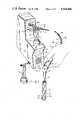
- FIG. 1is a perspective view showing the external working elements of the snap-in cartridge diluter according to the present invention, showing a fluid cartridge coupled in place, programming keyboard, display, control switches, hand probe and discharge tube, stand-alone fluid handling device body element, extra fluid cartridge and the type of receptacle test tube of a type frequently used with the invention.
- FIG. 2is a side view of the present invention with a fluid cartridge shown separated from the invention as removed therefrom, and having a side cover removed to show the main piston and sample piston activation motors, and electronic components.
- FIG. 3is a fractional centerline cross section of the top portion of a fluid cartridge showing the sample piston assembly, diluent or main cylinder, sample cylinder, interconnecting passageways, discharge tube and discharge tube coupling nut.
- FIG. 4is a fragmentary centerline cross section from the left to the center of the drawing, showing automatic cartridge attachment means and cartridge, including main piston assembly in the detached state.
- FIG. 5is also a fragmentary centerline cross section from the right to the center of the drawing including main cartridge assembly in the attached state.
- FIG. 1discloses a control or "stand alone" snap-in cartridge diluter 10 in the preferred embodimcnt of the present invention. It shows a cabinet or housing 41, diluter main body element 79, sample piston assembly 80, a readily detachable fluid containing cartridge 11, fluid dispensing tube 12 and tube retaining or coupling nut 28. It also shows an open end 91 of tube 12, electronic wire 15, its connector 17, tubing and wire clamps 16, hand probe 13 and hand probe actuator switch 14. The invention is used generally with a receptacle test tube 25, in which is contained test tube fluid 27, and in which can be seen a dispensed droplet 26.
- an extra cartridge 21which may be sealed with the air contained therein removed when placed in storage as, for example, in a refrigerated environment to retain diluent such as a reagent, or other fluids.
- Elements of the diluter 10 to interface with an operator thereofinclude a status light 20, programmable keyboard 19, function display 18, and release switch 93. Release switch 93 when actuated calls for automatic detachment of the cartridge 11.
- cartridge fill switch 94 and cartridge and tubing prime switch 95Filling is accomplished by drawing fluid from a separate fluid source through a fluid passageway such as tube 12.
- Other items showninclude the front of the sample piston digital linear actuator motor 22, motor lead screw 23, and magnetic coupling 24.
- Other types of couplingscan, of course, be used besides a permanent magnet as used in the magnetic coupling 24, and these can include both mechanical or electromechanical devices.
- the preferred embodimentincludes fluid passageway or tubing 12, remote hand held probe 13 with its body element 82, tube guide element 81, and actuator switch 14. Also shown is an operator's hand 83. It is possible to use a fixed pickup/discharge tube, simple flexible tube member, or the like, any of which may be attached to the cartridge 11 by a fastener such as coupling nut 28, or other fastening means. These discharge passage variations along with their required actuation means, such as a foot switch or diluter mounted actuator switch, are not shown as they are simple variations well known in the art.
- FIG. 2is a side view of the diluter 10, including housing 41, housing feet 40 and main body element 79.
- the near side panelhas been removed to show the general internal components, less electrical wiring for simplicity, of the diluter 10, with cartridge 11 detached.
- the preferred embodiment of cartridge 11includes a glass housing 31, label 32, cartridge base 33, tube nut 28, sample piston shaft 30, plated steel sample piston coupling element 29, and sample piston assembly 80. Also shown attached to the cartridge 11 are tubing 12, electrical wire 15, and electrical connector 17.
- drive motors 22 and 42Disposed within housing 41 are drive motors 22 and 42 which preferably are digital linear actuator motors with threaded shafts 23 and 39.
- the digital linear actuator motors 22 and 42position shafts 23 and 39 outwardly or inwardly in precise incremental amounts by electronic input control means. It is also possible to use other piston drive means such as synchronous or other type motors with shaft position encoders, nonextending shaft stepper motors, solenoid actuators, pneumatic actuators, or other piston movement means although these are not shown.
- the preferred embodiment digital linear actuator motors 22 and 42use shaft guide and anti-rotation collar guide passageways 34 and 73, shaft guide collars 36, end travel limit switches 35, and anti-rotation screw pins 37 that slide in slots 38.
- the reason for the antirotation screw pins 37 and collars 36is to provide guidance and to prevent rotation of the motor shafts 39 when the motor internal rotor, not shown, rotates, thereby insuring that shaft 39 motions are in axial directions only.
- loading meanssuch as springs 86 and 87, which are used to axially load shafts 39 of motors 22 and 42, thus removing backlash and improving piston positioning accuracy.
- Loading meanssuch as springs 86 and 87 can alternatively be located in other positions and may be part of the cartridge 11 assembly where said loading means, if located between cartridge housing 31 and sample piston assembly coupling member 29, for example, could also act as a force to hold sample piston assembly 80 in position against sample motor shaft 23 thereby eliminating the need for a coupling magnet 24.
- the same principlecan be applied to the main fluid piston assembly 78 hereinafter described in connection with FIGS. 4 and 5.
- a permanent magnet coupling for the sample pistonis comprised of permanent magnet 24 which is removably attached to plated steel sample piston coupling element 29 when in use.
- a similar couplingis used with the main fluid piston assembly 78 of FIGS. 4 and 5.
- the other coupling meansincludes fastener base 44 having balls 45 which interact with cartridge base 33 of cartridge 11.
- a sealed membrane keypad 19dot matrix light emitting diode (LED) display 18, front panel printed circuit board (PCB) 39, status light 20, main microprocessor mounted PCB 92 and its attachment screws 43, power supply 84, line cord 47, fuse 46 and cartridge release, fill, and prime switches 93, 94 and 95.
- optional connectors 76, 77such as standard RS 232 ports, each of which generally serve a different purpose.
- Oneacts as a jack for input commands from another instrument or computer, and the second relays commands to other slave diluters.
- the slave dilutersare similar in appearance and function to the basic control diluter 10 shown.
- slave diluterswhen used, are placed in series with a primary, or control, diluter 10 or other instrument in circumstances when a series of tests and/or different reagents or other fluids are required for a test procedure.
- a primary, or control, diluter 10 or other instrumentin circumstances when a series of tests and/or different reagents or other fluids are required for a test procedure.
- the basic diluter concept shown herecan be incorporated into the framework of larger instruments where, in most instances, only the readily detachable fluid cartridge 11 portion of the diluter would be visible to the operator.
- the vertical orientation of the main diluent piston cylinder and the orientation of the smaller piston cylindermay be varied to accomodate different applications and may, for instance, be horizontal, vertical or at any other angle required.
- FIG. 3shows a centerline cross section view of the preferred embodiment of the top portion of cartridge 11 showing the main reagent or diluent piston cylinder 58, diluent, reagent or other fluid 60, cartridge housing 31 which is preferably of borosilicate glass for chemical resistivity, interconnecting passageway 59 and discharge passageway 65.
- the latter passagewaysare normally part of cartridge housing 31 which may be comprised of more than one piece. These may include portions of separate components such as tubing or other elements if desired.
- sample piston cylinder 61sample piston assembly 80
- sample piston 62which is normally made of Teflon
- sample piston resilient biasing means 63such as an O-ring or spring
- sample piston shaft 30sample piston shaft 30
- piston retaining protrusionssuch as knobs or rings 64 on sample piston shaft 30.
- the sample piston assembly 80normally includes all elements affixed to shaft 30. If driven to the discharge passageway 65 end of piston cylinder 61, sample piston 62 acts as a static seal.
- another acceptable arrangementutilizes a piston pumping assembly comprised of a precision diameter piston rod that normally has substantial clearance between itself and a piston cylinder 61. Sealing of this moveable piston rod is normally done with a seal fixed in position in the cartridge 11.
- FIG. 3Further illustrated in FIG. 3 are means of attaching and sealing a fluid passageway or tube 12 to the cartridge 11. These means may include a threaded bushing 66 affixed to cartridge housing 31, threaded tube nut 28, and resilient compression member 68 which is preferably an O-ring or spring. For storage, with tube 12 removed, a round blank Teflon sealing cover (not shown) is normally inserted under tube coupling nut 28.
- the sample piston 62is retracted to create a suction at the opened end (91 of FIG. 1) of tube 12. With the tube end immersed, this suction aspirates a fluid such as sample or reagent (27 of FIG. 1) from a test tube (25 of FIG. 1) or other container, or air if removed from the liquid, back into tube 12 in a precise amount. When dispensing, the sample piston 62 moves back outward the distance it was retracted. It is also feasible to use this concept without a sample piston cylinder 61 or sample piston 62, in which case the main cylinder 58 and piston assembly (78 of FIG. 4) would handle all fluid 60 pumping functions.
- the coupling nut assembly 67is normally concentric with the main reagent piston cylinder 58. Also, the sample piston activation motor (22 of FIG. 2) and its related hardware may be eliminated in such a case.
- FIG. 4displays a fragmentary centerline cross section, taken to the center 74 of the drawing, that shows a preferred design of the cartridge 11 which is fully in position, but wherein the coupling means is retracted.
- the piston coupling elementmay include a leak directing lip 75 on its lower edge so that any leakage will be directed to the leakage reservoir 50 in a movable locking means actuation member such as ball actuating cup 48.
- the ball actuating cup 48is resiliently loaded upward by biasing member 49, normally a spring.
- motor shaft 39moves outward allowing the ball actuating cup 48 to move upward, which because of sloped outer surfaces forces movable element locking means such as balls 45 outward in track 52 in fastener base 44, thereby locking balls 45 into position in latching pockets or grooves 85 in cartridge base 33.
- the fastener base 44is attached to the motor housing 46 by typical screw 69.
- the cartridge base 33is either a part of or is rigidly affixed to cartridge 11.
- the main fluid piston assembly 78is comprised of piston outer housing 55 which is normally made of Teflon and resiliently biased by O-ring or spring 57 and optional magnetic holding insert 54 which contains magnet 53. It is also, of course, possible to utilize other coupling means which may include electromagnets, mechanical or electromechanical means, among others.
- the diluent piston assembly 78is disposed within main diluent or reagent piston cylinder 58, which in turn is part of cartridge housing 31 and dispenses precise amounts of a fluid such as the reagent 60 when moved outward.
- a marking ring 72is provided in the fastener base 44 so that an operator can detect if cartridge 11 is properly seated on the fastener base 44.
- FIG. 5is a fragmentary cross section mirror image of FIG. 4 up to the center of the drawing 74, except that it shows the cartridge 11 in a coupled or fastened state in which it is firmly locked in position by outwardly disposed balls 45. Shown are all of the same elements as FIG. 4, but with the shaft 39 extended, coupling permanent magnet 53 firmly affixed to plated steel piston coupling element 51 and the outer surfaces of ball actuating cup 48 raised by spring 49 to press outward balls 45 in track 52 and lock them into position in latching pockets or grooves 85 in cartridge base 33.
- the main reagent, diluent, or fluid piston assembly 78is driven outward by motor 42 in precise amounts to dispense a fluid such as diluent or reagent 60.
- a fluidsuch as diluent or reagent 60.
- the piston assembly 78is drawn inward with the open end (91 of FIG. 1) of tube 12 in a fluid.
- Other elements included in FIG. 5are main piston cylinder 58, fluid such as reagent 60, main piston assembly 78, piston outer housing 55, piston ring or seal 56, seal resilient compression member 57, permanent magnet housing 54, motor 42, motor housing 46, motor bearing 47, and typical screw 69 that attaches fastener base 44 to motor 42.
Landscapes
- Physics & Mathematics (AREA)
- Health & Medical Sciences (AREA)
- Life Sciences & Earth Sciences (AREA)
- Chemical & Material Sciences (AREA)
- Analytical Chemistry (AREA)
- Biochemistry (AREA)
- General Health & Medical Sciences (AREA)
- General Physics & Mathematics (AREA)
- Immunology (AREA)
- Pathology (AREA)
- Automatic Analysis And Handling Materials Therefor (AREA)
Abstract
Description
Claims (50)
Priority Applications (2)
| Application Number | Priority Date | Filing Date | Title |
|---|---|---|---|
| US06/540,291US4598840A (en) | 1983-10-11 | 1983-10-11 | Snap-in cartridge diluter |
| AU36102/84AAU3610284A (en) | 1983-10-11 | 1984-10-23 | Snap-in cartridge diluter |
Applications Claiming Priority (1)
| Application Number | Priority Date | Filing Date | Title |
|---|---|---|---|
| US06/540,291US4598840A (en) | 1983-10-11 | 1983-10-11 | Snap-in cartridge diluter |
Publications (1)
| Publication Number | Publication Date |
|---|---|
| US4598840Atrue US4598840A (en) | 1986-07-08 |
Family
ID=24154827
Family Applications (1)
| Application Number | Title | Priority Date | Filing Date |
|---|---|---|---|
| US06/540,291Expired - Fee RelatedUS4598840A (en) | 1983-10-11 | 1983-10-11 | Snap-in cartridge diluter |
Country Status (2)
| Country | Link |
|---|---|
| US (1) | US4598840A (en) |
| AU (1) | AU3610284A (en) |
Cited By (22)
| Publication number | Priority date | Publication date | Assignee | Title |
|---|---|---|---|---|
| US4821586A (en)* | 1988-02-25 | 1989-04-18 | Medical Laboratory Automation, Inc. | Programmable pipette |
| US4905526A (en)* | 1984-02-16 | 1990-03-06 | Rainin Instrument Co., Inc. | Portable automated pipette for accurately pipetting and/or titrating liquids |
| EP0337460A3 (en)* | 1988-04-15 | 1990-06-27 | Przedsiebiorstwo Polonijno Zagraniczne Plastomed | A fluid dispensing device |
| US4942290A (en)* | 1988-12-27 | 1990-07-17 | Fawn Engineering Corp. | Dispensing machine having horizontal product carrier movable through an elliptical-type path |
| US4967606A (en)* | 1988-04-29 | 1990-11-06 | Caveo Scientific Instruments, Inc. | Method and apparatus for pipetting liquids |
| WO1996008440A1 (en)* | 1994-09-12 | 1996-03-21 | Philip Fishman Corporation | Electronically controlled, positive-displacement fluid dispenser |
| WO1999040444A1 (en)* | 1998-02-06 | 1999-08-12 | Bio-Magnetics Ltd. | A device and system for transfer of material |
| US20020083995A1 (en)* | 2000-04-25 | 2002-07-04 | Dudek David Robert | Product delivery system |
| US20020091596A1 (en)* | 2000-04-25 | 2002-07-11 | Dudek David Robert | Process and system for the customisation of consumer products |
| US6506611B2 (en)* | 1998-08-07 | 2003-01-14 | Deutsches Resourcenzentrum Fur Genomforschung Gmbh | Metering head for parallel processing of a plurality of fluid samples |
| US6598631B2 (en) | 2000-04-25 | 2003-07-29 | Shell Oil Company | Device and process for product reconstitution |
| US20040074318A1 (en)* | 2002-07-31 | 2004-04-22 | Drummond Scientific Company | Foot-operated pipette dispenser |
| US6734026B1 (en)* | 1999-05-28 | 2004-05-11 | Drummond Scientific Company | Pipette gun and holster assembly |
| US20050036919A1 (en)* | 2003-08-14 | 2005-02-17 | Hodson Steve J. | Syringe pump |
| US20060038359A1 (en)* | 2004-08-17 | 2006-02-23 | Luckenbaugh Thomas L | Keyless chuck with automatic and manual locking |
| US20060104866A1 (en)* | 2000-06-26 | 2006-05-18 | Vistalab Technologies, Inc. | Automatic pipette identification and detipping |
| US7066215B1 (en) | 2000-04-25 | 2006-06-27 | Shell Oil Company | Method for product mixing |
| US7416704B2 (en)* | 2000-06-26 | 2008-08-26 | Vistalab Technologies, Inc. | Handheld pipette |
| USD620602S1 (en) | 2008-01-03 | 2010-07-27 | Vistalab Technologies, Inc. | Pipette |
| US20130253537A1 (en)* | 2004-05-07 | 2013-09-26 | Usgi Medical, Inc. | Apparatus and methods for rapid deployment of tissue anchors |
| US8740022B2 (en) | 2012-02-15 | 2014-06-03 | Ecolab Usa Inc. | Volumetric metering device |
| US20180154390A1 (en)* | 2016-11-23 | 2018-06-07 | Fishman Corporation | Pencil gun |
Citations (21)
| Publication number | Priority date | Publication date | Assignee | Title |
|---|---|---|---|---|
| US2966175A (en)* | 1958-07-14 | 1960-12-27 | Central Scientific Co | Motor-driven syringe |
| US3032359A (en)* | 1958-05-05 | 1962-05-01 | Crawford Fitting Co | Quick connect coupling |
| US3138290A (en)* | 1962-08-31 | 1964-06-23 | Coulter Electronics | Automatic diluting apparatus |
| US3242881A (en)* | 1963-08-07 | 1966-03-29 | Schafer Leonhard | Patterned pastry making machine |
| US3419051A (en)* | 1966-11-17 | 1968-12-31 | Bert M. Gustafson | Density gradient system |
| US3446400A (en)* | 1967-01-25 | 1969-05-27 | American Hospital Supply Corp | Plural source fluid dispenser with interconnected discharge volume varying means |
| US3567398A (en)* | 1968-10-23 | 1971-03-02 | Farr Devices Inc | Semi-automatic pipetting and diluter device |
| US3748911A (en)* | 1970-12-29 | 1973-07-31 | Hoffmann La Roche | Device for taking samples of liquid specimens especially for the automatic analysis apparatus |
| US3800984A (en)* | 1971-11-26 | 1974-04-02 | Rohe Scientific Corp | Sampler and diluter |
| US3915651A (en)* | 1972-09-22 | 1975-10-28 | Us Government | Direct digital control pipette |
| US3924654A (en)* | 1973-12-26 | 1975-12-09 | Hughes Aircraft Co | Quick disconnect tank coupler |
| US3931915A (en)* | 1973-10-10 | 1976-01-13 | Micromedic Systems, Inc. | Liquid-containing cartridge and a device for dispensing measured amount of liquid from such a cartridge |
| US3955930A (en)* | 1975-04-07 | 1976-05-11 | Justin Joel Shapiro | Automatic dilutor having coupled diluent and reagent plungers |
| US3982667A (en)* | 1975-11-24 | 1976-09-28 | Hyperion Incorporated | Diluting liquid samples |
| US4101283A (en)* | 1976-07-13 | 1978-07-18 | Karl Erik Sundstrom | Disposable reagent container and actuation mechanism |
| US4155490A (en)* | 1977-07-05 | 1979-05-22 | Beckman Instruments, Inc. | Fluid dispenser |
| US4223558A (en)* | 1976-12-23 | 1980-09-23 | Beckman Instruments, Gmbh | Pipetting and diluting apparatus |
| US4241018A (en)* | 1978-09-15 | 1980-12-23 | Mettler Instrumente Ag | Apparatus with exchangeable burettes |
| US4429583A (en)* | 1981-03-31 | 1984-02-07 | Chugai Seiyaku Kabushiki Kaisha | Liquid uptake and discharge apparatus |
| US4471888A (en)* | 1981-07-20 | 1984-09-18 | Hilti Aktiengesellschaft | Device for dispensing measured amounts of multi-component materials |
| US4475666A (en)* | 1981-08-31 | 1984-10-09 | American Hospital Supply Corporation | Automated liquid dispenser control |
- 1983
- 1983-10-11USUS06/540,291patent/US4598840A/ennot_activeExpired - Fee Related
- 1984
- 1984-10-23AUAU36102/84Apatent/AU3610284A/ennot_activeAbandoned
Patent Citations (21)
| Publication number | Priority date | Publication date | Assignee | Title |
|---|---|---|---|---|
| US3032359A (en)* | 1958-05-05 | 1962-05-01 | Crawford Fitting Co | Quick connect coupling |
| US2966175A (en)* | 1958-07-14 | 1960-12-27 | Central Scientific Co | Motor-driven syringe |
| US3138290A (en)* | 1962-08-31 | 1964-06-23 | Coulter Electronics | Automatic diluting apparatus |
| US3242881A (en)* | 1963-08-07 | 1966-03-29 | Schafer Leonhard | Patterned pastry making machine |
| US3419051A (en)* | 1966-11-17 | 1968-12-31 | Bert M. Gustafson | Density gradient system |
| US3446400A (en)* | 1967-01-25 | 1969-05-27 | American Hospital Supply Corp | Plural source fluid dispenser with interconnected discharge volume varying means |
| US3567398A (en)* | 1968-10-23 | 1971-03-02 | Farr Devices Inc | Semi-automatic pipetting and diluter device |
| US3748911A (en)* | 1970-12-29 | 1973-07-31 | Hoffmann La Roche | Device for taking samples of liquid specimens especially for the automatic analysis apparatus |
| US3800984A (en)* | 1971-11-26 | 1974-04-02 | Rohe Scientific Corp | Sampler and diluter |
| US3915651A (en)* | 1972-09-22 | 1975-10-28 | Us Government | Direct digital control pipette |
| US3931915A (en)* | 1973-10-10 | 1976-01-13 | Micromedic Systems, Inc. | Liquid-containing cartridge and a device for dispensing measured amount of liquid from such a cartridge |
| US3924654A (en)* | 1973-12-26 | 1975-12-09 | Hughes Aircraft Co | Quick disconnect tank coupler |
| US3955930A (en)* | 1975-04-07 | 1976-05-11 | Justin Joel Shapiro | Automatic dilutor having coupled diluent and reagent plungers |
| US3982667A (en)* | 1975-11-24 | 1976-09-28 | Hyperion Incorporated | Diluting liquid samples |
| US4101283A (en)* | 1976-07-13 | 1978-07-18 | Karl Erik Sundstrom | Disposable reagent container and actuation mechanism |
| US4223558A (en)* | 1976-12-23 | 1980-09-23 | Beckman Instruments, Gmbh | Pipetting and diluting apparatus |
| US4155490A (en)* | 1977-07-05 | 1979-05-22 | Beckman Instruments, Inc. | Fluid dispenser |
| US4241018A (en)* | 1978-09-15 | 1980-12-23 | Mettler Instrumente Ag | Apparatus with exchangeable burettes |
| US4429583A (en)* | 1981-03-31 | 1984-02-07 | Chugai Seiyaku Kabushiki Kaisha | Liquid uptake and discharge apparatus |
| US4471888A (en)* | 1981-07-20 | 1984-09-18 | Hilti Aktiengesellschaft | Device for dispensing measured amounts of multi-component materials |
| US4475666A (en)* | 1981-08-31 | 1984-10-09 | American Hospital Supply Corporation | Automated liquid dispenser control |
Cited By (32)
| Publication number | Priority date | Publication date | Assignee | Title |
|---|---|---|---|---|
| US4905526A (en)* | 1984-02-16 | 1990-03-06 | Rainin Instrument Co., Inc. | Portable automated pipette for accurately pipetting and/or titrating liquids |
| US4821586A (en)* | 1988-02-25 | 1989-04-18 | Medical Laboratory Automation, Inc. | Programmable pipette |
| EP0337460A3 (en)* | 1988-04-15 | 1990-06-27 | Przedsiebiorstwo Polonijno Zagraniczne Plastomed | A fluid dispensing device |
| US4976161A (en)* | 1988-04-15 | 1990-12-11 | Przedsiebiorstwo Polonijno-Zagraniczne Plastomed | Fluid dispensing device |
| US4967606A (en)* | 1988-04-29 | 1990-11-06 | Caveo Scientific Instruments, Inc. | Method and apparatus for pipetting liquids |
| US4942290A (en)* | 1988-12-27 | 1990-07-17 | Fawn Engineering Corp. | Dispensing machine having horizontal product carrier movable through an elliptical-type path |
| WO1996008440A1 (en)* | 1994-09-12 | 1996-03-21 | Philip Fishman Corporation | Electronically controlled, positive-displacement fluid dispenser |
| US5630527A (en)* | 1994-09-12 | 1997-05-20 | Philip Fishman Corporation | Electronically controlled, positive-displacement fluid dispenser |
| WO1999040444A1 (en)* | 1998-02-06 | 1999-08-12 | Bio-Magnetics Ltd. | A device and system for transfer of material |
| US6409925B1 (en) | 1998-02-06 | 2002-06-25 | Bio-Magnetics Ltd. | Device and system for transfer of material |
| US6506611B2 (en)* | 1998-08-07 | 2003-01-14 | Deutsches Resourcenzentrum Fur Genomforschung Gmbh | Metering head for parallel processing of a plurality of fluid samples |
| US6734026B1 (en)* | 1999-05-28 | 2004-05-11 | Drummond Scientific Company | Pipette gun and holster assembly |
| US20020083995A1 (en)* | 2000-04-25 | 2002-07-04 | Dudek David Robert | Product delivery system |
| US20020091596A1 (en)* | 2000-04-25 | 2002-07-11 | Dudek David Robert | Process and system for the customisation of consumer products |
| US6598631B2 (en) | 2000-04-25 | 2003-07-29 | Shell Oil Company | Device and process for product reconstitution |
| US20060059866A1 (en)* | 2000-04-25 | 2006-03-23 | Dudek David R | Product delivery system |
| US7065940B2 (en) | 2000-04-25 | 2006-06-27 | Shell Oil Company | Product delivery system |
| US7066215B1 (en) | 2000-04-25 | 2006-06-27 | Shell Oil Company | Method for product mixing |
| US7416704B2 (en)* | 2000-06-26 | 2008-08-26 | Vistalab Technologies, Inc. | Handheld pipette |
| US20060104866A1 (en)* | 2000-06-26 | 2006-05-18 | Vistalab Technologies, Inc. | Automatic pipette identification and detipping |
| US8114362B2 (en) | 2000-06-26 | 2012-02-14 | Vistalab Technologies, Inc. | Automatic pipette identification |
| US6997068B2 (en)* | 2002-07-31 | 2006-02-14 | Drummond Scientific Company | Foot-operated pipette dispenser |
| US20040074318A1 (en)* | 2002-07-31 | 2004-04-22 | Drummond Scientific Company | Foot-operated pipette dispenser |
| US20050036919A1 (en)* | 2003-08-14 | 2005-02-17 | Hodson Steve J. | Syringe pump |
| US7311879B2 (en)* | 2003-08-14 | 2007-12-25 | Hodson Steve J | Syringe pump |
| US10441450B2 (en)* | 2004-05-07 | 2019-10-15 | Usgi Medical, Inc. | Apparatus and methods for rapid deployment of tissue anchors |
| US20130253537A1 (en)* | 2004-05-07 | 2013-09-26 | Usgi Medical, Inc. | Apparatus and methods for rapid deployment of tissue anchors |
| US20060038359A1 (en)* | 2004-08-17 | 2006-02-23 | Luckenbaugh Thomas L | Keyless chuck with automatic and manual locking |
| USD620602S1 (en) | 2008-01-03 | 2010-07-27 | Vistalab Technologies, Inc. | Pipette |
| US8740022B2 (en) | 2012-02-15 | 2014-06-03 | Ecolab Usa Inc. | Volumetric metering device |
| US20180154390A1 (en)* | 2016-11-23 | 2018-06-07 | Fishman Corporation | Pencil gun |
| US10286419B2 (en)* | 2016-11-23 | 2019-05-14 | Fishman Corporation | Pencil gun |
Also Published As
| Publication number | Publication date |
|---|---|
| AU3610284A (en) | 1986-05-15 |
Similar Documents
| Publication | Publication Date | Title |
|---|---|---|
| US4598840A (en) | Snap-in cartridge diluter | |
| US4475666A (en) | Automated liquid dispenser control | |
| US4311667A (en) | Delivering apparatus | |
| US4228831A (en) | Probe and syringe drive apparatus | |
| EP2477034B1 (en) | Dispensing device and analysis device | |
| US6739478B2 (en) | Precision fluid dispensing system | |
| US6180061B1 (en) | Moving platform slide stainer with heating elements | |
| US10962991B2 (en) | Modular multi-channel syringe pump | |
| US4528161A (en) | Probe for automated liquid dispenser | |
| JPH0247705B2 (en) | ||
| US5567122A (en) | Cylinder pump having controllable piston/drive detachment | |
| CA2600682A1 (en) | Precision fluid dispensing system | |
| CN116106236A (en) | Priming device and medical equipment | |
| US4428511A (en) | Fluid handling apparatus having a fluid metering volume therein | |
| US4120202A (en) | Positive displacement pump | |
| US3982667A (en) | Diluting liquid samples | |
| EP0159657A1 (en) | Cylinder pump | |
| US20030066364A1 (en) | Pipette head appatatus for robot | |
| WO1986002626A1 (en) | Snap-in cartridge diluter | |
| EP0070571A2 (en) | Automated liquid dispenser control | |
| CN114236161A (en) | Liquid suction structure and liquid supply device for immunoassay | |
| US6884231B1 (en) | Dual chambered fluid displacement apparatus | |
| KR102391790B1 (en) | Liquid discharging device, coating device provided with copper discharging device, and coating method therefor | |
| US4476999A (en) | Automated liquid dispenser | |
| US6092995A (en) | High precision pump for medical and chemical analyzers |
Legal Events
| Date | Code | Title | Description |
|---|---|---|---|
| AS | Assignment | Owner name:BURG NICOLE RENEE SIX (6%) PERCENT OF THE WHOLE IN Free format text:ASSIGNS TO EACH ASSIGNEE THE PERCENTAGE OPPOSITE THEIR NAME;ASSIGNOR:BURG, DONALD E.;REEL/FRAME:004184/0742 Effective date:19831007 Owner name:BURG SHERI RENEE SIX (6%) PERCENT OF THE WHOLE INV Free format text:ASSIGNS TO EACH ASSIGNEE THE PERCENTAGE OPPOSITE THEIR NAME;ASSIGNOR:BURG, DONALD E.;REEL/FRAME:004184/0742 Effective date:19831007 Owner name:BURG PAULETTE RENEE FORTY-ONE (41%) PERCENT OF THE Free format text:ASSIGNS TO EACH ASSIGNEE THE PERCENTAGE OPPOSITE THEIR NAME;ASSIGNOR:BURG, DONALD E.;REEL/FRAME:004184/0742 Effective date:19831007 Owner name:BURG DANIEL EARL SIX (6%) PERCENT OF THE WHOLE INV Free format text:ASSIGNS TO EACH ASSIGNEE THE PERCENTAGE OPPOSITE THEIR NAME;ASSIGNOR:BURG, DONALD E.;REEL/FRAME:004184/0742 Effective date:19831007 | |
| FEPP | Fee payment procedure | Free format text:PAYOR NUMBER ASSIGNED (ORIGINAL EVENT CODE: ASPN); ENTITY STATUS OF PATENT OWNER: SMALL ENTITY Free format text:PAYER NUMBER DE-ASSIGNED (ORIGINAL EVENT CODE: RMPN); ENTITY STATUS OF PATENT OWNER: SMALL ENTITY | |
| REMI | Maintenance fee reminder mailed | ||
| FPAY | Fee payment | Year of fee payment:4 | |
| SULP | Surcharge for late payment | ||
| REMI | Maintenance fee reminder mailed | ||
| LAPS | Lapse for failure to pay maintenance fees | ||
| FP | Lapsed due to failure to pay maintenance fee | Effective date:19940713 | |
| STCH | Information on status: patent discontinuation | Free format text:PATENT EXPIRED DUE TO NONPAYMENT OF MAINTENANCE FEES UNDER 37 CFR 1.362 |