US4597249A - Method of forming roll bales - Google Patents
Method of forming roll balesDownload PDFInfo
- Publication number
- US4597249A US4597249AUS06/694,868US69486885AUS4597249AUS 4597249 AUS4597249 AUS 4597249AUS 69486885 AUS69486885 AUS 69486885AUS 4597249 AUS4597249 AUS 4597249A
- Authority
- US
- United States
- Prior art keywords
- bale
- roll
- guide member
- indexing guide
- home position
- Prior art date
- Legal status (The legal status is an assumption and is not a legal conclusion. Google has not performed a legal analysis and makes no representation as to the accuracy of the status listed.)
- Expired - Lifetime
Links
Images


Classifications
- A—HUMAN NECESSITIES
- A01—AGRICULTURE; FORESTRY; ANIMAL HUSBANDRY; HUNTING; TRAPPING; FISHING
- A01F—PROCESSING OF HARVESTED PRODUCE; HAY OR STRAW PRESSES; DEVICES FOR STORING AGRICULTURAL OR HORTICULTURAL PRODUCE
- A01F15/00—Baling presses for straw, hay or the like
- A01F15/07—Rotobalers, i.e. machines for forming cylindrical bales by winding and pressing
- A01F15/0705—Arrangements for continuous operation
Definitions
- This inventionrelates generally to a method of continuously forming roll bales of crop material in a roll baler while moving across a field without stopping to discharge such bales from the roll baler.
- a method of this general typeis disclosed in U.S. Pat. No. 4,045,947 granted Sept. 6, 1977, to Aquila D. Mast and assigned to the same assignee as the present application.
- the roll baler disclosed in this patentincludes a lower bale forming apron and a pair of upper bale forming aprons.
- the upper bale forming apronscooperate with the lower bale forming apron to define front and rear bale forming chambers.
- a bale started in the front chamberreaches a predetermined size, it is transferred to the rear chamber where it is completed. While the completed roll bale is being wrapped with twine and discharged from the rear chamber, another bale is started in the front chamber. This provides for continuous baling operation.
- a drawback of the method of bale formation disclosed in U.S. Pat. No. 4,045,947is that roll bales tend to fall apart during transfer from the front chamber to the rear chamber.
- the present inventionprovides a method of forming roll bales in a roll baler having upper and lower bale forming means cooperating to define a bale starting zone.
- the upper bale forming meansextends around an indexing guide member which is located in a home position for disposing the upper bale forming means proximate to the lower bale forming means at the rear of the bale starting zone.
- the indexing guide memberis held in its home position while a first roll bale is started in the bale starting zone.
- the indexing guide memberis moved in a substantially circular path of travel generally about the periphery of the first roll bale.
- the indexing guide memberis returned to its home position after one full revolution around the circular path of travel.
- the indexing guide memberis then held in its home position while the first roll bale is discharged from the roll baler and a second roll bale is simultaneously started in the bale starting zone.
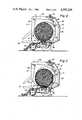
- FIG. 1is a side view of a roll baler embodying the present invention as a roll bale is being started;
- FIG. 2is a side view of the roll baler of FIG. 1 when a roll bale of predetermined diameter has been formed;
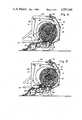
- FIG. 3is a side view of the roll baler of FIG. 1 during completion of a roll bale
- FIG. 4is another side view of the roll baler of FIG. 1 as a roll bale is being completed;
- FIG. 5is a side view of the roll baler of FIG. 1 when one roll bale has been completed and another roll bale is being started;
- FIG. 6is a side view of the roll baler of FIG. 1 during discharge of a completed roll bale.
- a roll baler 10is similar to the type disclosed in U.S. Pat. No. 3,914,926 granted Oct. 28, 1975, to Benjamin A. Braunberger et al and incorporated herein by reference.
- the type of baler disclosed in this patenthas been manufactured and sold by Gehl Company as Model Nos. 1400 and 1600.
- the roll baler 10includes a main body portion or frame 12 supported by a pair of wheels 14, and an auxiliary body portion or tailgate 16.
- a tongue 18is provided on the frame 12 for connection to a tractor.
- a pickup device 20 mounted on the frame 12includes a plurality of tines 22 rotatable about a shaft 23 for engaging and picking up crop material arranged in windrows on the ground.
- the frame 12includes a pair of sidewalls 13 which are vertically oriented and spaced apart.
- the tailgate 16includes a pair of side members 17 rigidly connected together by cross members (not shown).
- the side members 17 of the tailgate 16are pivotally connected by stub shafts 24 to the sidewalls 13 of the frame 12.
- a pair of hydraulic cylinders 26are connected between the sidewalls 13 of the frame 12 and the side members 17 of the tailgate 16 for moving the tailgate 16 between the closed position shown in FIG. 1 and the open position shown in FIG. 6.
- Lower bale forming meanssuch as a conveyor 28 in the form of an endless belt extends between the sidewalls 13 of the frame 12 and is supported on front and rear rollers 30 and 32, respectively, which are rotatably carried on the frame 12.
- the upper run 29 of the conveyor 28is supported between the front and rear rollers 30,32 by intermediate rollers 34 and 36 which are also rotatably carried on the frame 12.
- a press roller 38extends between and is supported on the sidewalls 13 of the frame 12 directly above the front roller 30 of the conveyor 28 to compress incoming crop material into a mat.
- the press roller 38 and the front roller 30 of the conveyor 28are connected by conventional drive means (not shown), such as chains and sprockets, to the power take off unit (PTO) of a tractor in a manner to cause rotation of the press roller 38 and the conveyor front roller 30 in the directions indicated in FIG. 1.
- the upper run 29 of the conveyor 28moves rearward from the front roller 30 to the rear roller 32.
- a plurality of guide members or rollers 40,42,44 and 46extend between and are rotatably supported on the sidewalls 13 of the frame 12.
- Another plurality of guide members or rollers 48,50,52,54,56 and 58extend between and are rotatably supported on the side members 17 of the tailgate 16.
- Shuttle members 60are slidably mounted on the sidewalls 13 of the frame 12 for back and forth movement in a substantially horizontal direction near the top of the frame 12.
- a pair of guide members or rollers 62 and 64extend between and are rotatably carried by the shuttle members 60.
- Upper bale forming meanspreferably comprised of a series of belts 66 which are endless extend around the aforementioned guide members or rollers in a side-byside, spaced apart arrangement between the sidewalls 13 of the frame 12 and also between the side members 17 of the tailgate 16.
- the rollers 40 and 44are connected to the PTO of a tractor by drive means (not shown) in a conventional manner to drive the belts 66 in the direction and along the path indicated in FIG. 1.
- the shuttle members 60are urged forwardly toward the phantom position shown in FIG. 1 by spring mechanisms (not shown) to maintain a certain amount of tension in the belts 66.
- a pair of disks 68are disposed inside the frame 12 closely adjacent and parallel to the sidewalls 13 thereof.
- Each disk 68is in the form of a flat circular plate.
- the disks 68are fixed at their centers to stub shafts 70 which in turn are rotatably mounted in bearing members located in the sidewalls 13 of the frame 12.
- An indexing guide member in the form of a roller 72is rotatably connected between the disks 68 at a location radially outwardly from the stub shafts 70.
- the indexing roller 72extends transversely of the baler 10.
- Teeth 74 formed on the peripheral edges of the disks 68are adapted for engagement with sprockets 76 rotatably mounted on brackets 78 attached to the sidewalls 13 of the frame 12.
- the sprockets 76are connected by a cross shaft 80.
- One end of the cross shaft 80is coupled to an electric clutch and brake device (not shown) such as Model No. IXC-931 manufactured by Warner Electric Corporation.
- This electric clutch and brake devicemay be selectively operated as either a clutch to allow the shaft 80 and the sprockets 76 to be rotated or as a brake to hold the shaft 80 and the sprockets 76 stationary.
- the belts 66pass underneath the indexing roller 72 so that a lower span 67 of the belts 66 running from the indexing roller 72 to the drive roller 40 moves in substantially the opposite direction as the upper run 29 of the conveyor 28.
- This relationship between the direction of movement of the lower span 67 of the belts 66 and the direction of movement of the upper run 29 of the conveyor 28causes crop material to be coiled or wrapped in a manner to effectively start a roll bale.
- the lower span 67 of the belts 66is expandable in length during bale formation.
- the pickup device 20delivers crop material between the press roller 38 and the front of the conveyor 28.
- the upper run 29 of the conveyor 28carries the crop material rearward into a bale starting zone 69 where it is engaged by the lower span 67 of the belts 66 which causes coiling of the crop material and formation of the core of a roll bale.
- the electric clutch and brake device(not shown) is operated as a brake so that the disks 68 are held stationary by the sprockets 76 and the indexing roller 72 is located in a home position as shown in FIG.
- the electric clutch and brake device(not shown) is operated as a clutch so that the sprockets 76 are driven via the shaft 80 thereby causing rotation of the disks 68 in the direction indicated in FIG. 2 and movement of the indexing roller 72 from its home position in a substantially circular path of travel generally about the periphery of the bale.
- Initial rotation of the disks 68moves the indexing roller 72 out of engagement with the belts 66 as seen in FIG. 3 while crop material continues to be added to the bale.
- the balewill have moved slightly rearward thereby partially extending into the tailgate 16.
- the belts 66are disconnected from the PTO of the tractor by disengaging the drive means (not shown) between the rollers 40 and 44 and the tractor PTO.
- the belts 66remain disconnected from the tractor PTO until the disks 68 complete one full 360° revolution and the indexing roller 72 returns to its home position as shown in FIG. 5.
- the bale starting zone 69is consequently reformed and the belts 66 are reconnected to the tractor PTO.
- a new baleis then started in the bale starting zone 69 while the tailgate 16 is moved to its open position as shown in FIG. 6 by extending the hydraulic cylinders 26, and the completed bale is discharged.
- the tailgate 16is moved back to its closed position of FIG. 1 and the baling operation continues without interruption.
- the present inventionis not limited to the particular roll baler 10 which is similar to the roller disclosed in U.S. Pat. No. 3,914,926. Accordingly, the present invention may be incorporated in other types of roll balers.
- the drive rollers 40 and 44are disengaged from the tractor PTO by utilizing a conventional clutch mechanism (not shown) which may be electrically, mechanically or hydraulically operated.
Landscapes
- Life Sciences & Earth Sciences (AREA)
- Environmental Sciences (AREA)
- Harvester Elements (AREA)
Abstract
Description
Claims (4)
Priority Applications (5)
| Application Number | Priority Date | Filing Date | Title |
|---|---|---|---|
| US06/694,868US4597249A (en) | 1985-01-25 | 1985-01-25 | Method of forming roll bales |
| CA000499100ACA1251992A (en) | 1985-01-25 | 1986-01-07 | Method of forming roll bales |
| EP19860200086EP0189232B1 (en) | 1985-01-25 | 1986-01-21 | Continuous roll baler |
| DE8686200086TDE3665388D1 (en) | 1985-01-25 | 1986-01-21 | Continuous roll baler |
| AU52724/86AAU582817B2 (en) | 1985-01-25 | 1986-01-24 | Method of forming roll bales |
Applications Claiming Priority (1)
| Application Number | Priority Date | Filing Date | Title |
|---|---|---|---|
| US06/694,868US4597249A (en) | 1985-01-25 | 1985-01-25 | Method of forming roll bales |
Publications (1)
| Publication Number | Publication Date |
|---|---|
| US4597249Atrue US4597249A (en) | 1986-07-01 |
Family
ID=24790581
Family Applications (1)
| Application Number | Title | Priority Date | Filing Date |
|---|---|---|---|
| US06/694,868Expired - LifetimeUS4597249A (en) | 1985-01-25 | 1985-01-25 | Method of forming roll bales |
Country Status (2)
| Country | Link |
|---|---|
| US (1) | US4597249A (en) |
| CA (1) | CA1251992A (en) |
Cited By (7)
| Publication number | Priority date | Publication date | Assignee | Title |
|---|---|---|---|---|
| US4870812A (en)* | 1988-04-27 | 1989-10-03 | Ford New Holland, Inc. | Round baler with variable bale chamber |
| US4956968A (en)* | 1989-12-11 | 1990-09-18 | Ford New Holland, Inc. | Round baler with mechanism for dispensing wrapping material |
| US5115734A (en)* | 1987-10-14 | 1992-05-26 | S M Nlquartaert Pet | Method for making harvest product roll bales and apparatus for performing the method |
| US20130000495A1 (en)* | 2011-07-01 | 2013-01-03 | Cnh America Llc | Arrangement and control of precompression rolls in balers |
| US20130000496A1 (en)* | 2011-07-01 | 2013-01-03 | Cnh America Llc | Compression rolls on baler pick up |
| US8733241B2 (en) | 2012-05-15 | 2014-05-27 | Cnh Industrial Canada, Ltd. | Continuous round baler chambers and conveyor system |
| US9084394B2 (en) | 2013-02-22 | 2015-07-21 | CNH Industrial Canada, LTD | Continuous crop accumulator for agricultural harvesters |
Citations (6)
| Publication number | Priority date | Publication date | Assignee | Title |
|---|---|---|---|---|
| US2833206A (en)* | 1955-09-26 | 1958-05-06 | Deere Mfg Co | Baling machine |
| US3914926A (en)* | 1974-05-22 | 1975-10-28 | Gehl Co | Rotary baling machine |
| US4045947A (en)* | 1976-02-09 | 1977-09-06 | Sperry Rand Corporation | Front and rear upper aprons in a crop material roll forming machine |
| DE2848777A1 (en)* | 1978-11-10 | 1980-05-22 | Bollmann Sen | Mobile harvester and baler - has compression chamber for baling and binding chamber for tying up cylindrical bales |
| EP0064117A1 (en)* | 1981-05-06 | 1982-11-10 | JOHN DEERE (Société Anonyme) | Continuously operable hay-rolling machine |
| GB2111903A (en)* | 1981-12-28 | 1983-07-13 | Claas Ohg | Round bale baler |
- 1985
- 1985-01-25USUS06/694,868patent/US4597249A/ennot_activeExpired - Lifetime
- 1986
- 1986-01-07CACA000499100Apatent/CA1251992A/ennot_activeExpired
Patent Citations (6)
| Publication number | Priority date | Publication date | Assignee | Title |
|---|---|---|---|---|
| US2833206A (en)* | 1955-09-26 | 1958-05-06 | Deere Mfg Co | Baling machine |
| US3914926A (en)* | 1974-05-22 | 1975-10-28 | Gehl Co | Rotary baling machine |
| US4045947A (en)* | 1976-02-09 | 1977-09-06 | Sperry Rand Corporation | Front and rear upper aprons in a crop material roll forming machine |
| DE2848777A1 (en)* | 1978-11-10 | 1980-05-22 | Bollmann Sen | Mobile harvester and baler - has compression chamber for baling and binding chamber for tying up cylindrical bales |
| EP0064117A1 (en)* | 1981-05-06 | 1982-11-10 | JOHN DEERE (Société Anonyme) | Continuously operable hay-rolling machine |
| GB2111903A (en)* | 1981-12-28 | 1983-07-13 | Claas Ohg | Round bale baler |
Cited By (14)
| Publication number | Priority date | Publication date | Assignee | Title |
|---|---|---|---|---|
| US5115734A (en)* | 1987-10-14 | 1992-05-26 | S M Nlquartaert Pet | Method for making harvest product roll bales and apparatus for performing the method |
| US4870812A (en)* | 1988-04-27 | 1989-10-03 | Ford New Holland, Inc. | Round baler with variable bale chamber |
| US4956968A (en)* | 1989-12-11 | 1990-09-18 | Ford New Holland, Inc. | Round baler with mechanism for dispensing wrapping material |
| US8800255B2 (en)* | 2011-07-01 | 2014-08-12 | Cnh Industrial America Llc | Arrangement and control of precompression rolls in balers |
| US20130000496A1 (en)* | 2011-07-01 | 2013-01-03 | Cnh America Llc | Compression rolls on baler pick up |
| US20130000495A1 (en)* | 2011-07-01 | 2013-01-03 | Cnh America Llc | Arrangement and control of precompression rolls in balers |
| US8820040B2 (en)* | 2011-07-01 | 2014-09-02 | Cnh Industrial America Llc | Compression rolls on baler pick up |
| US9155250B2 (en) | 2011-07-01 | 2015-10-13 | Cnh Industrial America Llc | Compression rolls on baler pick up |
| US9642311B2 (en) | 2011-07-01 | 2017-05-09 | Cnh Industrial America Llc | Arrangement and control of precompression rolls in balers |
| US8733241B2 (en) | 2012-05-15 | 2014-05-27 | Cnh Industrial Canada, Ltd. | Continuous round baler chambers and conveyor system |
| US9055716B2 (en) | 2012-05-15 | 2015-06-16 | Cnh Industrial Canada, Ltd. | Continuous round baler carriers |
| US9491909B2 (en) | 2012-05-15 | 2016-11-15 | Cnh Industrial Canada Ltd | Continuous round baler chambers and conveyor system |
| US9084394B2 (en) | 2013-02-22 | 2015-07-21 | CNH Industrial Canada, LTD | Continuous crop accumulator for agricultural harvesters |
| US9420747B2 (en) | 2013-02-22 | 2016-08-23 | Cnh Industrial Canada Ltd. | Method of controlling crop flow to crop collection device |
Also Published As
| Publication number | Publication date |
|---|---|
| CA1251992A (en) | 1989-04-04 |
Similar Documents
| Publication | Publication Date | Title |
|---|---|---|
| US4597254A (en) | Continuous roll baler | |
| US4499714A (en) | Method of baling, and baling press | |
| US4212149A (en) | Crop baling machines | |
| US4870812A (en) | Round baler with variable bale chamber | |
| EP0337006B1 (en) | Baling machine for forming cylindrical bales of crop | |
| EP0954959B1 (en) | Round bale forming apparatus | |
| EP0174703A1 (en) | Agricultural baler | |
| US4205513A (en) | Ground-rolling forwardly-directed rotary baler | |
| US4336750A (en) | Stray crop buildup expeller for rotary balers | |
| US4763464A (en) | Process and device for producing cylindrical bales of an agricultural product in a pickup baler | |
| US5365836A (en) | Apparatus for wrapping round bales | |
| US5419253A (en) | Round bale wrapping method including wrapping with self-adhering tape | |
| US4402176A (en) | Round baler and discharge means | |
| US5598690A (en) | Tailgate latching apparatus for a round baler | |
| US4597249A (en) | Method of forming roll bales | |
| CA2117711C (en) | Round baler pickup having radially fixed teeth cooperating with stripper plates to direct crop upwardly into bale chamber | |
| US4584827A (en) | Drive mechanism for roll baler | |
| EP0235787B1 (en) | Machine for forming cylindrical bales of crop | |
| US4208862A (en) | Automatic bale ejection drive | |
| US4597248A (en) | Method of operating a roll baler | |
| US7311040B2 (en) | Cylindrical baling press | |
| EP0339730B1 (en) | Round baler with variable bale chamber and sledge assembly | |
| US4559770A (en) | Round baler with dual function finger drum | |
| US4813348A (en) | Machine for forming cylindrical bales of crop | |
| EP0672340B1 (en) | Round bale wrapping apparatus and method |
Legal Events
| Date | Code | Title | Description |
|---|---|---|---|
| AS | Assignment | Owner name:SPERRY CORPORATION A CORP OF DEL Free format text:ASSIGNMENT OF ASSIGNORS INTEREST.;ASSIGNOR:BOWDEN, DONALD F., JR.;REEL/FRAME:004363/0557 Effective date:19850122 | |
| STCF | Information on status: patent grant | Free format text:PATENTED CASE | |
| AS | Assignment | Owner name:NEW HOLLAND INC., 500 DILLER AVE., NEW HOLLAND, PA Free format text:ASSIGNMENT OF ASSIGNORS INTEREST.;ASSIGNOR:SPERRY CORPORATION A CORP. OF DE;REEL/FRAME:004700/0042 Effective date:19860326 Owner name:NEW HOLLAND INC., A CORP. OF DE,PENNSYLVANIA Free format text:ASSIGNMENT OF ASSIGNORS INTEREST;ASSIGNOR:SPERRY CORPORATION A CORP. OF DE;REEL/FRAME:004700/0042 Effective date:19860326 | |
| AS | Assignment | Owner name:FORD NEW HOLLAND, INC., 500 DILLER AVENUE, NEW HOL Free format text:ASSIGNMENT OF ASSIGNORS INTEREST.;ASSIGNOR:NEW HOLLAND INC., A CORP. OF DE.;REEL/FRAME:004879/0501 Effective date:19871222 Owner name:FORD NEW HOLLAND, INC., A CORP. OF DE., PENNSYLVAN Free format text:ASSIGNMENT OF ASSIGNORS INTEREST;ASSIGNOR:NEW HOLLAND INC., A CORP. OF DE.;REEL/FRAME:004879/0501 Effective date:19871222 | |
| FPAY | Fee payment | Year of fee payment:4 | |
| REMI | Maintenance fee reminder mailed | ||
| FPAY | Fee payment | Year of fee payment:8 | |
| SULP | Surcharge for late payment | ||
| AS | Assignment | Owner name:BLUE LEAF I.P., INC., DELAWARE Free format text:ASSIGNMENT OF ASSIGNORS INTEREST;ASSIGNOR:FORD NEW HOLLAND, INC.;REEL/FRAME:007388/0102 Effective date:19941215 | |
| FPAY | Fee payment | Year of fee payment:12 |