US4595338A - Non-vibrational oscillating blade piezoelectric blower - Google Patents
Non-vibrational oscillating blade piezoelectric blowerDownload PDFInfo
- Publication number
- US4595338A US4595338AUS06/552,972US55297283AUS4595338AUS 4595338 AUS4595338 AUS 4595338AUS 55297283 AUS55297283 AUS 55297283AUS 4595338 AUS4595338 AUS 4595338A
- Authority
- US
- United States
- Prior art keywords
- bender
- blower
- piezoelectric
- blade
- nodes
- Prior art date
- Legal status (The legal status is an assumption and is not a legal conclusion. Google has not performed a legal analysis and makes no representation as to the accuracy of the status listed.)
- Expired - Fee Related
Links
Images


Classifications
- F—MECHANICAL ENGINEERING; LIGHTING; HEATING; WEAPONS; BLASTING
- F04—POSITIVE - DISPLACEMENT MACHINES FOR LIQUIDS; PUMPS FOR LIQUIDS OR ELASTIC FLUIDS
- F04D—NON-POSITIVE-DISPLACEMENT PUMPS
- F04D23/00—Other rotary non-positive-displacement pumps
- F04D23/006—Creating a pulsating flow
- F—MECHANICAL ENGINEERING; LIGHTING; HEATING; WEAPONS; BLASTING
- F04—POSITIVE - DISPLACEMENT MACHINES FOR LIQUIDS; PUMPS FOR LIQUIDS OR ELASTIC FLUIDS
- F04D—NON-POSITIVE-DISPLACEMENT PUMPS
- F04D33/00—Non-positive-displacement pumps with other than pure rotation, e.g. of oscillating type
Definitions
- This inventionrelates to a non-vibrational oscillating blade piezoelectric blower.
- Piezoelectric fans or blowerswhich use a piezoelectric bender attached at one end to a housing.
- a flexible bladeis attached near or at the other, free end of the piezoelectric bender.
- the free enddrives the flexible blade into oscillation and moves air or other fluid by generation and shedding of vortices from the tip of the blade.
- Such a devicetransmits vibrations to the housing.
- the blowersare usually constructed with pairs of counter-oscillating piezoelectric benders and blades.
- the inventionresults from the realization that in an unconstrained piezoelectric bender undergoing flexural oscillation, there are two nodes which remain stationary and that a bender supported at only these nodes introduces virtually no longitudinal vibration. Blades can be attached to this bender at or near anti-nodes in various positions and orientations in order to perform blowing action. Such blades will shift the position of the inertial nodes. It is also possible to shift the position of the inertial nodes by attaching weights to the bender.
- This inventionfeatures a non-vibrational oscillating blade piezoelectric blower, including a piezoelectric bender and means for supporting the piezoelectric bender at its inertial nodes.
- a flexible bladeis mounted to the piezoelectric bender remote from the nodes and driven to oscillate by the piezoelectric bender.
- the bladeis mounted to the bender between the nodes and is generally parallel to the bender.
- the bladeis mounted to one lateral edge of the bender and the second blade may be mounted to the opposite lateral edge of the bender.
- the inertial nodesmay be disposed at the ends of the bender and the means for supporting may support the bender at its ends. Further, there may be a second bender having inertial nodes at its ends and also mounted to the means for supporting parallel to the first bender.
- the blade or bladesmay be mounted to the bender by a connecting bracket which stiffens the bender, and the blade or blades may be divided into a plurality of sections with a common base.
- the bendermay extend beyond the nodes and a blade may be attached to the bender beyond each said node, and each blade may be mounted transversely to the bender.
- the benderis folded and includes first and second extended bender sections, each attached to one end of the bender and extending inwardly along, spaced from and parallel to the bender.
- the blademay include two separate blade portions, one attached to each of the adjacent inner ends of the bender sections.
- the bendermay include a balancing weight mounted to it between the nodes.
- the elastic mounting meansmay have low internal damping and there may be a drive circuit for oscillating the bender.
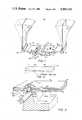
- FIG. 1is an axonometric view of a non-vibrational oscillating blade piezoelectric blower according to this invention with transverse end mounted blades;
- FIG. 2is a schematic axonometric view showing the inertial node pair in an unconstrained piezoelectric bender
- FIG. 3is an enlarged sectional view of a portion of the non-vibrational oscillating blade piezoelectric blower of FIG. 1;
- FIG. 4is an axonometric view of another construction of a non-vibrational oscillating blade piezoelectric blower according to this invention with a parallel, centrally mounted blade;
- FIG. 5is an axonometric view of yet another non-vibrational oscillating blade piezoelectric blower according to this invention with end nodes, a parallel mounted blade, and a second counter-oscillating bender;
- FIG. 6is an axonometric view of yet another non-vibrational oscillating blade piezoelectric blower according to this invention with a folded bender and split blade construction;
- FIG. 7is a schematic diagram of a driver circuit for driving the benders according to this invention.
- FIG. 1a non-vibrational oscillating blade piezoelectric blower 10 according to this invention, including a piezoelectric bender 12 mounted at its inertial nodal pair points or lines 14 and 16 on mounting members 18 and 20 of yoke 22 which is fixed to a circuit board or housing.
- the location of the inertial nodal pair 14a, 16a, FIG. 2may be determined by standard experimental procedures, for instance by driving the entire assembly consisting of bender, blades and weights into oscillation at low amplitude with minimal support and observing the motion under stroboscopic light.
- At the outer ends 24, 26, FIG. 1, of bender 12there are mounted flexible blades 28 and 30, disposed normal to bender 12 and secured thereto by some means such as an adhesive or interconnection blocks 32, 34. Blades 28, 30 are parallel to one another and counter-oscillate simultaneously toward and away from each other so that any transverse vibration cancels, resulting in virtually vibration-free operation in the transverse and longitudinal directions.
- a balance weight 36may be disposed between inertial nodes 14 and 16 to bring the inertial nodes closer to each other and to adjust the resonant frequency of the blower as desired.
- Members 18 and 20may have a curved top portion 38 and 40 to provide a line contact support 42, 44 to coincide with the node lines 14 and 16.
- Bender 12may be fastened to members 18 and 20 by means of screws 46, 48 which pass through clearance holes 50 in bender 12 and engage in threaded holes 52, FIG. 3, in members 18 and 20.
- Steel springs 54 and 56mounted beneath the heads of screws 46 and 48 resiliently secure bender 12 against support members 18 and 20 of yoke 22. As illustrated with respect to member 18, the rounded portion 38, FIG.
- Bender 12is formed of a plurality of piezoelectric layers, including at least two piezoelectric layers 70, 72, separated by an elastic conducting member 74 and bear on their external surfaces electrode material 76, 78. Electrical connection may be made to electrode 76 through wire 80 which engages screw 46 and spring 54. Electrical connection to electrode 78 may be made through wire 82, FIG. 1, which interconnects with a solder lug 84 attached to steel rod 60.
- blades 28 and 30may be formed of material such as Mylar polyester having the dimensions 5 to 14 mils thick, one inch wide, with the length adjusted to resonate at the desired frequency and with a high Q as described in pending application Ser. No. 477,630.
- Bender 12is typically 1.5 inches long 0.75 inch wide, .022 inch thick, and is formed of piezoelectric layes 70 and 72 of lead zirconate titanate piezoceramic material, 0.008 inch thick.
- Center shim 74is brass or steel, 0.004 inch thick, and electrodes 76, 78 are nickel or silver plating, 0.0001 inch thick.
- Balance weight 36is two grams, as determined by experiment.
- Screws 46, 48are made of insulating material and springs 54, 56 are formed of an elastic material having very low internal damping such as brass, phosphor bronze, or beryllium bronze.
- the inertial nodal pairoccur centered on bender 12 and spaced apart a distance of about one inch.
- blower 10bin another construction, blower 10b, FIG. 4, includes a piezoelectric bender 12b mounted at its inertial nodes 14b, 16b, by mounting members 18b and 20b of yoke 22b. At the outer ends 24b, 26b of bender 12b are secured balance weights 36b and 36bb. Blade 28b is centrally connected to bender 12b between nodes 14 and 16 by means of an interconnection element 90 connected to lateral edge 91 of bender 12b, which serves to stiffen blade 28b. Blade 28b may be provided with slots 92, 94 which divide it into three portions 96, 98 and 100. This separation of blade 28b into three parts provides a quieter blowing action.
- a second blade 28bbmay be provided on the opposite lateral edge 93 of bender 12b. Blades 28b and 28bb are generally parallel to bender 12.
- Blower 10b of FIG. 4is particularly suited to miniature low-profile applications and is suitable for use as a spot cooler mounted directly on a printed circuit board. It can be fabricated to have a total height of less than one half inch above the mounting surface. Miniature blowers of this type perform best at a frequency of about 400 Hz, but it may be expedient to operate them at about 200 Hz in order to minimize the acoustic noise. The blower can be operated at a voltage as low as 12 volts d.c.
- Blower l2bcan deliver air velocity of 400 ft./minute, and with a second blade it can be made to blow in opposite directions simultaneously.
- blower 10cmay be constructed using two counteroscillating benders 12c and 12cc whose combined nodes 14c, 14cc and 16c, 16cc are at their ends connected to upstanding members 18c, 20c of yoke 22c.
- Blade 28cmay be connected centrally of bender 12c by bracket 90c as explained with reference to FIG. 4, and a second blade on the opposite lateral edge 103c may be mounted in the same way if desired. Both blades 28c and 28cc may be generally parallel to bender 12c.
- Bender 12cis driven to oscillate simultaneously oppositely to bender 12c.
- the counter-oscillation mode of bender 12cccancels complementary vibrations of bender 12c.
- blower 10dFIG. 6, which includes a folded bender 12d mounted at its nodal points 14d, 16d on members 18d, 20d of yoke 22d (points 14d and 18d not visible).
- Folded bender 12dincludes primary bender 112 mounted at its nodes 14d and 16d on members 18d, 20d of yoke 22d.
- Folded bender 12dalso includes two extender bender sections 114 and 116 which are connected at their outer ends with the ends of bender 112 by means of interconnection blocks 118 and 120.
- Benders 114 and 116extend inwardly spaced from and parallel to bender 112, and at their inner ends support blades 28d and 28dd supported by brackets 90d and 90dd.
- the bender 112 and benders 114 and 116counter-oscillate so that the outer extremities of bender 112 and the three inner extremities of benders 114 and 116 all move upward and downward, respectively, in unison. This results in the maximum possible amplitude of the three inner extremities of the upper benders.
- This constructionis also particularly suitable for miniature low-profile applications, especially where operation at the lowest possible voltage direct current is required.
- a self-tuning circuit 130which includes two converting amplifiers 132, 134 in series driving outer electrodes 136 and 138 interconnected by line 140.
- piezoelectric bender 142is driven at resonance.
- Center electrode 144made of shimstock, is connected to the input of amplifier 13 via line 146.
- Feedback electrode 148is connected to the output of inverter 134 through capacitor 150 and to the inputs of amplifiers 132, 134 through feedback resistors 152, 154, respectively.
Landscapes
- Engineering & Computer Science (AREA)
- Mechanical Engineering (AREA)
- General Engineering & Computer Science (AREA)
- Structures Of Non-Positive Displacement Pumps (AREA)
Abstract
Description
This invention relates to a non-vibrational oscillating blade piezoelectric blower.
Piezoelectric fans or blowers are available which use a piezoelectric bender attached at one end to a housing. A flexible blade is attached near or at the other, free end of the piezoelectric bender. When an alternating voltage is applied to the piezoelectric bender, the free end drives the flexible blade into oscillation and moves air or other fluid by generation and shedding of vortices from the tip of the blade, U.S. patent application, Ser. No. 477,630 filed Mar. 22, 1983, now U.S. Pat. No. 4,498,851. Such a device transmits vibrations to the housing. To reduce this vibration, the blowers are usually constructed with pairs of counter-oscillating piezoelectric benders and blades. This ordinarily eliminates vibration in the transverse mode due to the cancellation of momentum from the counter-oscillating benders and blades. However, since the blades perform arcuate oscillation, there are also momentum oscillations in the longitudinal direction which are not cancelled by the counter-oscillation in the transverse dimension. There results a longitudinal vibration of the housing, which can be absorbed if the blower is of substantially less mass than the housing, or if suitable damping can be provided. For larger blowers and where vibration causes problems, the longitudinal vibrations can be unacceptable. Employing a cancellation approach is not appropriate for a second counter-oscillating unit 180° out of phase with the main unit, for unless the second unit could be designed to do useful work it would double the cost, mass, volume and components of the system without adding to its performance.
It is, therefore, an object of this invention to provide an improved, simple and efficient non-vibrational oscillating blade piezoelectric blower.
It is a further object of this invention to provide such a blower which virtually eliminates longitudinal as well as transverse vibration.
It is a further object of this invention to provide such a blower which eliminates longitudinal vibration without the use of counter-oscillating compensating units.
It is a further object of this invention to provide such a blower using inertial nodal support of the piezoelectric bender.
The invention results from the realization that in an unconstrained piezoelectric bender undergoing flexural oscillation, there are two nodes which remain stationary and that a bender supported at only these nodes introduces virtually no longitudinal vibration. Blades can be attached to this bender at or near anti-nodes in various positions and orientations in order to perform blowing action. Such blades will shift the position of the inertial nodes. It is also possible to shift the position of the inertial nodes by attaching weights to the bender.
This invention features a non-vibrational oscillating blade piezoelectric blower, including a piezoelectric bender and means for supporting the piezoelectric bender at its inertial nodes. A flexible blade is mounted to the piezoelectric bender remote from the nodes and driven to oscillate by the piezoelectric bender. In one construction, the blade is mounted to the bender between the nodes and is generally parallel to the bender. The blade is mounted to one lateral edge of the bender and the second blade may be mounted to the opposite lateral edge of the bender. There may be a balancing weight mounted to the bender beyond each node, and the means for supporting may include an elastic mounting means for securing the piezoelectric bender.
In another construction, the inertial nodes may be disposed at the ends of the bender and the means for supporting may support the bender at its ends. Further, there may be a second bender having inertial nodes at its ends and also mounted to the means for supporting parallel to the first bender. The blade or blades may be mounted to the bender by a connecting bracket which stiffens the bender, and the blade or blades may be divided into a plurality of sections with a common base.
In another construction, the bender may extend beyond the nodes and a blade may be attached to the bender beyond each said node, and each blade may be mounted transversely to the bender.
In yet another construction, the bender is folded and includes first and second extended bender sections, each attached to one end of the bender and extending inwardly along, spaced from and parallel to the bender. The blade may include two separate blade portions, one attached to each of the adjacent inner ends of the bender sections. The bender may include a balancing weight mounted to it between the nodes. The elastic mounting means may have low internal damping and there may be a drive circuit for oscillating the bender.
Other objects, features and advantages will occur from the following description of a preferred embodiment and the accompanying drawings, in which:
FIG. 1 is an axonometric view of a non-vibrational oscillating blade piezoelectric blower according to this invention with transverse end mounted blades;
FIG. 2 is a schematic axonometric view showing the inertial node pair in an unconstrained piezoelectric bender;
FIG. 3 is an enlarged sectional view of a portion of the non-vibrational oscillating blade piezoelectric blower of FIG. 1;
FIG. 4 is an axonometric view of another construction of a non-vibrational oscillating blade piezoelectric blower according to this invention with a parallel, centrally mounted blade;
FIG. 5 is an axonometric view of yet another non-vibrational oscillating blade piezoelectric blower according to this invention with end nodes, a parallel mounted blade, and a second counter-oscillating bender;
FIG. 6 is an axonometric view of yet another non-vibrational oscillating blade piezoelectric blower according to this invention with a folded bender and split blade construction; and
FIG. 7 is a schematic diagram of a driver circuit for driving the benders according to this invention.
There is shown in FIG. 1 a non-vibrational oscillating bladepiezoelectric blower 10 according to this invention, including apiezoelectric bender 12 mounted at its inertial nodal pair points orlines members yoke 22 which is fixed to a circuit board or housing.
In every body which undergoes flexural oscillation, there is a locus of points that remain fixed if the body is made to oscillate while free of any external force. This is a corrollary of the law of conservation of momentum. This is case of a linear flexural element such as a long narrowpiezoelectric bender 12a, FIG. 2, the locus consists of two stationary points orlines bender 12a oscillates as shown, the conservation of momentum requires that these twonodes members yoke 22, FIG. 1, as the bender oscillates.
The location of theinertial nodal pair outer ends bender 12, there are mountedflexible blades bender 12 and secured thereto by some means such as an adhesive orinterconnection blocks Blades
Abalance weight 36, FIG. 1, may be disposed betweeninertial nodes Members top portion line contact support node lines members screws clearance holes 50 inbender 12 and engage in threadedholes 52, FIG. 3, inmembers Steel springs screws secure bender 12 againstsupport members yoke 22. As illustrated with respect tomember 18, therounded portion 38, FIG. 3, may be formed by acircular steel rod 60 inserted inbore 62. Itsupper area 64 is open so that the top,curved surface 66 ofrod 60 actually provides theline 42 of contact withbender 12. The steel rod support can also be replaced by a resilient support, such as a second steel spring underneath the bender. Bender 12 is formed of a plurality of piezoelectric layers, including at least twopiezoelectric layers member 74 and bear on their externalsurfaces electrode material 76, 78. Electrical connection may be made to electrode 76 throughwire 80 which engagesscrew 46 andspring 54. Electrical connection to electrode 78 may be made through wire 82, FIG. 1, which interconnects with asolder lug 84 attached tosteel rod 60.
In a specific embodiment,blades Bender 12 is typically 1.5 inches long 0.75 inch wide, .022 inch thick, and is formed ofpiezoelectric layes Center shim 74 is brass or steel, 0.004 inch thick, andelectrodes 76, 78 are nickel or silver plating, 0.0001 inch thick.Balance weight 36 is two grams, as determined by experiment.Screws bender 12 and spaced apart a distance of about one inch.
In another construction, blower 10b, FIG. 4, includes apiezoelectric bender 12b mounted at itsinertial nodes members yoke 22b. At the outer ends 24b, 26b ofbender 12b are securedbalance weights 36b and 36bb.Blade 28b is centrally connected tobender 12b betweennodes interconnection element 90 connected tolateral edge 91 ofbender 12b, which serves to stiffenblade 28b.Blade 28b may be provided withslots portions blade 28b into three parts provides a quieter blowing action. A second blade 28bb may be provided on the opposite lateral edge 93 ofbender 12b.Blades 28b and 28bb are generally parallel tobender 12. Blower 10b of FIG. 4 is particularly suited to miniature low-profile applications and is suitable for use as a spot cooler mounted directly on a printed circuit board. It can be fabricated to have a total height of less than one half inch above the mounting surface. Miniature blowers of this type perform best at a frequency of about 400 Hz, but it may be expedient to operate them at about 200 Hz in order to minimize the acoustic noise. The blower can be operated at a voltage as low as 12 volts d.c. and driven by a self-tuning electronic circuit which is supplied with direct current and generates an alternating voltage automatically adjusted to the resonant frequency of the bender of the attached blade and weights, as shown in FIG. 7. The weights on the outer ends ofbender 12b move the inertial nodes outward and increase the amplitude of oscillation at the center of the bender. Blower l2b can deliver air velocity of 400 ft./minute, and with a second blade it can be made to blow in opposite directions simultaneously.
Alternatively, blower 10c, FIG. 5, may be constructed using twocounteroscillating benders 12c and 12cc whose combinednodes 14c, 14cc and 16c, 16cc are at their ends connected toupstanding members 18c, 20c ofyoke 22c.Blade 28c may be connected centrally ofbender 12c bybracket 90c as explained with reference to FIG. 4, and a second blade on the oppositelateral edge 103c may be mounted in the same way if desired. Bothblades 28c and 28cc may be generally parallel tobender 12c.Bender 12c is driven to oscillate simultaneously oppositely tobender 12c. The counter-oscillation mode of bender 12cc cancels complementary vibrations ofbender 12c.
Increased deflection may be obtained fromblower 10d, FIG. 6, which includes a foldedbender 12d mounted at itsnodal points 14d, 16d onmembers 18d, 20d ofyoke 22d (points 14d and 18d not visible). Foldedbender 12d includesprimary bender 112 mounted at itsnodes 14d and 16d onmembers 18d, 20d ofyoke 22d. Foldedbender 12d also includes twoextender bender sections 114 and 116 which are connected at their outer ends with the ends ofbender 112 by means of interconnection blocks 118 and 120.Benders 114 and 116 extend inwardly spaced from and parallel tobender 112, and at their inner ends supportblades 28d and 28dd supported bybrackets 90d and 90dd. Thebender 112 andbenders 114 and 116 counter-oscillate so that the outer extremities ofbender 112 and the three inner extremities ofbenders 114 and 116 all move upward and downward, respectively, in unison. This results in the maximum possible amplitude of the three inner extremities of the upper benders. This construction is also particularly suitable for miniature low-profile applications, especially where operation at the lowest possible voltage direct current is required.
Acceptable performance has been achieved at a resonant driving voltage using a self-tuningcircuit 130, FIG. 7, which includes two convertingamplifiers outer electrodes line 140. Throughcircuit 130,piezoelectric bender 142 is driven at resonance.Center electrode 144, made of shimstock, is connected to the input of amplifier 13 vialine 146.Feedback electrode 148 is connected to the output ofinverter 134 throughcapacitor 150 and to the inputs ofamplifiers feedback resistors
Other embodiments will occur to those skilled in the art and are within the following claims:
Claims (22)
1. A non-vibrational oscillating blade piezoelectric blower comprising: a piezelectric bender having at least two spaced inertial nodes; means for supporting said piezoelelctric bender at each of said inertial nodes; and a flexible blade mounted to said piezoelectric bender remote from said nodes and driven to oscillate by said piezoelectric bender.
2. The blower of claim 1 in which said blade is mounted to said bender between said nodes.
3. The blower of claim 1 in which said blade is generally parallel to said bender.
4. The blower of claim 3 in which said blade is mounted to one lateral edge of said bender and a second blade is mounted to the opposite lateral edge of said bender.
5. The blower of claim 1 further including a balancing weight mounted to said bender beyond each said node.
6. The blower of claim 1 in which said means for supporting includes elastic mounting means for securing said piezoelectric bender.
7. The blower of claim 1 in which the inertial nodes are at the ends of said bender and said means for supporting support said bender at its ends.
8. The blower of claim 7 further including a second bender having inertial nodes at its ends and mounted to said means for supporting parallel to the first said bender.
9. The blower of claim 1 in which said blade is mounted to said bender by a connecting bracket which stiffens said blade.
10. The blower of claim 1 in which said blade is divided into a plurality of sections with a common base.
11. The blower of claim 1 in which said bender extends beyond said nodes and there is a blade attached to said bender beyond each said node.
12. The blower of claim 11 in which said blades are attached transversely of said bender.
13. The blower of claim 11 in which said bender is folded and includes first and second extended bender sections each attached to one end of said bender and extending inwardly along, spaced from, and parallel to said bender.
14. The blower of claim 13 in which said blade includes two separate blade portions one attached to each of the adjacent inner ends of said bender sections.
15. The blower of claim 1 in which said bender includes a balancing weight mounted to said bender between said nodes.
16. The blower of claim 1 in which said means for supporting have low internal damping.
17. The blower of claim 1 further including a drive circuit for oscillating said bender at resonance.
18. A non-vibrational oscillating blade piezoelectric blower comprising: a piezoelectric bender having at least two spaced inertial nodes; means for supporting said piezoelectric bender at its inertial nodes; and at least one flexible blade mounted parallel to and along a lateral edge of said piezoelectric bender between said nodes and driven to oscillate by said piezoelectric bender.
19. The blower of claim 18 in which said bender includes a balancing weight beyond each node.
20. A non-vibrational oscillating blade piezoelectric blower comprising: a piezoelectric bender having an inertial node at each end; means for supporting said piezoelectric bender at its inertial nodes; and at least one flexible blade mounted parallel to and along a lateral edge of said piezoelectric bender between said nodes and driven to oscillate by said piezoelectric bender.
21. The blower of claim 20 further including a second bender having inertial nodes at its ends and mounted to said means for supporting parallel to the first said bender.
22. A non-vibrational oscillating blade piezoelectric blower comprising: a folded piezoelectric bender having at least two spaced inertial nodes and including first and second extended bender sections each attached to one end of said bender and extending inwardly along, spaced from and parallel to said bender; means for supporting said piezoelectric bender at its inertial nodes; a flexible blade including two separate blade portions one attached to each of the adjacent inner ends of said bender sections and driven to oscillate by said piezoelectric bender.
Priority Applications (5)
| Application Number | Priority Date | Filing Date | Title |
|---|---|---|---|
| US06/552,972US4595338A (en) | 1983-11-17 | 1983-11-17 | Non-vibrational oscillating blade piezoelectric blower |
| PCT/US1984/001270WO1985002231A1 (en) | 1983-11-17 | 1984-08-13 | Non-vibrating oscillating blade piezoelectric blower |
| EP84903147AEP0162051A1 (en) | 1983-11-17 | 1984-08-13 | Non-vibrating oscillating blade piezoelectric blower |
| JP59503125AJPS61500865A (en) | 1983-11-17 | 1984-08-13 | Piezoelectric element blower that prevents vibration transmission |
| IT8422807AIT8422807A0 (en) | 1983-11-17 | 1984-09-24 | PIEZOELECTRIC FAN WITH OSCILLATING BLADES WITHOUT VIBRATIONS. |
Applications Claiming Priority (1)
| Application Number | Priority Date | Filing Date | Title |
|---|---|---|---|
| US06/552,972US4595338A (en) | 1983-11-17 | 1983-11-17 | Non-vibrational oscillating blade piezoelectric blower |
Publications (1)
| Publication Number | Publication Date |
|---|---|
| US4595338Atrue US4595338A (en) | 1986-06-17 |
Family
ID=24207591
Family Applications (1)
| Application Number | Title | Priority Date | Filing Date |
|---|---|---|---|
| US06/552,972Expired - Fee RelatedUS4595338A (en) | 1983-11-17 | 1983-11-17 | Non-vibrational oscillating blade piezoelectric blower |
Country Status (5)
| Country | Link |
|---|---|
| US (1) | US4595338A (en) |
| EP (1) | EP0162051A1 (en) |
| JP (1) | JPS61500865A (en) |
| IT (1) | IT8422807A0 (en) |
| WO (1) | WO1985002231A1 (en) |
Cited By (80)
| Publication number | Priority date | Publication date | Assignee | Title |
|---|---|---|---|---|
| US4708600A (en)* | 1986-02-24 | 1987-11-24 | Abujudom Ii David N | Piezoelectric fluid pumping apparatus |
| US4755105A (en)* | 1986-10-27 | 1988-07-05 | Chemcut Corporation | Impeller improvement |
| US4834619A (en)* | 1987-11-10 | 1989-05-30 | The Boeing Company | Ducted oscillatory blade fan |
| US5008582A (en)* | 1988-01-29 | 1991-04-16 | Kabushiki Kaisha Toshiba | Electronic device having a cooling element |
| US5151626A (en)* | 1986-11-04 | 1992-09-29 | Hughes Aircraft Company | Repetitive pulsed Raman cell with vibrating blade |
| US5406531A (en)* | 1993-04-30 | 1995-04-11 | The United States Of America As Represented By The Secretary Of The Navy | Low frequency flex-beam underwater acoustic transducer |
| US5522712A (en)* | 1993-12-08 | 1996-06-04 | Winn; Ray | Low-powered cooling fan for dissipating heat |
| US5558156A (en)* | 1994-01-21 | 1996-09-24 | Honda Giken Kogyo Kabushiki | Heat exchanger |
| WO1997046067A1 (en)* | 1996-05-31 | 1997-12-04 | Intel Corporation | Cooling system for thin profile computer electronics |
| US5861703A (en)* | 1997-05-30 | 1999-01-19 | Motorola Inc. | Low-profile axial-flow single-blade piezoelectric fan |
| US5983944A (en)* | 1998-03-20 | 1999-11-16 | Niv; Shaul E. | Apparatus for active fluid control |
| US6013972A (en)* | 1997-10-15 | 2000-01-11 | Face, Jr.; Samuel A | Piezoelectric vibrating apparatus |
| US6222302B1 (en)* | 1997-09-30 | 2001-04-24 | Matsushita Electric Industrial Co., Ltd. | Piezoelectric actuator, infrared sensor and piezoelectric light deflector |
| US6323583B1 (en)* | 1998-04-24 | 2001-11-27 | Siemens Aktiengesellschaft | Piezoelectric transducer for incorporation into a module |
| US6332756B1 (en)* | 1999-01-12 | 2001-12-25 | Yugen Kaisha Sozoan | Motion converting unit |
| US6612816B1 (en)* | 1998-10-20 | 2003-09-02 | Pierre Vanden Brande | Molecular pump |
| US6713942B2 (en)* | 2001-05-23 | 2004-03-30 | Purdue Research Foundation | Piezoelectric device with feedback sensor |
| US20040190305A1 (en)* | 2003-03-31 | 2004-09-30 | General Electric Company | LED light with active cooling |
| US20040207292A1 (en)* | 2002-02-15 | 2004-10-21 | Scher Irving S | Small piezoelectric air pumps with unobstructed airflow |
| US20040253130A1 (en)* | 2003-01-06 | 2004-12-16 | Ioan Sauciuc | Electronic thermal management |
| US20050258713A1 (en)* | 2002-07-31 | 2005-11-24 | Siemens Aktiengesellschaft | Piezoactuator and method for production of the piezoactuator |
| US20060158065A1 (en)* | 1999-07-20 | 2006-07-20 | Sri International A California Corporation | Electroactive polymer devices for moving fluid |
| US20060185822A1 (en)* | 2004-07-07 | 2006-08-24 | Georgia Tech Research Corporation | System and method for thermal management using distributed synthetic jet actuators |
| US20070001550A1 (en)* | 2005-06-30 | 2007-01-04 | Palanduz Cengiz A | Piezo actuator for cooling |
| US20070023169A1 (en)* | 2005-07-29 | 2007-02-01 | Innovative Fluidics, Inc. | Synthetic jet ejector for augmentation of pumped liquid loop cooling and enhancement of pool and flow boiling |
| US20070037506A1 (en)* | 2005-08-09 | 2007-02-15 | Seri Lee | Rake shaped fan |
| US20070096118A1 (en)* | 2005-11-02 | 2007-05-03 | Innovative Fluidics, Inc. | Synthetic jet cooling system for LED module |
| US20070119575A1 (en)* | 2005-11-14 | 2007-05-31 | Innovative Fluidics, Inc. | Synthetic jet heat pipe thermal management system |
| US20070139938A1 (en)* | 2003-03-31 | 2007-06-21 | Lumination, Llc | Led light with active cooling |
| US20070147046A1 (en)* | 2003-03-31 | 2007-06-28 | Lumination, Llc | Led light with active cooling |
| US20080218968A1 (en)* | 2007-03-08 | 2008-09-11 | Anandaroop Bhattacharya | Winged piezo fan |
| US20080238256A1 (en)* | 2007-03-30 | 2008-10-02 | Javier Leija | Dual direction rake piezo actuator |
| US20090004034A1 (en)* | 2007-06-29 | 2009-01-01 | Seri Lee | Piezoelectric fan |
| US20100038994A1 (en)* | 2006-10-04 | 2010-02-18 | Bernhard Eichhorner | Switched mode power supply |
| US20100314967A1 (en)* | 2009-06-11 | 2010-12-16 | Samsung Electronics Co., Ltd. | Surface acoustic wave sensor device |
| US20110014069A1 (en)* | 2008-03-25 | 2011-01-20 | Murata Manufacturing Co., Ltd. | Piezoelectric fan device and air-cooling apparatus using the piezoelectric fan device |
| US20110063800A1 (en)* | 2009-09-14 | 2011-03-17 | Kwan Woo Park | Heat dissipating device |
| US20110070109A1 (en)* | 2008-06-05 | 2011-03-24 | Murata Manufacturing Co., Ltd. | Piezoelectric microblower |
| US20110122582A1 (en)* | 2009-11-20 | 2011-05-26 | Kwan Woo Park | Heat dissipating device |
| US8030886B2 (en) | 2005-12-21 | 2011-10-04 | Nuventix, Inc. | Thermal management of batteries using synthetic jets |
| US8322889B2 (en) | 2006-09-12 | 2012-12-04 | GE Lighting Solutions, LLC | Piezofan and heat sink system for enhanced heat transfer |
| DE102012200925A1 (en)* | 2012-01-23 | 2013-07-25 | Siemens Aktiengesellschaft | Electric power transmission device with a movable blade and method for moving a sheet |
| US20140166260A1 (en)* | 2012-12-13 | 2014-06-19 | Goodrich Lighting Systems Gmbh | Method for controlling a mechanical vibrating element |
| US20140168894A1 (en)* | 2012-01-25 | 2014-06-19 | Toyota Motor Engineering & Manufacturing North America, Inc. | Cooling Apparatuses, Electronic Device Assemblies, and Cooling Assemblies Using Magnetic Shape Memory Members |
| US20140216696A1 (en)* | 2013-02-01 | 2014-08-07 | Alcatel Lucent | Cooling device and a cooling assembly comprising the cooling device |
| US20150023819A1 (en)* | 2012-04-17 | 2015-01-22 | Murata Manufacturing Co., Ltd. | Piezoelectric fan |
| US9195058B2 (en) | 2011-03-22 | 2015-11-24 | Parker-Hannifin Corporation | Electroactive polymer actuator lenticular system |
| US9231186B2 (en) | 2009-04-11 | 2016-01-05 | Parker-Hannifin Corporation | Electro-switchable polymer film assembly and use thereof |
| CN105376989A (en)* | 2014-08-29 | 2016-03-02 | 台达电子工业股份有限公司 | heat sink |
| US9425383B2 (en) | 2007-06-29 | 2016-08-23 | Parker-Hannifin Corporation | Method of manufacturing electroactive polymer transducers for sensory feedback applications |
| US9553254B2 (en) | 2011-03-01 | 2017-01-24 | Parker-Hannifin Corporation | Automated manufacturing processes for producing deformable polymer devices and films |
| EP2609338A4 (en)* | 2010-08-25 | 2017-02-15 | Aavid Thermalloy, LLC | Cantilever fan |
| US9590193B2 (en) | 2012-10-24 | 2017-03-07 | Parker-Hannifin Corporation | Polymer diode |
| CN106662122A (en)* | 2014-08-25 | 2017-05-10 | 通用电气航空系统有限责任公司 | Airflow generator and array of airflow generators |
| US20170181316A1 (en)* | 2015-12-18 | 2017-06-22 | Hsien-Chin SU | Heat dissipating device and swing structure thereof |
| US9761790B2 (en) | 2012-06-18 | 2017-09-12 | Parker-Hannifin Corporation | Stretch frame for stretching process |
| US9856868B2 (en)* | 2012-02-13 | 2018-01-02 | Murata Manufacturing Co., Ltd. | Piezoelectric fan |
| US9876160B2 (en) | 2012-03-21 | 2018-01-23 | Parker-Hannifin Corporation | Roll-to-roll manufacturing processes for producing self-healing electroactive polymer devices |
| US10184493B2 (en)* | 2016-03-04 | 2019-01-22 | Tung Thanh NGUYEN | Piezo flapping fan |
| CN112392780A (en)* | 2020-10-09 | 2021-02-23 | 杨杰 | Piezoelectric fan structure capable of blowing air to periphery and driving method |
| US11432433B2 (en)* | 2019-12-06 | 2022-08-30 | Frore Systems Inc. | Centrally anchored MEMS-based active cooling systems |
| US11456234B2 (en) | 2018-08-10 | 2022-09-27 | Frore Systems Inc. | Chamber architecture for cooling devices |
| US11503742B2 (en) | 2019-12-06 | 2022-11-15 | Frore Systems Inc. | Engineered actuators usable in MEMS active cooling devices |
| US20230011084A1 (en)* | 2021-07-12 | 2023-01-12 | Frore Systems Inc. | Cooling element architecture for mems-based cooling system architecture |
| US20230049263A1 (en)* | 2020-03-04 | 2023-02-16 | Perpetua, Inc. | Linear fan forced air cooling |
| CN116357628A (en)* | 2021-12-28 | 2023-06-30 | 乐金显示有限公司 | Blowing device |
| US11765863B2 (en) | 2020-10-02 | 2023-09-19 | Frore Systems Inc. | Active heat sink |
| US11796262B2 (en) | 2019-12-06 | 2023-10-24 | Frore Systems Inc. | Top chamber cavities for center-pinned actuators |
| US11802554B2 (en) | 2019-10-30 | 2023-10-31 | Frore Systems Inc. | MEMS-based airflow system having a vibrating fan element arrangement |
| US20230349396A1 (en)* | 2019-12-04 | 2023-11-02 | Perpetua, Inc. | Linear fan including wire springs |
| US12029005B2 (en) | 2019-12-17 | 2024-07-02 | Frore Systems Inc. | MEMS-based cooling systems for closed and open devices |
| US12033917B2 (en) | 2019-12-17 | 2024-07-09 | Frore Systems Inc. | Airflow control in active cooling systems |
| US12089374B2 (en) | 2018-08-10 | 2024-09-10 | Frore Systems Inc. | MEMS-based active cooling systems |
| US12152570B2 (en) | 2023-02-22 | 2024-11-26 | Toyota Motor Engineering & Manufacturing North America, Inc. | Shape memory material member-based actuator with electrostatic clutch preliminary class |
| US12163507B2 (en) | 2023-02-22 | 2024-12-10 | Toyota Motor Engineering & Manufacturing North America, Inc. | Contracting member-based actuator with clutch |
| US12193192B2 (en) | 2019-12-06 | 2025-01-07 | Frore Systems Inc. | Cavities for center-pinned actuator cooling systems |
| US12234811B1 (en) | 2023-08-21 | 2025-02-25 | Toyota Motor Engineering & Manufacturing North America, Inc. | Monitoring a state of a shape memory material member |
| US12241458B2 (en) | 2023-02-16 | 2025-03-04 | Toyota Motor Engineering & Manufacturing North America, Inc. | Actuator with contracting member |
| US12270386B2 (en) | 2023-02-16 | 2025-04-08 | Toyota Motor Engineering & Manufacturing North America, Inc. | Shape memory material member-based actuator |
| US12383066B2 (en) | 2022-04-26 | 2025-08-12 | Toyota Motor Engineering & Manufacturing North America, Inc. | Chair with shape memory material-based movement synchronized with visual content |
Families Citing this family (2)
| Publication number | Priority date | Publication date | Assignee | Title |
|---|---|---|---|---|
| JPH0219700A (en)* | 1988-07-07 | 1990-01-23 | Matsushita Electric Ind Co Ltd | piezoelectric fan |
| DE19910731A1 (en)* | 1999-03-11 | 2000-09-14 | Robert Spillner | Method and device for a turbomachine with reciprocating parts |
Citations (11)
| Publication number | Priority date | Publication date | Assignee | Title |
|---|---|---|---|---|
| US1486040A (en)* | 1921-08-24 | 1924-03-04 | Schieferstein Georg Heinrich | Tuned mechanically-oscillating system |
| AT167983B (en)* | 1949-05-28 | 1951-03-27 | Josef Anderle | Pump for liquid or gaseous working media |
| US3040976A (en)* | 1959-08-17 | 1962-06-26 | Mattos Jorge J De | Air propelling means |
| US3206986A (en)* | 1963-01-04 | 1965-09-21 | Western Electric Co | Apparatus for sensing selected movements of a body |
| US3620651A (en)* | 1969-02-07 | 1971-11-16 | Int Combustion Holdings Ltd | Fluid flow apparatus |
| US3821747A (en)* | 1973-04-23 | 1974-06-28 | Atomic Energy Commission | Recording system having piezoelectric stylus drive means |
| US4063826A (en)* | 1975-05-20 | 1977-12-20 | Waldemar Riepe | Flexible, oscillating blade liquid pump |
| US4131874A (en)* | 1977-05-12 | 1978-12-26 | Westinghouse Electric Corp. | Inertial balanced dipole hydrophone |
| US4172427A (en)* | 1978-01-12 | 1979-10-30 | Kindred William B | Water propulsion unit including fin having foil and flexible ends |
| US4176976A (en)* | 1977-04-15 | 1979-12-04 | Triumph Werke Nurnberg A.G. | Mosaic printing head |
| WO1980002445A1 (en)* | 1979-05-07 | 1980-11-13 | Rotron Inc | Solid state blower |
Family Cites Families (2)
| Publication number | Priority date | Publication date | Assignee | Title |
|---|---|---|---|---|
| JPS54164008A (en)* | 1977-05-26 | 1979-12-27 | Rca Corp | Fan employing high polymer piezobimorph element |
| JPS60162100A (en)* | 1984-02-02 | 1985-08-23 | Nippon Denso Co Ltd | Piezo-electric fan apparatus |
- 1983
- 1983-11-17USUS06/552,972patent/US4595338A/ennot_activeExpired - Fee Related
- 1984
- 1984-08-13JPJP59503125Apatent/JPS61500865A/enactivePending
- 1984-08-13WOPCT/US1984/001270patent/WO1985002231A1/enunknown
- 1984-08-13EPEP84903147Apatent/EP0162051A1/ennot_activeWithdrawn
- 1984-09-24ITIT8422807Apatent/IT8422807A0/enunknown
Patent Citations (11)
| Publication number | Priority date | Publication date | Assignee | Title |
|---|---|---|---|---|
| US1486040A (en)* | 1921-08-24 | 1924-03-04 | Schieferstein Georg Heinrich | Tuned mechanically-oscillating system |
| AT167983B (en)* | 1949-05-28 | 1951-03-27 | Josef Anderle | Pump for liquid or gaseous working media |
| US3040976A (en)* | 1959-08-17 | 1962-06-26 | Mattos Jorge J De | Air propelling means |
| US3206986A (en)* | 1963-01-04 | 1965-09-21 | Western Electric Co | Apparatus for sensing selected movements of a body |
| US3620651A (en)* | 1969-02-07 | 1971-11-16 | Int Combustion Holdings Ltd | Fluid flow apparatus |
| US3821747A (en)* | 1973-04-23 | 1974-06-28 | Atomic Energy Commission | Recording system having piezoelectric stylus drive means |
| US4063826A (en)* | 1975-05-20 | 1977-12-20 | Waldemar Riepe | Flexible, oscillating blade liquid pump |
| US4176976A (en)* | 1977-04-15 | 1979-12-04 | Triumph Werke Nurnberg A.G. | Mosaic printing head |
| US4131874A (en)* | 1977-05-12 | 1978-12-26 | Westinghouse Electric Corp. | Inertial balanced dipole hydrophone |
| US4172427A (en)* | 1978-01-12 | 1979-10-30 | Kindred William B | Water propulsion unit including fin having foil and flexible ends |
| WO1980002445A1 (en)* | 1979-05-07 | 1980-11-13 | Rotron Inc | Solid state blower |
Non-Patent Citations (2)
| Title |
|---|
| Toda et al., "Vibrational Fan Using the Piezoelectric Polymer PVF2", Proceedings of the IEEE, Aug. 1979, p. 1171. |
| Toda et al., Vibrational Fan Using the Piezoelectric Polymer PVF 2 , Proceedings of the IEEE, Aug. 1979, p. 1171.* |
Cited By (123)
| Publication number | Priority date | Publication date | Assignee | Title |
|---|---|---|---|---|
| US4708600A (en)* | 1986-02-24 | 1987-11-24 | Abujudom Ii David N | Piezoelectric fluid pumping apparatus |
| US4755105A (en)* | 1986-10-27 | 1988-07-05 | Chemcut Corporation | Impeller improvement |
| US5151626A (en)* | 1986-11-04 | 1992-09-29 | Hughes Aircraft Company | Repetitive pulsed Raman cell with vibrating blade |
| US4834619A (en)* | 1987-11-10 | 1989-05-30 | The Boeing Company | Ducted oscillatory blade fan |
| US5008582A (en)* | 1988-01-29 | 1991-04-16 | Kabushiki Kaisha Toshiba | Electronic device having a cooling element |
| US5406531A (en)* | 1993-04-30 | 1995-04-11 | The United States Of America As Represented By The Secretary Of The Navy | Low frequency flex-beam underwater acoustic transducer |
| US5522712A (en)* | 1993-12-08 | 1996-06-04 | Winn; Ray | Low-powered cooling fan for dissipating heat |
| US5558156A (en)* | 1994-01-21 | 1996-09-24 | Honda Giken Kogyo Kabushiki | Heat exchanger |
| WO1997046067A1 (en)* | 1996-05-31 | 1997-12-04 | Intel Corporation | Cooling system for thin profile computer electronics |
| US5966286A (en)* | 1996-05-31 | 1999-10-12 | Intel Corporation | Cooling system for thin profile electronic and computer devices |
| US5861703A (en)* | 1997-05-30 | 1999-01-19 | Motorola Inc. | Low-profile axial-flow single-blade piezoelectric fan |
| US6222302B1 (en)* | 1997-09-30 | 2001-04-24 | Matsushita Electric Industrial Co., Ltd. | Piezoelectric actuator, infrared sensor and piezoelectric light deflector |
| US6013972A (en)* | 1997-10-15 | 2000-01-11 | Face, Jr.; Samuel A | Piezoelectric vibrating apparatus |
| US5983944A (en)* | 1998-03-20 | 1999-11-16 | Niv; Shaul E. | Apparatus for active fluid control |
| US6323583B1 (en)* | 1998-04-24 | 2001-11-27 | Siemens Aktiengesellschaft | Piezoelectric transducer for incorporation into a module |
| US6612816B1 (en)* | 1998-10-20 | 2003-09-02 | Pierre Vanden Brande | Molecular pump |
| US6332756B1 (en)* | 1999-01-12 | 2001-12-25 | Yugen Kaisha Sozoan | Motion converting unit |
| US20060158065A1 (en)* | 1999-07-20 | 2006-07-20 | Sri International A California Corporation | Electroactive polymer devices for moving fluid |
| US7362032B2 (en)* | 1999-07-20 | 2008-04-22 | Sri International | Electroactive polymer devices for moving fluid |
| US6713942B2 (en)* | 2001-05-23 | 2004-03-30 | Purdue Research Foundation | Piezoelectric device with feedback sensor |
| US20060208613A1 (en)* | 2002-02-15 | 2006-09-21 | Siemens Technology-To-Business Center Llc | Small piezoelectric air pumps with unobstructed airflow |
| US7061161B2 (en) | 2002-02-15 | 2006-06-13 | Siemens Technology-To-Business Center Llc | Small piezoelectric air pumps with unobstructed airflow |
| US7358649B2 (en) | 2002-02-15 | 2008-04-15 | Siemens Technology-To-Business Center, Llc | Small piezoelectric air pumps with unobstructed airflow |
| US20060208614A1 (en)* | 2002-02-15 | 2006-09-21 | Siemens Technology-To-Business Center Llc | Small piezoelectric air pumps with unobstructed airflow |
| US20040207292A1 (en)* | 2002-02-15 | 2004-10-21 | Scher Irving S | Small piezoelectric air pumps with unobstructed airflow |
| US7282837B2 (en) | 2002-02-15 | 2007-10-16 | Siemens Technology-To-Business Center Llc | Small piezoelectric air pumps with unobstructed airflow |
| US7417359B2 (en) | 2002-02-15 | 2008-08-26 | Siemens Technology-To-Business Center, Llc | Small piezoelectric air pumps with unobstructed airflow |
| US20070182286A1 (en)* | 2002-02-15 | 2007-08-09 | Siemens Technology-To-Business Center Llc | Small piezoelectric air pumps with unobstructed airflow |
| US20050258713A1 (en)* | 2002-07-31 | 2005-11-24 | Siemens Aktiengesellschaft | Piezoactuator and method for production of the piezoactuator |
| US7309944B2 (en)* | 2002-07-31 | 2007-12-18 | Siemens Aktiengesellschaft | Piezoactuator and method for production of the piezoactuator |
| US7031155B2 (en)* | 2003-01-06 | 2006-04-18 | Intel Corporation | Electronic thermal management |
| US20040253130A1 (en)* | 2003-01-06 | 2004-12-16 | Ioan Sauciuc | Electronic thermal management |
| US7556406B2 (en) | 2003-03-31 | 2009-07-07 | Lumination Llc | Led light with active cooling |
| US7543961B2 (en) | 2003-03-31 | 2009-06-09 | Lumination Llc | LED light with active cooling |
| US20070139938A1 (en)* | 2003-03-31 | 2007-06-21 | Lumination, Llc | Led light with active cooling |
| US20070147046A1 (en)* | 2003-03-31 | 2007-06-28 | Lumination, Llc | Led light with active cooling |
| US7204615B2 (en)* | 2003-03-31 | 2007-04-17 | Lumination Llc | LED light with active cooling |
| US20040190305A1 (en)* | 2003-03-31 | 2004-09-30 | General Electric Company | LED light with active cooling |
| US20060185822A1 (en)* | 2004-07-07 | 2006-08-24 | Georgia Tech Research Corporation | System and method for thermal management using distributed synthetic jet actuators |
| US20070001550A1 (en)* | 2005-06-30 | 2007-01-04 | Palanduz Cengiz A | Piezo actuator for cooling |
| US7638928B2 (en)* | 2005-06-30 | 2009-12-29 | Intel Corporation | Piezo actuator for cooling |
| US20070023169A1 (en)* | 2005-07-29 | 2007-02-01 | Innovative Fluidics, Inc. | Synthetic jet ejector for augmentation of pumped liquid loop cooling and enhancement of pool and flow boiling |
| US7321184B2 (en)* | 2005-08-09 | 2008-01-22 | Intel Corporation | Rake shaped fan |
| US20070037506A1 (en)* | 2005-08-09 | 2007-02-15 | Seri Lee | Rake shaped fan |
| US7932535B2 (en) | 2005-11-02 | 2011-04-26 | Nuventix, Inc. | Synthetic jet cooling system for LED module |
| US20070096118A1 (en)* | 2005-11-02 | 2007-05-03 | Innovative Fluidics, Inc. | Synthetic jet cooling system for LED module |
| US20070119575A1 (en)* | 2005-11-14 | 2007-05-31 | Innovative Fluidics, Inc. | Synthetic jet heat pipe thermal management system |
| US7607470B2 (en) | 2005-11-14 | 2009-10-27 | Nuventix, Inc. | Synthetic jet heat pipe thermal management system |
| US8030886B2 (en) | 2005-12-21 | 2011-10-04 | Nuventix, Inc. | Thermal management of batteries using synthetic jets |
| US8322889B2 (en) | 2006-09-12 | 2012-12-04 | GE Lighting Solutions, LLC | Piezofan and heat sink system for enhanced heat transfer |
| US20100038994A1 (en)* | 2006-10-04 | 2010-02-18 | Bernhard Eichhorner | Switched mode power supply |
| US8106567B2 (en) | 2006-10-04 | 2012-01-31 | Siemens Aktiengesellschaft | Switched mode power supply |
| US20080218968A1 (en)* | 2007-03-08 | 2008-09-11 | Anandaroop Bhattacharya | Winged piezo fan |
| US20080238256A1 (en)* | 2007-03-30 | 2008-10-02 | Javier Leija | Dual direction rake piezo actuator |
| US7642698B2 (en)* | 2007-03-30 | 2010-01-05 | Intel Corporation | Dual direction rake piezo actuator |
| US20090004034A1 (en)* | 2007-06-29 | 2009-01-01 | Seri Lee | Piezoelectric fan |
| US9425383B2 (en) | 2007-06-29 | 2016-08-23 | Parker-Hannifin Corporation | Method of manufacturing electroactive polymer transducers for sensory feedback applications |
| US20110014069A1 (en)* | 2008-03-25 | 2011-01-20 | Murata Manufacturing Co., Ltd. | Piezoelectric fan device and air-cooling apparatus using the piezoelectric fan device |
| US8684707B2 (en)* | 2008-06-05 | 2014-04-01 | Murata Manufacturing Co., Ltd. | Piezoelectric microblower |
| US20110070109A1 (en)* | 2008-06-05 | 2011-03-24 | Murata Manufacturing Co., Ltd. | Piezoelectric microblower |
| US9231186B2 (en) | 2009-04-11 | 2016-01-05 | Parker-Hannifin Corporation | Electro-switchable polymer film assembly and use thereof |
| US7936106B2 (en)* | 2009-06-11 | 2011-05-03 | Samsung Electronics Co., Ltd. | Surface acoustic wave sensor device |
| US20100314967A1 (en)* | 2009-06-11 | 2010-12-16 | Samsung Electronics Co., Ltd. | Surface acoustic wave sensor device |
| US20110063800A1 (en)* | 2009-09-14 | 2011-03-17 | Kwan Woo Park | Heat dissipating device |
| US8520383B2 (en)* | 2009-09-14 | 2013-08-27 | Lg Electronics Inc. | Heat dissipating device |
| US8520384B2 (en)* | 2009-11-20 | 2013-08-27 | Lg Electronics Inc. | Heat dissipating device |
| US20110122582A1 (en)* | 2009-11-20 | 2011-05-26 | Kwan Woo Park | Heat dissipating device |
| EP2609338A4 (en)* | 2010-08-25 | 2017-02-15 | Aavid Thermalloy, LLC | Cantilever fan |
| US9553254B2 (en) | 2011-03-01 | 2017-01-24 | Parker-Hannifin Corporation | Automated manufacturing processes for producing deformable polymer devices and films |
| US9195058B2 (en) | 2011-03-22 | 2015-11-24 | Parker-Hannifin Corporation | Electroactive polymer actuator lenticular system |
| DE102012200925A1 (en)* | 2012-01-23 | 2013-07-25 | Siemens Aktiengesellschaft | Electric power transmission device with a movable blade and method for moving a sheet |
| US9086069B2 (en)* | 2012-01-25 | 2015-07-21 | Toyota Motor Engineering & Manufacturing North America, Inc. | Cooling apparatuses, electronic device assemblies, and cooling assemblies using magnetic shape memory members |
| US20140168894A1 (en)* | 2012-01-25 | 2014-06-19 | Toyota Motor Engineering & Manufacturing North America, Inc. | Cooling Apparatuses, Electronic Device Assemblies, and Cooling Assemblies Using Magnetic Shape Memory Members |
| US9856868B2 (en)* | 2012-02-13 | 2018-01-02 | Murata Manufacturing Co., Ltd. | Piezoelectric fan |
| US9876160B2 (en) | 2012-03-21 | 2018-01-23 | Parker-Hannifin Corporation | Roll-to-roll manufacturing processes for producing self-healing electroactive polymer devices |
| US20150023819A1 (en)* | 2012-04-17 | 2015-01-22 | Murata Manufacturing Co., Ltd. | Piezoelectric fan |
| US9761790B2 (en) | 2012-06-18 | 2017-09-12 | Parker-Hannifin Corporation | Stretch frame for stretching process |
| US9590193B2 (en) | 2012-10-24 | 2017-03-07 | Parker-Hannifin Corporation | Polymer diode |
| US9572281B2 (en)* | 2012-12-13 | 2017-02-14 | Goodrich Lighting Systems Gmbh | Method for controlling a mechanical vibrating element |
| US20140166260A1 (en)* | 2012-12-13 | 2014-06-19 | Goodrich Lighting Systems Gmbh | Method for controlling a mechanical vibrating element |
| US20140216696A1 (en)* | 2013-02-01 | 2014-08-07 | Alcatel Lucent | Cooling device and a cooling assembly comprising the cooling device |
| CN106662122A (en)* | 2014-08-25 | 2017-05-10 | 通用电气航空系统有限责任公司 | Airflow generator and array of airflow generators |
| US20170276149A1 (en)* | 2014-08-25 | 2017-09-28 | Ge Aviation Systems Llc | Airflow generator and array of airflow generators |
| CN105376989A (en)* | 2014-08-29 | 2016-03-02 | 台达电子工业股份有限公司 | heat sink |
| CN105376989B (en)* | 2014-08-29 | 2018-06-01 | 台达电子工业股份有限公司 | Heat sink device |
| US20170181316A1 (en)* | 2015-12-18 | 2017-06-22 | Hsien-Chin SU | Heat dissipating device and swing structure thereof |
| US10184493B2 (en)* | 2016-03-04 | 2019-01-22 | Tung Thanh NGUYEN | Piezo flapping fan |
| US11735496B2 (en) | 2018-08-10 | 2023-08-22 | Frore Systems Inc. | Piezoelectric MEMS-based active cooling for heat dissipation in compute devices |
| US11532536B2 (en) | 2018-08-10 | 2022-12-20 | Frore Systems Inc. | Mobile phone and other compute device cooling architecture |
| US11456234B2 (en) | 2018-08-10 | 2022-09-27 | Frore Systems Inc. | Chamber architecture for cooling devices |
| US12089374B2 (en) | 2018-08-10 | 2024-09-10 | Frore Systems Inc. | MEMS-based active cooling systems |
| US11830789B2 (en) | 2018-08-10 | 2023-11-28 | Frore Systems Inc. | Mobile phone and other compute device cooling architecture |
| US11784109B2 (en) | 2018-08-10 | 2023-10-10 | Frore Systems Inc. | Method and system for driving piezoelectric MEMS-based active cooling devices |
| US11710678B2 (en) | 2018-08-10 | 2023-07-25 | Frore Systems Inc. | Combined architecture for cooling devices |
| US11705382B2 (en) | 2018-08-10 | 2023-07-18 | Frore Systems Inc. | Two-dimensional addessable array of piezoelectric MEMS-based active cooling devices |
| US11802554B2 (en) | 2019-10-30 | 2023-10-31 | Frore Systems Inc. | MEMS-based airflow system having a vibrating fan element arrangement |
| US20230349396A1 (en)* | 2019-12-04 | 2023-11-02 | Perpetua, Inc. | Linear fan including wire springs |
| US12203489B2 (en)* | 2019-12-04 | 2025-01-21 | NeoFan, Inc. | Linear fan including wire springs |
| US12137540B2 (en) | 2019-12-06 | 2024-11-05 | Frore Systems Inc. | Centrally anchored MEMS-based active cooling systems |
| US12320595B2 (en) | 2019-12-06 | 2025-06-03 | Frore Systems Inc. | Top chamber cavities for center-pinned actuators |
| US11432433B2 (en)* | 2019-12-06 | 2022-08-30 | Frore Systems Inc. | Centrally anchored MEMS-based active cooling systems |
| US11510341B2 (en) | 2019-12-06 | 2022-11-22 | Frore Systems Inc. | Engineered actuators usable in MEMs active cooling devices |
| US12274035B2 (en) | 2019-12-06 | 2025-04-08 | Frore Systems Inc. | Engineered actuators usable in MEMs active cooling devices |
| US11796262B2 (en) | 2019-12-06 | 2023-10-24 | Frore Systems Inc. | Top chamber cavities for center-pinned actuators |
| US11503742B2 (en) | 2019-12-06 | 2022-11-15 | Frore Systems Inc. | Engineered actuators usable in MEMS active cooling devices |
| US11464140B2 (en)* | 2019-12-06 | 2022-10-04 | Frore Systems Inc. | Centrally anchored MEMS-based active cooling systems |
| US12193192B2 (en) | 2019-12-06 | 2025-01-07 | Frore Systems Inc. | Cavities for center-pinned actuator cooling systems |
| US12029005B2 (en) | 2019-12-17 | 2024-07-02 | Frore Systems Inc. | MEMS-based cooling systems for closed and open devices |
| US12033917B2 (en) | 2019-12-17 | 2024-07-09 | Frore Systems Inc. | Airflow control in active cooling systems |
| US20230049263A1 (en)* | 2020-03-04 | 2023-02-16 | Perpetua, Inc. | Linear fan forced air cooling |
| US11965529B2 (en)* | 2020-03-04 | 2024-04-23 | NeoFan, Inc. | Linear fan forced air cooling |
| US12167574B2 (en) | 2020-10-02 | 2024-12-10 | Frore Systems Inc. | Active heat sink |
| US11765863B2 (en) | 2020-10-02 | 2023-09-19 | Frore Systems Inc. | Active heat sink |
| CN112392780A (en)* | 2020-10-09 | 2021-02-23 | 杨杰 | Piezoelectric fan structure capable of blowing air to periphery and driving method |
| US12133362B2 (en)* | 2021-07-12 | 2024-10-29 | Frore Systems Inc. | Cooling element architecture for MEMS-based cooling system architecture |
| US20230011084A1 (en)* | 2021-07-12 | 2023-01-12 | Frore Systems Inc. | Cooling element architecture for mems-based cooling system architecture |
| CN116357628A (en)* | 2021-12-28 | 2023-06-30 | 乐金显示有限公司 | Blowing device |
| US12383066B2 (en) | 2022-04-26 | 2025-08-12 | Toyota Motor Engineering & Manufacturing North America, Inc. | Chair with shape memory material-based movement synchronized with visual content |
| US12241458B2 (en) | 2023-02-16 | 2025-03-04 | Toyota Motor Engineering & Manufacturing North America, Inc. | Actuator with contracting member |
| US12270386B2 (en) | 2023-02-16 | 2025-04-08 | Toyota Motor Engineering & Manufacturing North America, Inc. | Shape memory material member-based actuator |
| US12152570B2 (en) | 2023-02-22 | 2024-11-26 | Toyota Motor Engineering & Manufacturing North America, Inc. | Shape memory material member-based actuator with electrostatic clutch preliminary class |
| US12163507B2 (en) | 2023-02-22 | 2024-12-10 | Toyota Motor Engineering & Manufacturing North America, Inc. | Contracting member-based actuator with clutch |
| US12234811B1 (en) | 2023-08-21 | 2025-02-25 | Toyota Motor Engineering & Manufacturing North America, Inc. | Monitoring a state of a shape memory material member |
Also Published As
| Publication number | Publication date |
|---|---|
| JPS61500865A (en) | 1986-05-01 |
| EP0162051A1 (en) | 1985-11-27 |
| WO1985002231A1 (en) | 1985-05-23 |
| IT8422807A0 (en) | 1984-09-24 |
Similar Documents
| Publication | Publication Date | Title |
|---|---|---|
| US4595338A (en) | Non-vibrational oscillating blade piezoelectric blower | |
| US4780062A (en) | Piezoelectric fan | |
| US20110014069A1 (en) | Piezoelectric fan device and air-cooling apparatus using the piezoelectric fan device | |
| US5861703A (en) | Low-profile axial-flow single-blade piezoelectric fan | |
| CA2533132C (en) | Strain energy shuttle apparatus and method for vibration energy harvesting | |
| US8288919B2 (en) | Vibratory actuator | |
| KR20000070045A (en) | Loudspeakers | |
| US4615504A (en) | Anti-vibration device | |
| KR20160026787A (en) | Vibrational fluid mover jet with active damping mechanism | |
| CN106516588B (en) | Linear feeder | |
| EP0806589A1 (en) | Vibration control | |
| CN105656275A (en) | Linear vibrating motor | |
| US6392328B1 (en) | Vibration motor | |
| US5143222A (en) | Sieving apparatus | |
| US5596145A (en) | Monolithic resonator for vibrating beam force sensors | |
| US4503715A (en) | Load sensors | |
| US3714475A (en) | Resonator having counter rotating rigid parts | |
| CN113556006B (en) | Vibration motor | |
| CN117316132A (en) | Semi-active noise control system for aircraft and aircraft | |
| US5867450A (en) | State switched acoustic transducer | |
| JPH09225401A (en) | Vibration device for notification | |
| EP0707212A2 (en) | Acceleration sensor | |
| JP2001234972A (en) | Vibration damping unit and damping device | |
| US4172464A (en) | Vibration resistant flapper and nozzle | |
| JPS63214380A (en) | piezoelectric transducer |
Legal Events
| Date | Code | Title | Description |
|---|---|---|---|
| AS | Assignment | Owner name:PIEZOELECTRIC PRODUCTS, INC., 186 MASSACHUSETTS AV Free format text:ASSIGNMENT OF ASSIGNORS INTEREST.;ASSIGNORS:KOLM, HENRY H.;CARTER, ROBERT E.;REEL/FRAME:004199/0683 Effective date:19831102 Owner name:PIEZOELECTRIC PRODUCTS, INC., 186 MASSACHUSETTS AV Free format text:ASSIGNMENT OF ASSIGNORS INTEREST;ASSIGNORS:KOLM, HENRY H.;CARTER, ROBERT E.;REEL/FRAME:004199/0683 Effective date:19831102 | |
| REMI | Maintenance fee reminder mailed | ||
| LAPS | Lapse for failure to pay maintenance fees | ||
| STCH | Information on status: patent discontinuation | Free format text:PATENT EXPIRED DUE TO NONPAYMENT OF MAINTENANCE FEES UNDER 37 CFR 1.362 | |
| FP | Lapsed due to failure to pay maintenance fee | Effective date:19900617 | |
| LAPS | Lapse for failure to pay maintenance fees | Free format text:PATENT EXPIRED FOR FAILURE TO PAY MAINTENANCE FEES (ORIGINAL EVENT CODE: EXP.); ENTITY STATUS OF PATENT OWNER: SMALL ENTITY |