US4595256A - Connection between the ends of two undersea optical fiber cables and method of manufacturing said connection - Google Patents
Connection between the ends of two undersea optical fiber cables and method of manufacturing said connectionDownload PDFInfo
- Publication number
- US4595256A US4595256AUS06/482,358US48235883AUS4595256AUS 4595256 AUS4595256 AUS 4595256AUS 48235883 AUS48235883 AUS 48235883AUS 4595256 AUS4595256 AUS 4595256A
- Authority
- US
- United States
- Prior art keywords
- connection
- inner tube
- cable
- arch
- tube
- Prior art date
- Legal status (The legal status is an assumption and is not a legal conclusion. Google has not performed a legal analysis and makes no representation as to the accuracy of the status listed.)
- Expired - Fee Related
Links
Images


Classifications
- G—PHYSICS
- G02—OPTICS
- G02B—OPTICAL ELEMENTS, SYSTEMS OR APPARATUS
- G02B6/00—Light guides; Structural details of arrangements comprising light guides and other optical elements, e.g. couplings
- G02B6/44—Mechanical structures for providing tensile strength and external protection for fibres, e.g. optical transmission cables
- G02B6/4401—Optical cables
- G02B6/4429—Means specially adapted for strengthening or protecting the cables
- G02B6/44384—Means specially adapted for strengthening or protecting the cables the means comprising water blocking or hydrophobic materials
- G—PHYSICS
- G02—OPTICS
- G02B—OPTICAL ELEMENTS, SYSTEMS OR APPARATUS
- G02B6/00—Light guides; Structural details of arrangements comprising light guides and other optical elements, e.g. couplings
- G02B6/44—Mechanical structures for providing tensile strength and external protection for fibres, e.g. optical transmission cables
- G02B6/4439—Auxiliary devices
- G02B6/444—Systems or boxes with surplus lengths
- G—PHYSICS
- G02—OPTICS
- G02B—OPTICAL ELEMENTS, SYSTEMS OR APPARATUS
- G02B6/00—Light guides; Structural details of arrangements comprising light guides and other optical elements, e.g. couplings
- G02B6/44—Mechanical structures for providing tensile strength and external protection for fibres, e.g. optical transmission cables
- G02B6/4439—Auxiliary devices
- G02B6/4471—Terminating devices ; Cable clamps
- G02B6/4476—Terminating devices ; Cable clamps with heat-shrinkable elements
Definitions
- the present inventionprovides a connection for connecting the ends of two submerged optical fiber cables, each cable comprising an optical fiber core over which an arch of steel wires is helically wound, a conductive metal tube swaged down on the arch and an insulating sheath, said connection comprising at each cable end:
- a fixing partwhich is at least partially made of a metal having high mechanical strength, said fixing part having a bore which includes a conical portion at its end facing the end of the other cable and a cylindrical portion at its opposite end, said cylindrical portion accommodating the swaged down tube and said conical portion receiving the ends of the steel wires;
- An optical fiber undersea cablegenerally has a core with optical fibers (placed in the tubes of plastics substance which are filled with viscous substances or in helical turns on the periphery of a metal or plastics rod); a cylinder formed by steel wires helically wound and covered by a ductile conductive metal (e.g. copper or aluminium) tube which is longitudinally welded and swaged down over the steel wire arch; an insulating sheath of thermoplastics substance such as polyethylene.
- a core with optical fibersplaced in the tubes of plastics substance which are filled with viscous substances or in helical turns on the periphery of a metal or plastics rod
- a cylinderformed by steel wires helically wound and covered by a ductile conductive metal (e.g. copper or aluminium) tube which is longitudinally welded and swaged down over the steel wire arch; an insulating sheath of thermoplastics substance such as polyethylene.
- connection between two cable endsthus constituted is difficult to provide, since said connection performs three distinct functions:
- connectionshave already been described by the Applicant. These connections have: fixing parts on which the ends of cables are fixed; a mandrel on which the excess length of optical fiber is wound; a container tube which surrounds the mandrel and which mechanically connects the fixing parts. Said configuration therefore obliges the operator to firstly connect the optical fibers and then to mechanically connect the ends of the cables. This obviously presents a danger of breakage.
- Preferred embodiments of the inventionmake it possible to remedy said disadvantage by producing a connection which makes it possible firstly to mechanically connect the cable ends and secondly to connect the optical fibers without danger of breaking them accidentally or by improper operation.
- Preferred embodiments of the inventionalso provide a simple connection and method to allow the connection to be wound onto a davit while providing high mechanical strength, proper sealing by means of a water-repellent substance and good electric insulating by using sheaths made of thermoplastic substances.
- the present inventionprovides a connection for connecting the ends of two submerged optical fiber cables, each cable comprising an optical fiber core over which an arch of steel wires is helically wound, a conductive metal tube swaged down on the arch and an insulating sheath, said connection comprising, at each cable end:
- a fixing partwhich is at least partially made of a metal having high mechanical strength, said fixing part having a bore which includes a conical portion at its end facing the end of the other cable and a cylindrical portion at its opposite end, said cylindrical portion accomodating the swaged down tube and said conical portion receiving the ends of the steel wires;
- An inner tubemade of a material having high mechanical strength and in whose central portion further ports are provided;
- each weld sleeveserving to connect a pair of optical fibers together;
- the space left free inside the inner tubeis filled with a viscous substance, such as polyisobutylene.
- the inner tubeis provided with an orifice via which it may be filled and another orifice to vent air during filling.
- a moulded seal of thermoplastic materialconnects the two insulating sheaths together.
- Itmay further have two outer sleeves made of a synthetic substance.
- the present inventionprovides a method of manufacturing a connection according to claim 1, in which:
- Each support wireis placed in an outer groove in the inner tube, each sleeve thus being slung across a part of the inner tube;
- the outer tubeis brought up to a filling orifice and an orifice for communicating with the outside air which orifices are provided in the inner tube;
- said free spaceis filled with a viscous substance, preferably polyisobutylene.
- the two insulating sheathsare connected together by thermoplastic moulding.
- the device as a wholeis covered by two outer sleeves made of a synthetic substance.
- connection in accordance with the invention and a method of manufacturing itare described hereinafter by way of example with reference to the accompanying drawings.
- the cablehas a return conductor covered by a protective sheath.
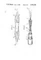
- FIG. 1is a partially cut-away section through a connection as a whole once completed.
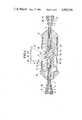
- FIG. 2is a perspective view of the end of a cable showing its various components and approximately full-scale.
- FIG. 3is a schematic longitudinal section showning how fixing parts are positioned on two cable ends to be connected.
- FIG. 4is a section similar to FIG. 3 showing how the fixing parts are mechanically interconnected and how the optical fibers are joined together.
- FIG. 5is a view similar to FIG. 4 showing a filling operation.
- FIG. 6is a view similar to FIG. 5 showing the finished connection.
- FIG. 1is a partially cut-away section through a completed connection between two portions of cable 40 having outer insulating sheaths 16, 16'.
- the connection per se 30comprises a cylindrical housing which is covered by two tapering sleeves 18 and 18' which prevent excessive cable flexing in the vicinity of the connection.
- FIG. 2is a perspective view of the end of the cable 40 showing its component parts.
- the cable 40comprises an optical core 1 housing optical fibers 22, an arch of steel wires 2 wound helically round the fiber-containing core 1, a copper tube 3 swaged down over the arch of steel wires 2, an insulating sheath 4, a return conductor 14 and the outer insulating sheath 16.
- FIG. 3shows the ends of the cable 40 received in a fixing part 8.
- the part 8has a bore with a cylindrical portion 10 which accommodates the copper tube 3 and a conical portion 9 which accommodates the steel wires 2 which are splayed out by a conical wedge 15.
- a moulded plug 11 made of hardenable synthetic resinsfills the free space left by the wedge 15 between the steel wires 2 and the optical core 1.
- a similar arrangementobtains for the other portion of cable 40 which is received in a fixing part 8' having a bore with a cylindrical portion 10' accommodating a copper tube 3' and a conical portion accommodating the steel wires 2' as splayed out by a conical wedge 15'.
- a moulded plug 11' made of hardenable synthetic resinfills the free space left by the wedge 15' between the steel wires 2' and the optical core 1'.
- optical fibers 22 and 22' from the two portions of cable 40pass radially outwardly through ports 12 in the fixing part 8.
- a washer 13 made of an elastomeris interposed between the ends of the two connection parts.
- the two fixing parts 8 and 8'are mechanically connected by an inner tube 23 which is slid over the touching parts 8 and 8' from the same ends as the part 8, and which screws outo the part 8'.
- Mating steps on the part 8 and in the inside wall of the inner tube 23serve to hold the part 8 against the screwed in part 8'.
- the elastomer washer 13serves to compensate for slight dimensional inaccuracies in the machine of the parts 8 and 8' and the inner tube 23, thereby keeping manufacturing costs down.
- Said figureshows two sleeves 28 for joining respective pairs of fiber ends.
- the sleeve 28 at the top of the figureis shown in its fiber-joining position while the sleeve 28 at the bottom of the figure is shown in its final position inside a port 21, through the wall of the inner tube 23.
- the optical fibers 22are welded one to one to optical fibers 22' with a sleeve 28 covering each welded connection.
- Each sleeve 28is then fixed by a tape 27 onto a support thread 26 and then the ends of the thread 26 are received in two grooves 29, 29' machined at each end of each of the ports 21, so that the sleeves 28 are slung hammock like in the ports 21.
- Two orifices 24 and 25 drilled radially through the inner tube 23serve to fill the tube with a water-repellent substance such as polyisobutylene.
- FIG. 4also shows, at each end of the inner tube 23, the arches of steel wires 2 and 2', the copper tubes 3 and 3', the insulating sheaths 4 and 4', the return conductor 14 and 14', and the outer insulating sheaths 16 and 16' of the two portions of cable 40.
- the orifice 24serves to fill the inner tube 23 with polyisobutylene while the orifice 25 serves to vent the inner tube 23 to the outside so as to prevent air bubbles from being trapped inside it during filling.
- the insulating sheaths 4 and 4'are connected together by a sealing mould 31 of plastics material.
- the return conductors 14 and 14'are connected together by a conductive metal braid 32 and, thus reconstituted, serve to earth the device so as to protect operators and also as a return path for repeater power supply current.
- the two protective sheaths 16 and 16'are connected together by a heat-shrinkable sleeve 33.
- optical cores 1 and 1', the arch-forming steel wires 2 and 2', the swaged copper tubes 3 and 3', and the insulating sheaths 4 and 4'are all stripped from the connection zone along a very much longer length than that occupied by the final connection, leaving the optical fibers bare.
- the cable endsneed not have any return conductors.
Landscapes
- Physics & Mathematics (AREA)
- General Physics & Mathematics (AREA)
- Optics & Photonics (AREA)
- Mechanical Coupling Of Light Guides (AREA)
- Light Guides In General And Applications Therefor (AREA)
- Cable Accessories (AREA)
- Communication Cables (AREA)
Abstract
Description
Claims (12)
Applications Claiming Priority (2)
| Application Number | Priority Date | Filing Date | Title |
|---|---|---|---|
| FR8206152 | 1982-04-08 | ||
| FR8206152AFR2524986A1 (en) | 1982-04-08 | 1982-04-08 | DEVICE FOR JOINING THE ENDS OF TWO FIBER OPTIC SUBMARINE CABLES |
Publications (1)
| Publication Number | Publication Date |
|---|---|
| US4595256Atrue US4595256A (en) | 1986-06-17 |
Family
ID=9272892
Family Applications (1)
| Application Number | Title | Priority Date | Filing Date |
|---|---|---|---|
| US06/482,358Expired - Fee RelatedUS4595256A (en) | 1982-04-08 | 1983-04-05 | Connection between the ends of two undersea optical fiber cables and method of manufacturing said connection |
Country Status (6)
| Country | Link |
|---|---|
| US (1) | US4595256A (en) |
| EP (1) | EP0091632B1 (en) |
| JP (1) | JPS58184912A (en) |
| DE (1) | DE3363017D1 (en) |
| FR (1) | FR2524986A1 (en) |
| NO (1) | NO166601C (en) |
Cited By (58)
| Publication number | Priority date | Publication date | Assignee | Title |
|---|---|---|---|---|
| US4657343A (en)* | 1982-10-06 | 1987-04-14 | Standard Telephones And Cables, Public Limited Company | Optical fiber cable and method of jointing two cable elements |
| US4674832A (en)* | 1984-10-12 | 1987-06-23 | Fujikura Ltd. | End assembly for connection to end of ground wire with optical fiber |
| US4711520A (en)* | 1985-07-02 | 1987-12-08 | Litton Systems, Inc. | Fiber optic connector backshell |
| US4773729A (en)* | 1986-12-05 | 1988-09-27 | Les Cables De Lyon | Connection box for optical fiber cables |
| US4790626A (en)* | 1984-12-28 | 1988-12-13 | Les Cables De Lyon | Connection between an optical fiber cable and a junction box |
| GB2205970A (en)* | 1987-06-19 | 1988-12-21 | Ass Elect Ind | Optical cable joint assemblies |
| US4801191A (en)* | 1985-09-25 | 1989-01-31 | The Furukawa Electric Co., Ltd. | Connecting section for optical fiber cable |
| US4813754A (en)* | 1987-03-02 | 1989-03-21 | Societa' Cavi Pirelli S.P.A. | Optical fiber cable joint |
| US4820007A (en)* | 1988-02-12 | 1989-04-11 | American Telephone And Telegraph Company At&T Bell Laboratories | Cable closure and methods of assembling |
| US4846545A (en)* | 1988-03-30 | 1989-07-11 | The United States Of America As Represented By The Secretary Of The Navy | Fiber optic cable connection |
| US4863235A (en)* | 1986-07-21 | 1989-09-05 | American Telephone And Telegraph Company, At&T Bell Laboratories | Connector for optical fiber cable |
| US4993800A (en)* | 1989-05-17 | 1991-02-19 | Yamaichi Electric Mgf. Co., Ltd. | Cable fixing mechanism in a multicore type optical fiber cable connector |
| US5000536A (en)* | 1986-07-21 | 1991-03-19 | At&T Bell Laboratories | Connector for optical fiber cable |
| US5048921A (en)* | 1989-07-14 | 1991-09-17 | Stc Plc | Optical fibre cable joint |
| US5064268A (en)* | 1990-12-07 | 1991-11-12 | The United States Of America As Represented By The Secretary Of The Navy | High pressure fiber optic connector plug |
| US5097526A (en)* | 1989-12-07 | 1992-03-17 | Alcatel N.V. | Connector for two optical cables |
| GB2229545B (en)* | 1989-03-21 | 1993-04-28 | Stc Plc | Jointing optical fibre cables |
| US5241611A (en)* | 1989-10-04 | 1993-08-31 | British Telecommunications Public Limited Company | Cable joint |
| US5278358A (en)* | 1991-05-07 | 1994-01-11 | Alcatel Cable | Under-sea repeater access cable |
| US20060093303A1 (en)* | 2004-11-03 | 2006-05-04 | Randy Reagan | Fiber drop terminal |
| US20060153516A1 (en)* | 2005-01-13 | 2006-07-13 | Napiorkowski John J | Network interface device having integral slack storage compartment |
| US20060233506A1 (en)* | 2005-04-19 | 2006-10-19 | Michael Noonan | Fiber breakout with integral connector |
| US7251411B1 (en) | 2006-03-09 | 2007-07-31 | Adc Telecommunication, Inc. | Fiber optic cable breakout configuration with “Y” block |
| US20070212005A1 (en)* | 2006-03-09 | 2007-09-13 | Adc Telecommunications, Inc. | Mid-span breakout with helical fiber routing |
| US20070212009A1 (en)* | 2006-03-09 | 2007-09-13 | Adc Telecommunications, Inc. | Fiber optic cable breakout configuration with retention block |
| US20070212003A1 (en)* | 2006-03-09 | 2007-09-13 | Adc Telecommunications, Inc. | Mid-span breakout with potted closure |
| US7289714B1 (en) | 2006-09-26 | 2007-10-30 | Adc Telecommunication, Inc. | Tubing wrap procedure |
| US20080037945A1 (en)* | 2006-08-09 | 2008-02-14 | Jeff Gniadek | Cable payout systems and methods |
| US7333708B2 (en) | 2004-01-27 | 2008-02-19 | Corning Cable Systems Llc | Multi-port optical connection terminal |
| US20080080818A1 (en)* | 2006-08-14 | 2008-04-03 | Cobb John C Iii | Factory Spliced Cable Assembly |
| US20080085091A1 (en)* | 2006-10-10 | 2008-04-10 | Dennis Ray Wells | Systems and methods for securing a tether to a distribution cable |
| US20080089652A1 (en)* | 2006-10-13 | 2008-04-17 | Dennis Ray Wells | Overmold zip strip |
| US20080112681A1 (en)* | 2004-02-06 | 2008-05-15 | Battey Jennifer A | Optical connection closure having at least one connector port |
| US20080187274A1 (en)* | 2007-02-06 | 2008-08-07 | Scott Carlson | Polyurethane to polyethylene adhesion process |
| US7418177B2 (en) | 2005-11-10 | 2008-08-26 | Adc Telecommunications, Inc. | Fiber optic cable breakout system, packaging arrangement, and method of installation |
| US7422378B2 (en) | 2006-03-09 | 2008-09-09 | Adc Telecommunications, Inc. | Fiber optic cable breakout configuration with excess fiber length |
| WO2008108622A1 (en)* | 2007-03-07 | 2008-09-12 | Salinas Garcia Jose Marco | Earth conductor having an incorporated connecting part |
| US20080253722A1 (en)* | 2007-04-12 | 2008-10-16 | Erik Gronvall | Fiber optic telecommunications cable assembly |
| US20080253729A1 (en)* | 2007-04-12 | 2008-10-16 | Erik Gronvall | Fiber optic cable breakout configuration with tensile reinforcement |
| US20090022460A1 (en)* | 2006-08-14 | 2009-01-22 | Adc Telecommunications, Inc. | Factory Spliced Cable Assembly |
| US20090060431A1 (en)* | 2007-09-05 | 2009-03-05 | Yu Lu | Indoor Fiber Optic Distribution Cable |
| US7558458B2 (en) | 2007-03-08 | 2009-07-07 | Adc Telecommunications, Inc. | Universal bracket for mounting a drop terminal |
| US7680388B2 (en) | 2004-11-03 | 2010-03-16 | Adc Telecommunications, Inc. | Methods for configuring and testing fiber drop terminals |
| US20100079248A1 (en)* | 2008-09-29 | 2010-04-01 | Johannes Ian Greveling | Optical fiber connector assembly with wire-based RFID antenna |
| US20100092146A1 (en)* | 2008-10-14 | 2010-04-15 | Conner Mark E | Optical Fiber Management Shelf for Optical Connection Terminals |
| US7740409B2 (en) | 2007-09-19 | 2010-06-22 | Corning Cable Systems Llc | Multi-port optical connection terminal |
| US20110175503A1 (en)* | 2008-11-14 | 2011-07-21 | Aravind Chamarti | Equipment cabinet having improved space utilization |
| US8410909B2 (en) | 2010-07-09 | 2013-04-02 | Corning Incorporated | Cables and connector assemblies employing a furcation tube(s) for radio-frequency identification (RFID)-equipped connectors, and related systems and methods |
| US8755663B2 (en) | 2010-10-28 | 2014-06-17 | Corning Cable Systems Llc | Impact resistant fiber optic enclosures and related methods |
| US8873926B2 (en) | 2012-04-26 | 2014-10-28 | Corning Cable Systems Llc | Fiber optic enclosures employing clamping assemblies for strain relief of cables, and related assemblies and methods |
| US8885998B2 (en) | 2010-12-09 | 2014-11-11 | Adc Telecommunications, Inc. | Splice enclosure arrangement for fiber optic cables |
| US8915659B2 (en) | 2010-05-14 | 2014-12-23 | Adc Telecommunications, Inc. | Splice enclosure arrangement for fiber optic cables |
| US9069151B2 (en) | 2011-10-26 | 2015-06-30 | Corning Cable Systems Llc | Composite cable breakout assembly |
| EP2531876A4 (en)* | 2010-02-01 | 2017-12-06 | Tyco Electronics Subsea Communications LLC | Coupling multiple conductor undersea optical cables to an undersea device with an isolated bypass conductive path across the undersea device |
| USD828861S1 (en) | 2016-04-13 | 2018-09-18 | Global Marine Systems Limited | Fiber optic joint |
| US10707633B2 (en)* | 2018-09-27 | 2020-07-07 | Raytheon Company | Plug for an undersea cable |
| EP4002619A1 (en)* | 2020-11-12 | 2022-05-25 | Nexans | Reinforced water barrier over a joint |
| CN115910446A (en)* | 2023-01-07 | 2023-04-04 | 远洋线缆有限公司 | Photovoltaic wind-powered electricity generation is able to bear or endure new forms of energy cable of waiting |
Families Citing this family (8)
| Publication number | Priority date | Publication date | Assignee | Title |
|---|---|---|---|---|
| US4838640A (en)* | 1983-12-19 | 1989-06-13 | Gte Products Corporation | Fiber optic in-line splice case assembly |
| JPS60165906U (en)* | 1984-04-10 | 1985-11-02 | 日立電線株式会社 | Jumper wire for optical composite vehicles |
| JPS60249105A (en)* | 1984-05-25 | 1985-12-09 | Kokusai Denshin Denwa Co Ltd <Kdd> | Construction for detaining optical submarine cable |
| FR2573543B1 (en)* | 1984-11-16 | 1986-12-19 | Cables De Lyon Geoffroy Delore | DEVICE FOR CONNECTING AN OPTICAL FIBER CABLE TO A JUNCTION BOX, AND MANUFACTURING METHOD THEREOF |
| FR2606519B1 (en)* | 1986-11-07 | 1990-07-13 | Pouliquen Georges | SEALING DEVICE FOR PRESSURIZED OPTICAL CABLE AND DEPRESSURIZING CABLE DETECTION SYSTEM USING SUCH A DEVICE |
| FR2630834A1 (en)* | 1988-04-29 | 1989-11-03 | Telecommunications Sa | Improvement to optical links and to termination devices for such links |
| FR2662270B1 (en)* | 1990-05-17 | 1992-07-24 | Alcatel Cable | DEVICE AND METHOD FOR GROWING OPTICAL FIBERS BEYOND A SHEATHED CABLE END. |
| US7068419B2 (en)* | 2004-03-12 | 2006-06-27 | Red Sky Subsea Ltd. | Overmolded, ultra-small form factor optical repeater |
Citations (15)
| Publication number | Priority date | Publication date | Assignee | Title |
|---|---|---|---|---|
| US31515A (en)* | 1861-02-19 | Improvement in ruling-guides for fountain-pens | ||
| US3461539A (en)* | 1966-09-26 | 1969-08-19 | Us Navy | Method of connecting a fiberglass rodlike member to a metallic terminal |
| US4081208A (en)* | 1977-01-17 | 1978-03-28 | General Motors Corporation | Optical and electrical conduit termination means for circuit board |
| DE2729682A1 (en)* | 1977-06-30 | 1979-01-04 | Siemens Ag | Optical fibre junction protection device - has surface protection applied to welded junction point at ends of optical fibres |
| GB2025650A (en)* | 1978-07-18 | 1980-01-23 | Standard Telephones Cables Ltd | Fibre-optic cable joints |
| US4196965A (en)* | 1977-02-11 | 1980-04-08 | Sumitomo Electric Industries, Ltd. | Connecting method of optical fiber with plastic clad |
| GB2030723A (en)* | 1978-10-03 | 1980-04-10 | Standard Telephones Cables Ltd | Fibre-optic Cable Joints |
| DE2847384A1 (en)* | 1978-10-30 | 1980-05-14 | Siemens Ag | High tension proof optical communication cable - with polyurethane epoxy! or polyester filling and sheath of polyethylene, polypropylene, polyurethane or polyester |
| JPS5612607A (en)* | 1979-07-11 | 1981-02-07 | Nippon Telegr & Teleph Corp <Ntt> | Method of holding connected part and extra length part of optical fiber |
| US4264128A (en)* | 1979-11-21 | 1981-04-28 | Bell Telephone Laboratories, Incorporated | Molded optical fiber connectors |
| DE3006131A1 (en)* | 1980-02-19 | 1981-09-03 | Licentia Patent-Verwaltungs-Gmbh, 6000 Frankfurt | Splicing coupling for light wave conductors - has inner core for winding on spare cable and clamping connectors |
| US4330171A (en)* | 1978-09-12 | 1982-05-18 | Socapex | Optical-fiber connector, centering device and method of manufacture of said connector |
| US4412878A (en)* | 1981-04-08 | 1983-11-01 | Societe Anonyme Dite: Les Cables De Lyon | Method of joining together optical fibre undersea cables |
| USRE31515E (en) | 1980-09-18 | 1984-02-07 | Hewlett-Packard Company | Fiber optic connector |
| US4516830A (en)* | 1981-12-30 | 1985-05-14 | Les Cables De Lyon | Junction for joining the ends of two under water optical fiber cables, and method of manufacture |
Family Cites Families (6)
| Publication number | Priority date | Publication date | Assignee | Title |
|---|---|---|---|---|
| US4107451A (en)* | 1975-11-19 | 1978-08-15 | Trech, Inc. | Reinforced splice joint and method of making same |
| GB1595455A (en)* | 1977-05-31 | 1981-08-12 | Standard Telephones Cables Ltd | Submarine optical fibre cables |
| JPS54134652A (en)* | 1978-04-12 | 1979-10-19 | Kokusai Denshin Denwa Co Ltd | Photoofiber holding structure of photoosubmarine repeater |
| GB1580061A (en)* | 1978-05-09 | 1980-11-26 | Standard Telephones Cables Ltd | Fibre optic connector |
| JPS584B2 (en)* | 1979-03-28 | 1983-01-05 | 日本電信電話株式会社 | Optical fiber cable extra length processing section |
| JPS5737315A (en)* | 1980-08-18 | 1982-03-01 | Nippon Telegr & Teleph Corp <Ntt> | Connection part of submarine optical cable |
- 1982
- 1982-04-08FRFR8206152Apatent/FR2524986A1/enactiveGranted
- 1983
- 1983-04-05USUS06/482,358patent/US4595256A/ennot_activeExpired - Fee Related
- 1983-04-05DEDE8383103276Tpatent/DE3363017D1/ennot_activeExpired
- 1983-04-05EPEP83103276Apatent/EP0091632B1/ennot_activeExpired
- 1983-04-06NONO831215Apatent/NO166601C/enunknown
- 1983-04-07JPJP58061492Apatent/JPS58184912A/enactiveGranted
Patent Citations (15)
| Publication number | Priority date | Publication date | Assignee | Title |
|---|---|---|---|---|
| US31515A (en)* | 1861-02-19 | Improvement in ruling-guides for fountain-pens | ||
| US3461539A (en)* | 1966-09-26 | 1969-08-19 | Us Navy | Method of connecting a fiberglass rodlike member to a metallic terminal |
| US4081208A (en)* | 1977-01-17 | 1978-03-28 | General Motors Corporation | Optical and electrical conduit termination means for circuit board |
| US4196965A (en)* | 1977-02-11 | 1980-04-08 | Sumitomo Electric Industries, Ltd. | Connecting method of optical fiber with plastic clad |
| DE2729682A1 (en)* | 1977-06-30 | 1979-01-04 | Siemens Ag | Optical fibre junction protection device - has surface protection applied to welded junction point at ends of optical fibres |
| GB2025650A (en)* | 1978-07-18 | 1980-01-23 | Standard Telephones Cables Ltd | Fibre-optic cable joints |
| US4330171A (en)* | 1978-09-12 | 1982-05-18 | Socapex | Optical-fiber connector, centering device and method of manufacture of said connector |
| GB2030723A (en)* | 1978-10-03 | 1980-04-10 | Standard Telephones Cables Ltd | Fibre-optic Cable Joints |
| DE2847384A1 (en)* | 1978-10-30 | 1980-05-14 | Siemens Ag | High tension proof optical communication cable - with polyurethane epoxy! or polyester filling and sheath of polyethylene, polypropylene, polyurethane or polyester |
| JPS5612607A (en)* | 1979-07-11 | 1981-02-07 | Nippon Telegr & Teleph Corp <Ntt> | Method of holding connected part and extra length part of optical fiber |
| US4264128A (en)* | 1979-11-21 | 1981-04-28 | Bell Telephone Laboratories, Incorporated | Molded optical fiber connectors |
| DE3006131A1 (en)* | 1980-02-19 | 1981-09-03 | Licentia Patent-Verwaltungs-Gmbh, 6000 Frankfurt | Splicing coupling for light wave conductors - has inner core for winding on spare cable and clamping connectors |
| USRE31515E (en) | 1980-09-18 | 1984-02-07 | Hewlett-Packard Company | Fiber optic connector |
| US4412878A (en)* | 1981-04-08 | 1983-11-01 | Societe Anonyme Dite: Les Cables De Lyon | Method of joining together optical fibre undersea cables |
| US4516830A (en)* | 1981-12-30 | 1985-05-14 | Les Cables De Lyon | Junction for joining the ends of two under water optical fiber cables, and method of manufacture |
Cited By (95)
| Publication number | Priority date | Publication date | Assignee | Title |
|---|---|---|---|---|
| US4657343A (en)* | 1982-10-06 | 1987-04-14 | Standard Telephones And Cables, Public Limited Company | Optical fiber cable and method of jointing two cable elements |
| US4674832A (en)* | 1984-10-12 | 1987-06-23 | Fujikura Ltd. | End assembly for connection to end of ground wire with optical fiber |
| US4790626A (en)* | 1984-12-28 | 1988-12-13 | Les Cables De Lyon | Connection between an optical fiber cable and a junction box |
| US4711520A (en)* | 1985-07-02 | 1987-12-08 | Litton Systems, Inc. | Fiber optic connector backshell |
| US4801191A (en)* | 1985-09-25 | 1989-01-31 | The Furukawa Electric Co., Ltd. | Connecting section for optical fiber cable |
| US4863235A (en)* | 1986-07-21 | 1989-09-05 | American Telephone And Telegraph Company, At&T Bell Laboratories | Connector for optical fiber cable |
| US5000536A (en)* | 1986-07-21 | 1991-03-19 | At&T Bell Laboratories | Connector for optical fiber cable |
| US4773729A (en)* | 1986-12-05 | 1988-09-27 | Les Cables De Lyon | Connection box for optical fiber cables |
| US4813754A (en)* | 1987-03-02 | 1989-03-21 | Societa' Cavi Pirelli S.P.A. | Optical fiber cable joint |
| AU600557B2 (en)* | 1987-03-02 | 1990-08-16 | Societa' Cavi Pirelli S.P.A. | Joint for telecommunication cables comprising optical fibres |
| GB2205970A (en)* | 1987-06-19 | 1988-12-21 | Ass Elect Ind | Optical cable joint assemblies |
| GB2205970B (en)* | 1987-06-19 | 1991-03-13 | Ass Elect Ind | A joint assembly for connecting optical fibre cables. |
| US4820007A (en)* | 1988-02-12 | 1989-04-11 | American Telephone And Telegraph Company At&T Bell Laboratories | Cable closure and methods of assembling |
| US4846545A (en)* | 1988-03-30 | 1989-07-11 | The United States Of America As Represented By The Secretary Of The Navy | Fiber optic cable connection |
| GB2229545B (en)* | 1989-03-21 | 1993-04-28 | Stc Plc | Jointing optical fibre cables |
| US4993800A (en)* | 1989-05-17 | 1991-02-19 | Yamaichi Electric Mgf. Co., Ltd. | Cable fixing mechanism in a multicore type optical fiber cable connector |
| US5048921A (en)* | 1989-07-14 | 1991-09-17 | Stc Plc | Optical fibre cable joint |
| US5241611A (en)* | 1989-10-04 | 1993-08-31 | British Telecommunications Public Limited Company | Cable joint |
| US5097526A (en)* | 1989-12-07 | 1992-03-17 | Alcatel N.V. | Connector for two optical cables |
| US5064268A (en)* | 1990-12-07 | 1991-11-12 | The United States Of America As Represented By The Secretary Of The Navy | High pressure fiber optic connector plug |
| US5278358A (en)* | 1991-05-07 | 1994-01-11 | Alcatel Cable | Under-sea repeater access cable |
| US7333708B2 (en) | 2004-01-27 | 2008-02-19 | Corning Cable Systems Llc | Multi-port optical connection terminal |
| US7653282B2 (en) | 2004-01-27 | 2010-01-26 | Corning Cable Systems Llc | Multi-port optical connection terminal |
| US20080112681A1 (en)* | 2004-02-06 | 2008-05-15 | Battey Jennifer A | Optical connection closure having at least one connector port |
| US7805044B2 (en) | 2004-11-03 | 2010-09-28 | Adc Telecommunications, Inc. | Fiber drop terminal |
| US7627222B2 (en) | 2004-11-03 | 2009-12-01 | Adc Telecommunications, Inc. | Fiber drop terminal |
| US20090148120A1 (en)* | 2004-11-03 | 2009-06-11 | Adc Telecommunications, Inc. | Fiber drop terminal |
| US7489849B2 (en) | 2004-11-03 | 2009-02-10 | Adc Telecommunications, Inc. | Fiber drop terminal |
| US9851522B2 (en) | 2004-11-03 | 2017-12-26 | Commscope Technologies Llc | Fiber drop terminal |
| US10042136B2 (en) | 2004-11-03 | 2018-08-07 | Commscope Technologies Llc | Fiber drop terminal |
| US10890729B2 (en) | 2004-11-03 | 2021-01-12 | Commscope Technologies Llc | Fiber drop terminal and bracket |
| US20060093303A1 (en)* | 2004-11-03 | 2006-05-04 | Randy Reagan | Fiber drop terminal |
| US7680388B2 (en) | 2004-11-03 | 2010-03-16 | Adc Telecommunications, Inc. | Methods for configuring and testing fiber drop terminals |
| US11567278B2 (en) | 2004-11-03 | 2023-01-31 | Commscope Technologies Llc | Fiber drop terminal |
| US12204157B2 (en) | 2004-11-03 | 2025-01-21 | Commscope Technologies Llc | Fiber drop terminal |
| US20060153516A1 (en)* | 2005-01-13 | 2006-07-13 | Napiorkowski John J | Network interface device having integral slack storage compartment |
| US7349605B2 (en) | 2005-04-19 | 2008-03-25 | Adc Telecommunications, Inc. | Fiber breakout with radio frequency identification device |
| US8041178B2 (en) | 2005-04-19 | 2011-10-18 | Adc Telecommunications, Inc. | Loop back plug and method |
| US11347008B2 (en) | 2005-04-19 | 2022-05-31 | Commscope Technologies Llc | Fiber optic connection device with ruggedized tethers |
| US20060233506A1 (en)* | 2005-04-19 | 2006-10-19 | Michael Noonan | Fiber breakout with integral connector |
| US20100014824A1 (en)* | 2005-04-19 | 2010-01-21 | Adc Telecommunications, Inc. | Loop back plug and method |
| US20060257092A1 (en)* | 2005-04-19 | 2006-11-16 | Yu Lu | Loop back plug and method |
| US7565055B2 (en) | 2005-04-19 | 2009-07-21 | Adc Telecommunications, Inc. | Loop back plug and method |
| US7418177B2 (en) | 2005-11-10 | 2008-08-26 | Adc Telecommunications, Inc. | Fiber optic cable breakout system, packaging arrangement, and method of installation |
| US20090022459A1 (en)* | 2006-03-09 | 2009-01-22 | Adc Telecommunications, Inc. | Fiber optic cable breakout configuration with retention block |
| US7630606B2 (en) | 2006-03-09 | 2009-12-08 | Adc Telecommunications, Inc. | Fiber optic cable breakout configuration with retention block |
| US7590321B2 (en) | 2006-03-09 | 2009-09-15 | Adc Telecommunications, Inc. | Mid-span breakout with helical fiber routing |
| US20070212003A1 (en)* | 2006-03-09 | 2007-09-13 | Adc Telecommunications, Inc. | Mid-span breakout with potted closure |
| US7424189B2 (en) | 2006-03-09 | 2008-09-09 | Adc Telecommunications, Inc. | Mid-span breakout with potted closure |
| US7317863B2 (en) | 2006-03-09 | 2008-01-08 | Adc Telecommunications, Inc. | Fiber optic cable breakout configuration with retention block |
| US20070212009A1 (en)* | 2006-03-09 | 2007-09-13 | Adc Telecommunications, Inc. | Fiber optic cable breakout configuration with retention block |
| US7251411B1 (en) | 2006-03-09 | 2007-07-31 | Adc Telecommunication, Inc. | Fiber optic cable breakout configuration with “Y” block |
| US7422378B2 (en) | 2006-03-09 | 2008-09-09 | Adc Telecommunications, Inc. | Fiber optic cable breakout configuration with excess fiber length |
| US20100080514A1 (en)* | 2006-03-09 | 2010-04-01 | Adc Telecommunications, Inc. | Fiber optic cable breakout configuration with retention block |
| US20070212005A1 (en)* | 2006-03-09 | 2007-09-13 | Adc Telecommunications, Inc. | Mid-span breakout with helical fiber routing |
| US7599598B2 (en) | 2006-08-09 | 2009-10-06 | Adc Telecommunications, Inc. | Cable payout systems and methods |
| US8121456B2 (en) | 2006-08-09 | 2012-02-21 | Adc Telecommunications, Inc. | Cable payout systems and methods |
| US20080037945A1 (en)* | 2006-08-09 | 2008-02-14 | Jeff Gniadek | Cable payout systems and methods |
| US20080080818A1 (en)* | 2006-08-14 | 2008-04-03 | Cobb John C Iii | Factory Spliced Cable Assembly |
| US7840109B2 (en) | 2006-08-14 | 2010-11-23 | Adc Telecommunications, Inc. | Factory spliced cable assembly |
| US20110286708A1 (en)* | 2006-08-14 | 2011-11-24 | Adc Telecommunications, Inc. | Factory Spliced Cable Assembly |
| US20090022460A1 (en)* | 2006-08-14 | 2009-01-22 | Adc Telecommunications, Inc. | Factory Spliced Cable Assembly |
| US7454106B2 (en) | 2006-08-14 | 2008-11-18 | Adc Telecommunications, Inc. | Factory spliced cable assembly |
| US7289714B1 (en) | 2006-09-26 | 2007-10-30 | Adc Telecommunication, Inc. | Tubing wrap procedure |
| US7480436B2 (en) | 2006-10-10 | 2009-01-20 | Adc Telecommunications, Inc. | Systems and methods for securing a tether to a distribution cable |
| US20080085091A1 (en)* | 2006-10-10 | 2008-04-10 | Dennis Ray Wells | Systems and methods for securing a tether to a distribution cable |
| US7403685B2 (en) | 2006-10-13 | 2008-07-22 | Adc Telecommunications, Inc. | Overmold zip strip |
| US20080089652A1 (en)* | 2006-10-13 | 2008-04-17 | Dennis Ray Wells | Overmold zip strip |
| US7489843B2 (en) | 2007-02-06 | 2009-02-10 | Adc Telecommunications, Inc. | Polyurethane to polyethylene adhesion process |
| US20080187274A1 (en)* | 2007-02-06 | 2008-08-07 | Scott Carlson | Polyurethane to polyethylene adhesion process |
| WO2008108622A1 (en)* | 2007-03-07 | 2008-09-12 | Salinas Garcia Jose Marco | Earth conductor having an incorporated connecting part |
| US7558458B2 (en) | 2007-03-08 | 2009-07-07 | Adc Telecommunications, Inc. | Universal bracket for mounting a drop terminal |
| US20080253729A1 (en)* | 2007-04-12 | 2008-10-16 | Erik Gronvall | Fiber optic cable breakout configuration with tensile reinforcement |
| US7532799B2 (en) | 2007-04-12 | 2009-05-12 | Adc Telecommunications | Fiber optic telecommunications cable assembly |
| US7609925B2 (en) | 2007-04-12 | 2009-10-27 | Adc Telecommunications, Inc. | Fiber optic cable breakout configuration with tensile reinforcement |
| US20080253722A1 (en)* | 2007-04-12 | 2008-10-16 | Erik Gronvall | Fiber optic telecommunications cable assembly |
| US7769261B2 (en) | 2007-09-05 | 2010-08-03 | Adc Telecommunications, Inc. | Fiber optic distribution cable |
| US20090060431A1 (en)* | 2007-09-05 | 2009-03-05 | Yu Lu | Indoor Fiber Optic Distribution Cable |
| US7740409B2 (en) | 2007-09-19 | 2010-06-22 | Corning Cable Systems Llc | Multi-port optical connection terminal |
| US20100079248A1 (en)* | 2008-09-29 | 2010-04-01 | Johannes Ian Greveling | Optical fiber connector assembly with wire-based RFID antenna |
| US20100092146A1 (en)* | 2008-10-14 | 2010-04-15 | Conner Mark E | Optical Fiber Management Shelf for Optical Connection Terminals |
| US20110175503A1 (en)* | 2008-11-14 | 2011-07-21 | Aravind Chamarti | Equipment cabinet having improved space utilization |
| EP2531876A4 (en)* | 2010-02-01 | 2017-12-06 | Tyco Electronics Subsea Communications LLC | Coupling multiple conductor undersea optical cables to an undersea device with an isolated bypass conductive path across the undersea device |
| US9798085B2 (en) | 2010-05-14 | 2017-10-24 | Commscope Technologies Llc | Splice enclosure arrangement for fiber optic cables |
| US8915659B2 (en) | 2010-05-14 | 2014-12-23 | Adc Telecommunications, Inc. | Splice enclosure arrangement for fiber optic cables |
| US8410909B2 (en) | 2010-07-09 | 2013-04-02 | Corning Incorporated | Cables and connector assemblies employing a furcation tube(s) for radio-frequency identification (RFID)-equipped connectors, and related systems and methods |
| US8755663B2 (en) | 2010-10-28 | 2014-06-17 | Corning Cable Systems Llc | Impact resistant fiber optic enclosures and related methods |
| US8885998B2 (en) | 2010-12-09 | 2014-11-11 | Adc Telecommunications, Inc. | Splice enclosure arrangement for fiber optic cables |
| US9069151B2 (en) | 2011-10-26 | 2015-06-30 | Corning Cable Systems Llc | Composite cable breakout assembly |
| US8873926B2 (en) | 2012-04-26 | 2014-10-28 | Corning Cable Systems Llc | Fiber optic enclosures employing clamping assemblies for strain relief of cables, and related assemblies and methods |
| USD828861S1 (en) | 2016-04-13 | 2018-09-18 | Global Marine Systems Limited | Fiber optic joint |
| US10707633B2 (en)* | 2018-09-27 | 2020-07-07 | Raytheon Company | Plug for an undersea cable |
| EP4002619A1 (en)* | 2020-11-12 | 2022-05-25 | Nexans | Reinforced water barrier over a joint |
| US11837386B2 (en) | 2020-11-12 | 2023-12-05 | Nexans | Reinforced water barrier over a joint |
| CN115910446A (en)* | 2023-01-07 | 2023-04-04 | 远洋线缆有限公司 | Photovoltaic wind-powered electricity generation is able to bear or endure new forms of energy cable of waiting |
Also Published As
| Publication number | Publication date |
|---|---|
| EP0091632B1 (en) | 1986-04-16 |
| NO166601B (en) | 1991-05-06 |
| NO831215L (en) | 1983-10-10 |
| JPS58184912A (en) | 1983-10-28 |
| NO166601C (en) | 1991-08-21 |
| EP0091632A1 (en) | 1983-10-19 |
| FR2524986A1 (en) | 1983-10-14 |
| DE3363017D1 (en) | 1986-05-22 |
| FR2524986B1 (en) | 1984-05-25 |
| JPH0358485B2 (en) | 1991-09-05 |
Similar Documents
| Publication | Publication Date | Title |
|---|---|---|
| US4595256A (en) | Connection between the ends of two undersea optical fiber cables and method of manufacturing said connection | |
| US4516830A (en) | Junction for joining the ends of two under water optical fiber cables, and method of manufacture | |
| US4753500A (en) | Joining two optical fiber submarine cable ends | |
| US4784459A (en) | Joining of optical fibre cables | |
| US4601536A (en) | Connection for a submerged optical fiber cable | |
| US4312563A (en) | Connectors for sealed containers | |
| US4580874A (en) | Optical fiber cable repair and joining technique and kit for performing the same | |
| JP2868828B2 (en) | Optical fiber cable splicer | |
| KR940002354B1 (en) | Heser fiber optic cable line | |
| US4545645A (en) | Connection joining the ends of two under-water optical fiber cables and a method of manufacturing same | |
| US4252405A (en) | Fibre-optic cable joints | |
| GB2030723A (en) | Fibre-optic Cable Joints | |
| EP3304665B1 (en) | A rigid joint assembly | |
| EP0110507B1 (en) | Optical fibre cables | |
| US4348076A (en) | Fibre-optic cable joints | |
| US4621168A (en) | Submarine cable joint housing | |
| US4427262A (en) | Armor wire splices | |
| KR930007584B1 (en) | Joint for optical fiber submarine cables | |
| EP0449874B1 (en) | Termination and joint for optical telecommunications cable | |
| US4064358A (en) | Termination for connecting a submarine coaxial cable to a submergible housing | |
| JPH07170645A (en) | Composite cable joint | |
| EP3934039A1 (en) | Conductor connector and cable joint system | |
| WO1994005064A1 (en) | Electric power cable jointing | |
| JPH04151105A (en) | Longitudinal waterproofing device for optical cable cores | |
| US4610737A (en) | Cable splice method using transition rod |
Legal Events
| Date | Code | Title | Description |
|---|---|---|---|
| AS | Assignment | Owner name:LABORATORIES SERONO S.A., CASE POSTALE, 1170 AUBON Free format text:ASSIGNMENT OF ASSIGNORS INTEREST.;ASSIGNOR:SERNA A.G.;REEL/FRAME:004324/0648 Effective date:19840709 | |
| AS | Assignment | Owner name:SOCIETE ANONYME DITE : LES CABLES DE LYON, 170, QU Free format text:ASSIGNMENT OF ASSIGNORS INTEREST.;ASSIGNOR:GUAZZO, LUCIEN;REEL/FRAME:004528/0146 Effective date:19830314 | |
| FEPP | Fee payment procedure | Free format text:PAYOR NUMBER ASSIGNED (ORIGINAL EVENT CODE: ASPN); ENTITY STATUS OF PATENT OWNER: LARGE ENTITY | |
| FPAY | Fee payment | Year of fee payment:4 | |
| FPAY | Fee payment | Year of fee payment:8 | |
| FEPP | Fee payment procedure | Free format text:PAYOR NUMBER ASSIGNED (ORIGINAL EVENT CODE: ASPN); ENTITY STATUS OF PATENT OWNER: LARGE ENTITY Free format text:PAYER NUMBER DE-ASSIGNED (ORIGINAL EVENT CODE: RMPN); ENTITY STATUS OF PATENT OWNER: LARGE ENTITY | |
| REMI | Maintenance fee reminder mailed | ||
| LAPS | Lapse for failure to pay maintenance fees | ||
| FP | Lapsed due to failure to pay maintenance fee | Effective date:19980617 | |
| STCH | Information on status: patent discontinuation | Free format text:PATENT EXPIRED DUE TO NONPAYMENT OF MAINTENANCE FEES UNDER 37 CFR 1.362 |