US4595012A - Lumen mounted electrodes for pacing and intra-cardiac ECG sensing - Google Patents
Lumen mounted electrodes for pacing and intra-cardiac ECG sensingDownload PDFInfo
- Publication number
- US4595012A US4595012AUS06/570,632US57063284AUS4595012AUS 4595012 AUS4595012 AUS 4595012AUS 57063284 AUS57063284 AUS 57063284AUS 4595012 AUS4595012 AUS 4595012A
- Authority
- US
- United States
- Prior art keywords
- electrode
- lumen
- tube
- opening
- extends
- Prior art date
- Legal status (The legal status is an assumption and is not a legal conclusion. Google has not performed a legal analysis and makes no representation as to the accuracy of the status listed.)
- Expired - Lifetime
Links
Images


Classifications
- A—HUMAN NECESSITIES
- A61—MEDICAL OR VETERINARY SCIENCE; HYGIENE
- A61N—ELECTROTHERAPY; MAGNETOTHERAPY; RADIATION THERAPY; ULTRASOUND THERAPY
- A61N1/00—Electrotherapy; Circuits therefor
- A61N1/02—Details
- A61N1/04—Electrodes
- A61N1/05—Electrodes for implantation or insertion into the body, e.g. heart electrode
- A61N1/056—Transvascular endocardial electrode systems
Definitions
- an apparatussuch as a catheter or probe, is inserted through a vein or an artery into the appropriate location within the heart.
- the apparatushas one or more electrodes which are placed in close proximity to the tissue of the heart so that the electrical activity within the heart can be appropriately monitored.
- Intra-cardial ECG sensingcan be done, for example, when the apparatus is within the heart for other purposes.
- temporary pacing of the heartalso requires the making of electrical contact between one or more electrodes of an apparatus, such as a probe or catheter, and the tissue of the heart.
- an apparatussuch as a probe or catheter
- a cathetermay be inserted into the heart to monitor various cardiovascular functions.
- Such a cathetermay be equipped with appropriate pacing electrodes so that, if the patient should suffer a cardiac arrest, the heart can be quickly given the necessary electrical therapy.
- This inventiongreatly reduces the risk of inadvertent removal of the electrode. This is accomplished by mounting the electrode within a lumen of the apparatus and by mounting the mounting means for the electrode at least partially within the lumen. To make demounting of the electrode even less likely and to reduce the likelihood of the electrode forming an impediment to movement of the apparatus, the electrode and the mounting means therefor preferably lie radially inwardly of the body line of the apparatus.
- This inventionis applicable to an apparatus, such as a probe or a catheter, which includes an elongated tube sized to be received through a vein or an artery into the heart and having proximal and distal ends, a peripheral wall, at least one lumen extending longitudinally within the tube, and an opening in the peripheral wall which extends from the lumen to the exterior of the tube.
- the apparatusalso includes an electrode and means at least partially within the lumen for mounting the electrode within the lumen with the electrode being exposed at the opening.
- At least one conductive leadis coupled to the electrode and extends from the electrode within the tube.
- the apparatusmay include any desired number of the electrodes.
- the tubehas a body line, and the electrode preferably extends radially outwardly no farther than the body line.
- the electrodepreferably includes a conductive member with a generally axial passage
- the mounting meansincludes a mounting member in the lumen which extends into the passage to thereby mechanically interlock the mounting member and the conductive member. At least a portion of the mounting member is in the lumen and displaced axially of the opening to form a mechanical interlock with the tube.
- this structureat least assists in mechanically locking the conductive member in the lumen.
- the electrode and the mounting memberform an electrode assembly, and to facilitate insertion of this assembly into the lumen through the opening, the mounting member is preferably resiliently bendable. This characteristic can be enhanced by making the mounting member tubular. However, a stiff mounting member can be used, if desired. In this event, the electrode is inserted through the opening, and subsequently, the tube is bent to allow the relatively stiff mounting member to be inserted through the opening into the lumen and through the electrode.
- the mounting meanspreferably includes an insulating adhesive for bonding the mounting member and the conductive member together and for bonding them to the tube.
- the leadis welded to the electrode and extends through the insulating adhesive.
- the electrodeis preferably positioned within the lumen so that the weld is in the lumen and faces generally away from the opening.
- the apparatusmay include a catheter tube with a balloon, a balloon inflation lumen, and one or more other lumens, such as a through lumen for providing various useful medical functions within the heart.
- FIG. 1is an elevational view of a catheter, with portions broken away, constructed in accordance with the teachings of this invention.
- FIG. 2is an enlarged, sectional view taken generally along line 2--2 of FIG. 1.
- FIG. 3is a fragmentary, axial, sectional view showing the distal tip of the catheter.
- FIG. 4is a plan view showing the electrode assembly prior to its insertion into the lumen.
- FIG. 5is an axial, sectional view through the portions of the catheter which include the electrodes.
- FIG. 6is a sectional view taken generally along line 6--6 of FIG. 5.
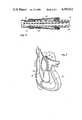
- FIG. 7is a sectional view of the human heart showing one example of how the apparatus of this invention can be used.
- FIG. 1shows an apparatus in the form of a catheter 11 which comprises an elongated catheter tube 13 having a balloon inflation lumen 15 (FIG. 2), a through lumen 17 and an electrode lumen 19.
- a pressure monitoring tube 21 and a balloon inflation tube 23are fused to the tube 13 within the through lumen 17 and the balloon inflation lumen 15, respectively.
- a conduit 25 for insulated electrode leads 27 and 27a(FIG. 2) is fused to the tube 13 within the electrode lumen 19.
- the proximal end of the catheter tube 13 and the distal ends of the tubes 21 and 23 and the conduit 25are encased by a flexible sleeve 29.
- the catheter tube 13may be extruded from a suitable biocompatible plastic material.
- the catheter tube 13is flexible, elongated and sized to be received through a vein or an artery into the heart.
- the catheter tube 13has a proximal end within the sleeve 29 and a distal end 33.
- the balloon inflation lumen 15extends continuously from the proximal end of the tube 13 through a port 35 (FIG. 3) to a balloon 37 closely adjacent the distal end 33.
- the balloon 37 and the manner in which it is inflated through the balloon inflation lumen 15are conventional.
- the through lumen 17extends continuously from the proximal end of the tube 13 to the distal end 33 where it opens at a distal port 39 (FIG. 3).
- the through lumen 17can be used, for example, to monitor pressures within the patient.
- the catheter 11includes a proximal electrode 41 and a distal electrode 43 both of which are mounted within the electrode lumen 19.
- the electrode lumen 19extends continuously from the proximal end of the tube 13 to a location distally of the distal electrode 43.
- the proximal electrodemay be 9.35 to 9.65 inches from the distal end 33
- the distal electrode 43may be 6.2 to 6.4 inches from the distal end 33.
- the catheter 11can be provided with additional lumens, if desired, to provide additional functions for the catheter.
- FIGS. 5 and 6show how the electrodes 41 and 43 are mounted in the electrode lumen 19.
- the electrodes 41 and 43 and their mountingare identical, and accordingly, portions of the mounting structure for the distal electrode corresponding to portions of the mounting structure for the proximal electrode are designated by corresponding reference numerals followed by the letter "a.”
- the electrodes 41 and 43are identical, and each of them, in the illustrated embodiment, is in the form of a tubular conductive member or sleeve of a suitable conductive biocompatible metal, such as stainless steel.
- the catheter tube 13has a peripheral wall 40 (FIG. 5) with openings 42 and 44 (FIG. 6) for exposing portions of the electrodes 41 and 43, respectively.
- the electrode 41has a cylindrical, axial passage 45 extending completely through it and, although various configurations can be used, the electrode 41 is cylindrical.
- the mounting means for the electrode 41includes a tubular, resiliently bendable mounting member 47 of a suitable nontoxic material, such as PVC.
- the mounting member 47is cylindrical and forms a sliding fit with the passage 45 and it has a cylindrical, axial passage 49 extending completely through it.
- the mounting member 47extends completely through the electrode 41 and has end portions 51 and 53 in the lumen 19 on opposite sides of the electrode. As shown in FIG. 5, the end portions 51 and 53 form a mechanical interlock with the catheter tube 13 on opposite sides of the opening 42.
- the mounting meansalso includes an insulating adhesive 59, such as urethane, which bonds the electrode 41 to the mounting member 47 and bonds both of these members within the lumen 19 and to the catheter tube 13.
- the insulating adhesiveincludes sleeve sections 61 which encase regions of the end portions 51 and 53, respectively, and bond the end portions to the confronting surfaces of the lumen 19.
- the adhesive 59preferably includes radial sections 63 which bond the periphery of the opening 42 to the adjacent surfaces of the electrode 41, including end faces 64 of the tube and a portion of the outer periphery.
- a flange section 66overlies a region of the electrode 41 along the full length of the periphery of the opening 42.
- the radial sectionsalso tend to get between the confronting surfaces of the passage 45 and the exterior surface of the mounting member 47 to bond these two members together.
- the adhesive 59includes a dished section 65 (FIG. 6) that bonds the radial inner regions of the electrode 41 to the adjacent surfaces of the lumen 19.
- the dished sections 65partially circumscribe the electrode 41 to tend to retain it securely in position.
- the lead 27has its insulation stripped away at one end, and the electrode 41 is coupled to the lead 27 by a spot weld 67 at such end of the lead.
- the lead 27extends through the adhesive 59, the lumen 19 and the conduit 25 to appropriate electronic equipment (not shown).
- the spot weld 67 and the lead 27are in the lumen 19 and face generally away from the opening 42. In the embodiment illustrated, they are displaced nearly 180 degrees from the center of the opening 42 and, by keeping them away from the opening, they do not reduce the exposed surface area of the electrode 41 and they are not subject to handling or contact of the type that would tend to weaken or separate the joint between them.
- the axial dimension of the electrode 41is only slightly less than the axial dimension of the opening 42.
- the circumferential extent of the opening 42can vary depending upon the desired exposure of the electrode 41. By exposing only a segment of the periphery of the electrode 41, the current density at such electrode is increased to the extent that physical contact between the electrode and heart tissue, when the catheter 11 is used for pacing, may not be required.
- the peripheral wall 40has an outer peripheral surface 69, and the outline of that surface over the opening 42 is a body line 71 of the tube 13.
- the electrode 41extends radially outwardly no farther than about the body line 71, and in the embodiment illustrated, lies slightly radially inwardly of the body line. Thus, the electrode 41 does not extend out of the lumen 19 and the opening 42.
- the mounting member 47does not extend out of the lumen 19, and the insulating adhesive 59 extends radially outwardly no farther than the body line 71.
- the lead 27is welded to the electrode 41 and the weld 67, a length of the lead 27 extending from the weld, and adjacent regions of the electrode and mounting member 47 are covered with a strip 73 (FIG. 4) of a suitable insulating adhesive material, such as urethane.
- a suitable insulating adhesive materialsuch as urethane.
- the leads 27are run through the opening 42 and proximally through the lumen 19. Then the opening 42 and the adjacent regions of the lumen 19 are enlarged by inserting an expander (not shown) through the opening and into the lumen to resiliently expand the plastic material of the catheter tube 13.
- the end portion 51is then inserted through the opening 42 and into the lumen, and the mounting member 47 is resiliently bent until the free end of the end portion 53 can pass through the opening into the lumen 19.
- the electrode assembly 74is then adjusted longitudinally to position the electrode in the opening 42 as shown in FIG. 5.
- the insertion process described aboveis carried out with the weld 67 facing away from the opening 42.
- the plastic material of the catheter tube 13has sufficient memory to recover from the deformation it underwent during the assembly process.
- the insulating adhesive in a flowable, curable stateis applied through the gap between the electrode 41 and the periphery of the opening 42 and allowed to run along the surfaces of the electrode and mounting member to form the sections 61, 63, 65 and 66 as described above.
- the catheter tube 13is introduced through a vein or an artery of a patient and into the heart (FIG. 7) using known techniques.
- the balloon 37is inflated through the balloon inflation lumen 15 and the port 35, and the inflated balloon is used to carry the distal end 33 of the catheter 11 to the desired location.
- the balloon 37is carried into the pulmonary artery 75. Because the electrodes 41 and 43 are mounted in the electrode lumen 19 below the body line 71, they will not rub against any introducer which is used, either during the insertion or withdrawal of the catheter tube 13.
- the location of the catheter tube 13 within the heartwill, of course, depend upon the procedure being carried out.
- the catheter tube 13is inserted into the heart to place the electrodes 41 and 43 in the superior vena cava 77 and the right ventricle 79, respectively.
- the electrodes 41 and 43are in proximity to the heart tissue across the appropriate portion of the heart's electrical field so that they can sense the electrical activity within the heart in a known manner.
- the electrodes 41 and 43may be similarly located.
- the catheter tube 13may be placed within the heart solely for intra-cardial ECG sensing or temporary pacing or for other purposes, such as monitoring of the cardiovascular system.
Landscapes
- Health & Medical Sciences (AREA)
- Heart & Thoracic Surgery (AREA)
- Vascular Medicine (AREA)
- Cardiology (AREA)
- Engineering & Computer Science (AREA)
- Biomedical Technology (AREA)
- Nuclear Medicine, Radiotherapy & Molecular Imaging (AREA)
- Radiology & Medical Imaging (AREA)
- Life Sciences & Earth Sciences (AREA)
- Animal Behavior & Ethology (AREA)
- General Health & Medical Sciences (AREA)
- Public Health (AREA)
- Veterinary Medicine (AREA)
- Electrotherapy Devices (AREA)
Abstract
Description
Claims (16)
Priority Applications (1)
| Application Number | Priority Date | Filing Date | Title |
|---|---|---|---|
| US06/570,632US4595012A (en) | 1984-01-13 | 1984-01-13 | Lumen mounted electrodes for pacing and intra-cardiac ECG sensing |
Applications Claiming Priority (1)
| Application Number | Priority Date | Filing Date | Title |
|---|---|---|---|
| US06/570,632US4595012A (en) | 1984-01-13 | 1984-01-13 | Lumen mounted electrodes for pacing and intra-cardiac ECG sensing |
Publications (1)
| Publication Number | Publication Date |
|---|---|
| US4595012Atrue US4595012A (en) | 1986-06-17 |
Family
ID=24280429
Family Applications (1)
| Application Number | Title | Priority Date | Filing Date |
|---|---|---|---|
| US06/570,632Expired - LifetimeUS4595012A (en) | 1984-01-13 | 1984-01-13 | Lumen mounted electrodes for pacing and intra-cardiac ECG sensing |
Country Status (1)
| Country | Link |
|---|---|
| US (1) | US4595012A (en) |
Cited By (49)
| Publication number | Priority date | Publication date | Assignee | Title |
|---|---|---|---|---|
| US4861330A (en)* | 1987-03-12 | 1989-08-29 | Gene Voss | Cardiac assist device and method |
| US5029585A (en)* | 1989-07-14 | 1991-07-09 | Baxter International Inc. | Comformable intralumen electrodes |
| US5127403A (en)* | 1988-07-05 | 1992-07-07 | Cardiac Control Systems, Inc. | Pacemaker catheter utilizing bipolar electrodes spaced in accordance to the length of a heart depolarization signal |
| US5303704A (en)* | 1992-12-22 | 1994-04-19 | Medtronic, Inc. | Medical electrical lead |
| US5388578A (en)* | 1992-01-14 | 1995-02-14 | Incontrol, Inc. | Electrode system for use with an implantable cardiac patient monitor |
| US6501983B1 (en) | 1998-08-07 | 2002-12-31 | Infinite Biomedical Technologies, Llc | Implantable myocardial ischemia detection, indication and action technology |
| US20050228469A1 (en)* | 2004-04-12 | 2005-10-13 | Cardiac Pacemakers, Inc. | Electrode and conductor interconnect and method therefor |
| US20070049846A1 (en)* | 2005-08-24 | 2007-03-01 | C.R.Bard, Inc. | Stylet Apparatuses and Methods of Manufacture |
| US20090270721A1 (en)* | 2001-12-31 | 2009-10-29 | Abbott Cardiovascular Systems Inc. | Intra-ventricular substance delivery cathether system |
| US20100094116A1 (en)* | 2008-10-07 | 2010-04-15 | Lucent Medical Systems, Inc. | Percutaneous magnetic gastrostomy |
| US20100204569A1 (en)* | 2007-11-26 | 2010-08-12 | C. R. Bard, Inc. | System for placement of a catheter including a signal-generating stylet |
| US7794407B2 (en) | 2006-10-23 | 2010-09-14 | Bard Access Systems, Inc. | Method of locating the tip of a central venous catheter |
| US20100256694A1 (en)* | 2009-04-07 | 2010-10-07 | Boston Scientific Neuromodulation Corporation | Systems and methods for coupling conductors to conductive contacts of electrical stimulation systems |
| US20100317981A1 (en)* | 2009-06-12 | 2010-12-16 | Romedex International Srl | Catheter Tip Positioning Method |
| US20100318026A1 (en)* | 2009-06-12 | 2010-12-16 | Romedex International Srl | Devices and Methods for Endovascular Electrography |
| US20110015533A1 (en)* | 2007-11-26 | 2011-01-20 | C.R. Bard, Inc. | Stylets for use with apparatus for intravascular placement of a catheter |
| US20110196248A1 (en)* | 2009-06-12 | 2011-08-11 | Bard Access Systems, Inc. | Apparatus and method for catheter navigation and tip location |
| US8388546B2 (en) | 2006-10-23 | 2013-03-05 | Bard Access Systems, Inc. | Method of locating the tip of a central venous catheter |
| US8388541B2 (en) | 2007-11-26 | 2013-03-05 | C. R. Bard, Inc. | Integrated system for intravascular placement of a catheter |
| US8478382B2 (en) | 2008-02-11 | 2013-07-02 | C. R. Bard, Inc. | Systems and methods for positioning a catheter |
| USD699359S1 (en) | 2011-08-09 | 2014-02-11 | C. R. Bard, Inc. | Ultrasound probe head |
| US8801693B2 (en) | 2010-10-29 | 2014-08-12 | C. R. Bard, Inc. | Bioimpedance-assisted placement of a medical device |
| US8849382B2 (en) | 2007-11-26 | 2014-09-30 | C. R. Bard, Inc. | Apparatus and display methods relating to intravascular placement of a catheter |
| USD724745S1 (en) | 2011-08-09 | 2015-03-17 | C. R. Bard, Inc. | Cap for an ultrasound probe |
| US9211107B2 (en) | 2011-11-07 | 2015-12-15 | C. R. Bard, Inc. | Ruggedized ultrasound hydrogel insert |
| US9375246B2 (en)* | 2007-01-19 | 2016-06-28 | Covidien Lp | System and method of using thermal and electrical conductivity of tissue |
| US9456766B2 (en) | 2007-11-26 | 2016-10-04 | C. R. Bard, Inc. | Apparatus for use with needle insertion guidance system |
| US9492097B2 (en) | 2007-11-26 | 2016-11-15 | C. R. Bard, Inc. | Needle length determination and calibration for insertion guidance system |
| US9521961B2 (en) | 2007-11-26 | 2016-12-20 | C. R. Bard, Inc. | Systems and methods for guiding a medical instrument |
| US9532724B2 (en) | 2009-06-12 | 2017-01-03 | Bard Access Systems, Inc. | Apparatus and method for catheter navigation using endovascular energy mapping |
| US9554716B2 (en) | 2007-11-26 | 2017-01-31 | C. R. Bard, Inc. | Insertion guidance system for needles and medical components |
| US9649048B2 (en) | 2007-11-26 | 2017-05-16 | C. R. Bard, Inc. | Systems and methods for breaching a sterile field for intravascular placement of a catheter |
| US9839372B2 (en) | 2014-02-06 | 2017-12-12 | C. R. Bard, Inc. | Systems and methods for guidance and placement of an intravascular device |
| US9901714B2 (en) | 2008-08-22 | 2018-02-27 | C. R. Bard, Inc. | Catheter assembly including ECG sensor and magnetic assemblies |
| US10046139B2 (en) | 2010-08-20 | 2018-08-14 | C. R. Bard, Inc. | Reconfirmation of ECG-assisted catheter tip placement |
| JP2019063570A (en)* | 2013-11-22 | 2019-04-25 | ラングペーサー メディカル インコーポレイテッドLungpacer Medical Inc. | catheter |
| US10349890B2 (en) | 2015-06-26 | 2019-07-16 | C. R. Bard, Inc. | Connector interface for ECG-based catheter positioning system |
| US10449330B2 (en) | 2007-11-26 | 2019-10-22 | C. R. Bard, Inc. | Magnetic element-equipped needle assemblies |
| US10524691B2 (en) | 2007-11-26 | 2020-01-07 | C. R. Bard, Inc. | Needle assembly including an aligned magnetic element |
| US10639008B2 (en) | 2009-10-08 | 2020-05-05 | C. R. Bard, Inc. | Support and cover structures for an ultrasound probe head |
| US10751509B2 (en) | 2007-11-26 | 2020-08-25 | C. R. Bard, Inc. | Iconic representations for guidance of an indwelling medical device |
| US10820885B2 (en) | 2012-06-15 | 2020-11-03 | C. R. Bard, Inc. | Apparatus and methods for detection of a removable cap on an ultrasound probe |
| US10973584B2 (en) | 2015-01-19 | 2021-04-13 | Bard Access Systems, Inc. | Device and method for vascular access |
| US10992079B2 (en) | 2018-10-16 | 2021-04-27 | Bard Access Systems, Inc. | Safety-equipped connection systems and methods thereof for establishing electrical connections |
| US11000207B2 (en) | 2016-01-29 | 2021-05-11 | C. R. Bard, Inc. | Multiple coil system for tracking a medical device |
| US11103213B2 (en) | 2009-10-08 | 2021-08-31 | C. R. Bard, Inc. | Spacers for use with an ultrasound probe |
| US11241196B2 (en) | 2020-03-20 | 2022-02-08 | Xenter, Inc. | Signal conducting device for concurrent power and data transfer to and from un-wired sensors attached to a medical device |
| US20240115852A1 (en)* | 2022-10-06 | 2024-04-11 | Medtronic, Inc. | Integrated conductor coil electrode |
| US12403312B2 (en) | 2019-06-12 | 2025-09-02 | Lungpacer Medical Inc. | Circuitry for medical stimulation systems |
Citations (13)
| Publication number | Priority date | Publication date | Assignee | Title |
|---|---|---|---|---|
| US3664347A (en)* | 1968-07-27 | 1972-05-23 | Dietrich Harmjanz | Electric heart stimulation method and electrode |
| US3866615A (en)* | 1973-01-15 | 1975-02-18 | Daigle Claude W | Portable electronic cardiac stimulator |
| US3935864A (en)* | 1973-07-04 | 1976-02-03 | Hans Lagergren | Endocardial electrode |
| US3949757A (en)* | 1974-05-13 | 1976-04-13 | Sabel George H | Catheter for atrio-ventricular pacemaker |
| US3995623A (en)* | 1974-12-23 | 1976-12-07 | American Hospital Supply Corporation | Multipurpose flow-directed catheter |
| US4161952A (en)* | 1977-11-01 | 1979-07-24 | Mieczyslaw Mirowski | Wound wire catheter cardioverting electrode |
| US4172451A (en)* | 1978-04-06 | 1979-10-30 | Medical Evaluation Devices And Instruments Corp. | Intracardial electrode and a method of manufacture thereof |
| US4217910A (en)* | 1978-10-10 | 1980-08-19 | The United States Of America As Represented By The Secretary Of The Navy | Internal jugular and left ventricular thermodilution catheter |
| US4328806A (en)* | 1980-06-18 | 1982-05-11 | American Hospital Supply Corporation | Catheter with trans-luminal gas pathway |
| US4328812A (en)* | 1980-03-21 | 1982-05-11 | Medtronic, Inc. | Ring electrode for pacing lead |
| US4380237A (en)* | 1979-12-03 | 1983-04-19 | Massachusetts General Hospital | Apparatus for making cardiac output conductivity measurements |
| US4402328A (en)* | 1981-04-28 | 1983-09-06 | Telectronics Pty. Limited | Crista terminalis atrial electrode lead |
| US4481953A (en)* | 1981-11-12 | 1984-11-13 | Cordis Corporation | Endocardial lead having helically wound ribbon electrode |
- 1984
- 1984-01-13USUS06/570,632patent/US4595012A/ennot_activeExpired - Lifetime
Patent Citations (14)
| Publication number | Priority date | Publication date | Assignee | Title |
|---|---|---|---|---|
| US3664347A (en)* | 1968-07-27 | 1972-05-23 | Dietrich Harmjanz | Electric heart stimulation method and electrode |
| US3866615A (en)* | 1973-01-15 | 1975-02-18 | Daigle Claude W | Portable electronic cardiac stimulator |
| US3935864B1 (en)* | 1973-07-04 | 1988-11-08 | Endocardial electrode | |
| US3935864A (en)* | 1973-07-04 | 1976-02-03 | Hans Lagergren | Endocardial electrode |
| US3949757A (en)* | 1974-05-13 | 1976-04-13 | Sabel George H | Catheter for atrio-ventricular pacemaker |
| US3995623A (en)* | 1974-12-23 | 1976-12-07 | American Hospital Supply Corporation | Multipurpose flow-directed catheter |
| US4161952A (en)* | 1977-11-01 | 1979-07-24 | Mieczyslaw Mirowski | Wound wire catheter cardioverting electrode |
| US4172451A (en)* | 1978-04-06 | 1979-10-30 | Medical Evaluation Devices And Instruments Corp. | Intracardial electrode and a method of manufacture thereof |
| US4217910A (en)* | 1978-10-10 | 1980-08-19 | The United States Of America As Represented By The Secretary Of The Navy | Internal jugular and left ventricular thermodilution catheter |
| US4380237A (en)* | 1979-12-03 | 1983-04-19 | Massachusetts General Hospital | Apparatus for making cardiac output conductivity measurements |
| US4328812A (en)* | 1980-03-21 | 1982-05-11 | Medtronic, Inc. | Ring electrode for pacing lead |
| US4328806A (en)* | 1980-06-18 | 1982-05-11 | American Hospital Supply Corporation | Catheter with trans-luminal gas pathway |
| US4402328A (en)* | 1981-04-28 | 1983-09-06 | Telectronics Pty. Limited | Crista terminalis atrial electrode lead |
| US4481953A (en)* | 1981-11-12 | 1984-11-13 | Cordis Corporation | Endocardial lead having helically wound ribbon electrode |
Non-Patent Citations (2)
| Title |
|---|
| Mindt et al., "Stimulating Electrode . . .", Med. & Biol. Eng., Sep. 1973, vol. 11, No. 5, pp. 659-660. |
| Mindt et al., Stimulating Electrode . . . , Med. & Biol. Eng., Sep. 1973, vol. 11, No. 5, pp. 659 660.* |
Cited By (113)
| Publication number | Priority date | Publication date | Assignee | Title |
|---|---|---|---|---|
| US4861330A (en)* | 1987-03-12 | 1989-08-29 | Gene Voss | Cardiac assist device and method |
| US5127403A (en)* | 1988-07-05 | 1992-07-07 | Cardiac Control Systems, Inc. | Pacemaker catheter utilizing bipolar electrodes spaced in accordance to the length of a heart depolarization signal |
| US5029585A (en)* | 1989-07-14 | 1991-07-09 | Baxter International Inc. | Comformable intralumen electrodes |
| US5388578A (en)* | 1992-01-14 | 1995-02-14 | Incontrol, Inc. | Electrode system for use with an implantable cardiac patient monitor |
| US5303704A (en)* | 1992-12-22 | 1994-04-19 | Medtronic, Inc. | Medical electrical lead |
| US20030013974A1 (en)* | 1998-08-07 | 2003-01-16 | Ananth Natarajan | Implantable myocardial ischemia detection, indication and action technology |
| US6501983B1 (en) | 1998-08-07 | 2002-12-31 | Infinite Biomedical Technologies, Llc | Implantable myocardial ischemia detection, indication and action technology |
| US7277745B2 (en) | 1998-08-07 | 2007-10-02 | Infinite Biomedical Technologies, Llc | Implantable myocardial ischemia detection, indication and action technology |
| US20070244403A1 (en)* | 1998-08-07 | 2007-10-18 | Ananth Natarajan | Implantable myocardial ischemia detection, indication and action technology |
| US8755870B2 (en) | 1998-08-07 | 2014-06-17 | Infinite Biomedical Technologies, Llc | Implantable myocardial ischemia detection, indication and action technology |
| US8152757B2 (en)* | 2001-12-31 | 2012-04-10 | Advanced Cardiovascular Systems, Inc. | Intra-ventricular substance delivery catheter system |
| US20090270721A1 (en)* | 2001-12-31 | 2009-10-29 | Abbott Cardiovascular Systems Inc. | Intra-ventricular substance delivery cathether system |
| US20050228469A1 (en)* | 2004-04-12 | 2005-10-13 | Cardiac Pacemakers, Inc. | Electrode and conductor interconnect and method therefor |
| US10004875B2 (en) | 2005-08-24 | 2018-06-26 | C. R. Bard, Inc. | Stylet apparatuses and methods of manufacture |
| US11207496B2 (en) | 2005-08-24 | 2021-12-28 | C. R. Bard, Inc. | Stylet apparatuses and methods of manufacture |
| US20070049846A1 (en)* | 2005-08-24 | 2007-03-01 | C.R.Bard, Inc. | Stylet Apparatuses and Methods of Manufacture |
| US8784336B2 (en) | 2005-08-24 | 2014-07-22 | C. R. Bard, Inc. | Stylet apparatuses and methods of manufacture |
| US9265443B2 (en) | 2006-10-23 | 2016-02-23 | Bard Access Systems, Inc. | Method of locating the tip of a central venous catheter |
| US20100331712A1 (en)* | 2006-10-23 | 2010-12-30 | Bard Access Systems, Inc. | Method of locating the tip of a central venous catheter |
| US8858455B2 (en) | 2006-10-23 | 2014-10-14 | Bard Access Systems, Inc. | Method of locating the tip of a central venous catheter |
| US7794407B2 (en) | 2006-10-23 | 2010-09-14 | Bard Access Systems, Inc. | Method of locating the tip of a central venous catheter |
| US9833169B2 (en) | 2006-10-23 | 2017-12-05 | Bard Access Systems, Inc. | Method of locating the tip of a central venous catheter |
| US9345422B2 (en) | 2006-10-23 | 2016-05-24 | Bard Acess Systems, Inc. | Method of locating the tip of a central venous catheter |
| US8388546B2 (en) | 2006-10-23 | 2013-03-05 | Bard Access Systems, Inc. | Method of locating the tip of a central venous catheter |
| US8774907B2 (en) | 2006-10-23 | 2014-07-08 | Bard Access Systems, Inc. | Method of locating the tip of a central venous catheter |
| US8512256B2 (en) | 2006-10-23 | 2013-08-20 | Bard Access Systems, Inc. | Method of locating the tip of a central venous catheter |
| US9375246B2 (en)* | 2007-01-19 | 2016-06-28 | Covidien Lp | System and method of using thermal and electrical conductivity of tissue |
| US11707205B2 (en) | 2007-11-26 | 2023-07-25 | C. R. Bard, Inc. | Integrated system for intravascular placement of a catheter |
| US9554716B2 (en) | 2007-11-26 | 2017-01-31 | C. R. Bard, Inc. | Insertion guidance system for needles and medical components |
| US11123099B2 (en) | 2007-11-26 | 2021-09-21 | C. R. Bard, Inc. | Apparatus for use with needle insertion guidance system |
| US9999371B2 (en) | 2007-11-26 | 2018-06-19 | C. R. Bard, Inc. | Integrated system for intravascular placement of a catheter |
| US8388541B2 (en) | 2007-11-26 | 2013-03-05 | C. R. Bard, Inc. | Integrated system for intravascular placement of a catheter |
| US8781555B2 (en) | 2007-11-26 | 2014-07-15 | C. R. Bard, Inc. | System for placement of a catheter including a signal-generating stylet |
| US11134915B2 (en) | 2007-11-26 | 2021-10-05 | C. R. Bard, Inc. | System for placement of a catheter including a signal-generating stylet |
| US10165962B2 (en) | 2007-11-26 | 2019-01-01 | C. R. Bard, Inc. | Integrated systems for intravascular placement of a catheter |
| US8849382B2 (en) | 2007-11-26 | 2014-09-30 | C. R. Bard, Inc. | Apparatus and display methods relating to intravascular placement of a catheter |
| US20110015533A1 (en)* | 2007-11-26 | 2011-01-20 | C.R. Bard, Inc. | Stylets for use with apparatus for intravascular placement of a catheter |
| US20100204569A1 (en)* | 2007-11-26 | 2010-08-12 | C. R. Bard, Inc. | System for placement of a catheter including a signal-generating stylet |
| US10966630B2 (en) | 2007-11-26 | 2021-04-06 | C. R. Bard, Inc. | Integrated system for intravascular placement of a catheter |
| US10849695B2 (en) | 2007-11-26 | 2020-12-01 | C. R. Bard, Inc. | Systems and methods for breaching a sterile field for intravascular placement of a catheter |
| US10751509B2 (en) | 2007-11-26 | 2020-08-25 | C. R. Bard, Inc. | Iconic representations for guidance of an indwelling medical device |
| US10602958B2 (en) | 2007-11-26 | 2020-03-31 | C. R. Bard, Inc. | Systems and methods for guiding a medical instrument |
| US11529070B2 (en) | 2007-11-26 | 2022-12-20 | C. R. Bard, Inc. | System and methods for guiding a medical instrument |
| US10524691B2 (en) | 2007-11-26 | 2020-01-07 | C. R. Bard, Inc. | Needle assembly including an aligned magnetic element |
| US10449330B2 (en) | 2007-11-26 | 2019-10-22 | C. R. Bard, Inc. | Magnetic element-equipped needle assemblies |
| US10105121B2 (en) | 2007-11-26 | 2018-10-23 | C. R. Bard, Inc. | System for placement of a catheter including a signal-generating stylet |
| US11779240B2 (en) | 2007-11-26 | 2023-10-10 | C. R. Bard, Inc. | Systems and methods for breaching a sterile field for intravascular placement of a catheter |
| US10342575B2 (en) | 2007-11-26 | 2019-07-09 | C. R. Bard, Inc. | Apparatus for use with needle insertion guidance system |
| US10238418B2 (en) | 2007-11-26 | 2019-03-26 | C. R. Bard, Inc. | Apparatus for use with needle insertion guidance system |
| US9456766B2 (en) | 2007-11-26 | 2016-10-04 | C. R. Bard, Inc. | Apparatus for use with needle insertion guidance system |
| US9492097B2 (en) | 2007-11-26 | 2016-11-15 | C. R. Bard, Inc. | Needle length determination and calibration for insertion guidance system |
| US9521961B2 (en) | 2007-11-26 | 2016-12-20 | C. R. Bard, Inc. | Systems and methods for guiding a medical instrument |
| US9526440B2 (en) | 2007-11-26 | 2016-12-27 | C.R. Bard, Inc. | System for placement of a catheter including a signal-generating stylet |
| US10231753B2 (en) | 2007-11-26 | 2019-03-19 | C. R. Bard, Inc. | Insertion guidance system for needles and medical components |
| US9549685B2 (en) | 2007-11-26 | 2017-01-24 | C. R. Bard, Inc. | Apparatus and display methods relating to intravascular placement of a catheter |
| US9681823B2 (en) | 2007-11-26 | 2017-06-20 | C. R. Bard, Inc. | Integrated system for intravascular placement of a catheter |
| US9636031B2 (en) | 2007-11-26 | 2017-05-02 | C.R. Bard, Inc. | Stylets for use with apparatus for intravascular placement of a catheter |
| US9649048B2 (en) | 2007-11-26 | 2017-05-16 | C. R. Bard, Inc. | Systems and methods for breaching a sterile field for intravascular placement of a catheter |
| US8478382B2 (en) | 2008-02-11 | 2013-07-02 | C. R. Bard, Inc. | Systems and methods for positioning a catheter |
| US8971994B2 (en) | 2008-02-11 | 2015-03-03 | C. R. Bard, Inc. | Systems and methods for positioning a catheter |
| US11027101B2 (en) | 2008-08-22 | 2021-06-08 | C. R. Bard, Inc. | Catheter assembly including ECG sensor and magnetic assemblies |
| US9901714B2 (en) | 2008-08-22 | 2018-02-27 | C. R. Bard, Inc. | Catheter assembly including ECG sensor and magnetic assemblies |
| US9907513B2 (en) | 2008-10-07 | 2018-03-06 | Bard Access Systems, Inc. | Percutaneous magnetic gastrostomy |
| US8437833B2 (en) | 2008-10-07 | 2013-05-07 | Bard Access Systems, Inc. | Percutaneous magnetic gastrostomy |
| US20100094116A1 (en)* | 2008-10-07 | 2010-04-15 | Lucent Medical Systems, Inc. | Percutaneous magnetic gastrostomy |
| US8615307B2 (en) | 2009-04-07 | 2013-12-24 | Boston Scientific Neuromodulation Corporation | Systems and methods for coupling conductors to conductive contacts of electrical stimulation systems |
| US20100256694A1 (en)* | 2009-04-07 | 2010-10-07 | Boston Scientific Neuromodulation Corporation | Systems and methods for coupling conductors to conductive contacts of electrical stimulation systems |
| US8214054B2 (en)* | 2009-04-07 | 2012-07-03 | Boston Scientific Neuromodulation Corporation | Systems and methods for coupling conductors to conductive contacts of electrical stimulation systems |
| US9144675B2 (en) | 2009-04-07 | 2015-09-29 | Boston Scientific Neuromodulation Corporation | Systems and methods for coupling conductors to conductive contacts of electrical stimulation systems |
| US9339206B2 (en) | 2009-06-12 | 2016-05-17 | Bard Access Systems, Inc. | Adaptor for endovascular electrocardiography |
| US20100318026A1 (en)* | 2009-06-12 | 2010-12-16 | Romedex International Srl | Devices and Methods for Endovascular Electrography |
| US10231643B2 (en) | 2009-06-12 | 2019-03-19 | Bard Access Systems, Inc. | Apparatus and method for catheter navigation and tip location |
| US10271762B2 (en) | 2009-06-12 | 2019-04-30 | Bard Access Systems, Inc. | Apparatus and method for catheter navigation using endovascular energy mapping |
| US10912488B2 (en) | 2009-06-12 | 2021-02-09 | Bard Access Systems, Inc. | Apparatus and method for catheter navigation and tip location |
| US10349857B2 (en) | 2009-06-12 | 2019-07-16 | Bard Access Systems, Inc. | Devices and methods for endovascular electrography |
| US20100317981A1 (en)* | 2009-06-12 | 2010-12-16 | Romedex International Srl | Catheter Tip Positioning Method |
| US20110196248A1 (en)* | 2009-06-12 | 2011-08-11 | Bard Access Systems, Inc. | Apparatus and method for catheter navigation and tip location |
| US9125578B2 (en) | 2009-06-12 | 2015-09-08 | Bard Access Systems, Inc. | Apparatus and method for catheter navigation and tip location |
| US9445734B2 (en) | 2009-06-12 | 2016-09-20 | Bard Access Systems, Inc. | Devices and methods for endovascular electrography |
| US11419517B2 (en) | 2009-06-12 | 2022-08-23 | Bard Access Systems, Inc. | Apparatus and method for catheter navigation using endovascular energy mapping |
| US9532724B2 (en) | 2009-06-12 | 2017-01-03 | Bard Access Systems, Inc. | Apparatus and method for catheter navigation using endovascular energy mapping |
| US10639008B2 (en) | 2009-10-08 | 2020-05-05 | C. R. Bard, Inc. | Support and cover structures for an ultrasound probe head |
| US11998386B2 (en) | 2009-10-08 | 2024-06-04 | C. R. Bard, Inc. | Support and cover structures for an ultrasound probe head |
| US11103213B2 (en) | 2009-10-08 | 2021-08-31 | C. R. Bard, Inc. | Spacers for use with an ultrasound probe |
| US10046139B2 (en) | 2010-08-20 | 2018-08-14 | C. R. Bard, Inc. | Reconfirmation of ECG-assisted catheter tip placement |
| US8801693B2 (en) | 2010-10-29 | 2014-08-12 | C. R. Bard, Inc. | Bioimpedance-assisted placement of a medical device |
| US9415188B2 (en) | 2010-10-29 | 2016-08-16 | C. R. Bard, Inc. | Bioimpedance-assisted placement of a medical device |
| USD754357S1 (en) | 2011-08-09 | 2016-04-19 | C. R. Bard, Inc. | Ultrasound probe head |
| USD699359S1 (en) | 2011-08-09 | 2014-02-11 | C. R. Bard, Inc. | Ultrasound probe head |
| USD724745S1 (en) | 2011-08-09 | 2015-03-17 | C. R. Bard, Inc. | Cap for an ultrasound probe |
| US9211107B2 (en) | 2011-11-07 | 2015-12-15 | C. R. Bard, Inc. | Ruggedized ultrasound hydrogel insert |
| US10820885B2 (en) | 2012-06-15 | 2020-11-03 | C. R. Bard, Inc. | Apparatus and methods for detection of a removable cap on an ultrasound probe |
| US12239838B2 (en) | 2013-11-22 | 2025-03-04 | Lungpacer Medical Inc. | Apparatus and methods for assisted breathing by transvascular nerve stimulation |
| JP2019063570A (en)* | 2013-11-22 | 2019-04-25 | ラングペーサー メディカル インコーポレイテッドLungpacer Medical Inc. | catheter |
| US11707619B2 (en)* | 2013-11-22 | 2023-07-25 | Lungpacer Medical Inc. | Apparatus and methods for assisted breathing by transvascular nerve stimulation |
| US10863920B2 (en) | 2014-02-06 | 2020-12-15 | C. R. Bard, Inc. | Systems and methods for guidance and placement of an intravascular device |
| US9839372B2 (en) | 2014-02-06 | 2017-12-12 | C. R. Bard, Inc. | Systems and methods for guidance and placement of an intravascular device |
| US10973584B2 (en) | 2015-01-19 | 2021-04-13 | Bard Access Systems, Inc. | Device and method for vascular access |
| US11026630B2 (en) | 2015-06-26 | 2021-06-08 | C. R. Bard, Inc. | Connector interface for ECG-based catheter positioning system |
| US10349890B2 (en) | 2015-06-26 | 2019-07-16 | C. R. Bard, Inc. | Connector interface for ECG-based catheter positioning system |
| US11000207B2 (en) | 2016-01-29 | 2021-05-11 | C. R. Bard, Inc. | Multiple coil system for tracking a medical device |
| US10992079B2 (en) | 2018-10-16 | 2021-04-27 | Bard Access Systems, Inc. | Safety-equipped connection systems and methods thereof for establishing electrical connections |
| US11621518B2 (en) | 2018-10-16 | 2023-04-04 | Bard Access Systems, Inc. | Safety-equipped connection systems and methods thereof for establishing electrical connections |
| US12403312B2 (en) | 2019-06-12 | 2025-09-02 | Lungpacer Medical Inc. | Circuitry for medical stimulation systems |
| US11540776B2 (en) | 2020-03-20 | 2023-01-03 | Xenter, Inc. | Catheter for imaging and measurement of pressure and other physiologic parameters |
| US11751812B2 (en) | 2020-03-20 | 2023-09-12 | Xenter, Inc. | Guidewire for imaging and measurement of pressure and other physiologic parameters |
| US11304659B2 (en)* | 2020-03-20 | 2022-04-19 | Xenter, Inc. | Operatively coupled data and power transfer device for medical guidewires and catheters with sensors |
| US12138077B2 (en) | 2020-03-20 | 2024-11-12 | Xenter, Inc | Operatively coupled data and power transfer device for medical guidewires and catheters with sensors |
| US12213808B2 (en) | 2020-03-20 | 2025-02-04 | Xenter, Inc. | Guidewire for imaging and measurement of pressure and other physiological parameters |
| US11259750B2 (en) | 2020-03-20 | 2022-03-01 | Xenter, Inc. | Guidewire for imaging and measurement of pressure and other physiologic parameters |
| US12268525B2 (en) | 2020-03-20 | 2025-04-08 | Xenter, Inc. | Catheter for imaging and measurement of pressure and other physiological parameters |
| US11241196B2 (en) | 2020-03-20 | 2022-02-08 | Xenter, Inc. | Signal conducting device for concurrent power and data transfer to and from un-wired sensors attached to a medical device |
| US20240115852A1 (en)* | 2022-10-06 | 2024-04-11 | Medtronic, Inc. | Integrated conductor coil electrode |
Similar Documents
| Publication | Publication Date | Title |
|---|---|---|
| US4595012A (en) | Lumen mounted electrodes for pacing and intra-cardiac ECG sensing | |
| US5029585A (en) | Comformable intralumen electrodes | |
| EP0180348B1 (en) | Guiding catheter | |
| US5549581A (en) | Coronary sinus catheter | |
| US4640298A (en) | Esophageal electrode probe useful for electrical stimulation of the heart | |
| US5984909A (en) | Coronary sinus catheter | |
| US6001085A (en) | Coronary sinus catheter | |
| EP0745406B1 (en) | Coronary sinus catheter | |
| US6228052B1 (en) | Dilator for introducer system having injection port | |
| US5653734A (en) | Method of atrial defibrillation employing a temporary implanted catheter | |
| US7195637B2 (en) | Method and device for inserting leads into coronary veins | |
| JP4221492B2 (en) | Method and apparatus for atrial defibrillation | |
| US4681117A (en) | Intracardiac catheter and a method for detecting myocardial ischemia | |
| US10932785B2 (en) | Expandable member for perforation occlusion | |
| US6016437A (en) | Catheter probe system with inflatable soft shafts | |
| US8353900B2 (en) | Miniature circular mapping catheter | |
| US4832048A (en) | Suction ablation catheter | |
| US4759378A (en) | Flexible tip cardiac pacing catheter | |
| US6574512B1 (en) | Lead system with main lead and transverse lead | |
| EP0606688A2 (en) | Intravenous cardiac lead with improved fixation and method | |
| US5827296A (en) | Medical electrical lead | |
| JPH11507251A (en) | Guide catheter for coronary sinus | |
| JPH0128588B2 (en) | ||
| EP2022397A1 (en) | Miniature circular mapping catheter | |
| EP0467422B1 (en) | Guiding catheter |
Legal Events
| Date | Code | Title | Description |
|---|---|---|---|
| AS | Assignment | Owner name:AMERICAN HOSPITAL SUPPLY CORPORATION ONE AMERICAN Free format text:ASSIGNMENT OF ASSIGNORS INTEREST.;ASSIGNORS:WEBLER, WILLIAM E.;LIEBER, CLEMENT;REEL/FRAME:004531/0742 Effective date:19840111 | |
| STCF | Information on status: patent grant | Free format text:PATENTED CASE | |
| AS | Assignment | Owner name:BAXTER TRAVENOL LABORATORIES, INC. A CORP. OF DE Free format text:MERGER;ASSIGNOR:AMERICAN HOSPITAL SUPPLY CORPORATION INTO;REEL/FRAME:004760/0345 Effective date:19870126 | |
| FPAY | Fee payment | Year of fee payment:4 | |
| FEPP | Fee payment procedure | Free format text:PAYOR NUMBER ASSIGNED (ORIGINAL EVENT CODE: ASPN); ENTITY STATUS OF PATENT OWNER: LARGE ENTITY | |
| AS | Assignment | Owner name:BAXTER INTERNATIONAL INC. Free format text:CHANGE OF NAME;ASSIGNOR:BAXTER TRAVENOL LABORATORIES, INC., A CORP. OF DE;REEL/FRAME:005050/0870 Effective date:19880518 | |
| FPAY | Fee payment | Year of fee payment:8 | |
| FEPP | Fee payment procedure | Free format text:PAYOR NUMBER ASSIGNED (ORIGINAL EVENT CODE: ASPN); ENTITY STATUS OF PATENT OWNER: LARGE ENTITY Free format text:PAYER NUMBER DE-ASSIGNED (ORIGINAL EVENT CODE: RMPN); ENTITY STATUS OF PATENT OWNER: LARGE ENTITY | |
| FPAY | Fee payment | Year of fee payment:12 | |
| AS | Assignment | Owner name:EDWARDS LIFESCIENCES CORPORATION, CALIFORNIA Free format text:ASSIGNMENT OF ASSIGNORS INTEREST;ASSIGNOR:BAXTER INTERNATIONAL INC.;REEL/FRAME:010901/0274 Effective date:20000609 |