US4592591A - Housing for seat adjuster locking mechanism - Google Patents
Housing for seat adjuster locking mechanismDownload PDFInfo
- Publication number
- US4592591A US4592591AUS06/539,436US53943683AUS4592591AUS 4592591 AUS4592591 AUS 4592591AUS 53943683 AUS53943683 AUS 53943683AUS 4592591 AUS4592591 AUS 4592591A
- Authority
- US
- United States
- Prior art keywords
- members
- housing
- locking mechanism
- inner peripheral
- fulcrum
- Prior art date
- Legal status (The legal status is an assumption and is not a legal conclusion. Google has not performed a legal analysis and makes no representation as to the accuracy of the status listed.)
- Expired - Lifetime
Links
- 239000004033plasticSubstances0.000claimsabstractdescription3
- 230000002093peripheral effectEffects0.000claimsdescription25
- 238000006073displacement reactionMethods0.000claimsdescription2
- 239000011521glassSubstances0.000claimsdescription2
- 229920005989resinPolymers0.000claimsdescription2
- 239000011347resinSubstances0.000claimsdescription2
- 239000012815thermoplastic materialSubstances0.000claims2
- 239000000463materialSubstances0.000claims1
- 229920002647polyamidePolymers0.000claims1
- 229910000831SteelInorganic materials0.000description3
- 230000000295complement effectEffects0.000description3
- 239000010959steelSubstances0.000description3
- 238000002347injectionMethods0.000description2
- 239000007924injectionSubstances0.000description2
- 239000002184metalSubstances0.000description2
- 239000004677NylonSubstances0.000description1
- 230000000694effectsEffects0.000description1
- 238000001746injection mouldingMethods0.000description1
- 229920001778nylonPolymers0.000description1
- 239000000126substanceSubstances0.000description1
- 229920005992thermoplastic resinPolymers0.000description1
Images


Classifications
- B—PERFORMING OPERATIONS; TRANSPORTING
- B60—VEHICLES IN GENERAL
- B60N—SEATS SPECIALLY ADAPTED FOR VEHICLES; VEHICLE PASSENGER ACCOMMODATION NOT OTHERWISE PROVIDED FOR
- B60N2/00—Seats specially adapted for vehicles; Arrangement or mounting of seats in vehicles
- B60N2/02—Seats specially adapted for vehicles; Arrangement or mounting of seats in vehicles the seat or part thereof being movable, e.g. adjustable
- B60N2/22—Seats specially adapted for vehicles; Arrangement or mounting of seats in vehicles the seat or part thereof being movable, e.g. adjustable the back-rest being adjustable
- B60N2/2227—Seats specially adapted for vehicles; Arrangement or mounting of seats in vehicles the seat or part thereof being movable, e.g. adjustable the back-rest being adjustable and provided with braking systems
- F—MECHANICAL ENGINEERING; LIGHTING; HEATING; WEAPONS; BLASTING
- F16—ENGINEERING ELEMENTS AND UNITS; GENERAL MEASURES FOR PRODUCING AND MAINTAINING EFFECTIVE FUNCTIONING OF MACHINES OR INSTALLATIONS; THERMAL INSULATION IN GENERAL
- F16B—DEVICES FOR FASTENING OR SECURING CONSTRUCTIONAL ELEMENTS OR MACHINE PARTS TOGETHER, e.g. NAILS, BOLTS, CIRCLIPS, CLAMPS, CLIPS OR WEDGES; JOINTS OR JOINTING
- F16B7/00—Connections of rods or tubes, e.g. of non-circular section, mutually, including resilient connections
- F16B7/10—Telescoping systems
- F16B7/14—Telescoping systems locking in intermediate non-discrete positions
- Y—GENERAL TAGGING OF NEW TECHNOLOGICAL DEVELOPMENTS; GENERAL TAGGING OF CROSS-SECTIONAL TECHNOLOGIES SPANNING OVER SEVERAL SECTIONS OF THE IPC; TECHNICAL SUBJECTS COVERED BY FORMER USPC CROSS-REFERENCE ART COLLECTIONS [XRACs] AND DIGESTS
- Y10—TECHNICAL SUBJECTS COVERED BY FORMER USPC
- Y10T—TECHNICAL SUBJECTS COVERED BY FORMER US CLASSIFICATION
- Y10T74/00—Machine element or mechanism
- Y10T74/20—Control lever and linkage systems
- Y10T74/20576—Elements
- Y10T74/20636—Detents
- Y10T74/2066—Friction
Definitions
- the present inventionrelates to a seat adjusting device and more specifically, to a housing for the operative elements of a locking mechanism in an automotive vehicle seat adjusting device of the type which includes a rod pivotally attached to the seat back and slidable for selective positioning within a locking mechanism fixed to the seat.
- a seat adjusting devices of the type which the present invention is directed togenerally include a shaft or rod slidably received within a locking mechanism which includes a plurality of lockwashers slidably mounted on the rod, a fulcrum and a spring or other means biasing the lockwashers about the fulcrum to engage the edge of the lockwasher apertures with the surface of the rod and thereby hold or “lock” the rod in that position relative to the locking mechanism and the seat to which it is fixed.
- a manually actuable release mechanismis usually associated with the locking mechanism to move the lockwashers against the spring or other biasing force and thereby selectively position the rod and seat back relative to the locking mechanism and seat at which point the release mechanism is deactuated thereby permitting the spring or other biasing means to cant the lockwashers into engagement with the rod and thereby hold the selected position.
- the release mechanismis frequently provided in the form of a rotary or pivoting cam actuated by means of a crank lever or a handle.
- Those seat adjusting devicesalso utilize coil springs internally of the housing to bias the lockwashers into engagement with the rod.
- the coil springsrequire a seat or other means opposite the lockwashers and guiding means such as the rod or other projections provided internally of the locking mechanism housing which constitute additional elements and require a more tedious and complex assembly of the seat adjusting device.
- the present inventionprovides a housing for the operative elements of seat adjusting device of the type which includes a rod secured for adjustment of one part of the seat and axially movable relative to a locking mechanism fixed to another part of the seat for selective locking engagement at different positions on the rod.
- the housingis comprised of two members each of which is formed to provide one wall and a plurality of other walls normal to that wall and defining a cavity complimentary to a portion of the shape of the locking mechanism and an inner peripheral edge.
- the inner peripheral edgesare substantially mirror images and two of the other walls of each member have aligned recesses.
- the two membersare secured together with their respective inner peripheral edges in abutment to enclose the operative elements of the locking mechanism with the rod extending through axially aligned openings provided by the recesses.
- semi-ciruclar recessesare provided in the walls of each member and a plurality of slots and detents are integrally formed in the members with each detent positioned to engage a corresponding slot in the other member and thereby secure the housing members together.
- aperturesare provided in the major wall of each member.
- Each apertureis positioned to be axially aligned with a corresponding aperture in the other member and provide axially spaced circular seats when the housing members are secured together.
- FIG. 1is a perspective view of an automotive vehicle seat which includes the seat adjusting device of the present invention
- FIG. 2is a plan view of the seat adjusting device shown in FIG. 1;
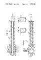
- FIG. 3is a sectional view taken along the line 3--3 of FIG. 2;
- FIG. 4is a front elevation view of the seat adjusting device shown in FIG. 1;
- FIG. 5is a sectional view taken on the line 5--5 of FIG. 3
- FIG. 6is a sectional view taken along line 6--6 of FIG. 3;
- FIG. 7is a sectional view taken along line 7--7 of FIG. 3;
- FIG. 8is a side elevation view of one member of the locking mechanism housing
- FIG. 10is a sectional view taken on line 10--10 of FIG. 8.
- FIG. 11is a sectional view taken on line 11--11 of FIG. 9.
- FIG. 12is a perspective view of the lockwasher biasing spring.
- FIG. 1shows an automotive vehicle seat 10 comprised of a seat portion 11 supported by a frame a portion of the which is shown at 12 and a seat back 14 supported by a pair of side back frames one of which is shown at 15.
- a seat adjusting device 20includes a locking mechanism secured to the seat frame 12 and a rod 22 slidably received within the locking mechanism is pivotally secured by means of a pin 21 at the lower end of the seat back frame 15.
- a seat return coil spring 24is provided between the side frame 15 and the locking mechanism to bias the side frame 15 and seat back 14 to the upright position.
- a manually actuated lever 25is provided to release the locking mechanism threby permitting an occupant of the seat 10 to adjust the seat back 14 to a comfortable position by moving the lever 25 to release the locking mechanism and moving the seat back 14 which in turn will move the side frame and rod 22 relative to the locking mechanism at which time the occupant will release the lever 25 thereby locking the rod 22 and seat back 14 in that selected position.
- the lever 25is seated on the splined end 26 of a shaft 28 rotatably mounted to the locking mechanism generally indicated by the reference numeral 30.
- a return spring 29is seated at one end on the locking mechanism 30 and at the other end on a pin carried by the shaft 28 to return the lever 25 and shaft 28 to its inoperative position upon release.
- the seat return spring 24 coxially with rod 22is seated at its opposite ends against washers 16 and 17.
- the washer 16bears against the housing of locking mechanism 30 to move the rod 22 to its fully extended position as shown in FIGS. 1-3.
- the end of the rod adjacent washer 17is provided with an aperture 19 for receiving the pin 21 which pivotally connects the rod 22 to the lower end of the seat back frame 15 which in turn is pivoted for rocking movement about a pin 18.
- the locking mechanismincludes a plurality of lockwashers 31 and 32, a fulcrum in the form of a hollow steel tube 34, a formed spring 40 and a cam 35 enclosed within a housing 50.
- the lockwasher 31 and 32are apertured with the diameter of the aperture being slightly larger than the diameter of the rod 22 so as to enable the washers to be tilted or canted about the fulcrum tube 32 with an edge of each aperture engaging the surface of the rod 22 with the net effect of the edges of the apertures of all of the lockwashers 31 and 32 preventing relative movement between the rod 22 and the assembly of lockwashers 31 and 32.
- the lockwashersare tilted or canted into engagement with rod 22 by the spring 40 which, as shown by FIGS. 3 and 12 is a formed spring of generally "C" or channel shape having a web portion 41 and a plurality of legs 42-44 and 46-48 at each end of the web.
- the web 41is of sufficient width to extend across the combined thickness of the lockwashers 31 and 32 and is formed with a cylindrical depression 45 which is seated across the bottom of the tubular fulcrum 34 as shown by FIG. 3.
- the legs 42, 44 and 46, 48are spaced so they may extend parallel to the opposite side walls of the housing 50, one on each side of the rod 22 where the legs 42, 44, 46 and 48 contact the lockwashers 31 which are most distant from the fulcrum 44 and cant those, as well as the intermediate lockwashers, into engagement with the rod 22.
- the spring leg 43 located between the legs 42 and 44 and the spring leg 47 located between the legs 46 and 48, although not as long as the legs 42, 44, 46 and 48are nevertheless of sufficient length to extend beyond the axis of the tubular fulcrum 34 and add additional biasing force to urge the lockwashers about the fulcrum 34.
- the spring 40In addition to the locking operation provided by the biasing force of the spring 40, the spring 40 also maintains the stack of lockwashers 31 and 32, the tubular fulcrum 34 and itself as a unit subassembly on the rod 22 during assembly of the seat adjusting device 20.
- the cam 35is integrally formed as part of the shaft 28, see FIG. 5, which is seated for rotation in axially aligned apertures 59 and 69 provided through the locking mechanism housing 50.
- the lockwashers 31, 32are elongate and substantially rectangular in form. As shown by FIGS. 6 and 7, the vertical dimension is greater than the width of the lockwashers 31, 32 and this facilitates a very compact locking mechanism that fits snugly upon the seat frame 12 at the side of the seat.
- the number and specific arrangement of the lockwashers requireddepends upon each particular application.
- two control lockwashers 32are provided as the innermost lockwashers immediately adjacent the fulcrum 34.
- the control lockwashers 32are of greater length at the top of the locking mechanism than are the lockwashers 31 to present a slightly larger area facing the rotary cam 35.
- the locking mechanism housing 50is a two-part housing formed by the combination of a first housing member 51 and a second housing member 61.
- the first housing member 51is formed to provide a major side wall 52 and a plurality of other walls normal to the side wall 52 and defining a cavity complementary to the shape of about half of the locking mechanism per se.
- the edges of the walls normal to the major side wall 52provide an inner peripheral edge surface 54.
- the front and the rear end walls of the housing 52are formed to provide axially aligned semi-circular recesses or bosses 55 and 56.
- a pair of apertures 58 and 59are also provided through the side wall 52 of the housing member 51.
- the inner peripheral edge 54 of the housing member 51is interrupted at several locations by the provision of a hook or detent 57, five of which are shown formed integrally with the first housing member 51.
- the second housing member 61is formed to provide another major side wall 62 and a plurality of other walls normal to the side wall 62 and defining a cavity complementary to the other half of the locking mechanism.
- the outer edges of the walls normal to the major side wall 62define an inner peripheral edge surface 64 which is substantially a mirror image of the shape of the inner peripheral edge 54 of the first housing member 51.
- a pair of axially aligned semi-circular recesses or bosses 65 and 66are provided to the inner peripheral edge 64 of the second housing member 61.
- Portions of the inner peripheral edge 64 of the housing member 61are also flanged as shown by the reference numberal 63 and a plurality of slots 67, five of which are shown, are formed at the inter section of the flanges 63 and one of the other walls normal to the side wall 62 of the housing member 61.
- a pair of apertures 68 and 69are also provided through the side wall 62 of housing member 61.
- the two parts 51 and 61 of the locking mechanism housing 50are formed to be assembled to the seat adjusting device after the lockwashers, fulcrum and spring have been assembled to the rod by placing the housing members 51 and 61 on opposite sides of the rod 22 and applying a slight manual force to secure the two housing members together.
- the inner peripheral edges 54 and 64are formed as mirror images one of the other so that they may be readily placed in abutment.
- the flanges 63 provided about portions of the inner peripheral edge 64 of housing member 61are formed complementary to the outer surfaces of the walls of the housing member 51 to secure the housing members 51 and 61 against lateral displacement when the inner peripheral edges 54 and 64 are placed in abutment.
- Each of the detents 57 of the housing member 51are located opposite one of the slots 67 of the housing member 61 and seat against a reverse surface of the opposing slot thereby securing the housing members 51 and 61 together.
- the semi-circular bosses 55 and 56 of housing member 51are axially algined with each other and with the semi-circular bosses 65, 66 of housing member 61 to surround the rod 22 and thereby permit the rod to extend through the circular apertures provided by the combination of the semi-circular bosses 55 and 65 and 56 and 66.
- the aperture 58 of housing member 51is also aligned on an axis with the aperture 68 of housing member 61 to receive the tubular fulcrum 34.
- the aperture 59 of housing member 51is also axially aligned with the aperture 69 of housing member 61 to receive and rotatably mount axially spaced rotary bearing surfaces of the cam shaft 28.
- the housing members 51 and 61are perferably formed by injection molding a thermoplastic resin and the housing members of the preferred embodiment are injection molded using a 30 percent glass filled nylon resin marketed by Allied Chemical Corporation as Grade 8233.
- the injection molded thermaplastic housing members 51 and 61thus provide a lightweight housing for the locking mechanism which is self-securing and is slidably seated on axially spaced ends of the tubular fulcrum 34.
- the locking mechanism 30is secured to and supported by the channel shaped seat frame 12 by means of a pin slidably received through the interior of the hollow tubular fulcrum 34 and peened 7 or otherwise secured at the interior of the channel shaped seat frame 12.
- the forces developed interiorly of the locking mechanism 30are thus taken at the hollow tubular steel fulcrum 34 independently of the lightweight plastic housing and the fulcrum is attached directly to the seat frame.
- the biasing force of the spring 40 and the releasing force of the cam 35are concentrated directly on the hollow steel tubular fulcrum 34.
Landscapes
- Engineering & Computer Science (AREA)
- General Engineering & Computer Science (AREA)
- Mechanical Engineering (AREA)
- Aviation & Aerospace Engineering (AREA)
- Transportation (AREA)
- Seats For Vehicles (AREA)
- Legs For Furniture In General (AREA)
- Infusion, Injection, And Reservoir Apparatuses (AREA)
- Chairs For Special Purposes, Such As Reclining Chairs (AREA)
Abstract
Description
Claims (12)
Priority Applications (9)
| Application Number | Priority Date | Filing Date | Title |
|---|---|---|---|
| US06/539,436US4592591A (en) | 1983-10-06 | 1983-10-06 | Housing for seat adjuster locking mechanism |
| CA000461535ACA1241264A (en) | 1983-10-06 | 1984-08-22 | Housing for seat adjuster locking mechanism |
| AU32309/84AAU576325B2 (en) | 1983-10-06 | 1984-08-23 | Seat adjustment housing |
| EP84110076AEP0148993A3 (en) | 1983-10-06 | 1984-08-23 | Housing for seat adjuster locking mechanism |
| DE198484110076TDE148993T1 (en) | 1983-10-06 | 1984-08-23 | HOUSING FOR THE LOCKING DEVICE OF A SEAT ADJUSTMENT. |
| MX202691AMX160521A (en) | 1983-10-06 | 1984-09-13 | IMPROVEMENTS TO LATCHING MECHANISM FOR CAR SEAT ADJUSTER |
| BR8404789ABR8404789A (en) | 1983-10-06 | 1984-09-24 | ACCOMMODATION FOR OPERATING ELEMENTS OF SEAT ADJUSTMENT DEVICE AND ACCOMMODATION FOR LOCKING MECHANISM ATTACHED TO A SEAT PART |
| ES1984289613UES289613Y (en) | 1983-10-06 | 1984-10-05 | HOUSING FOR THE OPERATING ELEMENTS OF A SEAT ADJUSTMENT DEVICE. |
| JP59208458AJPS6094837A (en) | 1983-10-06 | 1984-10-05 | Housing |
Applications Claiming Priority (1)
| Application Number | Priority Date | Filing Date | Title |
|---|---|---|---|
| US06/539,436US4592591A (en) | 1983-10-06 | 1983-10-06 | Housing for seat adjuster locking mechanism |
Publications (1)
| Publication Number | Publication Date |
|---|---|
| US4592591Atrue US4592591A (en) | 1986-06-03 |
Family
ID=24151196
Family Applications (1)
| Application Number | Title | Priority Date | Filing Date |
|---|---|---|---|
| US06/539,436Expired - LifetimeUS4592591A (en) | 1983-10-06 | 1983-10-06 | Housing for seat adjuster locking mechanism |
Country Status (9)
| Country | Link |
|---|---|
| US (1) | US4592591A (en) |
| EP (1) | EP0148993A3 (en) |
| JP (1) | JPS6094837A (en) |
| AU (1) | AU576325B2 (en) |
| BR (1) | BR8404789A (en) |
| CA (1) | CA1241264A (en) |
| DE (1) | DE148993T1 (en) |
| ES (1) | ES289613Y (en) |
| MX (1) | MX160521A (en) |
Cited By (11)
| Publication number | Priority date | Publication date | Assignee | Title |
|---|---|---|---|---|
| US4738156A (en)* | 1985-12-30 | 1988-04-19 | A & M Cousin Etablissements Cousin Freres | Rectilinear jack blocked by rollers in an indifferent position |
| US4887864A (en)* | 1988-07-05 | 1989-12-19 | Thomas Ashton | Modular automotive seat frame |
| WO1990002502A1 (en)* | 1988-09-09 | 1990-03-22 | Ab Bd-Produkt Oy | Locking mechanism for a foldable piece of seating furniture |
| US5154492A (en)* | 1990-03-29 | 1992-10-13 | Bendix Europe Services Techniques | Load sensing proportioning valve |
| US5556165A (en)* | 1994-06-17 | 1996-09-17 | Pickles; Joseph | Infinitely adjustable linear actuator for vehicle seat |
| US5582461A (en)* | 1994-06-17 | 1996-12-10 | Itt Automotive, Inc. | Infinitely adjustable linear actuator |
| US5607032A (en)* | 1995-06-07 | 1997-03-04 | Itt Automotive, Inc. | Rotatable shaft lock apparatus |
| US5609066A (en)* | 1990-11-17 | 1997-03-11 | Simplistik Design Limited | Mechanism for actuating a vehicle parking brake |
| US5634534A (en)* | 1996-04-09 | 1997-06-03 | Tachi-S Co., Ltd. | Longitudinal locking mechanism for vehicle seat |
| US6666513B2 (en)* | 2000-12-13 | 2003-12-23 | Lear Corporation | Vehicle seat drive having a mechanical inchworm linear motion actuator |
| CN113879184A (en)* | 2021-09-30 | 2022-01-04 | 厦门金龙汽车座椅有限公司 | A seat mechanism for preventing misoperation in loading |
Citations (7)
| Publication number | Priority date | Publication date | Assignee | Title |
|---|---|---|---|---|
| US176835A (en)* | 1876-05-02 | Improvement in dies for forming trap-sections | ||
| US1650233A (en)* | 1921-01-08 | 1927-11-22 | Hugh E Plunkett | Connecter for electric conduits |
| US3236002A (en)* | 1963-04-24 | 1966-02-22 | Francis V Cunningham | Combination container and spin top |
| US3420032A (en)* | 1965-09-29 | 1969-01-07 | Smith Corp A O | Locking lance tab pre-assembly of box-section frame member |
| US3760480A (en)* | 1969-04-25 | 1973-09-25 | Ledeen Flow Control Systems | Valve operator and method of making the same |
| US4366344A (en)* | 1980-06-13 | 1982-12-28 | Sheehan Robert K | Connector for a helically grooved electrical conductor |
| US4387926A (en)* | 1981-06-26 | 1983-06-14 | Rockwell International Corporation | Seat positioner |
Family Cites Families (1)
| Publication number | Priority date | Publication date | Assignee | Title |
|---|---|---|---|---|
| US3271071A (en)* | 1964-06-22 | 1966-09-06 | Rockwell Standard Co | Position adjusters for seat backs |
- 1983
- 1983-10-06USUS06/539,436patent/US4592591A/ennot_activeExpired - Lifetime
- 1984
- 1984-08-22CACA000461535Apatent/CA1241264A/ennot_activeExpired
- 1984-08-23EPEP84110076Apatent/EP0148993A3/ennot_activeWithdrawn
- 1984-08-23DEDE198484110076Tpatent/DE148993T1/enactivePending
- 1984-08-23AUAU32309/84Apatent/AU576325B2/ennot_activeCeased
- 1984-09-13MXMX202691Apatent/MX160521A/enunknown
- 1984-09-24BRBR8404789Apatent/BR8404789A/enunknown
- 1984-10-05JPJP59208458Apatent/JPS6094837A/enactivePending
- 1984-10-05ESES1984289613Upatent/ES289613Y/ennot_activeExpired
Patent Citations (7)
| Publication number | Priority date | Publication date | Assignee | Title |
|---|---|---|---|---|
| US176835A (en)* | 1876-05-02 | Improvement in dies for forming trap-sections | ||
| US1650233A (en)* | 1921-01-08 | 1927-11-22 | Hugh E Plunkett | Connecter for electric conduits |
| US3236002A (en)* | 1963-04-24 | 1966-02-22 | Francis V Cunningham | Combination container and spin top |
| US3420032A (en)* | 1965-09-29 | 1969-01-07 | Smith Corp A O | Locking lance tab pre-assembly of box-section frame member |
| US3760480A (en)* | 1969-04-25 | 1973-09-25 | Ledeen Flow Control Systems | Valve operator and method of making the same |
| US4366344A (en)* | 1980-06-13 | 1982-12-28 | Sheehan Robert K | Connector for a helically grooved electrical conductor |
| US4387926A (en)* | 1981-06-26 | 1983-06-14 | Rockwell International Corporation | Seat positioner |
Cited By (12)
| Publication number | Priority date | Publication date | Assignee | Title |
|---|---|---|---|---|
| US4738156A (en)* | 1985-12-30 | 1988-04-19 | A & M Cousin Etablissements Cousin Freres | Rectilinear jack blocked by rollers in an indifferent position |
| US4887864A (en)* | 1988-07-05 | 1989-12-19 | Thomas Ashton | Modular automotive seat frame |
| WO1990002502A1 (en)* | 1988-09-09 | 1990-03-22 | Ab Bd-Produkt Oy | Locking mechanism for a foldable piece of seating furniture |
| US5211444A (en)* | 1988-09-09 | 1993-05-18 | Ab Bd Produkt Oy | Locking mechanism for a foldable piece of seating furniture |
| US5154492A (en)* | 1990-03-29 | 1992-10-13 | Bendix Europe Services Techniques | Load sensing proportioning valve |
| US5609066A (en)* | 1990-11-17 | 1997-03-11 | Simplistik Design Limited | Mechanism for actuating a vehicle parking brake |
| US5556165A (en)* | 1994-06-17 | 1996-09-17 | Pickles; Joseph | Infinitely adjustable linear actuator for vehicle seat |
| US5582461A (en)* | 1994-06-17 | 1996-12-10 | Itt Automotive, Inc. | Infinitely adjustable linear actuator |
| US5607032A (en)* | 1995-06-07 | 1997-03-04 | Itt Automotive, Inc. | Rotatable shaft lock apparatus |
| US5634534A (en)* | 1996-04-09 | 1997-06-03 | Tachi-S Co., Ltd. | Longitudinal locking mechanism for vehicle seat |
| US6666513B2 (en)* | 2000-12-13 | 2003-12-23 | Lear Corporation | Vehicle seat drive having a mechanical inchworm linear motion actuator |
| CN113879184A (en)* | 2021-09-30 | 2022-01-04 | 厦门金龙汽车座椅有限公司 | A seat mechanism for preventing misoperation in loading |
Also Published As
| Publication number | Publication date |
|---|---|
| JPS6094837A (en) | 1985-05-28 |
| CA1241264A (en) | 1988-08-30 |
| MX160521A (en) | 1990-03-15 |
| EP0148993A2 (en) | 1985-07-24 |
| AU576325B2 (en) | 1988-08-25 |
| ES289613Y (en) | 1986-10-01 |
| ES289613U (en) | 1986-03-01 |
| AU3230984A (en) | 1985-04-18 |
| BR8404789A (en) | 1985-08-13 |
| DE148993T1 (en) | 1985-11-07 |
| EP0148993A3 (en) | 1988-05-04 |
Similar Documents
| Publication | Publication Date | Title |
|---|---|---|
| US4552405A (en) | Support for seat adjusting device | |
| US4592591A (en) | Housing for seat adjuster locking mechanism | |
| AU689646B2 (en) | Adjustable truck mirror | |
| US4191422A (en) | Adjustable headrest | |
| US7331557B2 (en) | Furniture drive embodied as a double drive | |
| KR100336010B1 (en) | Back support with variable vertices | |
| US4770465A (en) | Locking mechanism for seat adjuster | |
| CA2244430A1 (en) | Rotary gear lock seat recliner | |
| PL177741B1 (en) | Apparatus for adjusting extension height of automobile seat headrest supporting rods | |
| US5013087A (en) | Seat having adjustable lumbar support | |
| KR200144740Y1 (en) | Armrest Angle Adjuster | |
| JPS6312010B2 (en) | ||
| US3433906A (en) | Lever switch having means to avoid transient switching | |
| JPS639762Y2 (en) | ||
| KR200150625Y1 (en) | Reclining knob of car front seat | |
| JPS6123477Y2 (en) | ||
| JPH0710598Y2 (en) | Lumbar support | |
| JPH0124652B2 (en) | ||
| JP3745417B2 (en) | Vehicle seat slide device | |
| JPH0414212Y2 (en) | ||
| JPH06181828A (en) | Moderation imparting mechanism for turning member | |
| JPH0515241Y2 (en) | ||
| JP2000229018A (en) | Movable headrest device | |
| JPS6318488B2 (en) | ||
| JPH07275065A (en) | Seat reclining device |
Legal Events
| Date | Code | Title | Description |
|---|---|---|---|
| AS | Assignment | Owner name:ROCKWELL INTERNATIONAL CORPORATION, PITTSBURGH, PA Free format text:ASSIGNMENT OF ASSIGNORS INTEREST.;ASSIGNOR:WIERS, JOHN W.;REEL/FRAME:004182/0972 Effective date:19831005 | |
| STCF | Information on status: patent grant | Free format text:PATENTED CASE | |
| FEPP | Fee payment procedure | Free format text:PAYOR NUMBER ASSIGNED (ORIGINAL EVENT CODE: ASPN); ENTITY STATUS OF PATENT OWNER: LARGE ENTITY | |
| FPAY | Fee payment | Year of fee payment:4 | |
| FPAY | Fee payment | Year of fee payment:8 | |
| FPAY | Fee payment | Year of fee payment:12 | |
| AS | Assignment | Owner name:ROCKWELL LIGHT VEHICLE SYSTEMS, INC., MICHIGAN Free format text:ASSIGNMENT OF ASSIGNORS INTEREST;ASSIGNOR:ROCKWELL INTERNATIONAL CORPORATION;REEL/FRAME:010425/0106 Effective date:19961115 Owner name:MERITOR LIGHT VEHICLE SYSTEMS, INC., MICHIGAN Free format text:CHANGE OF NAME;ASSIGNOR:ROCKWELL LIGHT VEHICLE SYSTEMS, INC.;REEL/FRAME:010437/0703 Effective date:19970814 | |
| AS | Assignment | Owner name:DURA OPERATING CORP., MICHIGAN Free format text:ASSIGNMENT OF ASSIGNORS INTEREST;ASSIGNOR:MERITOR LIGHT VEHICLE SYSTEMS, INC.;REEL/FRAME:010506/0914 Effective date:19991130 |