US4592359A - Multi-channel implantable neural stimulator - Google Patents
Multi-channel implantable neural stimulatorDownload PDFInfo
- Publication number
- US4592359A US4592359AUS06/719,231US71923185AUS4592359AUS 4592359 AUS4592359 AUS 4592359AUS 71923185 AUS71923185 AUS 71923185AUS 4592359 AUS4592359 AUS 4592359A
- Authority
- US
- United States
- Prior art keywords
- charge
- current
- channel
- stimulator
- channels
- Prior art date
- Legal status (The legal status is an assumption and is not a legal conclusion. Google has not performed a legal analysis and makes no representation as to the accuracy of the status listed.)
- Expired - Fee Related
Links
- 230000001537neural effectEffects0.000titleclaimsabstractdescription10
- 230000007704transitionEffects0.000claimsabstractdescription32
- 239000003990capacitorSubstances0.000claimsabstractdescription15
- 230000000903blocking effectEffects0.000claimsabstractdescription11
- 230000000638stimulationEffects0.000claimsdescription12
- 230000008878couplingEffects0.000claimsdescription4
- 238000010168coupling processMethods0.000claimsdescription4
- 238000005859coupling reactionMethods0.000claimsdescription4
- 210000005036nerveAnatomy0.000claimsdescription4
- 230000000541pulsatile effectEffects0.000abstractdescription23
- 230000008468bone growthEffects0.000abstractdescription4
- 238000011084recoveryMethods0.000abstractdescription2
- 238000013461designMethods0.000description8
- 230000004936stimulating effectEffects0.000description7
- 230000002123temporal effectEffects0.000description7
- 230000000694effectsEffects0.000description6
- 239000007943implantSubstances0.000description6
- 238000010586diagramMethods0.000description5
- 238000012358sourcingMethods0.000description5
- 230000009471actionEffects0.000description4
- 238000013459approachMethods0.000description4
- 210000000860cochlear nerveAnatomy0.000description4
- 238000001514detection methodMethods0.000description4
- 206010011878DeafnessDiseases0.000description3
- 230000008901benefitEffects0.000description3
- 238000000034methodMethods0.000description3
- 210000001519tissueAnatomy0.000description3
- 230000002051biphasic effectEffects0.000description2
- 230000008859changeEffects0.000description2
- 238000005868electrolysis reactionMethods0.000description2
- 230000006870functionEffects0.000description2
- 230000001939inductive effectEffects0.000description2
- 238000004519manufacturing processMethods0.000description2
- 239000000463materialSubstances0.000description2
- 230000007246mechanismEffects0.000description2
- BASFCYQUMIYNBI-UHFFFAOYSA-NplatinumChemical compound[Pt]BASFCYQUMIYNBI-UHFFFAOYSA-N0.000description2
- 230000003334potential effectEffects0.000description2
- 230000008569processEffects0.000description2
- 238000012545processingMethods0.000description2
- 230000001360synchronised effectEffects0.000description2
- 230000032683agingEffects0.000description1
- 230000005540biological transmissionEffects0.000description1
- 230000001413cellular effectEffects0.000description1
- 210000003477cochleaAnatomy0.000description1
- 230000000295complement effectEffects0.000description1
- 230000001276controlling effectEffects0.000description1
- 230000001419dependent effectEffects0.000description1
- 238000005516engineering processMethods0.000description1
- 238000007667floatingMethods0.000description1
- 230000010370hearing lossEffects0.000description1
- 231100000888hearing lossToxicity0.000description1
- 208000016354hearing loss diseaseDiseases0.000description1
- 230000001976improved effectEffects0.000description1
- 239000000203mixtureSubstances0.000description1
- 210000003205muscleAnatomy0.000description1
- 230000000737periodic effectEffects0.000description1
- 229910052697platinumInorganic materials0.000description1
- 230000002028prematureEffects0.000description1
- 230000001902propagating effectEffects0.000description1
- 238000013138pruningMethods0.000description1
- 230000009467reductionEffects0.000description1
- 230000001105regulatory effectEffects0.000description1
- 238000009877renderingMethods0.000description1
- 238000011160researchMethods0.000description1
- 230000000630rising effectEffects0.000description1
- 238000005070samplingMethods0.000description1
- 229920006395saturated elastomerPolymers0.000description1
- 230000035807sensationEffects0.000description1
- 230000035945sensitivityEffects0.000description1
- 230000003068static effectEffects0.000description1
- 230000001629suppressionEffects0.000description1
- 238000001356surgical procedureMethods0.000description1
- 238000012360testing methodMethods0.000description1
- 230000004304visual acuityEffects0.000description1
Images


Classifications
- A—HUMAN NECESSITIES
- A61—MEDICAL OR VETERINARY SCIENCE; HYGIENE
- A61N—ELECTROTHERAPY; MAGNETOTHERAPY; RADIATION THERAPY; ULTRASOUND THERAPY
- A61N1/00—Electrotherapy; Circuits therefor
- A61N1/18—Applying electric currents by contact electrodes
- A61N1/32—Applying electric currents by contact electrodes alternating or intermittent currents
- A61N1/36—Applying electric currents by contact electrodes alternating or intermittent currents for stimulation
- A61N1/36036—Applying electric currents by contact electrodes alternating or intermittent currents for stimulation of the outer, middle or inner ear
- A61N1/36038—Cochlear stimulation
Definitions
- This inventionis directed generally to the field of biomedical engineering and more particularly, the design of an implantable receiver stimulator of an auditory prosthesis system.
- the profoundly deafare individuals whose hearing loss is greater than 90 db. For most, no surgery or other treatment exists that can restore their hearing.
- the auditory prosthesiselectrically stimulates neural tissue, producing the sensation of sound, restoring hearing to the profoundly deaf.
- An auditory prosthesis systemconsists essentially of four parts: the speech processing hardware, the power and data transmitter, the implanted receiver/stimulator, and the implanted electrodes.
- the external electronics to perform the speech processingare the subject of a separated body of technology and are not a part of this patent application.
- the coupling through the skinis achieved using the simultaneously filed application of Mr. Galbraith entitled “A Wide Band Inductive Transdermal Power and Data Link", Ser. No. 719,232 filed 4-2-85 incorporated herein by reference.
- This systemtakes the digitally encoded signals and transmits them, along with power, through the skin into the implanted stimulator.
- the stimulatordecodes the bit stream and delivers charge or current waveforms into electrodes implanted in the auditory nerve or cochlea.
- FIG. 1illustrates two of these requirements as achieved in the prior art, FIG. 1A, and as achieved in the present invention, FIG. 1B.
- the waveformsare charge balanced; i.e., they are biphasic current pulses with equal areas enclosed under both phases. This is necessary because a net DC charge would promote bone growth that could destroy the neural tissue with which the stimulator is interfacing, rendering the implant useless.
- a charge imbalanced waveformcauses electrolysis at the surface of the implanted electrodes. Electrolysis ejects material from the electrode, and can lower the electrode lifetime from years to weeks. The stimulator must therefore recover all the charge delivered to an electrode to prevent neural damage and to insure an adequate implant lifetime.
- the stimulators known in the prior artdelivered many different types of waveforms, an example of which is shown in FIG. 1A. These stimulators metered the charge delivered by controlling the voltage on a capacitor that discharged into an electrode, an approach that controls charge but not current.
- platinum electrodeswhich are those most commonly used and best adapted for implanting can only support a limited charge density before losing material, at or below 400 nC/cm 2 . Therefore, it is an objective of the present invention to limit the charge density below this figure.
- the safety requirements of the stimulating waveformmust enforce charge balancing, charge limiting and current limiting to prevent possible neural damage.
- FIGS. 2A and 2Bshow the waveform formats which were available with prior art stimulators. It is an objective of the present invention to provide the waveforms shown in FIGS. 2C, 2D and 2E, i.e., a quantized analog, a bipolar pulsatile (two rectangular waveforms that are 180° out of phase), and a monopolar pulsatile (rectangular) waveform.
- an adequate stimulatorshould have multiple separate stimulating outputs, possibly eight or more.
- Another objective of the present inventionto provide independent multi-channel operation, an ability lacking in many known stimulators. This is necessary because a successful stimulation algorithm will most likely require multiple independent channels to independently charge different auditory nerves.
- Another objective of the present inventionis to provide a system wherein the resolving power exceeds that of the auditory system.
- Early loudness difference testsshowed that a subject could conclusively resolve down to 1.5 nC or charge difference between two stimulations.
- This charge increment combined with the 250 microamp maximum currentmeans that the minimum timing increment for pulsatile stimulation should be about two microseconds. It is an objective of the present invention to provide an incremental timing resolution down to or below 2 microseconds.
- Yet another objective of the present inventionis to provide a system that is small, portable, and sufficiently efficient to operate for a full day on a set of transistor radio batteries so that it is convenient to use in a practical sense.
- the data formatincludes two types of code words: transition words in which one bit is assigned to each channel and can be used to create monopolar pulsatile or bipolar pulsatile waveforms; and amplitude words which can create analog waveforms one channel at a time.
- An essential element of the output systemis a current source digital to analog converter which responds to the code words to form the appropriate output on each channel.
- Each outputis composed of a set of eight current sources, four with one polarity of current and the other four with the opposite polarity of current.
- the current sourcesare binarily related, I, 2I, 4I and 8I.
- each channelcan supply 16 amplitudes times two polarities of current; meaning 32 current levels. This channel is simply a 5-bit digit to analog converter.
- the output circuitrycontains charge balance switches, something not normally seen in D-to-A converters. These switches are designed to recover residual charge when the current sources are off. They are also designed to current limit during charge recovery if the excess charge is too great so that they do not cause neural damage.
- Each channel charge balances(will not pass DC current or charge) and charge limits to prevent electrode damage and bone growth.
- the charge balancingis performed by the charge balancing switches and by the blocking capacitor.
- the charge limitingis performed by the blocking capacitor only.
- the charge level on each channelis defined using a switch network ladder which combines a plurality of parallel connected switches; closure of each switch doubles the current level handed off from the previous switch.
- FIG. 1illustrates the required properties of the stimulating waveform
- FIG. 2illustrates examples of desired stimulating waveform
- FIG. 3illustrates the data word format used to convey data from transmitter to receiver
- FIG. 4is an illustration which shows schematically the implanted electronics of the auditory prosthesis
- FIGS. 5 and 6are examples of waveforms which can be created using the subject system
- FIG. 7shows the voltage regulators and FM demodulator which are coupled to the receiver portion of the stagger tuned coupling system
- FIGS. 8A and 8Bshow details of the logic chip and the timing to control the logic chip which detects and partially decodes the transmitted data
- FIGS. 9A and 9Bshow in simplified form and in detail the current source chip which responds to the outputs of the logic chip to provide the current signals over the electrodes to stimulate the auditory nerves.
- the coding scheme used to control the implanted systemwill first be described with reference to FIG. 3.
- the three primary goals in designing this codeare:
- the External Timing Control (ETC) Codeis composed of the two words shown in FIG. 3, the "Transition Word” and the "Amplitude Word.” Each word is eleven bits long and begins with a start bit. The data is sent on a serial bit stream with floating word frames, so the start bit indicates the beginning of a word. The parity bit checks for an odd number of bit errors in a word. The ID bit distinguishes between an "Amplitude Word” and a “Transition Word.” The remaining eight bits contain state commands for the "Transition Word” and current level and address commands for the "Amplitude Word.”
- the "Transition Word”is intended to increase the flexibility of the system when used as a pulsatile stimulator, by addressing all eight channels of the multi-electrode stimulus array (FIG. 4) simultaneously.
- a pulsatile outputhas three possible states, both directions of current plus charge balancing. (Charge balancing means shorting the electrode to body ground, thereby recovering the residual charge left on it.) If, in a "Transition Word,” a "one" appears in a given output's bit position, then that output cycles to its next state. If instead a "zero" appears, then that output holds its present state. All eight channels are represented by the last eight bits in the transition word, meaning that the system can simultaneously access them.
- the stimulatorcan produce synchronized or staggered pulses, and it can act as a one to eight channel monopolar stimulator, or a one to four channel bipolar stimulator, or any mixture of the two types.
- the "Amplitude Word”selects the pulsatile state sequence of a given channel. It is also used to create the arbitrary wave-shapes of an analog stimulator. This word is a standard Analog to Digital bit sequence. It has three bits to individually address the eight channels, four bits to adjust the current magnitude, plus one more bit to set the current polarity.
- the magnitude bitsset the peak current of the pulsatile waveforms, while the polarity bit selects one of the two possible pulsatile sequences available for each channel: "sourcing current sinking current charge balancing," or “sinking current sourcing current charge balancing.”
- the polarity bit coupled with the “Transition Word”determines whether a pair of channels deliver monopolar or bipolar stimuli (two synchronized channels with different state sequences can act as a bipolar pair). So the "Amplitude Word” selects the class of stimuli that a channel delivers.
- the “Amplitude Word”is also capable of creating an arbitrary current wave-shape. Once the channels are activated by the "Transition Word” (switched from charge balancing to a current supplying state), the “Amplitude Word” can program 16 magnitudes and two polarities for each channel, creating a quantized analog approximation of the desired signal. At a one megabit per second data rate, the Nyquist sampling frequency for each of eight independent channels is 11,364 KHz, which means the maximum frequency that a channel could pass without aliasing a 5682 Hz, well above the 3 KHz cutoff frequency of a telephone channel (telephone quality bandwidth is generally considered necessary for adequate speech comprehension, without assuming a model for the speech production or decoding mechanism). So, under the worst case conditions, where all eight channels are operating as analog outputs, this code can still provide eight independent channels of quantized analog, each with telephone quality bandwidth.
- the "Transition Word”is optimized for creating pulsatile stimulation. It can simultaneously address all eight channels and, with the help of the polarity bit in the "Amplitude Word,” it can provide monopolar or bipolar stimulation.
- the "Amplitude Word”sets the current levels and state sequence of each channel. It can also create a quantized analog waveform on each channel. So this code provides all three classes of stimulation, monopolar pulsatile, bipolar pulsatile, and quantized analog.
- the periodic resettingis a "catch-all" approach for protection against unstoppable errors.
- An unstoppable erroris a coding mistake in the instructions sent to the package. These generally come from software bugs encountered while implementing a new algorithm or a new hardware system. This could deliver too much charge to an electrode, leave a current source "on,” or deliver a charge imbalanced waveform. The implant volunteer requires protection from these potentially catastrophic mistakes.
- the ETC Codelimits the effects of these mistakes by requiring at least one "Master Reset" every 5 ms to keep the package operational. Otherwise, the unit enters an error state, which is described later. This restriction bounds the effects of an error (detected or otherwise) to one 5 ms interval. It also initiates at least one attempt every 5 ms to charge balance all the electrodes correcting for any missed errors.
- the systemBy shutting down until the next resynchronization instead of continuing operation, the system has stopped an error from propagating into many errors. For instance, one biphasic pulse requires three "Transition Words.” If one of those words contained an error that switched "on" the wrong channel, or did not switch the correct one, then an output would not return to its charge balanced state. Instead, it would continue supplying current, causing a charge imbalance on an electrode, and creating a potential source of failure.
- one bit errorhas lost the synchronization between the outside and inside worlds, and later "Transition Words" are performing unintended tasks. So shutting down after detecting an error limits the effect of an error and prevents one error from growing into many.
- FIG. 5illustrates how to use the ETC Code to create a pulsatile waveform and the results of a detected error.
- the top lineis the control word bit stream sent into the package.
- the next two linesare the current outputs of two channels of the stimulator.
- a pulsatile waveformgenerally relies heavily on “Transition Words” as shown in this example.
- the "Master Reset”is first sent into the package to clear any error conditions and to synchronize the system.
- two “Amplitude Words”set the polarity and magnitude that the current sources of channel 1 and channel 5 deliver when they are turned “on.”
- a "Transition Word”switches these two channels out of their charge balanced state, simultaneously. The switching occurs one bit period after the word is received.
- FIG. 6is an example of the ETC Code producing a quantized analog wave-shape. While the pulsatile example relied primarily on “Transition Words,” creating arbitrary waveforms usually requires using the “Amplitude Word.” The top line of the figure is the input data word stream and the lower line represents the current output of one channel. Again, a “Master Reset” is sent to clear and synchronize the package. Then a “Transition Word” is sent to turn the current source “on.” No current is delivered because the "Master Reset” programmed the outputs to zero current. Now “Amplitude Words” are sent to construct a waveform in a typical D to A pattern.
- the ETC Codewas designed to reduce the number of bits needed to create a signal (or event). By pruning the unnecessary information from the data, the word length is reduced, allowing the transmission of more instructions per unit of time.
- the ETC Codetransmits the state information in the control words and the timing information in the temporal position of each word.
- a word specifying the state of one or more currentsis sent, and the action occurs one bit cycle after the word is received.
- bits containing temporal informationpulse width, pulse position, pulse period, etc.
- the ETC Codealso takes advantage of advance knowledge about the pulsatile wave-shapes (monopolar and bipolar) to further reduce the number of bits needed to create these waveforms.
- Each output channelhas three possible pulsatile states, "sourcing current,” “sinking current,” and “balancing charge.” Defining three states per channel for an eight channel system normally requires 16 bits. But the need for charge balancing generally locks the outputs into the sequence of "current; opposite polarity current; charge balancing.” By specifying a state transition instead of an absolute state, only one bit per channel is needed; cutting the number of data bits from 16 to 8. In other words, the control word does not tell a channel explicitly what job to do. Instead, it tells the channel to stop whatever it is doing and move on to its next job, without stating what the next job is.
- the bit streamis encoded using pulse-duration-modulation.
- a long pulseis a "one” and short pulse is a "zero.”
- PDMwas chosen because the leading edge contains the timing (synchronizing) information, and the simple circuit that decodes it can also use this information to generate the internal clock.
- the clock periodis set by the period of the incoming bits, the user can change the temporal resolution of the package without altering the implanted electronics.
- the packagecan track any data rate slower than its maximum; even to DC (although it flags a bit stream "time out" error when the bit period exceeds 22 ⁇ s).
- This approachhas added the capability of modulating the temporal position of a waveform, and eliminates the requirement of locking a waveform's transitions to a fixed clock period, such as 1 ⁇ s/bit.
- Another advantage of this approachis that it eliminates the problem of synchronizing two clocks, one internal and one external. Though normally not a major problem, it can become serious as components age and time constants change. The package is intended to operate for 10 years, long enough for these problems to surface. By maxing the timing accuracy dependent only on the external electronics, the system should have a dependable clock period for the full 10 years.
- pulse-duration-modulationsimplifies the detector/clock circuitry, adds the capability of temporal modulation, desensitizes the system to component aging and drift, and allows a reduction in the power consumption of the system that may open new applications.
- the stagger-tuned linkproduced a fairly stable output voltage from which to create a regulated voltage supply.
- an efficient voltage regulatorwould operate with a small voltage dropped across it, so that it consumes little power while sourcing large currents. It should also burn a negligible amount of quiescent current for its own operation.
- the regulators used in the stimulatorare close to this ideal. Their circuit diagrams are shown in FIG. 7. These voltage regulators function down to one saturated bipolar transistor drop (0.3 volts) across them at full load current; the quiescent current consumption for both regulators is about 0.25 mA, less than 10 percent of the total stimulator current (3.3 mA maximum).
- These regulatorsare capable of both sourcing and sinking current. This capability provides general protection for the implanted electronics if excessive voltages occur from design oversights. It was added to reduce or eliminate the potential effects of any design oversights.
- This sectiondescribes the circuitry that converts the information sent by the ETC Code into stimulation patterns on the electrodes is disclosed with reference to FIGS. 8, 9 and 10. It covers, in detail, the implementation of the safety requirements. It also provides examples showing the achievement of the principal design goals; producing all three classes of stimulation for flexibility, arbitrary wave-shape for experimental needs, and independent multi-channel operation.
- the logic chip of FIG. 8performs the decoding of the PDM data stream and most of the ECT Code.
- the circuit diagramis shown in FIG. 8A and an example timing diagram is shown in FIG. 8B.
- the PDM decodingis done simply by a D-flip-flop and a one-shot. The rising edge of the PDM signal fires the one-shot and the data is detected on the falling edge by the flip-flop.
- the one-shotalso acts as the clock so that the internal clock tracks the data rate, allowing temporal modulation of the switching information.
- This simple circuitnot only performs detection and clock generation; it also eliminates the need for an accurate internal timing reference since it derives this information from the outside world.
- the rest of the chipcontains the state machines for all eight channels, the logic to decode most of the ETC coded bit stream, and implements most of the protection conditions of the ETC Code.
- This chipexplicitly decodes the transition word that drives the output state machines and that carries the Master Reset.
- This chipperforms the "power on reset,” parity checking, and lost bit stream detection.
- the interface between it and the current source chipperforms the Master Reset time-out detection.
- the circuitryis fully clocked to avoid race conditions. It uses cellular elements to minimize the layout mistakes.
- the clocking one-shotis insensitive to the duration of a bit so that different data rates will not affect the detection period.
- the transistorsare operated nearly two orders of magnitude below their maximum switching frequency so that the circuit can tolerate a large variation in the fabrication process.
- the logic chipoperates at a lower power supply voltage than the current source chip.
- the logic chiponly needs 5 volts of the 13-volt supply to function. Since the power drawn by a CMOS circuit tends to increase with the square of the voltage, the lower supply cuts the power consumption significantly.
- control lines connecting the logic chip to the current source chipare only active when sending information.
- the current source chipmust level shift all the incoming signals from the logic chip and level shifters consume power. So the conservative design ensures safe operation and saves power.
- the logicis implemented using a CMOS gate array (SPI 7005B) from Semi Processes Incorporated.
- the arraycontains roughly 5000 transistors of which about 3000 are used to implement the system logic using known gate array connection techniques.
- the current source chip of FIG. 9performs the final decoding of the amplitude word and provides the coding to current interface to the electrodes. It, along with a few external components, also ensures the safety of the implant by limiting the current and charge, and by providing charge balancing.
- FIG. 9Ashows a conceptual diagram for one channel.
- the switches S o through S 3set the magnitude of the current under control of the Amplitude Word.
- the switches S in and S outdetermine the polarity and are primarily controlled by the transition word.
- Each channelis capable of providing a pulsatile or quantized analog output depending on the switching sequence of these pass gates. For example, to produce a monophasic pulse, simply program the current sources (say turn on S 1 and S 2 ), then alternately switch S out on and S in on.
- the blocking capacitor C Bis an external component that is probably the most important safety element of each stimulating channel. It stops DC current from passing into the electrode. DC current would eventually destroy the electrode, possibly damage the nerves, and promote bone growth.
- the capacitor C Balso acts as a charge limiter. Excessive charge (about 400 nC/phase in this case) causes the electrodes to break down. This capacitor limits the worst case charge to about 300 nC/phase.
- this capacitoris a high reliability pace maker part and since it is the last component between the stimulator and the electrodes, it limits the effects of failures in the electronics leading to the electrodes (such as limiting the output charge of a current source that is stuck "on”). So this capacitor limits the charge, blocks the DC current, and protects against component failures; all of which should prevent damage to the electrodes and nerves.
- the current and charge limits of this systemare not locked by the integrated circuits. Instead, they are programmed by components external to the chip (but still inside the implanted package). This arrangement allows for adjusting the stimulator to new electrodes or new uses. For example, a larger electrode surface area could support higher currents and more charge than the present system is set for.
- the maximum output chargeis determined by the power supply voltage and the size of the blocking capacitor, so a new blocking capacitor sets a new maximum output charge.
- the maximum currentis adjusted, look at the circuit diagram for the current source chip shown in FIG. 9B. Notice that the reference current for all the current sources is set by one external resistor RI. A new resistor sets a new current peak. Therefore, even though the chips are static, the stimulating characteristics of the system are programmable (at least until the package is sealed) and can match the needs of future implants.
- the systemis conservatively designed in an effort to promote reliability. It provides safety and a long electrode lifetime by limiting the current and charge, by blocking any DC current, and by charge balancing. Its current and charge limits are reprogrammable allowing it to adapt to future needs. It is flexible, capable of producing monopolar, bipolar, and analog outputs with few limitations in each class. It can create nonstandard waveforms for research needs, and it provides eight independent channels of stimuli. In summary, it has met its primary goals of safety and flexibility.
Landscapes
- Health & Medical Sciences (AREA)
- Otolaryngology (AREA)
- Engineering & Computer Science (AREA)
- Biomedical Technology (AREA)
- Nuclear Medicine, Radiotherapy & Molecular Imaging (AREA)
- Radiology & Medical Imaging (AREA)
- Life Sciences & Earth Sciences (AREA)
- Animal Behavior & Ethology (AREA)
- General Health & Medical Sciences (AREA)
- Public Health (AREA)
- Veterinary Medicine (AREA)
- Electrotherapy Devices (AREA)
Abstract
Description
This invention is directed generally to the field of biomedical engineering and more particularly, the design of an implantable receiver stimulator of an auditory prosthesis system.
The profoundly deaf are individuals whose hearing loss is greater than 90 db. For most, no surgery or other treatment exists that can restore their hearing. The auditory prosthesis electrically stimulates neural tissue, producing the sensation of sound, restoring hearing to the profoundly deaf.
An auditory prosthesis system consists essentially of four parts: the speech processing hardware, the power and data transmitter, the implanted receiver/stimulator, and the implanted electrodes. The external electronics to perform the speech processing are the subject of a separated body of technology and are not a part of this patent application. The coupling through the skin is achieved using the simultaneously filed application of Mr. Galbraith entitled "A Wide Band Inductive Transdermal Power and Data Link", Ser. No. 719,232 filed 4-2-85 incorporated herein by reference. This system takes the digitally encoded signals and transmits them, along with power, through the skin into the implanted stimulator. The stimulator decodes the bit stream and delivers charge or current waveforms into electrodes implanted in the auditory nerve or cochlea.
It is an objective of the present invention to provide an improved power and data transmitter and related implanted receiver/stimulator.
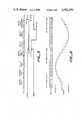
The stimulating waveform must meet three safety requirements: charge balance, current limiting, and charge limiting. FIG. 1 illustrates two of these requirements as achieved in the prior art, FIG. 1A, and as achieved in the present invention, FIG. 1B. The waveforms are charge balanced; i.e., they are biphasic current pulses with equal areas enclosed under both phases. This is necessary because a net DC charge would promote bone growth that could destroy the neural tissue with which the stimulator is interfacing, rendering the implant useless. Also, a charge imbalanced waveform causes electrolysis at the surface of the implanted electrodes. Electrolysis ejects material from the electrode, and can lower the electrode lifetime from years to weeks. The stimulator must therefore recover all the charge delivered to an electrode to prevent neural damage and to insure an adequate implant lifetime.
The stimulators known in the prior art delivered many different types of waveforms, an example of which is shown in FIG. 1A. These stimulators metered the charge delivered by controlling the voltage on a capacitor that discharged into an electrode, an approach that controls charge but not current.
It is an objective of the present invention to provide a transmitter that controls both charge and current flow to the auditory nerves. There is evidence that high current densities can cause neural damage; the peak current of the capacitive discharge scheme combined with the electrode surface area has a current density in this damaging range.
Further, platinum electrodes which are those most commonly used and best adapted for implanting can only support a limited charge density before losing material, at or below 400 nC/cm2. Therefore, it is an objective of the present invention to limit the charge density below this figure.
In summary, the safety requirements of the stimulating waveform must enforce charge balancing, charge limiting and current limiting to prevent possible neural damage.
Referring next to FIG. 2, FIGS. 2A and 2B show the waveform formats which were available with prior art stimulators. It is an objective of the present invention to provide the waveforms shown in FIGS. 2C, 2D and 2E, i.e., a quantized analog, a bipolar pulsatile (two rectangular waveforms that are 180° out of phase), and a monopolar pulsatile (rectangular) waveform.
Known prior art implantable stimulators fell into separate categories; it is an objective of the present invention to provide all three forms of stimulation.
Further, an adequate stimulator should have multiple separate stimulating outputs, possibly eight or more.
Another objective of the present invention to provide independent multi-channel operation, an ability lacking in many known stimulators. This is necessary because a successful stimulation algorithm will most likely require multiple independent channels to independently charge different auditory nerves.
Another objective of the present invention is to provide a system wherein the resolving power exceeds that of the auditory system. Early loudness difference tests showed that a subject could conclusively resolve down to 1.5 nC or charge difference between two stimulations. This charge increment combined with the 250 microamp maximum current means that the minimum timing increment for pulsatile stimulation should be about two microseconds. It is an objective of the present invention to provide an incremental timing resolution down to or below 2 microseconds.
Yet another objective of the present invention is to provide a system that is small, portable, and sufficiently efficient to operate for a full day on a set of transistor radio batteries so that it is convenient to use in a practical sense.
These and other objectives of the present invention are provided by the combination of a transmitter and implantable receiver wherein data is conveyed from transmitter to receiver utilizing a data format in which each channel to be stimulated is adapted to convey information in monopolar, bipolar or analog form.
The data format includes two types of code words: transition words in which one bit is assigned to each channel and can be used to create monopolar pulsatile or bipolar pulsatile waveforms; and amplitude words which can create analog waveforms one channel at a time.
An essential element of the output system is a current source digital to analog converter which responds to the code words to form the appropriate output on each channel. Each output is composed of a set of eight current sources, four with one polarity of current and the other four with the opposite polarity of current. In each group of four, the current sources are binarily related, I, 2I, 4I and 8I. In this arrangement each channel can supply 16 amplitudes times two polarities of current; meaning 32 current levels. This channel is simply a 5-bit digit to analog converter.
The output circuitry contains charge balance switches, something not normally seen in D-to-A converters. These switches are designed to recover residual charge when the current sources are off. They are also designed to current limit during charge recovery if the excess charge is too great so that they do not cause neural damage.
Each channel charge balances (will not pass DC current or charge) and charge limits to prevent electrode damage and bone growth. The charge balancing is performed by the charge balancing switches and by the blocking capacitor. The charge limiting is performed by the blocking capacitor only.
The charge level on each channel is defined using a switch network ladder which combines a plurality of parallel connected switches; closure of each switch doubles the current level handed off from the previous switch.
A number of other advantages of the present invention and features thereof will become apparent from the following detailed description which is given with reference to the following figures:
FIG. 1 illustrates the required properties of the stimulating waveform;
FIG. 2 illustrates examples of desired stimulating waveform;
FIG. 3 illustrates the data word format used to convey data from transmitter to receiver;
FIG. 4 is an illustration which shows schematically the implanted electronics of the auditory prosthesis;
FIGS. 5 and 6 are examples of waveforms which can be created using the subject system;
FIG. 7 shows the voltage regulators and FM demodulator which are coupled to the receiver portion of the stagger tuned coupling system;
FIGS. 8A and 8B show details of the logic chip and the timing to control the logic chip which detects and partially decodes the transmitted data;
FIGS. 9A and 9B show in simplified form and in detail the current source chip which responds to the outputs of the logic chip to provide the current signals over the electrodes to stimulate the auditory nerves.
The coding scheme used to control the implanted system will first be described with reference to FIG. 3. The three primary goals in designing this code are:
One, to account for failure mechanisms and limit their potential effects. This goal protects the subject from incorrect stimulation. It also prevents premature failure of the electrodes, and undue damage to the neural tissue.
Two, to minimize the number of bits needed to create a waveform, while maintaining the ability of producing a near arbitrary wave-shape. This goal reduces the chances of timing conflicts between closely spaced actions, lowers the minimum duration of an action, and expands the flexibility of the stimulator.
Three, to render the data less sensitive to component tolerance and drift. This goal increases the reproducibility and longevity of the implant.
The External Timing Control (ETC) Code is composed of the two words shown in FIG. 3, the "Transition Word" and the "Amplitude Word." Each word is eleven bits long and begins with a start bit. The data is sent on a serial bit stream with floating word frames, so the start bit indicates the beginning of a word. The parity bit checks for an odd number of bit errors in a word. The ID bit distinguishes between an "Amplitude Word" and a "Transition Word." The remaining eight bits contain state commands for the "Transition Word" and current level and address commands for the "Amplitude Word."
The "Transition Word" is intended to increase the flexibility of the system when used as a pulsatile stimulator, by addressing all eight channels of the multi-electrode stimulus array (FIG. 4) simultaneously. A pulsatile output has three possible states, both directions of current plus charge balancing. (Charge balancing means shorting the electrode to body ground, thereby recovering the residual charge left on it.) If, in a "Transition Word," a "one" appears in a given output's bit position, then that output cycles to its next state. If instead a "zero" appears, then that output holds its present state. All eight channels are represented by the last eight bits in the transition word, meaning that the system can simultaneously access them. If two outputs are programmed with opposite polarities of current, then switching them in unison creates a bipolar stimulation. With the "Transition Word" the stimulator can produce synchronized or staggered pulses, and it can act as a one to eight channel monopolar stimulator, or a one to four channel bipolar stimulator, or any mixture of the two types.
The "Amplitude Word" selects the pulsatile state sequence of a given channel. It is also used to create the arbitrary wave-shapes of an analog stimulator. This word is a standard Analog to Digital bit sequence. It has three bits to individually address the eight channels, four bits to adjust the current magnitude, plus one more bit to set the current polarity. The magnitude bits set the peak current of the pulsatile waveforms, while the polarity bit selects one of the two possible pulsatile sequences available for each channel: "sourcing current sinking current charge balancing," or "sinking current sourcing current charge balancing." The polarity bit coupled with the "Transition Word" determines whether a pair of channels deliver monopolar or bipolar stimuli (two synchronized channels with different state sequences can act as a bipolar pair). So the "Amplitude Word" selects the class of stimuli that a channel delivers.
The "Amplitude Word" is also capable of creating an arbitrary current wave-shape. Once the channels are activated by the "Transition Word" (switched from charge balancing to a current supplying state), the "Amplitude Word" can program 16 magnitudes and two polarities for each channel, creating a quantized analog approximation of the desired signal. At a one megabit per second data rate, the Nyquist sampling frequency for each of eight independent channels is 11,364 KHz, which means the maximum frequency that a channel could pass without aliasing a 5682 Hz, well above the 3 KHz cutoff frequency of a telephone channel (telephone quality bandwidth is generally considered necessary for adequate speech comprehension, without assuming a model for the speech production or decoding mechanism). So, under the worst case conditions, where all eight channels are operating as analog outputs, this code can still provide eight independent channels of quantized analog, each with telephone quality bandwidth.
Summarizing, the "Transition Word" is optimized for creating pulsatile stimulation. It can simultaneously address all eight channels and, with the help of the polarity bit in the "Amplitude Word," it can provide monopolar or bipolar stimulation. The "Amplitude Word" sets the current levels and state sequence of each channel. It can also create a quantized analog waveform on each channel. So this code provides all three classes of stimulation, monopolar pulsatile, bipolar pulsatile, and quantized analog.
This is an open loop system; information is sent in, but nothing is sent back out. The effects of errors are limited in two ways. First, the system is periodically resynchronized. Since the system is open loop, the external electronics must force the implanted electronics into a known state, after some time interval, to ensure that the two sub-systems agree. Synchronization is accomplished by transmitting an unused bit sequence of the "Transition Word." It is a "Transition Word" with no transitions. This special case is interpreted as a "Master Reset" that programs all the current sources to zero current, forces all the outputs into their charge balanced state, and clears all error conditions.
The periodic resetting is a "catch-all" approach for protection against unstoppable errors. One example of an unstoppable error is a coding mistake in the instructions sent to the package. These generally come from software bugs encountered while implementing a new algorithm or a new hardware system. This could deliver too much charge to an electrode, leave a current source "on," or deliver a charge imbalanced waveform. The implant volunteer requires protection from these potentially catastrophic mistakes. The ETC Code limits the effects of these mistakes by requiring at least one "Master Reset" every 5 ms to keep the package operational. Otherwise, the unit enters an error state, which is described later. This restriction bounds the effects of an error (detected or otherwise) to one 5 ms interval. It also initiates at least one attempt every 5 ms to charge balance all the electrodes correcting for any missed errors.
Second, upon detecting an error, the system programs all the current sources to zero, forces all the outputs into their charge balanced states, and enters an error state. The effect is similar to a "Master Reset" except that the package ignores all incoming commands. Only a "Master Reset" can clear the error state. By shutting down until the next resynchronization instead of continuing operation, the system has stopped an error from propagating into many errors. For instance, one biphasic pulse requires three "Transition Words." If one of those words contained an error that switched "on" the wrong channel, or did not switch the correct one, then an output would not return to its charge balanced state. Instead, it would continue supplying current, causing a charge imbalance on an electrode, and creating a potential source of failure. Here, one bit error has lost the synchronization between the outside and inside worlds, and later "Transition Words" are performing unintended tasks. So shutting down after detecting an error limits the effect of an error and prevents one error from growing into many.
There are three conditions that force the package into an error state: too long an interval between "Master Resets," parity errors, and a lost data stream. The reasons for detecting the "Master Reset" interval are already covered. The parity errors occur when the coils of the inductive link are too widely separated. Depending on the receiver design, the zero bits become ones, or the one bits become zeros. In either case, the data words are interpreted as all one type of bit. The words contain an odd number of bits, so the ETC Code forces even parity (at least one opposite bit in each word) to detect this condition.
FIG. 5 illustrates how to use the ETC Code to create a pulsatile waveform and the results of a detected error. The top line is the control word bit stream sent into the package. The next two lines are the current outputs of two channels of the stimulator. A pulsatile waveform generally relies heavily on "Transition Words" as shown in this example. The "Master Reset" is first sent into the package to clear any error conditions and to synchronize the system. Next, two "Amplitude Words" set the polarity and magnitude that the current sources ofchannel 1 andchannel 5 deliver when they are turned "on." Next, a "Transition Word" switches these two channels out of their charge balanced state, simultaneously. The switching occurs one bit period after the word is received. Then two more "Transition Words" complete the state sequence forchannel 5. Finally, another "Transition Word" attempts tocycle channel 1 to its next state. But the word contains a parity error that force all the outputs into their charge balancing state to recover any residual charge, and the package halts in an error state, where it stays until another "Master Reset" is sent. So once the magnitude and polarity of a pulsatile waveform are programmed, "Transition Words" control the timing of the current source switching. Since they can switch up to eight channels at a time, few timing conflicts should arise.
FIG. 6 is an example of the ETC Code producing a quantized analog wave-shape. While the pulsatile example relied primarily on "Transition Words," creating arbitrary waveforms usually requires using the "Amplitude Word." The top line of the figure is the input data word stream and the lower line represents the current output of one channel. Again, a "Master Reset" is sent to clear and synchronize the package. Then a "Transition Word" is sent to turn the current source "on." No current is delivered because the "Master Reset" programmed the outputs to zero current. Now "Amplitude Words" are sent to construct a waveform in a typical D to A pattern. Finally, another "Master Reset" is sent to keep the system from timing out (remember, no more than 5 ms are allowed between "Master Reset" words) and to recover residual charge on the electrodes. So the ETC Code can create analog as well as pulsatile waveforms.
The ETC Code was designed to reduce the number of bits needed to create a signal (or event). By pruning the unnecessary information from the data, the word length is reduced, allowing the transmission of more instructions per unit of time.
To achieve this goal, the ETC Code transmits the state information in the control words and the timing information in the temporal position of each word. In other words, when an action is required, a word specifying the state of one or more currents is sent, and the action occurs one bit cycle after the word is received. Thus, bits containing temporal information (pulse width, pulse position, pulse period, etc.) are unnecessary.
The ETC Code also takes advantage of advance knowledge about the pulsatile wave-shapes (monopolar and bipolar) to further reduce the number of bits needed to create these waveforms. Each output channel has three possible pulsatile states, "sourcing current," "sinking current," and "balancing charge." Defining three states per channel for an eight channel system normally requires 16 bits. But the need for charge balancing generally locks the outputs into the sequence of "current; opposite polarity current; charge balancing." By specifying a state transition instead of an absolute state, only one bit per channel is needed; cutting the number of data bits from 16 to 8. In other words, the control word does not tell a channel explicitly what job to do. Instead, it tells the channel to stop whatever it is doing and move on to its next job, without stating what the next job is.
Summarizing, bits containing the timing and the absolute state information are unnecessary for this code, allowing a significant increase in the number of instructions per unit of time.
The bit stream is encoded using pulse-duration-modulation. In this case, a long pulse is a "one" and short pulse is a "zero." PDM was chosen because the leading edge contains the timing (synchronizing) information, and the simple circuit that decodes it can also use this information to generate the internal clock. By combining the detector and clock into one circuit, the system gains temporal flexibility, reduces its sensitivity to component variations, and saves power.
Since the clock period is set by the period of the incoming bits, the user can change the temporal resolution of the package without altering the implanted electronics. In fact, the package can track any data rate slower than its maximum; even to DC (although it flags a bit stream "time out" error when the bit period exceeds 22 μs). This approach has added the capability of modulating the temporal position of a waveform, and eliminates the requirement of locking a waveform's transitions to a fixed clock period, such as 1 μs/bit.
Another advantage of this approach is that it eliminates the problem of synchronizing two clocks, one internal and one external. Though normally not a major problem, it can become serious as components age and time constants change. The package is intended to operate for 10 years, long enough for these problems to surface. By maxing the timing accuracy dependent only on the external electronics, the system should have a dependable clock period for the full 10 years.
Finally, if high clock speeds are unnecessary, then slowing the clock rate of the system lowers its power consumption. This ability may open a wider range of applications for this stimulator, such as muscle control, or pain suppression.
The choice of pulse-duration-modulation simplifies the detector/clock circuitry, adds the capability of temporal modulation, desensitizes the system to component aging and drift, and allows a reduction in the power consumption of the system that may open new applications.
The coupling from the transmitter for this data (which may be of any well-known design) to the implanted receiver is disclosed in the incorporated patent application of Galbraith, et al.
The stagger-tuned link produced a fairly stable output voltage from which to create a regulated voltage supply. Ideally, an efficient voltage regulator would operate with a small voltage dropped across it, so that it consumes little power while sourcing large currents. It should also burn a negligible amount of quiescent current for its own operation. The regulators used in the stimulator are close to this ideal. Their circuit diagrams are shown in FIG. 7. These voltage regulators function down to one saturated bipolar transistor drop (0.3 volts) across them at full load current; the quiescent current consumption for both regulators is about 0.25 mA, less than 10 percent of the total stimulator current (3.3 mA maximum).
These regulators are capable of both sourcing and sinking current. This capability provides general protection for the implanted electronics if excessive voltages occur from design oversights. It was added to reduce or eliminate the potential effects of any design oversights.
This section describes the circuitry that converts the information sent by the ETC Code into stimulation patterns on the electrodes is disclosed with reference to FIGS. 8, 9 and 10. It covers, in detail, the implementation of the safety requirements. It also provides examples showing the achievement of the principal design goals; producing all three classes of stimulation for flexibility, arbitrary wave-shape for experimental needs, and independent multi-channel operation.
The logic chip of FIG. 8 performs the decoding of the PDM data stream and most of the ECT Code. The circuit diagram is shown in FIG. 8A and an example timing diagram is shown in FIG. 8B. The PDM decoding is done simply by a D-flip-flop and a one-shot. The rising edge of the PDM signal fires the one-shot and the data is detected on the falling edge by the flip-flop. The one-shot also acts as the clock so that the internal clock tracks the data rate, allowing temporal modulation of the switching information. This simple circuit not only performs detection and clock generation; it also eliminates the need for an accurate internal timing reference since it derives this information from the outside world.
The rest of the chip contains the state machines for all eight channels, the logic to decode most of the ETC coded bit stream, and implements most of the protection conditions of the ETC Code. This chip explicitly decodes the transition word that drives the output state machines and that carries the Master Reset. This chip performs the "power on reset," parity checking, and lost bit stream detection. The interface between it and the current source chip performs the Master Reset time-out detection.
This design is fairly conservative to improve the chances of successful operation. As examples, the circuitry is fully clocked to avoid race conditions. It uses cellular elements to minimize the layout mistakes. The clocking one-shot is insensitive to the duration of a bit so that different data rates will not affect the detection period. The transistors are operated nearly two orders of magnitude below their maximum switching frequency so that the circuit can tolerate a large variation in the fabrication process.
To reduce the power consumption of the system, the logic chip operates at a lower power supply voltage than the current source chip. The logic chip only needs 5 volts of the 13-volt supply to function. Since the power drawn by a CMOS circuit tends to increase with the square of the voltage, the lower supply cuts the power consumption significantly.
To further reduce the power used, the control lines connecting the logic chip to the current source chip are only active when sending information. The current source chip must level shift all the incoming signals from the logic chip and level shifters consume power. So the conservative design ensures safe operation and saves power.
The logic is implemented using a CMOS gate array (SPI 7005B) from Semi Processes Incorporated. The array contains roughly 5000 transistors of which about 3000 are used to implement the system logic using known gate array connection techniques.
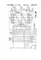
The current source chip of FIG. 9 performs the final decoding of the amplitude word and provides the coding to current interface to the electrodes. It, along with a few external components, also ensures the safety of the implant by limiting the current and charge, and by providing charge balancing.
FIG. 9A shows a conceptual diagram for one channel. There are eight current sources per channel. They are divided into two groups of binarily related values (I, 2I, 4I and 8I), giving 16 magnitudes and two polarities. The switches So through S3 set the magnitude of the current under control of the Amplitude Word. The switches Sin and Sout determine the polarity and are primarily controlled by the transition word. Each channel is capable of providing a pulsatile or quantized analog output depending on the switching sequence of these pass gates. For example, to produce a monophasic pulse, simply program the current sources (say turn on S1 and S2), then alternately switch Sout on and Sin on.
The blocking capacitor CB is an external component that is probably the most important safety element of each stimulating channel. It stops DC current from passing into the electrode. DC current would eventually destroy the electrode, possibly damage the nerves, and promote bone growth. The capacitor CB also acts as a charge limiter. Excessive charge (about 400 nC/phase in this case) causes the electrodes to break down. This capacitor limits the worst case charge to about 300 nC/phase. Finally, since this capacitor is a high reliability pace maker part and since it is the last component between the stimulator and the electrodes, it limits the effects of failures in the electronics leading to the electrodes (such as limiting the output charge of a current source that is stuck "on"). So this capacitor limits the charge, blocks the DC current, and protects against component failures; all of which should prevent damage to the electrodes and nerves.
Notice that Sin and Sout have two complementary switches that can short the output to ground. These switches and the blocking capacitor ensure the charge balancing. Once the current sources have completed delivering current, any residual charge left on an electrode appears as a voltage across the blocking capacitor. By shorting the output, that charge is recovered.
The current and charge limits of this system are not locked by the integrated circuits. Instead, they are programmed by components external to the chip (but still inside the implanted package). This arrangement allows for adjusting the stimulator to new electrodes or new uses. For example, a larger electrode surface area could support higher currents and more charge than the present system is set for. The maximum output charge is determined by the power supply voltage and the size of the blocking capacitor, so a new blocking capacitor sets a new maximum output charge. To understand how the maximum current is adjusted, look at the circuit diagram for the current source chip shown in FIG. 9B. Notice that the reference current for all the current sources is set by one external resistor RI. A new resistor sets a new current peak. Therefore, even though the chips are static, the stimulating characteristics of the system are programmable (at least until the package is sealed) and can match the needs of future implants.
In summary, the system is conservatively designed in an effort to promote reliability. It provides safety and a long electrode lifetime by limiting the current and charge, by blocking any DC current, and by charge balancing. Its current and charge limits are reprogrammable allowing it to adapt to future needs. It is flexible, capable of producing monopolar, bipolar, and analog outputs with few limitations in each class. It can create nonstandard waveforms for research needs, and it provides eight independent channels of stimuli. In summary, it has met its primary goals of safety and flexibility.
Claims (9)
1. A neural stimulator comprising a transmitter, an implantable receiver and means for coupling the output of said transmitter to said receiver, said receiver including a plurality of output channels to the nerves of the wearer, said receiver including means for simultaneously addressing each of said channels in monopolar or bipolar mode, or alternatively in analog mode to stimulate said nerves.
2. A stimulator as claimed in 1 wherein said receiver includes a current source device coupled to each of said channels, said current source device comprising a switch network, the number of closed switches selectively defining the charge and current envelope on any channel.
3. A stimulator as claimed in claim 2 further comprising a charge balancing switch cooperating with each of said current source devices and blocking capacitors for eliminating charge imbalance into the electrode channels.
4. A stimulator as claimed in 1 wherein said addressing means further comprise means for defining a quantized analog current waveform on any of said channels.
5. A stimulator as claimed in claim 1 further comprising a multi-electrode stimulus array connected to the output channels of the stimulator.
6. A stimulator as claimed in claim 5 including means for establishing transition words for defining a binary state on each of said channels, and means for creating amplitude words for defining an analog signal on any of said channels.
7. A stimulator as claimed in claim 5 wherein said means for establishing a transition word simultaneously address all of said plurality of channels.
8. A stimulator as claimed in claim 7 wherein said means for establishing a transition word comprise means for transmitting an unused bit sequence for synchronizing all of said channels.
9. A stimulator as claimed in claim 7 wherein said means for establishing a transition word cooperate with a polarity bit from the means for establishing an amplitude word to provide monopolar or bipolar stimulation on each of said channels.
Priority Applications (8)
| Application Number | Priority Date | Filing Date | Title |
|---|---|---|---|
| US06/719,231US4592359A (en) | 1985-04-02 | 1985-04-02 | Multi-channel implantable neural stimulator |
| DE8686302273TDE3685510D1 (en) | 1985-04-02 | 1986-03-26 | IMPLANTABLE MULTI-CHANNEL NERVOUS STIMULATOR. |
| EP86302273AEP0198618B1 (en) | 1985-04-02 | 1986-03-26 | A mult-channel implantable neural stimulator |
| AU55350/86AAU5535086A (en) | 1985-04-02 | 1986-03-27 | Multi-channel implantable neural stimulator |
| CN86103049.4ACN1005897B (en) | 1985-04-02 | 1986-03-29 | Multi-channel implantable neural stimulator |
| CA000505524ACA1284185C (en) | 1985-04-02 | 1986-04-01 | Multi-channel implantable neural stimulator |
| JP61076407AJPS61293475A (en) | 1985-04-02 | 1986-04-02 | Multiple channel embedding type nerve stimulation apparatus |
| AU54985/90AAU5498590A (en) | 1985-04-02 | 1990-05-14 | A multi-channel implantable neural stimulator |
Applications Claiming Priority (1)
| Application Number | Priority Date | Filing Date | Title |
|---|---|---|---|
| US06/719,231US4592359A (en) | 1985-04-02 | 1985-04-02 | Multi-channel implantable neural stimulator |
Publications (1)
| Publication Number | Publication Date |
|---|---|
| US4592359Atrue US4592359A (en) | 1986-06-03 |
Family
ID=24889281
Family Applications (1)
| Application Number | Title | Priority Date | Filing Date |
|---|---|---|---|
| US06/719,231Expired - Fee RelatedUS4592359A (en) | 1985-04-02 | 1985-04-02 | Multi-channel implantable neural stimulator |
Country Status (7)
| Country | Link |
|---|---|
| US (1) | US4592359A (en) |
| EP (1) | EP0198618B1 (en) |
| JP (1) | JPS61293475A (en) |
| CN (1) | CN1005897B (en) |
| AU (2) | AU5535086A (en) |
| CA (1) | CA1284185C (en) |
| DE (1) | DE3685510D1 (en) |
Cited By (149)
| Publication number | Priority date | Publication date | Assignee | Title |
|---|---|---|---|---|
| WO1989002694A1 (en)* | 1987-09-11 | 1989-03-23 | Resound Corporation | Method and apparatus for treating hearing deficiencies |
| US4890618A (en)* | 1985-09-12 | 1990-01-02 | Bertin & Cie | Nerve-stimulating device for auditory prosthesis |
| US4892108A (en)* | 1987-07-23 | 1990-01-09 | The Regents Of The University Of Michigan | Multi-channel extracochlear implant |
| US4932405A (en)* | 1986-08-08 | 1990-06-12 | Antwerp Bionic Systems N.V. | System of stimulating at least one nerve and/or muscle fibre |
| US4934368A (en)* | 1988-01-21 | 1990-06-19 | Myo/Kinetics Systems, Inc. | Multi-electrode neurological stimulation apparatus |
| US4944301A (en)* | 1988-06-16 | 1990-07-31 | Cochlear Corporation | Method for determining absolute current density through an implanted electrode |
| US4947844A (en)* | 1984-09-07 | 1990-08-14 | The University Of Melbourne | Receiver/stimulator for hearing prosthesis |
| WO1991003913A1 (en)* | 1989-09-08 | 1991-03-21 | Cochlear Pty. Limited | Multi-peak speech processor |
| US5038781A (en)* | 1988-01-21 | 1991-08-13 | Hassan Hamedi | Multi-electrode neurological stimulation apparatus |
| US5069210A (en)* | 1989-04-17 | 1991-12-03 | Jeutter Dean C | Cochlear implant employing frequency-division multiplexing and frequency modulation |
| US5215085A (en)* | 1988-06-29 | 1993-06-01 | Erwin Hochmair | Method and apparatus for electrical stimulation of the auditory nerve |
| US5217009A (en)* | 1991-07-10 | 1993-06-08 | Kronberg James W | Compact biomedical pulsed signal generator for bone tissue stimulation |
| US5271397A (en)* | 1989-09-08 | 1993-12-21 | Cochlear Pty. Ltd. | Multi-peak speech processor |
| US5522865A (en)* | 1989-09-22 | 1996-06-04 | Alfred E. Mann Foundation For Scientific Research | Voltage/current control system for a human tissue stimulator |
| US5531774A (en)* | 1989-09-22 | 1996-07-02 | Alfred E. Mann Foundation For Scientific Research | Multichannel implantable cochlear stimulator having programmable bipolar, monopolar or multipolar electrode configurations |
| US5569307A (en)* | 1989-09-22 | 1996-10-29 | Alfred E. Mann Foundation For Scientific Research | Implantable cochlear stimulator having backtelemetry handshake signal |
| US5584870A (en)* | 1995-03-09 | 1996-12-17 | Cochlear Ltd. | Implant ESD protection network |
| US5601608A (en)* | 1995-02-02 | 1997-02-11 | Pacesetter, Inc. | Methods and apparatus for applying charge-balanced antiarrhythmia shocks |
| US5603726A (en)* | 1989-09-22 | 1997-02-18 | Alfred E. Mann Foundation For Scientific Research | Multichannel cochlear implant system including wearable speech processor |
| US5626629A (en)* | 1995-05-31 | 1997-05-06 | Advanced Bionics Corporation | Programming of a speech processor for an implantable cochlear stimulator |
| WO1997033647A1 (en)* | 1996-03-13 | 1997-09-18 | Med-El Elektromedizinische Geräte GmbH | Device and method for implants in ossified cochleas |
| US5755747A (en)* | 1995-12-19 | 1998-05-26 | Daly; Christopher | Cochlear implant system with soft turn on electrodes |
| US5876425A (en)* | 1989-09-22 | 1999-03-02 | Advanced Bionics Corporation | Power control loop for implantable tissue stimulator |
| US5938691A (en)* | 1989-09-22 | 1999-08-17 | Alfred E. Mann Foundation | Multichannel implantable cochlear stimulator |
| EP0965969A1 (en)* | 1998-06-18 | 1999-12-22 | Gavriil Mikhailovich Fingerov | The method of conveying information to the nervous system of a person |
| US6073050A (en)* | 1998-11-10 | 2000-06-06 | Advanced Bionics Corporation | Efficient integrated RF telemetry transmitter for use with implantable device |
| US6181969B1 (en) | 1998-06-26 | 2001-01-30 | Advanced Bionics Corporation | Programmable current output stimulus stage for implantable device |
| US6272382B1 (en) | 1998-07-31 | 2001-08-07 | Advanced Bionics Corporation | Fully implantable cochlear implant system |
| US6289247B1 (en) | 1998-06-02 | 2001-09-11 | Advanced Bionics Corporation | Strategy selector for multichannel cochlear prosthesis |
| US6354299B1 (en) | 1997-10-27 | 2002-03-12 | Neuropace, Inc. | Implantable device for patient communication |
| US6415185B1 (en) | 1998-09-04 | 2002-07-02 | Advanced Bionics Corporation | Objective programming and operation of a Cochlear implant based on measured evoked potentials that precede the stapedius reflex |
| US6415186B1 (en) | 2000-01-14 | 2002-07-02 | Advanced Bionics Corporation | Active feed forward power control loop |
| US6458157B1 (en)* | 1997-08-04 | 2002-10-01 | Suaning Gregg Joergen | Retinal stimulator |
| US6463328B1 (en) | 1996-02-02 | 2002-10-08 | Michael Sasha John | Adaptive brain stimulation method and system |
| US6480740B2 (en) | 2000-12-26 | 2002-11-12 | Cardiac Pacemakers, Inc. | Safety pacing in multi-site CRM devices |
| US6493586B1 (en) | 2000-08-30 | 2002-12-10 | Cardiac Pacemakers, Inc. | Site reversion in cardiac rhythm management |
| US6516227B1 (en) | 1999-07-27 | 2003-02-04 | Advanced Bionics Corporation | Rechargeable spinal cord stimulator system |
| US20030036782A1 (en)* | 2001-08-20 | 2003-02-20 | Hartley Lee F. | BioNet for bilateral cochlear implant systems |
| US6535767B1 (en) | 2001-08-21 | 2003-03-18 | James W. Kronberg | Apparatus and method for bioelectric stimulation, healing acceleration and pain relief |
| US6584362B1 (en) | 2000-08-30 | 2003-06-24 | Cardiac Pacemakers, Inc. | Leads for pacing and/or sensing the heart from within the coronary veins |
| US20030135247A1 (en)* | 1999-07-21 | 2003-07-17 | Zierhofer Clemens M. | Multichannel cochlear implant with neural response telemetry |
| US6611717B1 (en)* | 1993-07-01 | 2003-08-26 | The University Of Melbourne | Implant device |
| US6620094B2 (en) | 2001-11-21 | 2003-09-16 | Otologics, Llc | Method and apparatus for audio input to implantable hearing aids |
| US20030204222A1 (en)* | 2002-04-26 | 2003-10-30 | Medtronic, Inc. | Recharge delay for an implantable medical device |
| US20030204224A1 (en)* | 2002-04-26 | 2003-10-30 | Medtronic, Inc. | Programmable waveform pulses for an implantable medical device |
| US20040082985A1 (en)* | 2000-03-31 | 2004-04-29 | Faltys Michael A. | High contact count, sub-miniature, fully implantable cochlear prosthesis |
| US20040267333A1 (en)* | 2003-06-24 | 2004-12-30 | Kronberg James W. | Apparatus and method for bioelectric stimulation, healing acceleration, pain relief, or pathogen devitalization |
| US20050149123A1 (en)* | 1999-10-19 | 2005-07-07 | The Johns Hopkins University | Techniques using heat flow management, stimulation, and signal analysis to treat medical disorders |
| US20050222644A1 (en)* | 2004-03-31 | 2005-10-06 | Cochlear Limited | Pulse burst electrical stimulation of nerve or tissue fibers |
| US7016738B1 (en) | 2002-07-31 | 2006-03-21 | Advanced Bionics Corporation | Digitally controlled RF amplifier with wide dynamic range output |
| US7054691B1 (en) | 2002-01-02 | 2006-05-30 | Advanced Bionics Corporation | Partitioned implantable system |
| US20060149340A1 (en)* | 2002-07-31 | 2006-07-06 | Karunasiri Rankiri T | Systems and methods for providing power to one or more implantable devices |
| US20060212094A1 (en)* | 2004-12-31 | 2006-09-21 | Ludwig Moser | Middle ear multi-channel electrode |
| US7127298B1 (en) | 2002-10-18 | 2006-10-24 | Advanced Bionics Corporation | Switched-matrix output for multi-channel implantable stimulator |
| US20060271118A1 (en)* | 2005-05-25 | 2006-11-30 | Cardiac Pacemakers, Inc. | Implantable neural stimulator with mode switching |
| US20070027405A1 (en)* | 2005-07-29 | 2007-02-01 | Merfeld Daniel M | Mechanical vestibular stimulator |
| US20070027465A1 (en)* | 2005-08-01 | 2007-02-01 | Merfeld Daniel M | Vestibular canal plug |
| US20070060983A1 (en)* | 2005-09-14 | 2007-03-15 | Massachusetts Eye & Ear Infirmary | Optical vestibular stimulator |
| US7225028B2 (en) | 2004-05-28 | 2007-05-29 | Advanced Bionics Corporation | Dual cochlear/vestibular stimulator with control signals derived from motion and speech signals |
| US20070244535A1 (en)* | 2006-04-18 | 2007-10-18 | Cyberonics, Inc. | Heat dissipation for a lead assembly |
| US20070250136A1 (en)* | 2006-03-29 | 2007-10-25 | Karunasiri Rankiri T | Systems and methods of facilitating communication between a first and second device |
| US20070270922A1 (en)* | 2006-05-18 | 2007-11-22 | Clemens Zierhofer | Implanted system with dc free inputs and outputs |
| US20080015641A1 (en)* | 2006-07-12 | 2008-01-17 | Cyberonics, Inc. | Implantable Medical Device Charge Balance Assessment |
| US20080114405A1 (en)* | 2006-11-13 | 2008-05-15 | Palmer Logan P | Methods and systems for removing accumulated charge from one or more electrodes |
| US20080183258A1 (en)* | 2007-01-26 | 2008-07-31 | Inman D Michael | Electrode assembly with fibers for a medical device |
| US20080195179A1 (en)* | 2006-07-17 | 2008-08-14 | Advanced Bionics Corporation | Systems and methods for determining a threshold current level required to evoke a stapedial muscle reflex |
| US20080198947A1 (en)* | 2007-02-15 | 2008-08-21 | Zierhofer Clemens M | Inductive Power and Data Transmission System Based on Class D and Amplitude Shift Keying |
| US20080221644A1 (en)* | 2007-03-09 | 2008-09-11 | Enteromedics, Inc. | Remote monitoring and control of implantable devices |
| US20080269847A1 (en)* | 2004-03-02 | 2008-10-30 | Mikhall Nemenov | Portable laser and process for pain research |
| US20080300656A1 (en)* | 2007-05-31 | 2008-12-04 | Adrianus Donders | Implantable therapy system |
| US20090018616A1 (en)* | 2006-07-17 | 2009-01-15 | Advanced Bionics, Llc | Systems and Methods for Determining a Threshold Current Level Required to Evoke a Stapedial Muscle Reflex |
| US20090043361A1 (en)* | 2007-08-10 | 2009-02-12 | Med-El Elektromedizinische Geraete Gmbh | Pulse Width Adaptation for Inductive Links |
| US20090088827A1 (en)* | 2007-10-02 | 2009-04-02 | Cardiac Pacemakers, Inc | Lead assembly providing sensing or stimulation of spaced-apart myocardial contact areas |
| US7519428B1 (en)* | 2002-06-14 | 2009-04-14 | Advanced Bionics, Llc | Dual-range compliance voltage supply for a multi-channel stimulator |
| US20090112292A1 (en)* | 2007-10-26 | 2009-04-30 | Cyberonics Inc. | Dynamic lead condition detection for an implantable medical device |
| US20090125079A1 (en)* | 2007-10-26 | 2009-05-14 | Cyberonics Inc. | Alternative operation mode for an implantable medical device based upon lead condition |
| US20090132010A1 (en)* | 2007-11-19 | 2009-05-21 | Kronberg James W | System and method for generating complex bioelectric stimulation signals while conserving power |
| US20090157151A1 (en)* | 2007-11-26 | 2009-06-18 | Microtransponder, Inc. | Implantable Transponder Pulse Stimulation Systems and Methods |
| US20090157145A1 (en)* | 2007-11-26 | 2009-06-18 | Lawrence Cauller | Transfer Coil Architecture |
| US20090198293A1 (en)* | 2003-12-19 | 2009-08-06 | Lawrence Cauller | Microtransponder Array for Implant |
| US20090259140A1 (en)* | 2006-10-13 | 2009-10-15 | Buchman Craig A | Apparatus and methods for acoustically or mechanically stimulating a cochlea and intracochlear recording of mechanically or acoustically evoked auditory potentials in the cochlea |
| US20100004717A1 (en)* | 2008-07-02 | 2010-01-07 | Microtransponder Inc. | Timing Control for Paired Plasticity |
| US7647120B2 (en) | 2004-05-28 | 2010-01-12 | John Hopkins School Of Medicine | Dual cochlear/vestibular stimulator with control signals derived from motion and speech signals |
| US20100022908A1 (en)* | 2003-12-19 | 2010-01-28 | Board Of Regents, The University Of Texas System | System and Method for Interfacing Cellular Matter with a Machine |
| US20100046779A1 (en)* | 2003-05-08 | 2010-02-25 | Crawford Scott A | Modular speech processor headpiece |
| US20100046778A1 (en)* | 2003-05-08 | 2010-02-25 | Crawford Scott A | Integrated cochlear implant headpiece |
| US7676372B1 (en) | 1999-02-16 | 2010-03-09 | Yugen Kaisha Gm&M | Prosthetic hearing device that transforms a detected speech into a speech of a speech form assistive in understanding the semantic meaning in the detected speech |
| US20100069994A1 (en)* | 2007-06-25 | 2010-03-18 | Microtransponder, Inc. | Methods of inducing paresthesia using wireless neurostimulation |
| US20100121399A1 (en)* | 2005-04-05 | 2010-05-13 | Mccabe Aaron | Closed loop neural stimulation synchronized to cardiac cycles |
| US20100137940A1 (en)* | 1997-07-21 | 2010-06-03 | Levin Bruce H | Method for Directed Intranasal Administration of a Composition |
| WO2010085596A1 (en)* | 2009-01-23 | 2010-07-29 | Med-El Elektromedizinische Geraete Gmbh | Stimulation channel conditioning |
| US7769467B1 (en) | 2007-01-31 | 2010-08-03 | Advanced Bionics, Llc | Level-dependent stimulation methods and systems |
| US20100198300A1 (en)* | 2009-02-05 | 2010-08-05 | Cochlear Limited | Stimulus timing for a stimulating medical device |
| US20100192374A1 (en)* | 2006-07-26 | 2010-08-05 | Cyberonics, Inc. | Multi-Electrode Assembly for an Implantable Medical Device |
| US7794499B2 (en) | 2004-06-08 | 2010-09-14 | Theken Disc, L.L.C. | Prosthetic intervertebral spinal disc with integral microprocessor |
| US20100256708A1 (en)* | 2009-04-03 | 2010-10-07 | Thornton Arnold W | Implantable device with heat storage |
| US7818061B1 (en) | 2006-10-13 | 2010-10-19 | Advanced Bionics, Llc | Systems and methods for detecting an error associated with an implantable device |
| WO2011014909A1 (en)* | 2009-08-03 | 2011-02-10 | Cochlear Limited | Implant stimulation device |
| WO2011044616A1 (en)* | 2009-10-12 | 2011-04-21 | Newsouth Innovations Pty Limited | Method of power and data transfer in implantable electronic devices |
| US20110093043A1 (en)* | 2009-10-21 | 2011-04-21 | Medtronic, Inc. | Programming techniques for stimulation with utilization of case electrode |
| US20110093042A1 (en)* | 2009-10-21 | 2011-04-21 | Medtronic, Inc. | Stimulation with utilization of case electrode |
| US20110125214A1 (en)* | 2009-11-25 | 2011-05-26 | Medtronic, Inc. | Medical electrical stimulation with external simulated case electrode |
| US7983758B1 (en) | 2005-03-14 | 2011-07-19 | Advanced Bionics, Llc | Sound processing and stimulation systems and methods for use with cochlear implant devices |
| US8027734B1 (en) | 2007-07-13 | 2011-09-27 | Advanced Bionics, Llc | Methods and systems of optimizing stimulation current applied to a cochlear implant patient |
| US8107661B1 (en) | 2003-05-08 | 2012-01-31 | Advanced Bionics, Llc | Listening device cap |
| US8165689B1 (en) | 2008-04-09 | 2012-04-24 | Advanced Bionics, Llc | Methods and systems of compensating for a disabled electrode |
| US8265766B1 (en) | 2008-12-23 | 2012-09-11 | Advanced Bionics, Llc | Methods and systems of automatically detecting an impedance of one or more electrodes in a cochlear implant system |
| US8364274B1 (en) | 2006-12-29 | 2013-01-29 | Advanced Bionics, Llc | Systems and methods for detecting one or more central auditory potentials |
| US8412336B2 (en) | 2008-12-29 | 2013-04-02 | Autonomic Technologies, Inc. | Integrated delivery and visualization tool for a neuromodulation system |
| US8423147B2 (en) | 2009-04-22 | 2013-04-16 | Nevro Corporation | Devices for controlling high frequency spinal cord modulation for inhibiting pain, and associated systems and methods, including simplified controllers |
| US8457757B2 (en) | 2007-11-26 | 2013-06-04 | Micro Transponder, Inc. | Implantable transponder systems and methods |
| US8473062B2 (en) | 2008-05-01 | 2013-06-25 | Autonomic Technologies, Inc. | Method and device for the treatment of headache |
| US8478428B2 (en) | 2010-04-23 | 2013-07-02 | Cyberonics, Inc. | Helical electrode for nerve stimulation |
| US8494641B2 (en) | 2009-04-22 | 2013-07-23 | Autonomic Technologies, Inc. | Implantable neurostimulator with integral hermetic electronic enclosure, circuit substrate, monolithic feed-through, lead assembly and anchoring mechanism |
| CN101874913B (en)* | 2009-04-30 | 2013-07-31 | 上海华聆人工耳医疗科技有限公司 | Balanced single-polar component type multi-channel cochlear implant system with detection feedback function |
| WO2013134763A2 (en) | 2012-03-09 | 2013-09-12 | Enteromedics Inc. | Safety features for use in medical devices |
| US8548585B2 (en) | 2009-12-08 | 2013-10-01 | Cardiac Pacemakers, Inc. | Concurrent therapy detection in implantable medical devices |
| US8560080B2 (en) | 2010-06-11 | 2013-10-15 | Medtronic, Inc. | Programming techniques for controlling rate of change of electrical stimulation therapy |
| US20140100643A1 (en)* | 2005-07-08 | 2014-04-10 | Boston Scientific Neuromodulation Corporation | Current Output Architecture for an Implantable Stimulator Device |
| US20140107752A1 (en)* | 2005-07-08 | 2014-04-17 | Boston Scientific Neuromodulation Corporation | Current Generation Architecture for an Implantable Stimulator Device Having Coarse and Fine Current Control |
| US8751006B2 (en) | 2008-12-23 | 2014-06-10 | Advanced Bionics Ag | Channel-specific adjustment of sound processing strategies based on electrode impedance |
| US8805494B2 (en) | 2005-05-10 | 2014-08-12 | Cardiac Pacemakers, Inc. | System and method to deliver therapy in presence of another therapy |
| WO2014130865A3 (en)* | 2013-02-22 | 2014-10-16 | Boston Scientific Neuromodulation Corporation | Neurostimulation system having increased flexibility for creating complex pulse trains |
| US8903502B2 (en) | 2012-05-21 | 2014-12-02 | Micron Devices Llc | Methods and devices for modulating excitable tissue of the exiting spinal nerves |
| US8996123B2 (en) | 2009-10-21 | 2015-03-31 | Medtronic, Inc. | Managing electrical stimulation therapy based on variable electrode combinations |
| WO2015099682A1 (en)* | 2013-12-23 | 2015-07-02 | Advanced Bionics Ag | Radio frequency ("rf") power level management systems and methods for use in a cochlear implant system |
| US9199089B2 (en) | 2011-01-28 | 2015-12-01 | Micron Devices Llc | Remote control of power or polarity selection for a neural stimulator |
| US9220897B2 (en) | 2011-04-04 | 2015-12-29 | Micron Devices Llc | Implantable lead |
| US9242103B2 (en) | 2011-09-15 | 2016-01-26 | Micron Devices Llc | Relay module for implant |
| US9295850B2 (en) | 2012-04-24 | 2016-03-29 | Medtronic, Inc. | Charge-balancing during electrical stimulation |
| US9320908B2 (en) | 2009-01-15 | 2016-04-26 | Autonomic Technologies, Inc. | Approval per use implanted neurostimulator |
| US9320901B2 (en) | 2010-04-28 | 2016-04-26 | Medtronic, Inc. | Stimulation with utilization of non-selected electrode |
| US9409030B2 (en) | 2011-01-28 | 2016-08-09 | Micron Devices Llc | Neural stimulator system |
| US9409029B2 (en) | 2014-05-12 | 2016-08-09 | Micron Devices Llc | Remote RF power system with low profile transmitting antenna |
| US9681835B2 (en) | 2010-11-15 | 2017-06-20 | Massachusetts Eye & Ear Infirmary | Detection of vestibular disorders based on vestibular noise |
| US9855438B2 (en) | 2011-07-20 | 2018-01-02 | Boston Scientific Neuromodulation Corporation | Battery management for an implantable medical device |
| US9867991B2 (en) | 2013-07-31 | 2018-01-16 | Nevro Corp. | Physician programmer with enhanced graphical user interface, and associated systems and methods |
| US9987493B2 (en) | 2008-10-28 | 2018-06-05 | Medtronic, Inc. | Medical devices and methods for delivery of current-based electrical stimulation therapy |
| US10315039B2 (en) | 2011-01-28 | 2019-06-11 | Stimwave Technologies Incorporated | Microwave field stimulator |
| US10456581B2 (en) | 2015-11-20 | 2019-10-29 | Cardiac Pacemakers, Inc | Single pass coronary venous lead for multiple chamber sense and pace |
| US20210069518A1 (en)* | 2017-11-13 | 2021-03-11 | The Charles Stark Draper Laboratory, Inc. | Implantable intra- and trans-body wireless networks for therapies |
| US10953228B2 (en) | 2011-04-04 | 2021-03-23 | Stimwave Technologies Incorporated | Implantable lead |
| US11413461B2 (en) | 2019-11-25 | 2022-08-16 | Medtronic, Inc. | Independent control of electrical stimulation amplitude for electrodes for delivery of electrical stimulation therapy |
| US11583683B2 (en) | 2012-12-26 | 2023-02-21 | Stimwave Technologies Incorporated | Wearable antenna assembly |
| US11672488B1 (en)* | 2016-05-24 | 2023-06-13 | Stimwave Technologies Incorporated | Pulse-density modulation to synthesize stimulation waveforms on an implantable device |
| US12070606B2 (en) | 2013-03-08 | 2024-08-27 | Boston Scientific Neuromodulation Corporation | Neuromodulation using modulated pulse train |
| US12109418B2 (en) | 2020-11-25 | 2024-10-08 | Medtronic, Inc. | Segmented lead independent electrode control for sensing or adaptive stimulation |
| US12115374B2 (en) | 2011-01-28 | 2024-10-15 | Curonix Llc | Microwave field stimulator |
| US12151107B2 (en) | 2018-02-01 | 2024-11-26 | Curonix Llc | Systems and methods to sense stimulation electrode tissue impedance |
Families Citing this family (10)
| Publication number | Priority date | Publication date | Assignee | Title |
|---|---|---|---|---|
| EP2326107B1 (en)* | 2000-06-30 | 2016-08-10 | Cochlear Limited | Cochlear implant |
| WO2004087256A1 (en)* | 2003-04-02 | 2004-10-14 | Neurostream Technologies Inc. | Implantable nerve signal sensing and stimulation device for treating foot drop and other neurological disorders |
| CN101648053B (en)* | 2009-09-03 | 2012-05-30 | 清华大学 | Dual Channel Implantable Neurostimulator |
| CN102457252B (en)* | 2010-10-25 | 2015-01-21 | 苏州景昱医疗器械有限公司 | Dual channel pulse generator and implantable electrical stimulation system |
| CN103949008B (en)* | 2014-04-23 | 2016-03-16 | 上海交通大学 | Intelligent electric based on the external magnetic control of video image navigation stimulates capsule system |
| CN103949012A (en)* | 2014-05-21 | 2014-07-30 | 上海谨诺医疗科技有限公司 | Multiple-address controllable miniature neuromuscular blockade electrical stimulation system |
| EP2959939A3 (en) | 2014-06-26 | 2016-04-13 | Oticon Medical A/S | A hearing assistance device comprising an implantable part |
| CN104888346B (en)* | 2014-12-21 | 2020-10-13 | 徐志强 | Method and device for performing nerve stimulation on coma brain |
| CN109960182B (en)* | 2017-12-22 | 2024-07-09 | 深圳市上示科技有限公司 | Signal generating device and equipment with same |
| NL2023791B1 (en)* | 2019-09-06 | 2021-04-13 | Salvia Bioelectronics B V | An electrical stimulation device with two or more stimulation energy supplies |
Citations (7)
| Publication number | Priority date | Publication date | Assignee | Title |
|---|---|---|---|---|
| US3179890A (en)* | 1962-05-02 | 1965-04-20 | Gen Electric | Remotely controlled stimulator |
| US3646940A (en)* | 1969-07-15 | 1972-03-07 | Univ Minnesota | Implantable electronic stimulator electrode and method |
| US4095602A (en)* | 1976-09-27 | 1978-06-20 | Leveen Harry H | Multi-portal radiofrequency generator |
| US4390756A (en)* | 1980-01-30 | 1983-06-28 | Siemens Aktiengesellschaft | Method and apparatus for generating electrocutaneous stimulation patterns for the transmission of acoustic information |
| US4390023A (en)* | 1981-04-30 | 1983-06-28 | Medtronic, Inc. | Patterned electrical tissue stimulator |
| US4428377A (en)* | 1980-03-06 | 1984-01-31 | Siemens Aktiengesellschaft | Method for the electrical stimulation of the auditory nerve and multichannel hearing prosthesis for carrying out the method |
| US4441210A (en)* | 1981-09-18 | 1984-04-03 | Hochmair Erwin S | Transcutaneous signal transmission system and methods |
Family Cites Families (1)
| Publication number | Priority date | Publication date | Assignee | Title |
|---|---|---|---|---|
| US4459989A (en)* | 1981-06-30 | 1984-07-17 | Neuromed, Inc. | Non-invasive multiprogrammable tissue stimulator and methods for use |
- 1985
- 1985-04-02USUS06/719,231patent/US4592359A/ennot_activeExpired - Fee Related
- 1986
- 1986-03-26EPEP86302273Apatent/EP0198618B1/ennot_activeExpired - Lifetime
- 1986-03-26DEDE8686302273Tpatent/DE3685510D1/ennot_activeExpired - Lifetime
- 1986-03-27AUAU55350/86Apatent/AU5535086A/ennot_activeAbandoned
- 1986-03-29CNCN86103049.4Apatent/CN1005897B/ennot_activeExpired
- 1986-04-01CACA000505524Apatent/CA1284185C/ennot_activeExpired - Lifetime
- 1986-04-02JPJP61076407Apatent/JPS61293475A/enactivePending
- 1990
- 1990-05-14AUAU54985/90Apatent/AU5498590A/ennot_activeAbandoned
Patent Citations (7)
| Publication number | Priority date | Publication date | Assignee | Title |
|---|---|---|---|---|
| US3179890A (en)* | 1962-05-02 | 1965-04-20 | Gen Electric | Remotely controlled stimulator |
| US3646940A (en)* | 1969-07-15 | 1972-03-07 | Univ Minnesota | Implantable electronic stimulator electrode and method |
| US4095602A (en)* | 1976-09-27 | 1978-06-20 | Leveen Harry H | Multi-portal radiofrequency generator |
| US4390756A (en)* | 1980-01-30 | 1983-06-28 | Siemens Aktiengesellschaft | Method and apparatus for generating electrocutaneous stimulation patterns for the transmission of acoustic information |
| US4428377A (en)* | 1980-03-06 | 1984-01-31 | Siemens Aktiengesellschaft | Method for the electrical stimulation of the auditory nerve and multichannel hearing prosthesis for carrying out the method |
| US4390023A (en)* | 1981-04-30 | 1983-06-28 | Medtronic, Inc. | Patterned electrical tissue stimulator |
| US4441210A (en)* | 1981-09-18 | 1984-04-03 | Hochmair Erwin S | Transcutaneous signal transmission system and methods |
Cited By (319)
| Publication number | Priority date | Publication date | Assignee | Title |
|---|---|---|---|---|
| US4947844A (en)* | 1984-09-07 | 1990-08-14 | The University Of Melbourne | Receiver/stimulator for hearing prosthesis |
| US4890618A (en)* | 1985-09-12 | 1990-01-02 | Bertin & Cie | Nerve-stimulating device for auditory prosthesis |
| US4932405A (en)* | 1986-08-08 | 1990-06-12 | Antwerp Bionic Systems N.V. | System of stimulating at least one nerve and/or muscle fibre |
| US4892108A (en)* | 1987-07-23 | 1990-01-09 | The Regents Of The University Of Michigan | Multi-channel extracochlear implant |
| US4817609A (en)* | 1987-09-11 | 1989-04-04 | Resound Corporation | Method for treating hearing deficiencies |
| WO1989002694A1 (en)* | 1987-09-11 | 1989-03-23 | Resound Corporation | Method and apparatus for treating hearing deficiencies |
| US5038781A (en)* | 1988-01-21 | 1991-08-13 | Hassan Hamedi | Multi-electrode neurological stimulation apparatus |
| US4934368A (en)* | 1988-01-21 | 1990-06-19 | Myo/Kinetics Systems, Inc. | Multi-electrode neurological stimulation apparatus |
| US4944301A (en)* | 1988-06-16 | 1990-07-31 | Cochlear Corporation | Method for determining absolute current density through an implanted electrode |
| US5215085A (en)* | 1988-06-29 | 1993-06-01 | Erwin Hochmair | Method and apparatus for electrical stimulation of the auditory nerve |
| US5069210A (en)* | 1989-04-17 | 1991-12-03 | Jeutter Dean C | Cochlear implant employing frequency-division multiplexing and frequency modulation |
| WO1991003913A1 (en)* | 1989-09-08 | 1991-03-21 | Cochlear Pty. Limited | Multi-peak speech processor |
| US5271397A (en)* | 1989-09-08 | 1993-12-21 | Cochlear Pty. Ltd. | Multi-peak speech processor |
| US5522865A (en)* | 1989-09-22 | 1996-06-04 | Alfred E. Mann Foundation For Scientific Research | Voltage/current control system for a human tissue stimulator |
| US5776172A (en)* | 1989-09-22 | 1998-07-07 | Alfred E. Mann Foundation For Scientific Research | Multichannel implantable cochlear stimulator |
| US5531774A (en)* | 1989-09-22 | 1996-07-02 | Alfred E. Mann Foundation For Scientific Research | Multichannel implantable cochlear stimulator having programmable bipolar, monopolar or multipolar electrode configurations |
| US5569307A (en)* | 1989-09-22 | 1996-10-29 | Alfred E. Mann Foundation For Scientific Research | Implantable cochlear stimulator having backtelemetry handshake signal |
| US5938691A (en)* | 1989-09-22 | 1999-08-17 | Alfred E. Mann Foundation | Multichannel implantable cochlear stimulator |
| US5603726A (en)* | 1989-09-22 | 1997-02-18 | Alfred E. Mann Foundation For Scientific Research | Multichannel cochlear implant system including wearable speech processor |
| US5609616A (en)* | 1989-09-22 | 1997-03-11 | Alfred E. Mann Foundation For Scientific Research | Physician's testing system and method for testing implantable cochlear stimulator |
| US5876425A (en)* | 1989-09-22 | 1999-03-02 | Advanced Bionics Corporation | Power control loop for implantable tissue stimulator |
| US5217009A (en)* | 1991-07-10 | 1993-06-08 | Kronberg James W | Compact biomedical pulsed signal generator for bone tissue stimulation |
| US20060052840A1 (en)* | 1993-07-01 | 2006-03-09 | Clark Graeme M | Cochlear implant devices |
| US6611717B1 (en)* | 1993-07-01 | 2003-08-26 | The University Of Melbourne | Implant device |
| US7627377B2 (en) | 1993-07-01 | 2009-12-01 | Cochlear Limited | Cochlear implant devices |
| US5601608A (en)* | 1995-02-02 | 1997-02-11 | Pacesetter, Inc. | Methods and apparatus for applying charge-balanced antiarrhythmia shocks |
| US5584870A (en)* | 1995-03-09 | 1996-12-17 | Cochlear Ltd. | Implant ESD protection network |
| US5626629A (en)* | 1995-05-31 | 1997-05-06 | Advanced Bionics Corporation | Programming of a speech processor for an implantable cochlear stimulator |
| US5755747A (en)* | 1995-12-19 | 1998-05-26 | Daly; Christopher | Cochlear implant system with soft turn on electrodes |
| US6463328B1 (en) | 1996-02-02 | 2002-10-08 | Michael Sasha John | Adaptive brain stimulation method and system |
| WO1997033647A1 (en)* | 1996-03-13 | 1997-09-18 | Med-El Elektromedizinische Geräte GmbH | Device and method for implants in ossified cochleas |
| US5922017A (en)* | 1996-03-13 | 1999-07-13 | Med-El Elektromedizinische Gerate Gmbh | Device and method for implants in ossified cochleas |
| US9381349B2 (en) | 1997-07-21 | 2016-07-05 | Bhl Patent Holdings Llc | Apparatus for treating cerebral neurovascular disorders including headaches by neural stimulation |
| US8224438B2 (en) | 1997-07-21 | 2012-07-17 | Levin Bruce H | Method for directed intranasal administration of a composition |
| US20100137940A1 (en)* | 1997-07-21 | 2010-06-03 | Levin Bruce H | Method for Directed Intranasal Administration of a Composition |
| US9302096B2 (en) | 1997-07-21 | 2016-04-05 | Bruce H. Levin | Apparatus for treating cerebral neurovascular disorders including headaches by neural stimulation |
| US6458157B1 (en)* | 1997-08-04 | 2002-10-01 | Suaning Gregg Joergen | Retinal stimulator |
| US6354299B1 (en) | 1997-10-27 | 2002-03-12 | Neuropace, Inc. | Implantable device for patient communication |
| US6289247B1 (en) | 1998-06-02 | 2001-09-11 | Advanced Bionics Corporation | Strategy selector for multichannel cochlear prosthesis |
| EP0965969A1 (en)* | 1998-06-18 | 1999-12-22 | Gavriil Mikhailovich Fingerov | The method of conveying information to the nervous system of a person |
| WO1999066982A1 (en) | 1998-06-23 | 1999-12-29 | Alfred E. Mann Foundation For Scientific Research | Multichannel implantable cochlear stimulator |
| US6181969B1 (en) | 1998-06-26 | 2001-01-30 | Advanced Bionics Corporation | Programmable current output stimulus stage for implantable device |
| US6272382B1 (en) | 1998-07-31 | 2001-08-07 | Advanced Bionics Corporation | Fully implantable cochlear implant system |
| US6415185B1 (en) | 1998-09-04 | 2002-07-02 | Advanced Bionics Corporation | Objective programming and operation of a Cochlear implant based on measured evoked potentials that precede the stapedius reflex |
| US6073050A (en)* | 1998-11-10 | 2000-06-06 | Advanced Bionics Corporation | Efficient integrated RF telemetry transmitter for use with implantable device |
| US7676372B1 (en) | 1999-02-16 | 2010-03-09 | Yugen Kaisha Gm&M | Prosthetic hearing device that transforms a detected speech into a speech of a speech form assistive in understanding the semantic meaning in the detected speech |
| US20030135247A1 (en)* | 1999-07-21 | 2003-07-17 | Zierhofer Clemens M. | Multichannel cochlear implant with neural response telemetry |
| US7382850B2 (en) | 1999-07-21 | 2008-06-03 | Med-El Elektromedizinische Geraete Gmbh | Multichannel cochlear implant with neural response telemetry |
| US6600955B1 (en)* | 1999-07-21 | 2003-07-29 | Med-El Elektromedizinishe Geraete Gmbh | Multichannel cochlear implant with neural response telemetry |
| US6895280B2 (en) | 1999-07-27 | 2005-05-17 | Advanced Bionics Corporation | Rechargeable spinal cord stimulator system |
| US6516227B1 (en) | 1999-07-27 | 2003-02-04 | Advanced Bionics Corporation | Rechargeable spinal cord stimulator system |
| US20050149123A1 (en)* | 1999-10-19 | 2005-07-07 | The Johns Hopkins University | Techniques using heat flow management, stimulation, and signal analysis to treat medical disorders |
| US6415186B1 (en) | 2000-01-14 | 2002-07-02 | Advanced Bionics Corporation | Active feed forward power control loop |
| US7444185B1 (en) | 2000-03-31 | 2008-10-28 | Advanced Bionics, Llc | High contact count, sub-miniature, fully implantable cochlear prosthesis |
| US20040082985A1 (en)* | 2000-03-31 | 2004-04-29 | Faltys Michael A. | High contact count, sub-miniature, fully implantable cochlear prosthesis |
| US6980864B2 (en) | 2000-03-31 | 2005-12-27 | Advanced Bionics Corporation | High contact count, sub-miniature, full implantable cochlear prosthesis |
| US6826430B2 (en)* | 2000-03-31 | 2004-11-30 | Advanced Bionics Corporation | High contact count, sub-miniature, fully implantable cochlear prosthesis |
| US8050775B2 (en) | 2000-08-30 | 2011-11-01 | Cardiac Pacemakers, Inc. | Coronary vein lead having pre-formed biased portions for fixation |
| US6584362B1 (en) | 2000-08-30 | 2003-06-24 | Cardiac Pacemakers, Inc. | Leads for pacing and/or sensing the heart from within the coronary veins |
| US20100049288A1 (en)* | 2000-08-30 | 2010-02-25 | Randy Westlund | Coronary vein lead having pre-formed biased portions for fixation |
| US6493586B1 (en) | 2000-08-30 | 2002-12-10 | Cardiac Pacemakers, Inc. | Site reversion in cardiac rhythm management |
| US20050256547A1 (en)* | 2000-08-30 | 2005-11-17 | Cardiac Pacemakers, Inc. | Site reversion in cardiac rhythm management |
| US8498721B2 (en) | 2000-08-30 | 2013-07-30 | Cardiac Pacemakers, Inc. | Coronary vein leads having pre-formed biased portions for fixation |
| US7139614B2 (en) | 2000-08-30 | 2006-11-21 | Cardiac Pacemakers, Inc. | Leads for pacing and/or sensing the heart from within the coronary veins |
| US20070067008A1 (en)* | 2000-08-30 | 2007-03-22 | Cardiac Pacemakers, Inc. | Leads for pacing and/or sensing the heart from within the coronary veins |
| US6922589B2 (en) | 2000-08-30 | 2005-07-26 | Cardiac Pacemakers, Inc. | Site reversion in cardiac rhythm management |
| US20030176894A1 (en)* | 2000-08-30 | 2003-09-18 | Cardiac Pacemakers, Inc. | Site reversion in cardiac rhythm management |
| US7630765B2 (en) | 2000-12-26 | 2009-12-08 | Cardiac Pacemakers, Inc. | Safety pacing in multi-site CRM devices |
| US20060206156A1 (en)* | 2000-12-26 | 2006-09-14 | Cardiac Pacemakers, Inc. | Safety pacing in multi-site crm devices |
| US7058449B2 (en) | 2000-12-26 | 2006-06-06 | Cardiac Pacemakers, Inc. | Safety pacing in multi-site CRM devices |
| US6963774B2 (en) | 2000-12-26 | 2005-11-08 | Cardiac Pacemakers, Inc. | Safety pacing in multi-site CRM devices |
| US8260417B2 (en) | 2000-12-26 | 2012-09-04 | Cardiac Pacemakers, Inc. | Safety pacing in multi-site CRM devices |
| US20050004606A1 (en)* | 2000-12-26 | 2005-01-06 | Cardiac Pacemakers, Inc. | Safety pacing in multi-site CRM devices |
| US6480740B2 (en) | 2000-12-26 | 2002-11-12 | Cardiac Pacemakers, Inc. | Safety pacing in multi-site CRM devices |
| US7292891B2 (en) | 2001-08-20 | 2007-11-06 | Advanced Bionics Corporation | BioNet for bilateral cochlear implant systems |
| US20030036782A1 (en)* | 2001-08-20 | 2003-02-20 | Hartley Lee F. | BioNet for bilateral cochlear implant systems |
| US6535767B1 (en) | 2001-08-21 | 2003-03-18 | James W. Kronberg | Apparatus and method for bioelectric stimulation, healing acceleration and pain relief |
| USRE43374E1 (en)* | 2001-08-21 | 2012-05-08 | Medrelief Inc. | Apparatus and method for bioelectric stimulation, healing acceleration and pain relief |
| US6620094B2 (en) | 2001-11-21 | 2003-09-16 | Otologics, Llc | Method and apparatus for audio input to implantable hearing aids |
| US7054691B1 (en) | 2002-01-02 | 2006-05-30 | Advanced Bionics Corporation | Partitioned implantable system |
| US7483748B2 (en)* | 2002-04-26 | 2009-01-27 | Medtronic, Inc. | Programmable waveform pulses for an implantable medical device |
| US20090259278A1 (en)* | 2002-04-26 | 2009-10-15 | Medtronic, Inc. | Programmable waveform pulses for an implantable medical device |
| US20030204222A1 (en)* | 2002-04-26 | 2003-10-30 | Medtronic, Inc. | Recharge delay for an implantable medical device |
| US20030204224A1 (en)* | 2002-04-26 | 2003-10-30 | Medtronic, Inc. | Programmable waveform pulses for an implantable medical device |
| US7519428B1 (en)* | 2002-06-14 | 2009-04-14 | Advanced Bionics, Llc | Dual-range compliance voltage supply for a multi-channel stimulator |
| US8121703B1 (en)* | 2002-06-14 | 2012-02-21 | Advanced Bionics | Dual-range compliance voltage supply for a multi-channel stimulator |
| US8116878B1 (en)* | 2002-06-14 | 2012-02-14 | Advanced Bionics | Dual-range compliance voltage supply for a multi-channel stimulator |
| US8103353B1 (en) | 2002-07-31 | 2012-01-24 | Advanced Bionics, Llc | Digitally controlled RF amplifier with wide dynamic range output |
| US7751899B1 (en) | 2002-07-31 | 2010-07-06 | Advanced Bionics, Llc | Methods and systems for providing a power signal to an implantable device |
| US7751902B1 (en) | 2002-07-31 | 2010-07-06 | Advanced Bionics, Llc | Digitally controlled RF amplifier with wide dynamic range output |
| US7254449B2 (en) | 2002-07-31 | 2007-08-07 | Advanced Bionics Corp | Systems and methods for providing power to one or more implantable devices |
| US8099169B1 (en) | 2002-07-31 | 2012-01-17 | Advanced Bionics, Llc | Methods and systems for providing a power signal to an implantable device |
| US20060149340A1 (en)* | 2002-07-31 | 2006-07-06 | Karunasiri Rankiri T | Systems and methods for providing power to one or more implantable devices |
| US7016738B1 (en) | 2002-07-31 | 2006-03-21 | Advanced Bionics Corporation | Digitally controlled RF amplifier with wide dynamic range output |
| US7127298B1 (en) | 2002-10-18 | 2006-10-24 | Advanced Bionics Corporation | Switched-matrix output for multi-channel implantable stimulator |
| US20100046779A1 (en)* | 2003-05-08 | 2010-02-25 | Crawford Scott A | Modular speech processor headpiece |
| US10531207B2 (en) | 2003-05-08 | 2020-01-07 | Advanced Bionics Ag | Speech processor headpiece |
| US20100046778A1 (en)* | 2003-05-08 | 2010-02-25 | Crawford Scott A | Integrated cochlear implant headpiece |
| US10462588B2 (en) | 2003-05-08 | 2019-10-29 | Advanced Bionics Ag | Speech processor headpiece |
| US8270647B2 (en)* | 2003-05-08 | 2012-09-18 | Advanced Bionics, Llc | Modular speech processor headpiece |
| US8107661B1 (en) | 2003-05-08 | 2012-01-31 | Advanced Bionics, Llc | Listening device cap |
| US10200798B2 (en) | 2003-05-08 | 2019-02-05 | Advanced Bionics Ag | Cochlear implant headpiece |
| US11583677B2 (en) | 2003-05-08 | 2023-02-21 | Advanced Bionics Ag | Cochlear implant headpiece |
| US8983102B2 (en) | 2003-05-08 | 2015-03-17 | Advanced Bionics Ag | Speech processor headpiece |
| US11318308B2 (en) | 2003-05-08 | 2022-05-03 | Advanced Bionics Ag | Speech processor headpiece |
| US8515112B2 (en) | 2003-05-08 | 2013-08-20 | Advanced Bionics, Llc | Modular speech processor headpiece |
| US9674620B2 (en) | 2003-05-08 | 2017-06-06 | Advanced Bionics Ag | Speech processor headpiece |
| US10960208B2 (en) | 2003-05-08 | 2021-03-30 | Advanced Bionics Ag | Cochlear implant headpiece |
| US8170253B1 (en) | 2003-05-08 | 2012-05-01 | Advanced Bionics | Listening device cap |
| US9392384B2 (en) | 2003-05-08 | 2016-07-12 | Advanced Bionics Ag | Integrated speech processor headpiece |
| US8811643B2 (en) | 2003-05-08 | 2014-08-19 | Advanced Bionics | Integrated cochlear implant headpiece |
| US20040267333A1 (en)* | 2003-06-24 | 2004-12-30 | Kronberg James W. | Apparatus and method for bioelectric stimulation, healing acceleration, pain relief, or pathogen devitalization |
| US7117034B2 (en) | 2003-06-24 | 2006-10-03 | Healthonics, Inc. | Apparatus and method for bioelectric stimulation, healing acceleration, pain relief, or pathogen devitalization |
| US20090198293A1 (en)* | 2003-12-19 | 2009-08-06 | Lawrence Cauller | Microtransponder Array for Implant |
| US20100022908A1 (en)* | 2003-12-19 | 2010-01-28 | Board Of Regents, The University Of Texas System | System and Method for Interfacing Cellular Matter with a Machine |
| US20080269847A1 (en)* | 2004-03-02 | 2008-10-30 | Mikhall Nemenov | Portable laser and process for pain research |
| US8029553B2 (en)* | 2004-03-02 | 2011-10-04 | Mikhall Nemenov | Portable laser and process for pain research |
| US20050222644A1 (en)* | 2004-03-31 | 2005-10-06 | Cochlear Limited | Pulse burst electrical stimulation of nerve or tissue fibers |
| US20080177354A1 (en)* | 2004-03-31 | 2008-07-24 | Cochlear Limited | Pulse burst electrical stimulation of nerve or tissue fibers |
| US7333858B2 (en)* | 2004-03-31 | 2008-02-19 | Cochlear Limited | Pulse burst electrical stimulation of nerve or tissue fibers |
| US7225028B2 (en) | 2004-05-28 | 2007-05-29 | Advanced Bionics Corporation | Dual cochlear/vestibular stimulator with control signals derived from motion and speech signals |
| US7647120B2 (en) | 2004-05-28 | 2010-01-12 | John Hopkins School Of Medicine | Dual cochlear/vestibular stimulator with control signals derived from motion and speech signals |
| US7794499B2 (en) | 2004-06-08 | 2010-09-14 | Theken Disc, L.L.C. | Prosthetic intervertebral spinal disc with integral microprocessor |
| US20060212094A1 (en)* | 2004-12-31 | 2006-09-21 | Ludwig Moser | Middle ear multi-channel electrode |
| US8121700B1 (en) | 2005-03-14 | 2012-02-21 | Advanced Bionics | Sound processing and stimulation systems and methods for use with cochlear implant devices |
| US7983758B1 (en) | 2005-03-14 | 2011-07-19 | Advanced Bionics, Llc | Sound processing and stimulation systems and methods for use with cochlear implant devices |
| US8126565B1 (en) | 2005-03-14 | 2012-02-28 | Advanced Bionics | Sound processing and stimulation systems and methods for use with cochlear implant devices |
| US8121699B1 (en) | 2005-03-14 | 2012-02-21 | Advanced Bionics | Sound processing and stimulation systems and methods for use with cochlear implant devices |
| US9211412B2 (en) | 2005-04-05 | 2015-12-15 | Cardiac Pacemakers, Inc. | Closed loop neural stimulation synchronized to cardiac cycles |
| US20100121399A1 (en)* | 2005-04-05 | 2010-05-13 | Mccabe Aaron | Closed loop neural stimulation synchronized to cardiac cycles |
| US8406876B2 (en) | 2005-04-05 | 2013-03-26 | Cardiac Pacemakers, Inc. | Closed loop neural stimulation synchronized to cardiac cycles |
| US9962548B2 (en) | 2005-04-05 | 2018-05-08 | Cardiac Pacemakers, Inc. | Closed loop neural stimulation synchronized to cardiac cycles |
| US8805494B2 (en) | 2005-05-10 | 2014-08-12 | Cardiac Pacemakers, Inc. | System and method to deliver therapy in presence of another therapy |
| US9504836B2 (en) | 2005-05-10 | 2016-11-29 | Cardiac Pacemakers, Inc. | System and method to deliver therapy in presence of another therapy |
| US8473049B2 (en) | 2005-05-25 | 2013-06-25 | Cardiac Pacemakers, Inc. | Implantable neural stimulator with mode switching |
| US20060271118A1 (en)* | 2005-05-25 | 2006-11-30 | Cardiac Pacemakers, Inc. | Implantable neural stimulator with mode switching |
| US8768456B2 (en) | 2005-05-25 | 2014-07-01 | Cardiac Pacemakers, Inc. | Implantable neural stimulator with mode switching |
| US9486631B2 (en) | 2005-05-25 | 2016-11-08 | Cardiac Pacemakers, Inc. | Vagal nerve stimulator with mode switching |
| US11890476B2 (en) | 2005-05-25 | 2024-02-06 | Cardiac Pacemakers, Inc. | Implantable neural stimulator with mode switching |
| US11369794B2 (en) | 2005-05-25 | 2022-06-28 | Cardiac Pacemakers, Inc. | Implantable neural stimulator with mode switching |
| US10493280B2 (en) | 2005-05-25 | 2019-12-03 | Cardiac Pacemakers, Inc. | Implantable neural stimulator with mode switching |
| US11452873B2 (en) | 2005-07-08 | 2022-09-27 | Boston Scientific Neuromodulation Corporation | Current generation architecture for an implantable stimulator device having coarse and fine current control |
| US9956411B2 (en) | 2005-07-08 | 2018-05-01 | Boston Scientific Neuromodulation Corporation | Current generation architecture for an implantable stimulator device having coarse and fine current control |
| US20140194947A1 (en)* | 2005-07-08 | 2014-07-10 | Boston Scientific Neuromodulation Corporation | Current Generation Architecture for an Implantable Stimulator Device Having Coarse and Fine Current Control |
| US9314617B2 (en)* | 2005-07-08 | 2016-04-19 | Boston Scientific Neuromodulation Corporation | Current output architecture for an implantable stimulator device |
| US9308371B2 (en)* | 2005-07-08 | 2016-04-12 | Boston Scientific Neuromodulation Corporation | Current generation architecture for an implantable stimulator device having coarse and fine current control |
| US9931502B2 (en) | 2005-07-08 | 2018-04-03 | Boston Scientific Neuromodulation Corporation | Current output architecture for an implantable stimulator device |
| US10744318B2 (en) | 2005-07-08 | 2020-08-18 | Boston Scientific Neuromodulation Corporation | Current output architecture for an implantable stimulator device |
| US20140100643A1 (en)* | 2005-07-08 | 2014-04-10 | Boston Scientific Neuromodulation Corporation | Current Output Architecture for an Implantable Stimulator Device |
| US20140107752A1 (en)* | 2005-07-08 | 2014-04-17 | Boston Scientific Neuromodulation Corporation | Current Generation Architecture for an Implantable Stimulator Device Having Coarse and Fine Current Control |
| US10744325B2 (en) | 2005-07-08 | 2020-08-18 | Boston Scientific Neuromodulation Corporation | Current generation architecture for an implantable stimulator device having coarse and fine current control |
| US9037249B2 (en)* | 2005-07-08 | 2015-05-19 | Boston Scientific Neuromodulation Corporation | Current generation architecture for an implantable stimulator device having coarse and fine current control |
| US7730892B2 (en) | 2005-07-29 | 2010-06-08 | Massachusetts Eye & Ear Infirmary | Mechanical vestibular stimulator |
| US20070027405A1 (en)* | 2005-07-29 | 2007-02-01 | Merfeld Daniel M | Mechanical vestibular stimulator |
| US20070027465A1 (en)* | 2005-08-01 | 2007-02-01 | Merfeld Daniel M | Vestibular canal plug |
| US8430823B2 (en) | 2005-08-01 | 2013-04-30 | Massachusetts Eye & Ear Infirmary | Vestibular canal plug |
| US20070060983A1 (en)* | 2005-09-14 | 2007-03-15 | Massachusetts Eye & Ear Infirmary | Optical vestibular stimulator |
| US8372127B2 (en) | 2005-09-14 | 2013-02-12 | Massachusetts Eye & Ear Infirmary | Optical vestibular stimulator |
| US20090177255A1 (en)* | 2005-09-14 | 2009-07-09 | Massachusetts Eye & Ear Infirmary | Optical vestibular stimulator |
| US7488341B2 (en)* | 2005-09-14 | 2009-02-10 | Massachusetts Eye & Ear Infirmary | Method for optical stimulation of the vestibular system |
| US7777641B2 (en) | 2006-03-29 | 2010-08-17 | Advanced Bionics, Llc | Systems and methods of facilitating communication between a first and second device |
| US20070250136A1 (en)* | 2006-03-29 | 2007-10-25 | Karunasiri Rankiri T | Systems and methods of facilitating communication between a first and second device |
| US8180462B2 (en) | 2006-04-18 | 2012-05-15 | Cyberonics, Inc. | Heat dissipation for a lead assembly |
| US20070244535A1 (en)* | 2006-04-18 | 2007-10-18 | Cyberonics, Inc. | Heat dissipation for a lead assembly |
| US8046081B2 (en) | 2006-05-18 | 2011-10-25 | Med-El Elektromedizinische Geraete Gmbh | Implanted system with DC free inputs and outputs |
| US20070270922A1 (en)* | 2006-05-18 | 2007-11-22 | Clemens Zierhofer | Implanted system with dc free inputs and outputs |
| US8478420B2 (en) | 2006-07-12 | 2013-07-02 | Cyberonics, Inc. | Implantable medical device charge balance assessment |
| US20080015641A1 (en)* | 2006-07-12 | 2008-01-17 | Cyberonics, Inc. | Implantable Medical Device Charge Balance Assessment |
| US20090018616A1 (en)* | 2006-07-17 | 2009-01-15 | Advanced Bionics, Llc | Systems and Methods for Determining a Threshold Current Level Required to Evoke a Stapedial Muscle Reflex |
| US7925355B2 (en) | 2006-07-17 | 2011-04-12 | Advanced Bionics, Llc | Systems and methods for determining a threshold current level required to evoke a stapedial muscle reflex |
| US8103354B2 (en) | 2006-07-17 | 2012-01-24 | Advanced Bionics, Llc | Systems and methods for determining a threshold current level required to evoke a stapedial muscle reflex |
| US20080195179A1 (en)* | 2006-07-17 | 2008-08-14 | Advanced Bionics Corporation | Systems and methods for determining a threshold current level required to evoke a stapedial muscle reflex |
| US20100192374A1 (en)* | 2006-07-26 | 2010-08-05 | Cyberonics, Inc. | Multi-Electrode Assembly for an Implantable Medical Device |
| US8483846B2 (en) | 2006-07-26 | 2013-07-09 | Cyberonics, Inc. | Multi-electrode assembly for an implantable medical device |
| US7818061B1 (en) | 2006-10-13 | 2010-10-19 | Advanced Bionics, Llc | Systems and methods for detecting an error associated with an implantable device |
| US9072468B2 (en) | 2006-10-13 | 2015-07-07 | The University Of North Carolina At Chapel Hill | Apparatus and methods for acoustically or mechanically stimulating a cochlea and intracochlear recording of mechanically or acoustically evoked auditory potentials in the cochlea |
| US20090259140A1 (en)* | 2006-10-13 | 2009-10-15 | Buchman Craig A | Apparatus and methods for acoustically or mechanically stimulating a cochlea and intracochlear recording of mechanically or acoustically evoked auditory potentials in the cochlea |
| US9380962B2 (en) | 2006-10-13 | 2016-07-05 | The University Of North Carolina At Chapel Hill | Apparatus and methods for acoustically or mechanically stimulating a cochlea and intracochlear recording of mechanically or acoustically evoked auditory potentials in the cochlea |
| US20080114405A1 (en)* | 2006-11-13 | 2008-05-15 | Palmer Logan P | Methods and systems for removing accumulated charge from one or more electrodes |
| US7809437B2 (en) | 2006-11-13 | 2010-10-05 | Advanced Bionics, Llc | Methods and systems for removing accumulated charge from one or more electrodes |
| US8755895B2 (en) | 2006-12-29 | 2014-06-17 | Advanced Bionics Ag | Systems and methods for detecting one or more central auditory potentials |
| US8364274B1 (en) | 2006-12-29 | 2013-01-29 | Advanced Bionics, Llc | Systems and methods for detecting one or more central auditory potentials |
| US8295946B2 (en) | 2007-01-26 | 2012-10-23 | Cyberonics, Inc. | Electrode assembly with fibers for a medical device |
| US7974707B2 (en) | 2007-01-26 | 2011-07-05 | Cyberonics, Inc. | Electrode assembly with fibers for a medical device |
| US20110224767A1 (en)* | 2007-01-26 | 2011-09-15 | Cyberonics, Inc. | Electrode assembly with fibers for a medical device |
| US20080183258A1 (en)* | 2007-01-26 | 2008-07-31 | Inman D Michael | Electrode assembly with fibers for a medical device |
| US7769467B1 (en) | 2007-01-31 | 2010-08-03 | Advanced Bionics, Llc | Level-dependent stimulation methods and systems |
| US7899547B1 (en) | 2007-01-31 | 2011-03-01 | Advanced Bionics, Llc | Level-dependent stimulation methods and systems |
| US20080198947A1 (en)* | 2007-02-15 | 2008-08-21 | Zierhofer Clemens M | Inductive Power and Data Transmission System Based on Class D and Amplitude Shift Keying |
| US8023586B2 (en) | 2007-02-15 | 2011-09-20 | Med-El Elektromedizinische Geraete Gmbh | Inductive power and data transmission system based on class D and amplitude shift keying |
| US20080221644A1 (en)* | 2007-03-09 | 2008-09-11 | Enteromedics, Inc. | Remote monitoring and control of implantable devices |
| US8521299B2 (en) | 2007-03-09 | 2013-08-27 | Enteromedics Inc. | Remote monitoring and control of implantable devices |
| US8068918B2 (en) | 2007-03-09 | 2011-11-29 | Enteromedics Inc. | Remote monitoring and control of implantable devices |
| US20080300654A1 (en)* | 2007-05-31 | 2008-12-04 | Scott Anthony Lambert | Implantable therapy system |
| US20080300657A1 (en)* | 2007-05-31 | 2008-12-04 | Mark Raymond Stultz | Therapy system |
| US20080300656A1 (en)* | 2007-05-31 | 2008-12-04 | Adrianus Donders | Implantable therapy system |
| US8140167B2 (en) | 2007-05-31 | 2012-03-20 | Enteromedics, Inc. | Implantable therapy system with external component having multiple operating modes |
| US8532787B2 (en) | 2007-05-31 | 2013-09-10 | Enteromedics Inc. | Implantable therapy system having multiple operating modes |
| US20100069994A1 (en)* | 2007-06-25 | 2010-03-18 | Microtransponder, Inc. | Methods of inducing paresthesia using wireless neurostimulation |
| US8209025B1 (en) | 2007-07-13 | 2012-06-26 | Advanced Bionics, Llc | Methods and systems of optimizing stimulation current applied to a cochlear implant patient |
| US8209026B1 (en) | 2007-07-13 | 2012-06-26 | Advanced Bionics, Llc | Methods and systems of optimizing stimulation current applied to a cochlear implant patient |
| US8027734B1 (en) | 2007-07-13 | 2011-09-27 | Advanced Bionics, Llc | Methods and systems of optimizing stimulation current applied to a cochlear implant patient |
| US9795794B2 (en) | 2007-08-10 | 2017-10-24 | Med-El Elektromedizinische Geraete Gmbh | Pulse width adaptation for inductive links |
| US20090043361A1 (en)* | 2007-08-10 | 2009-02-12 | Med-El Elektromedizinische Geraete Gmbh | Pulse Width Adaptation for Inductive Links |
| US20090088827A1 (en)* | 2007-10-02 | 2009-04-02 | Cardiac Pacemakers, Inc | Lead assembly providing sensing or stimulation of spaced-apart myocardial contact areas |
| US20090125079A1 (en)* | 2007-10-26 | 2009-05-14 | Cyberonics Inc. | Alternative operation mode for an implantable medical device based upon lead condition |
| US8942798B2 (en) | 2007-10-26 | 2015-01-27 | Cyberonics, Inc. | Alternative operation mode for an implantable medical device based upon lead condition |
| US8868203B2 (en) | 2007-10-26 | 2014-10-21 | Cyberonics, Inc. | Dynamic lead condition detection for an implantable medical device |
| US20090112292A1 (en)* | 2007-10-26 | 2009-04-30 | Cyberonics Inc. | Dynamic lead condition detection for an implantable medical device |
| US20090132010A1 (en)* | 2007-11-19 | 2009-05-21 | Kronberg James W | System and method for generating complex bioelectric stimulation signals while conserving power |
| US20090157151A1 (en)* | 2007-11-26 | 2009-06-18 | Microtransponder, Inc. | Implantable Transponder Pulse Stimulation Systems and Methods |
| US8457757B2 (en) | 2007-11-26 | 2013-06-04 | Micro Transponder, Inc. | Implantable transponder systems and methods |
| AU2008329652B2 (en)* | 2007-11-26 | 2011-08-04 | Micro Transponder Inc. | Implanted driver with resistive charge balancing |
| US20090157142A1 (en)* | 2007-11-26 | 2009-06-18 | Microtransponder Inc. | Implanted Driver with Charge Balancing |
| US20090157150A1 (en)* | 2007-11-26 | 2009-06-18 | Microtransponder Inc. | Implanted Driver with Resistive Charge Balancing |
| US20090157145A1 (en)* | 2007-11-26 | 2009-06-18 | Lawrence Cauller | Transfer Coil Architecture |
| US20090163889A1 (en)* | 2007-11-26 | 2009-06-25 | Microtransponder, Inc. | Biodelivery System for Microtransponder Array |
| US8768476B2 (en) | 2008-04-09 | 2014-07-01 | Advanced Bionics, Llc | Methods and systems of compensating for a disabled electrode |
| US8165689B1 (en) | 2008-04-09 | 2012-04-24 | Advanced Bionics, Llc | Methods and systems of compensating for a disabled electrode |
| US8473062B2 (en) | 2008-05-01 | 2013-06-25 | Autonomic Technologies, Inc. | Method and device for the treatment of headache |
| US8489185B2 (en) | 2008-07-02 | 2013-07-16 | The Board Of Regents, The University Of Texas System | Timing control for paired plasticity |
| US20100004705A1 (en)* | 2008-07-02 | 2010-01-07 | Microtransponder Inc. | Systems, Methods and Devices for Treating Tinnitus |
| US9345886B2 (en) | 2008-07-02 | 2016-05-24 | Microtransponder, Inc. | Timing control for paired plasticity |
| US9339654B2 (en) | 2008-07-02 | 2016-05-17 | Microtransponder, Inc. | Timing control for paired plasticity |
| US20100004717A1 (en)* | 2008-07-02 | 2010-01-07 | Microtransponder Inc. | Timing Control for Paired Plasticity |
| US9272145B2 (en) | 2008-07-02 | 2016-03-01 | Microtransponder, Inc. | Timing control for paired plasticity |
| US11116933B2 (en) | 2008-07-02 | 2021-09-14 | The Board Of Regents, The University Of Texas System | Systems, methods and devices for paired plasticity |
| US20100003656A1 (en)* | 2008-07-02 | 2010-01-07 | The Board Of Regents, The University Of Texas System | Systems, methods and devices for paired plasticity |
| US8934967B2 (en) | 2008-07-02 | 2015-01-13 | The Board Of Regents, The University Of Texas System | Systems, methods and devices for treating tinnitus |
| US9089707B2 (en) | 2008-07-02 | 2015-07-28 | The Board Of Regents, The University Of Texas System | Systems, methods and devices for paired plasticity |
| US9987493B2 (en) | 2008-10-28 | 2018-06-05 | Medtronic, Inc. | Medical devices and methods for delivery of current-based electrical stimulation therapy |
| US8265766B1 (en) | 2008-12-23 | 2012-09-11 | Advanced Bionics, Llc | Methods and systems of automatically detecting an impedance of one or more electrodes in a cochlear implant system |
| US8751006B2 (en) | 2008-12-23 | 2014-06-10 | Advanced Bionics Ag | Channel-specific adjustment of sound processing strategies based on electrode impedance |
| US8527058B2 (en) | 2008-12-23 | 2013-09-03 | Advance Bionics, LLC | Methods and systems of automatically detecting an impedance of one or more electrodes in a cochlear implant system |
| US9554694B2 (en) | 2008-12-29 | 2017-01-31 | Autonomic Technologies, Inc. | Integrated delivery and visualization tool for a neuromodulation system |
| US8412336B2 (en) | 2008-12-29 | 2013-04-02 | Autonomic Technologies, Inc. | Integrated delivery and visualization tool for a neuromodulation system |
| US8781574B2 (en) | 2008-12-29 | 2014-07-15 | Autonomic Technologies, Inc. | Integrated delivery and visualization tool for a neuromodulation system |
| US9320908B2 (en) | 2009-01-15 | 2016-04-26 | Autonomic Technologies, Inc. | Approval per use implanted neurostimulator |
| WO2010085596A1 (en)* | 2009-01-23 | 2010-07-29 | Med-El Elektromedizinische Geraete Gmbh | Stimulation channel conditioning |
| US9919155B2 (en) | 2009-01-23 | 2018-03-20 | Med-El Elektromedizinische Geraete Gmbh | Stimulation channel conditioning |
| US9339648B2 (en) | 2009-02-05 | 2016-05-17 | Cochlear Limited | Stimulus timing for a stimulating medical device |
| US8688222B2 (en) | 2009-02-05 | 2014-04-01 | Cochlear Limited | Stimulus timing for a stimulating medical device |
| US20100198300A1 (en)* | 2009-02-05 | 2010-08-05 | Cochlear Limited | Stimulus timing for a stimulating medical device |
| US9713715B2 (en) | 2009-02-05 | 2017-07-25 | Cochlear Limited | Stimulus timing for a stimulating medical device |
| US20100256708A1 (en)* | 2009-04-03 | 2010-10-07 | Thornton Arnold W | Implantable device with heat storage |
| US8326426B2 (en) | 2009-04-03 | 2012-12-04 | Enteromedics, Inc. | Implantable device with heat storage |
| US9592388B2 (en) | 2009-04-22 | 2017-03-14 | Nevro Corp. | Devices for controlling high frequency spinal cord modulation for inhibiting pain, and associated systems and methods, including simplified contact selection |
| US8838248B2 (en) | 2009-04-22 | 2014-09-16 | Nevro Corporation | Devices for controlling high frequency spinal cord modulation for inhibiting pain, and associated systems and methods, including simplified program selection |
| US9248293B2 (en) | 2009-04-22 | 2016-02-02 | Nevro Corporation | Devices for controlling high frequency spinal cord modulation for inhibiting pain, and associated systems and methods, including simplified program selection |
| US10413729B2 (en) | 2009-04-22 | 2019-09-17 | Nevro Corp. | Devices for controlling high frequency spinal cord modulation for inhibiting pain, and associated systems and methods, including simplified contact selection |
| US8694108B2 (en) | 2009-04-22 | 2014-04-08 | Nevro Corporation | Devices for controlling high frequency spinal cord modulation for inhibiting pain, and associated systems and methods, including simplified controllers |
| US8886325B2 (en) | 2009-04-22 | 2014-11-11 | Autonomic Technologies, Inc. | Implantable neurostimulator with integral hermetic electronic enclosure, circuit substrate, monolithic feed-through, lead assembly and anchoring mechanism |
| US9993645B2 (en) | 2009-04-22 | 2018-06-12 | Nevro Corp. | Devices for controlling high frequency spinal cord modulation for inhibiting pain, and associated systems and methods, including simplified program selection |
| US8423147B2 (en) | 2009-04-22 | 2013-04-16 | Nevro Corporation | Devices for controlling high frequency spinal cord modulation for inhibiting pain, and associated systems and methods, including simplified controllers |
| US8494641B2 (en) | 2009-04-22 | 2013-07-23 | Autonomic Technologies, Inc. | Implantable neurostimulator with integral hermetic electronic enclosure, circuit substrate, monolithic feed-through, lead assembly and anchoring mechanism |
| CN101874913B (en)* | 2009-04-30 | 2013-07-31 | 上海华聆人工耳医疗科技有限公司 | Balanced single-polar component type multi-channel cochlear implant system with detection feedback function |
| US20120143284A1 (en)* | 2009-08-03 | 2012-06-07 | Cochlear Limited | Implant stimulation device |
| US8644944B2 (en)* | 2009-08-03 | 2014-02-04 | Cochlear Limited | Implant stimulation device |
| EP2461866A4 (en)* | 2009-08-03 | 2013-01-30 | Cochlear Ltd | IMPLANTABLE STIMULATION DEVICE |
| WO2011014909A1 (en)* | 2009-08-03 | 2011-02-10 | Cochlear Limited | Implant stimulation device |
| US20120316620A1 (en)* | 2009-10-12 | 2012-12-13 | Newsouth Innovations Pty Limited | Method of power and data transfer in implantable electronic devices |
| WO2011044616A1 (en)* | 2009-10-12 | 2011-04-21 | Newsouth Innovations Pty Limited | Method of power and data transfer in implantable electronic devices |
| US9205272B2 (en)* | 2009-10-12 | 2015-12-08 | Newsouth Innovations Pty Limited | Method of power and data transfer in implantable electronic devices |
| US20110093043A1 (en)* | 2009-10-21 | 2011-04-21 | Medtronic, Inc. | Programming techniques for stimulation with utilization of case electrode |
| US8571677B2 (en) | 2009-10-21 | 2013-10-29 | Medtronic, Inc. | Programming techniques for stimulation with utilization of case electrode |
| US8996123B2 (en) | 2009-10-21 | 2015-03-31 | Medtronic, Inc. | Managing electrical stimulation therapy based on variable electrode combinations |
| US20110093042A1 (en)* | 2009-10-21 | 2011-04-21 | Medtronic, Inc. | Stimulation with utilization of case electrode |
| US8538538B2 (en) | 2009-11-25 | 2013-09-17 | Medtronic, Inc. | Medical electrical stimulation with implantable simulated case electrode |
| US20110125215A1 (en)* | 2009-11-25 | 2011-05-26 | Medtronic, Inc. | Medical electrical stimulation with implantable simulated case electrode |
| US20110125214A1 (en)* | 2009-11-25 | 2011-05-26 | Medtronic, Inc. | Medical electrical stimulation with external simulated case electrode |
| US8543202B2 (en) | 2009-11-25 | 2013-09-24 | Steven M. Goetz | Medical electrical stimulation with external simulated case electrode |
| US9227068B2 (en) | 2009-12-08 | 2016-01-05 | Cardiac Pacemakers, Inc. | Concurrent therapy detection in implantable medical devices |
| US8548585B2 (en) | 2009-12-08 | 2013-10-01 | Cardiac Pacemakers, Inc. | Concurrent therapy detection in implantable medical devices |
| US8478428B2 (en) | 2010-04-23 | 2013-07-02 | Cyberonics, Inc. | Helical electrode for nerve stimulation |
| US9320901B2 (en) | 2010-04-28 | 2016-04-26 | Medtronic, Inc. | Stimulation with utilization of non-selected electrode |
| US8560080B2 (en) | 2010-06-11 | 2013-10-15 | Medtronic, Inc. | Programming techniques for controlling rate of change of electrical stimulation therapy |
| US9681835B2 (en) | 2010-11-15 | 2017-06-20 | Massachusetts Eye & Ear Infirmary | Detection of vestibular disorders based on vestibular noise |
| US9199089B2 (en) | 2011-01-28 | 2015-12-01 | Micron Devices Llc | Remote control of power or polarity selection for a neural stimulator |
| US12115374B2 (en) | 2011-01-28 | 2024-10-15 | Curonix Llc | Microwave field stimulator |
| US9409030B2 (en) | 2011-01-28 | 2016-08-09 | Micron Devices Llc | Neural stimulator system |
| US10315039B2 (en) | 2011-01-28 | 2019-06-11 | Stimwave Technologies Incorporated | Microwave field stimulator |
| US10471262B2 (en) | 2011-01-28 | 2019-11-12 | Stimwave Technologies Incorporated | Neural stimulator system |
| US9757571B2 (en) | 2011-01-28 | 2017-09-12 | Micron Devices Llc | Remote control of power or polarity selection for a neural stimulator |
| US10420947B2 (en) | 2011-01-28 | 2019-09-24 | Stimwave Technologies Incorporated | Polarity reversing lead |
| US9566449B2 (en) | 2011-01-28 | 2017-02-14 | Micro Devices, LLC | Neural stimulator system |
| US9925384B2 (en) | 2011-01-28 | 2018-03-27 | Micron Devices Llc | Neural stimulator system |
| US11872400B2 (en) | 2011-04-04 | 2024-01-16 | Curonix Llc | Implantable lead |
| US10238874B2 (en) | 2011-04-04 | 2019-03-26 | Stimwave Technologies Incorporated | Implantable lead |
| US10953228B2 (en) | 2011-04-04 | 2021-03-23 | Stimwave Technologies Incorporated | Implantable lead |
| US9789314B2 (en) | 2011-04-04 | 2017-10-17 | Micron Devices Llc | Implantable lead |
| US9220897B2 (en) | 2011-04-04 | 2015-12-29 | Micron Devices Llc | Implantable lead |
| EP3081259B1 (en)* | 2011-07-20 | 2019-02-06 | Boston Scientific Neuromodulation Corporation | Battery management for an implantable medical device |
| US9855438B2 (en) | 2011-07-20 | 2018-01-02 | Boston Scientific Neuromodulation Corporation | Battery management for an implantable medical device |
| US9242103B2 (en) | 2011-09-15 | 2016-01-26 | Micron Devices Llc | Relay module for implant |
| US11745020B2 (en) | 2011-09-15 | 2023-09-05 | Curonix Llc | Relay module for implant |
| US9974965B2 (en) | 2011-09-15 | 2018-05-22 | Micron Devices Llc | Relay module for implant |
| WO2013134763A2 (en) | 2012-03-09 | 2013-09-12 | Enteromedics Inc. | Safety features for use in medical devices |
| EP3115080A1 (en) | 2012-03-09 | 2017-01-11 | Enteromedics Inc. | Safety features for use in medical devices |
| US9393420B2 (en) | 2012-03-09 | 2016-07-19 | Enteromedics Inc. | Safety features for use in medical devices |
| US9295850B2 (en) | 2012-04-24 | 2016-03-29 | Medtronic, Inc. | Charge-balancing during electrical stimulation |
| US8903502B2 (en) | 2012-05-21 | 2014-12-02 | Micron Devices Llc | Methods and devices for modulating excitable tissue of the exiting spinal nerves |
| US11583683B2 (en) | 2012-12-26 | 2023-02-21 | Stimwave Technologies Incorporated | Wearable antenna assembly |
| US9358391B2 (en) | 2013-02-22 | 2016-06-07 | Boston Scientific Neuromodulation Corporation | Neurostimulation system having increased flexibility for creating complex pulse trains |
| WO2014130865A3 (en)* | 2013-02-22 | 2014-10-16 | Boston Scientific Neuromodulation Corporation | Neurostimulation system having increased flexibility for creating complex pulse trains |
| US10207109B2 (en) | 2013-02-22 | 2019-02-19 | Boston Scientific Neuromodulation Corporation | System for combining electrical waveforms into a combined electrical waveform |
| US12070606B2 (en) | 2013-03-08 | 2024-08-27 | Boston Scientific Neuromodulation Corporation | Neuromodulation using modulated pulse train |
| US10843001B2 (en) | 2013-07-31 | 2020-11-24 | Nevro Corp. | Physician programmer with enhanced graphical user interface, and associated systems and methods |
| US9867991B2 (en) | 2013-07-31 | 2018-01-16 | Nevro Corp. | Physician programmer with enhanced graphical user interface, and associated systems and methods |
| WO2015099682A1 (en)* | 2013-12-23 | 2015-07-02 | Advanced Bionics Ag | Radio frequency ("rf") power level management systems and methods for use in a cochlear implant system |
| US9717907B2 (en) | 2013-12-23 | 2017-08-01 | Advanced Bionics Ag | Radio frequency (“RF”) power level management systems and methods for use in a cochlear implant system |
| US10258800B2 (en) | 2014-05-12 | 2019-04-16 | Stimwave Technologies Incorporated | Remote RF power system with low profile transmitting antenna |
| US9409029B2 (en) | 2014-05-12 | 2016-08-09 | Micron Devices Llc | Remote RF power system with low profile transmitting antenna |
| US10456581B2 (en) | 2015-11-20 | 2019-10-29 | Cardiac Pacemakers, Inc | Single pass coronary venous lead for multiple chamber sense and pace |
| US11672488B1 (en)* | 2016-05-24 | 2023-06-13 | Stimwave Technologies Incorporated | Pulse-density modulation to synthesize stimulation waveforms on an implantable device |
| US12156748B1 (en) | 2016-05-24 | 2024-12-03 | Curonix Llc | Pulse-density modulation to synthesize stimulation waveforms on an implantable device |
| US20210069518A1 (en)* | 2017-11-13 | 2021-03-11 | The Charles Stark Draper Laboratory, Inc. | Implantable intra- and trans-body wireless networks for therapies |
| US12151107B2 (en) | 2018-02-01 | 2024-11-26 | Curonix Llc | Systems and methods to sense stimulation electrode tissue impedance |
| US11413461B2 (en) | 2019-11-25 | 2022-08-16 | Medtronic, Inc. | Independent control of electrical stimulation amplitude for electrodes for delivery of electrical stimulation therapy |
| US12109418B2 (en) | 2020-11-25 | 2024-10-08 | Medtronic, Inc. | Segmented lead independent electrode control for sensing or adaptive stimulation |
Also Published As
| Publication number | Publication date |
|---|---|
| EP0198618A2 (en) | 1986-10-22 |
| AU5498590A (en) | 1990-10-04 |
| AU5535086A (en) | 1986-10-09 |
| CA1284185C (en) | 1991-05-14 |
| JPS61293475A (en) | 1986-12-24 |
| CN1005897B (en) | 1989-11-29 |
| EP0198618A3 (en) | 1988-08-10 |
| EP0198618B1 (en) | 1992-06-03 |
| CN86103049A (en) | 1986-10-08 |
| DE3685510D1 (en) | 1992-07-09 |
Similar Documents
| Publication | Publication Date | Title |
|---|---|---|
| US4592359A (en) | Multi-channel implantable neural stimulator | |
| EP0781153B1 (en) | Method and apparatus to limit control of parameters of electrical neurological tissue stimulators | |
| US4267410A (en) | Prosthesis | |
| US8219203B2 (en) | Cochlear implant utilizing multiple-resolution current sources and flexible data encoding | |
| EP1962950B1 (en) | Techniques for sensing and adjusting a compliance voltage in an implantable stimulator device | |
| US7539538B2 (en) | Low power loss current digital-to-analog converter used in an implantable pulse generator | |
| EP1201103B1 (en) | Multichannel cochlear implant with neural response telemetry | |
| US6249704B1 (en) | Low voltage stimulation to elicit stochastic response patterns that enhance the effectiveness of a cochlear implant | |
| EP2726146B1 (en) | Architecture for sharing of current sources in an implantable medical device | |
| JPH0218856B2 (en) | ||
| JPH0344785B2 (en) | ||
| Schwarz et al. | Area saving stimulator cells for multielectrode arrays featuring adaptive waveform generation and monitoring | |
| CA1114025A (en) | Programmably variable voltage multiplier for implanted stimulator | |
| US20230405328A1 (en) | Electronic implant for neuromuscular stimulation | |
| Mouine et al. | Design and implementation of a multichannel urinary incontinence prosthesis | |
| Génin et al. | Experimental Basis and Design of a New Cochlear Prosthesis System | |
| SE446152B (en) | Implantable, tissue-stimulating prosthesis in particular for the cochlea | |
| Islam | A Survey of Implanted Devices for Neuroprosthesis | |
| AU2004201791A1 (en) | Data Transmission and Decoder System |
Legal Events
| Date | Code | Title | Description |
|---|---|---|---|
| AS | Assignment | Owner name:BOARD OF TRUSTEES OF THE LELAND STANFORD JUNIOR UN Free format text:ASSIGNMENT OF ASSIGNORS INTEREST.;ASSIGNOR:GALBRAITH, DOUGLAS C.;REEL/FRAME:004392/0623 Effective date:19850312 | |
| FEPP | Fee payment procedure | Free format text:PAYOR NUMBER ASSIGNED (ORIGINAL EVENT CODE: ASPN); ENTITY STATUS OF PATENT OWNER: SMALL ENTITY | |
| FPAY | Fee payment | Year of fee payment:4 | |
| CC | Certificate of correction | ||
| FPAY | Fee payment | Year of fee payment:8 | |
| REMI | Maintenance fee reminder mailed | ||
| LAPS | Lapse for failure to pay maintenance fees | ||
| FP | Lapsed due to failure to pay maintenance fee | Effective date:19980603 | |
| STCH | Information on status: patent discontinuation | Free format text:PATENT EXPIRED DUE TO NONPAYMENT OF MAINTENANCE FEES UNDER 37 CFR 1.362 |