US4591038A - Automatic clutch control system - Google Patents
Automatic clutch control systemDownload PDFInfo
- Publication number
- US4591038A US4591038AUS06/620,090US62009084AUS4591038AUS 4591038 AUS4591038 AUS 4591038AUS 62009084 AUS62009084 AUS 62009084AUS 4591038 AUS4591038 AUS 4591038A
- Authority
- US
- United States
- Prior art keywords
- clutch
- solenoid valves
- speed
- sensor
- stroke
- Prior art date
- Legal status (The legal status is an assumption and is not a legal conclusion. Google has not performed a legal analysis and makes no representation as to the accuracy of the status listed.)
- Expired - Lifetime
Links
Images


Classifications
- B—PERFORMING OPERATIONS; TRANSPORTING
- B60—VEHICLES IN GENERAL
- B60W—CONJOINT CONTROL OF VEHICLE SUB-UNITS OF DIFFERENT TYPE OR DIFFERENT FUNCTION; CONTROL SYSTEMS SPECIALLY ADAPTED FOR HYBRID VEHICLES; ROAD VEHICLE DRIVE CONTROL SYSTEMS FOR PURPOSES NOT RELATED TO THE CONTROL OF A PARTICULAR SUB-UNIT
- B60W30/00—Purposes of road vehicle drive control systems not related to the control of a particular sub-unit, e.g. of systems using conjoint control of vehicle sub-units
- B60W30/18—Propelling the vehicle
- B—PERFORMING OPERATIONS; TRANSPORTING
- B60—VEHICLES IN GENERAL
- B60W—CONJOINT CONTROL OF VEHICLE SUB-UNITS OF DIFFERENT TYPE OR DIFFERENT FUNCTION; CONTROL SYSTEMS SPECIALLY ADAPTED FOR HYBRID VEHICLES; ROAD VEHICLE DRIVE CONTROL SYSTEMS FOR PURPOSES NOT RELATED TO THE CONTROL OF A PARTICULAR SUB-UNIT
- B60W10/00—Conjoint control of vehicle sub-units of different type or different function
- B60W10/02—Conjoint control of vehicle sub-units of different type or different function including control of driveline clutches
- F—MECHANICAL ENGINEERING; LIGHTING; HEATING; WEAPONS; BLASTING
- F16—ENGINEERING ELEMENTS AND UNITS; GENERAL MEASURES FOR PRODUCING AND MAINTAINING EFFECTIVE FUNCTIONING OF MACHINES OR INSTALLATIONS; THERMAL INSULATION IN GENERAL
- F16D—COUPLINGS FOR TRANSMITTING ROTATION; CLUTCHES; BRAKES
- F16D48/00—External control of clutches
- F16D48/06—Control by electric or electronic means, e.g. of fluid pressure
- F16D48/066—Control of fluid pressure, e.g. using an accumulator
- B—PERFORMING OPERATIONS; TRANSPORTING
- B60—VEHICLES IN GENERAL
- B60W—CONJOINT CONTROL OF VEHICLE SUB-UNITS OF DIFFERENT TYPE OR DIFFERENT FUNCTION; CONTROL SYSTEMS SPECIALLY ADAPTED FOR HYBRID VEHICLES; ROAD VEHICLE DRIVE CONTROL SYSTEMS FOR PURPOSES NOT RELATED TO THE CONTROL OF A PARTICULAR SUB-UNIT
- B60W2510/00—Input parameters relating to a particular sub-units
- B60W2510/02—Clutches
- B60W2510/0208—Clutch engagement state, e.g. engaged or disengaged
- B60W2510/0225—Clutch actuator position
- B—PERFORMING OPERATIONS; TRANSPORTING
- B60—VEHICLES IN GENERAL
- B60W—CONJOINT CONTROL OF VEHICLE SUB-UNITS OF DIFFERENT TYPE OR DIFFERENT FUNCTION; CONTROL SYSTEMS SPECIALLY ADAPTED FOR HYBRID VEHICLES; ROAD VEHICLE DRIVE CONTROL SYSTEMS FOR PURPOSES NOT RELATED TO THE CONTROL OF A PARTICULAR SUB-UNIT
- B60W2510/00—Input parameters relating to a particular sub-units
- B60W2510/06—Combustion engines, Gas turbines
- B60W2510/0638—Engine speed
- B—PERFORMING OPERATIONS; TRANSPORTING
- B60—VEHICLES IN GENERAL
- B60W—CONJOINT CONTROL OF VEHICLE SUB-UNITS OF DIFFERENT TYPE OR DIFFERENT FUNCTION; CONTROL SYSTEMS SPECIALLY ADAPTED FOR HYBRID VEHICLES; ROAD VEHICLE DRIVE CONTROL SYSTEMS FOR PURPOSES NOT RELATED TO THE CONTROL OF A PARTICULAR SUB-UNIT
- B60W2510/00—Input parameters relating to a particular sub-units
- B60W2510/10—Change speed gearings
- B60W2510/104—Output speed
- B—PERFORMING OPERATIONS; TRANSPORTING
- B60—VEHICLES IN GENERAL
- B60W—CONJOINT CONTROL OF VEHICLE SUB-UNITS OF DIFFERENT TYPE OR DIFFERENT FUNCTION; CONTROL SYSTEMS SPECIALLY ADAPTED FOR HYBRID VEHICLES; ROAD VEHICLE DRIVE CONTROL SYSTEMS FOR PURPOSES NOT RELATED TO THE CONTROL OF A PARTICULAR SUB-UNIT
- B60W2540/00—Input parameters relating to occupants
- B60W2540/10—Accelerator pedal position
- B—PERFORMING OPERATIONS; TRANSPORTING
- B60—VEHICLES IN GENERAL
- B60W—CONJOINT CONTROL OF VEHICLE SUB-UNITS OF DIFFERENT TYPE OR DIFFERENT FUNCTION; CONTROL SYSTEMS SPECIALLY ADAPTED FOR HYBRID VEHICLES; ROAD VEHICLE DRIVE CONTROL SYSTEMS FOR PURPOSES NOT RELATED TO THE CONTROL OF A PARTICULAR SUB-UNIT
- B60W2710/00—Output or target parameters relating to a particular sub-units
- B60W2710/02—Clutches
- B60W2710/021—Clutch engagement state
- B60W2710/023—Clutch engagement rate
- F—MECHANICAL ENGINEERING; LIGHTING; HEATING; WEAPONS; BLASTING
- F16—ENGINEERING ELEMENTS AND UNITS; GENERAL MEASURES FOR PRODUCING AND MAINTAINING EFFECTIVE FUNCTIONING OF MACHINES OR INSTALLATIONS; THERMAL INSULATION IN GENERAL
- F16D—COUPLINGS FOR TRANSMITTING ROTATION; CLUTCHES; BRAKES
- F16D2500/00—External control of clutches by electric or electronic means
- F16D2500/10—System to be controlled
- F16D2500/102—Actuator
- F16D2500/1026—Hydraulic
Definitions
- the present inventionrelates to a clutch control system, more particularly to a method and apparatus for an automatic clutch control system using a microcomputer.
- the present inventionis advantageously used, for example, in automobiles having conventional dry-type single-plate clutches and sliding-mesh-type transmissions.
- An automatic clutch control systemcan automatically control clutch moving time, clutch moving speed, and gear changes under a predetermined control program stored in a microcomputer, thus allowing easy driving under all driving conditions.
- each of these types of transmissionshave their own advantages and disadvantages.
- the main disadvantages of manual transmissionsare troublesome operability, poor smoothness of change, and susceptibility of efficiency to driving characteristics of individual drivers.
- the main disadvantage of semiautomatic transmissionsis poor smoothness of change.
- the main disadvantages of automatic transmissionsare poor gas mileage, slow response time, and high cost.
- the primary object of the present inventionis to provide an automatic clutch control system, for use in automobiles, using a microcomputer and eliminating the disadvantages in the prior art.
- Another object of the present inventionis to provide an automatic clutch control system enabling highly precise, automatic control of clutch moving time and clutch moving speed under various driving conditions.
- Still another object of the present inventionis to provide an automatic clutch control system enabling use of conventional dry-type single-plate clutches and sliding-mesh-type transmissions.
- an apparatus for an automatic clutch control systemfor use in automobiles, using a microcomputer, and comprising sensing means and control means.
- the sensing meansinclude accelerator sensing means for sensing accelerator position; engine-speed sensing means for sensing engine speed; clutch stroke sensing means for sensing clutch stroke; and automobile speed sensing means for sensing automobile speed.
- Controlis provided by the control means, preferably the microcomputer for controlling opening or closing of solenoid valves, gear change of a transmission, and opening or closing of a throttle actuator, based on predetermined stored data and based on signals transmitted from the accelerator, engine speed, clutch stroke and automobile speed sensing means.
- the control meansprovides automatic control of clutch moving time and clutch moving speed and easy driving under all driving conditions.
- a method for automatic clutch control, for automobiles, using a microcomputercomprising the steps of detecting, comparing and controlling.
- the detectingincludes detecting accelerator position by an accelerator pedal sensor, engine speed by an engine speed sensor, clutch stroke by a clutch stroke sensor, and automobile speed by an automobile speed sensor.
- the comparingincludes comparing the sensor data with predetermined stored data and calculating clutch moving time and clutch moving speed based on predetermined data for various driving conditions.
- the controllingincludes controlling opening or closing of solenoid valves based on signals generated from flip-flop circuits via counters activated by the calculations and controlling the clutch moving time and clutch moving speed using a clutch actuator controlled by the solenoid valves.
- the present inventionenables easy driving under all driving conditions and improved operability and gas mileage compared with conventional manual, semiautomatic, and fully automatic transmissions. Moreover, it can be used with dry-type single-plate clutches and sliding-mesh-type transmissions used in conventional manual and semiautomatic transmissions.
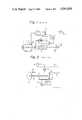
- FIG. 1is a block diagram of an automatic clutch control system in a conventional semiautomatic transmission
- FIG. 2is a partial schematic view of a clutch actuator shown in FIG. 1;
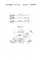
- FIG. 3(A)is a timing chart of drive current applied to solenoid values V 1 and V 2 ;
- FIG. 3(B)shows the quantity of oil flow through one solenoid valve V 1 ;
- FIG. 3(C)shows the quantity of oil flow through another solenoid valve V 2 ;
- FIG. 4is a block diagram of an automatic clutch control system according to the present invention.
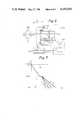
- FIG. 5is a block diagram of a hydraulic control circuit including the solenoid valves controlled by the controller shown in FIG. 4;
- FIG. 6is a block diagram for a portion of the automatic clutch control system shown in FIG. 4;
- FIGS. 7-9are graphs of relationships between clutch stroke and clutch moving time (FIG. 7) and between clutch stroke and clutch moving speed (FIG. 8 and FIG. 9);
- FIGS. 10(A)-(D)are timing charts for opening and closing of valves and the quantity of fluid flow therethrough;
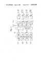
- FIG. 11is a basic block diagram of the controller 100 illustrated in FIG. 4.
- FIG. 12is a flow chart of a clutch control procedure performed in the controller 100 illustrated in FIG. 11.
- the rotation of an automobile engineis transmitted to the shaft of a transmission mechanism by a dry-type single-plate clutch.
- a hydraulic control actuatoris used to control the clutch engagement.
- the hydraulic control actuatorincludes a hydraulic cylinder used to engage and disengage the clutch and a plurality of solenoid valves used to control motion of the hydraulic cylinder. Control of the hydraulic actuator, i.e., control of the solenoid valves, is effected mechanically in manual transmissions and electronically in semiautomatic transmissions.
- reference numeral 1is an accelerator pedal, 1A an accelerator pedal sensor, 2 an engine, 2A an engine speed sensor, 3 a throttle actuator, 4 a clutch, 5 a transmission, 6 a clutch actuator, 6A a clutch stroke sensor, 7 a solenoid valve group, 8 an oil pump, 9 an oil tank, 10 a control unit, and 11 an automobile speed sensor.
- the control unit 10comprising a microcomputer, controls the throttle actuator 3 and the solenoid valve group 7 based on a signal transmitted from the accelerator pedal sensor 1A, a signal transmitted from the engine speed sensor 2A, a signal transmitted from the clutch stroke sensor 6A, and a signal transmitted from the automobile speed sensor 11.
- the control unit 10also feeds back the stroke signal transmitted from the clutch stroke sensor 6A to control the opening of the solenoid valve group 7 for engagement, slip, or disengagement of the clutch based on the clutch moving speed, as defined by clutch engagement, clutch slip, clutch disengagement, change in engine speed, automobile speed, and other driving conditions.
- the systemfeeds back a stroke signal transmitted from a clutch stroke sensor, engine speed sensor, and automobile speed sensor to control the duty ratio (ratio of opening and closing time of valve) of a solenoid valves by a control unit to obtain both a clutch moving speed and clutch moving time defined by engine speed, automobile speed, and other driving conditions.
- the hydraulic control actuatorcomprises a clutch actuator, i.e., an oil cylinder 6, and a plurality of solenoid valves (V 1 to V 3 ).
- a piston 6B equipped with a piston rod 6Cis provided in the oil cylinder 6.
- the solenoid valve V 1is provided for exhaust in a small diameter fluid passage
- the solenoid valve V 2is provided for exhaust in a large diameter fluid passage.
- the solenoid valve V 3is provided for controlling the supply of oil via a fluid passage having a diameter which may be different from that of the exhaust passages.
- FIGS. 3(A), 3(B), and 3(C)when a drive current having a pulse waveform as shown in FIG. 3(A) is applied to the solenoid valves V 1 and V 2 , the oil flow through the solenoid valve V 1 in the small diameter fluid passage is shown by FIG. 3(B), and the oil flow through the solenoid valve V 2 in the large diameter fluid passage is shown by FIG. 3(C).
- the oil flows through the solenoid valves V 1 and V 2are constant so long as the pulse waveform of the drive current is the same, i.e., has the same pulse width.
- the oil flowchanges when the pulse width becomes smaller or due to increasingly smaller diameters of fluid passages, used to achieve finer control. As a result the control of the hydraulic actuator becomes unstable. Accordingly, it is difficult to obtain precise control of the opening or closing of the solenoid valves to obtain the desired clutch moving speed and clutch moving time.
- the automatic clutch control system according to the present inventioncan be used with conventional dry-type single-plate clutches and sliding-mesh-type transmission.
- the change lever used in semiautomatic transmissionsis eliminated and a transmission changer (drive mechanism) is used instead.
- These clutch and drive mechanismsare controlled by a microcomputer controller.
- the clutch control system according to the present inventionis a fully automatic transmission using a conventional manual clutch and transmission.
- the automatic clutch control system depictedincludes many of the same components shown in FIG. 1, and includes a controller 100, a solenoid valve group 70, and a changer 12 as new components.
- the components which are the same in FIG. 1 and FIG. 4,are indicated by the same reference numerals.
- the clutch 4comprises a clutch pressure plate 4A, clutch disk 4B, diaphragm spring 4C, clutch release bearing 4D, clutch release lever 4E, clutch shaft 4F, and lever 4G.
- Reference numeral 2Bis an engine flywheel; 701, 701', 702, and 703 are solenoid valves in the solenoid group 70; B is a battery; SW a power switch associated with an ignition switch; and AC an accumulator.
- the clutch 4is controlled by controlling the opening or closing of the solenoid valves 701, 701', 702, and 703 using the controller 100.
- the controller 100comprises a microcomputer running a program which changes control with respect to driving conditions.
- solenoid valves 701 and 701'for example, are actuated by the controller 100, pressurized fluid is supplied to the oil cylinder 6 from the oil pump 8.
- the piston 6B of the oil cylinder 6is thus moved toward the right as indicated by the arrow line to disengage the clutch disk 4B.
- the solenoid valves 702 and 703are actuated by the controller 100, the pressurized fluid is exhausted from the oil cylinder 6.
- the piston 6Bthus moves in the reverse direction due to the action of a return spring (not shown) to re-engage the clutch disk 4B.
- the controller 100stores various parameters, for example, a to d shown in FIGS. 7 to 9, defining the relationship between the clutch stroke and clutch moving time or between the clutch stroke and clutch moving speed based on various driving conditions, such as upward or downward slopes, flat roads, and stopping.
- the controller 100uses these parameters a to d and the signal transmitted from the clutch stroke sensor 6A, for example, a potentiometer, to calculate desireable clutch moving speed and clutch moving time corresponding to the clutch stroke S and controls the solenoid valve group 70 based on the results of its calculations.
- the ordinateindicates the clutch stroke (S) and the abscissa indicates the clutch moving time (T).
- the lines I, II, and IIIindicate clutch engagement (clutch on), clutch slip (half clutch), and clutch disengagement (clutch off).
- the clutch moving timeis controlled by a predetermined gradually increasing value in the clutch operation from line III to line II and controlled by one of a set of predetermined gradually increasing values corresponding to a selected one of the driving condition parameters a to d in the clutch operation from line II to line I.
- the ordinatesindicate the clutch stroke (S) and the abscissas indicate the clutch moving speed (V).
- the clutch moving speedis controlled to maintain a constant value in the clutch operation from line III to line II.
- the clutch moving speedis controlled by one of a set of predetermined gradually decreasing values corresponding to a selected one of the driving condition parameters a to d in the clutch operation from line II to line I.
- the clutch moving speedis controlled by one of a set of predetermined constant values in the clutch operation from line II to near line I and by a predetermined constant value to line I.
- the open (“on") and closed (“off") timings of each solenoid valve 701, 701', 702, and 703are controlled by the controller 100.
- the "on” and “off” timingscan be independently selected by the controller 100.
- the quantity of oil flow through the valveschanges gradually at the leading edges and trailing edges of the waveforms shown in FIG. 10.
- the method for controlling the quantity of oil flow according to the present inventionis particularly advantageous when the solenoid valves 701, 701', 702, and 703 are controlled as shown in FIGS. 10(C) and 10(D).
- the solenoid valves 701 and 701'are provided in series in the supply side fluid passage, while the solenoid valves 702 and 703 are provided in parallel in the exhaust side fluid passage.
- the solenoid valvehas not been able to operate fast enough in accordance with a rapid succession of "on” and "off” instructions.
- the quantity of oil flow through the valves during "on" and "off” timinghas been unstable.
- valves 701, 701', 702, and 703can be independently performed by the controller 100. Consequently, it is possible to control the solenoid valves 701, 701', 702, and 703 to operate with exactly the right timings. A stable flow of oil is possible even with an extremely small overlap of time in the "on" position. Consequently, since the quantity of oil flow through each valve can be finely controlled by the microcomputer, the clutch moving speed and the clutch moving time can be controlled for various driving conditions.
- the controller 100mainly comprises analog-digital converters AD1 to AD4, an address modifier AM0, memories M1 to M4, a comparator and calculator CAL, counters CNT1 to CNT4, and flip-flop circuits FF1 to FF4.
- the address modifier AM0, comparator and calculator CAL, and counters CNTare incorporated in a central processing unit CPU.
- An analog output detected by, for example, the accelerator pedal sensor 1Ais applied to the analog-digital converter AD1.
- An analog output detected by, for example, the clutch stroke sensor 6Ais applied to the analog-digital converter AD2.
- the digital outputs from the analog-digital converters AD1 and AD2are applied to the memories M1 and M2, respectively, via the address modifier AM0.
- the digital outputsdesignate addresses in the memories (tables) M1 and M2.
- Data read from the tablesis supplied to the comparator and calculator CAL and appropriately processed.
- the resultant data and the pulse Gare applied to the counter CNT1 for presetting the counter CNT1 and for setting the flip-flop FF1.
- the transistor TR1turns on activating the solenoid valve 701.
- the counter CNT1sequentially counts down from the preset number based on a periodically input pulse T and resets the flip-flop circuit FF1 upon reaching zero.
- the output of the flip-flop circuit FF1is applied to the base of a transistor TR1.
- the solenoid valve 701is activated.
- the flip-flop FF1is reset upon the counter reaching zero, the transistor TR1 turns off and the solenoid valve 701 is deactivated. Accordingly, the larger the number preset in the counter CNT1, the longer the activated (on time) of the solenoid valve 701. The smaller the preset number, the longer the "on" time of the solenoid valve 701. If the gate value which controls output of the memory M1 is stored in another table, for example, memory M2, the clutch moving speed and clutch moving time can be controlled as shown in FIGS. 7 to 9.
- the signals from each sensori.e., the accelerator pedal sensor 1A, the engine speed sensor 2A, the clutch stroke sensor 6A, and the automobile speed sensor 11, are first applied to the analog-digital converters at step 1. These analog signals are converted to digital signals at step 2.
- the digital signals transmitted from the analog-digital convertersdesignate addresses in the tables at step 3.
- the stored datais read from the tables and applied to the comparator and calculator CAL at step 4.
- the comparator and calculator CALcompares the read data with pre-stored data of driving conditions a, b, c, and d and calculates differentials for obtaining clutch moving time and clutch moving speed based on commands transmitted from the central processing unit CPU at steps 5 and 6.
- the resultant datais applied to the counters, which sequentially count down from preset numbers based on the periodically input pulses at step 7.
- the flip-flop circuitsare reset by other periodically input pulses when the counts become zero at step 8.
- the outputs of the flip-flop circuitsare applied to the bases of the transistors and the transistors turn on.
- the solenoid valvesare activated by the current flowing through the transistors at step 9. Consequently, the cylinder stroke is controlled by the "on” or "off” timing of each valve at step 10. Therefore, the clutch stroke can be suitably controlled for all driving conditions.
Landscapes
- Engineering & Computer Science (AREA)
- Mechanical Engineering (AREA)
- Transportation (AREA)
- Physics & Mathematics (AREA)
- Fluid Mechanics (AREA)
- General Engineering & Computer Science (AREA)
- Chemical & Material Sciences (AREA)
- Combustion & Propulsion (AREA)
- Automation & Control Theory (AREA)
- Hydraulic Clutches, Magnetic Clutches, Fluid Clutches, And Fluid Joints (AREA)
Abstract
Description
1. Field of the Invention
The present invention relates to a clutch control system, more particularly to a method and apparatus for an automatic clutch control system using a microcomputer.
The present invention is advantageously used, for example, in automobiles having conventional dry-type single-plate clutches and sliding-mesh-type transmissions.
An automatic clutch control system according to the present invention can automatically control clutch moving time, clutch moving speed, and gear changes under a predetermined control program stored in a microcomputer, thus allowing easy driving under all driving conditions.
2. Description of the Prior Art
As is well known, three main types of transmissions are now in use for clutch control and gear change in automobiles: manual transmissions, using dry-type single-plate clutches and sliding-mesh-type transmissions, which are manually operated by a clutch pedal and a change lever; semiautomatic transmissions, also using dry-type single-plate clutches and sliding-mesh-type transmissions, which have a gear change mechanism manually operated by a change lever and a clutch automatically controlled by a computer; and automatic transmissions, for example, using torque converters and planetary-gear-type auxiliary transmissions, which are automatically controlled by a computer controller.
As is also well known, each of these types of transmissions have their own advantages and disadvantages. The main disadvantages of manual transmissions are troublesome operability, poor smoothness of change, and susceptibility of efficiency to driving characteristics of individual drivers. The main disadvantage of semiautomatic transmissions is poor smoothness of change. Finally, the main disadvantages of automatic transmissions are poor gas mileage, slow response time, and high cost.
Although technical improvements have been made alleviating the above disadvantages, these improvements are still not sufficient.
The primary object of the present invention is to provide an automatic clutch control system, for use in automobiles, using a microcomputer and eliminating the disadvantages in the prior art.
Another object of the present invention is to provide an automatic clutch control system enabling highly precise, automatic control of clutch moving time and clutch moving speed under various driving conditions.
Still another object of the present invention is to provide an automatic clutch control system enabling use of conventional dry-type single-plate clutches and sliding-mesh-type transmissions.
In accordance with the present invention, there is provided an apparatus for an automatic clutch control system, for use in automobiles, using a microcomputer, and comprising sensing means and control means. The sensing means include accelerator sensing means for sensing accelerator position; engine-speed sensing means for sensing engine speed; clutch stroke sensing means for sensing clutch stroke; and automobile speed sensing means for sensing automobile speed. Control is provided by the control means, preferably the microcomputer for controlling opening or closing of solenoid valves, gear change of a transmission, and opening or closing of a throttle actuator, based on predetermined stored data and based on signals transmitted from the accelerator, engine speed, clutch stroke and automobile speed sensing means. The control means provides automatic control of clutch moving time and clutch moving speed and easy driving under all driving conditions.
Moreover, there is provided a method for automatic clutch control, for automobiles, using a microcomputer, comprising the steps of detecting, comparing and controlling. The detecting includes detecting accelerator position by an accelerator pedal sensor, engine speed by an engine speed sensor, clutch stroke by a clutch stroke sensor, and automobile speed by an automobile speed sensor. The comparing includes comparing the sensor data with predetermined stored data and calculating clutch moving time and clutch moving speed based on predetermined data for various driving conditions. The controlling includes controlling opening or closing of solenoid valves based on signals generated from flip-flop circuits via counters activated by the calculations and controlling the clutch moving time and clutch moving speed using a clutch actuator controlled by the solenoid valves.
The present invention enables easy driving under all driving conditions and improved operability and gas mileage compared with conventional manual, semiautomatic, and fully automatic transmissions. Moreover, it can be used with dry-type single-plate clutches and sliding-mesh-type transmissions used in conventional manual and semiautomatic transmissions.
In the drawings,
FIG. 1 is a block diagram of an automatic clutch control system in a conventional semiautomatic transmission;
FIG. 2 is a partial schematic view of a clutch actuator shown in FIG. 1;
FIG. 3(A) is a timing chart of drive current applied to solenoid values V1 and V2 ;
FIG. 3(B) shows the quantity of oil flow through one solenoid valve V1 ;
FIG. 3(C) shows the quantity of oil flow through another solenoid valve V2 ;
FIG. 4 is a block diagram of an automatic clutch control system according to the present invention;
FIG. 5 is a block diagram of a hydraulic control circuit including the solenoid valves controlled by the controller shown in FIG. 4;
FIG. 6 is a block diagram for a portion of the automatic clutch control system shown in FIG. 4;
FIGS. 7-9 are graphs of relationships between clutch stroke and clutch moving time (FIG. 7) and between clutch stroke and clutch moving speed (FIG. 8 and FIG. 9);
FIGS. 10(A)-(D) are timing charts for opening and closing of valves and the quantity of fluid flow therethrough;
FIG. 11 is a basic block diagram of thecontroller 100 illustrated in FIG. 4; and
FIG. 12 is a flow chart of a clutch control procedure performed in thecontroller 100 illustrated in FIG. 11.
In general, the rotation of an automobile engine is transmitted to the shaft of a transmission mechanism by a dry-type single-plate clutch. To control the clutch engagement, a hydraulic control actuator is used. The hydraulic control actuator includes a hydraulic cylinder used to engage and disengage the clutch and a plurality of solenoid valves used to control motion of the hydraulic cylinder. Control of the hydraulic actuator, i.e., control of the solenoid valves, is effected mechanically in manual transmissions and electronically in semiautomatic transmissions.
Before describing the preferred embodiments of the present invention, an explanation will be given of a conventional clutch control system for a semiautomatic transmission using a dry-type single-plate clutch and a hydraulic control actuator.
Referring to FIG. 1,reference numeral 1 is an accelerator pedal, 1A an accelerator pedal sensor, 2 an engine, 2A an engine speed sensor, 3 a throttle actuator, 4 a clutch, 5 a transmission, 6 a clutch actuator, 6A a clutch stroke sensor, 7 a solenoid valve group, 8 an oil pump, 9 an oil tank, 10 a control unit, and 11 an automobile speed sensor.
Thecontrol unit 10, comprising a microcomputer, controls thethrottle actuator 3 and thesolenoid valve group 7 based on a signal transmitted from theaccelerator pedal sensor 1A, a signal transmitted from theengine speed sensor 2A, a signal transmitted from theclutch stroke sensor 6A, and a signal transmitted from theautomobile speed sensor 11. Thecontrol unit 10 also feeds back the stroke signal transmitted from theclutch stroke sensor 6A to control the opening of thesolenoid valve group 7 for engagement, slip, or disengagement of the clutch based on the clutch moving speed, as defined by clutch engagement, clutch slip, clutch disengagement, change in engine speed, automobile speed, and other driving conditions.
In other clutch control systems used in semiautomatic transmissions, the system feeds back a stroke signal transmitted from a clutch stroke sensor, engine speed sensor, and automobile speed sensor to control the duty ratio (ratio of opening and closing time of valve) of a solenoid valves by a control unit to obtain both a clutch moving speed and clutch moving time defined by engine speed, automobile speed, and other driving conditions.
However, it is difficult to obtain the desired clutch moving speed and clutch moving time by controlling the opening or closing of the solenoid valves because it is necessary to finely control the duty ratio of the opening or closing of the valves, which necessitates complex valve control.
The above problems will be explained in detail hereinafter with respect to FIG. 2 and FIGS. 3(A), 3(B) and 3(C). Referring to FIG. 2, as mentioned above, the hydraulic control actuator comprises a clutch actuator, i.e., anoil cylinder 6, and a plurality of solenoid valves (V1 to V3). Apiston 6B equipped with apiston rod 6C is provided in theoil cylinder 6. The solenoid valve V1 is provided for exhaust in a small diameter fluid passage, and the solenoid valve V2 is provided for exhaust in a large diameter fluid passage. The solenoid valve V3 is provided for controlling the supply of oil via a fluid passage having a diameter which may be different from that of the exhaust passages.
Although only two exhaust solenoid valves V1 and V2 are shown in the drawing, generally a plurality of fluid passages having the same diameters are provided in the actuator and each fluid passage is controlled by a solenoid valve. In the case shown in the drawing, the solenoid valve V2 is used for coarse control of the oil flow, and solenoid valve V1 for fine control of the oil flow.
Referring to FIGS. 3(A), 3(B), and 3(C) when a drive current having a pulse waveform as shown in FIG. 3(A) is applied to the solenoid valves V1 and V2, the oil flow through the solenoid valve V1 in the small diameter fluid passage is shown by FIG. 3(B), and the oil flow through the solenoid valve V2 in the large diameter fluid passage is shown by FIG. 3(C).
The oil flows through the solenoid valves V1 and V2 are constant so long as the pulse waveform of the drive current is the same, i.e., has the same pulse width. The oil flow, however, changes when the pulse width becomes smaller or due to increasingly smaller diameters of fluid passages, used to achieve finer control. As a result the control of the hydraulic actuator becomes unstable. Accordingly, it is difficult to obtain precise control of the opening or closing of the solenoid valves to obtain the desired clutch moving speed and clutch moving time.
An automatic clutch control system according to the present invention will now be explained in detail. As explained above, the automatic clutch control system according to the present invention can be used with conventional dry-type single-plate clutches and sliding-mesh-type transmission. In the present invention, the change lever used in semiautomatic transmissions is eliminated and a transmission changer (drive mechanism) is used instead. These clutch and drive mechanisms are controlled by a microcomputer controller. Accordingly, the clutch control system according to the present invention is a fully automatic transmission using a conventional manual clutch and transmission.
Referring to FIG. 4, the automatic clutch control system depicted includes many of the same components shown in FIG. 1, and includes acontroller 100, asolenoid valve group 70, and achanger 12 as new components. The components which are the same in FIG. 1 and FIG. 4, are indicated by the same reference numerals.
Referring to FIG. 5, theclutch 4 comprises aclutch pressure plate 4A, clutch disk 4B,diaphragm spring 4C, clutch release bearing 4D,clutch release lever 4E,clutch shaft 4F, andlever 4G.Reference numeral 2B is an engine flywheel; 701, 701', 702, and 703 are solenoid valves in thesolenoid group 70; B is a battery; SW a power switch associated with an ignition switch; and AC an accumulator.
Theclutch 4 is controlled by controlling the opening or closing of thesolenoid valves controller 100. Thecontroller 100 comprises a microcomputer running a program which changes control with respect to driving conditions. When solenoidvalves 701 and 701', for example, are actuated by thecontroller 100, pressurized fluid is supplied to theoil cylinder 6 from theoil pump 8. Thepiston 6B of theoil cylinder 6 is thus moved toward the right as indicated by the arrow line to disengage the clutch disk 4B. When thesolenoid valves controller 100, the pressurized fluid is exhausted from theoil cylinder 6. Thepiston 6B thus moves in the reverse direction due to the action of a return spring (not shown) to re-engage the clutch disk 4B.
This control of clutch engagement and disengagement will be explained in more detail hereinafter with respect to FIGS. 6, 7, 8, 9, and 10. Thecontroller 100 stores various parameters, for example, a to d shown in FIGS. 7 to 9, defining the relationship between the clutch stroke and clutch moving time or between the clutch stroke and clutch moving speed based on various driving conditions, such as upward or downward slopes, flat roads, and stopping. Thecontroller 100 uses these parameters a to d and the signal transmitted from theclutch stroke sensor 6A, for example, a potentiometer, to calculate desireable clutch moving speed and clutch moving time corresponding to the clutch stroke S and controls thesolenoid valve group 70 based on the results of its calculations.
The control modes will be explained in more detail with respect to FIGS. 7 to 9. Referring to FIG. 7, the ordinate indicates the clutch stroke (S) and the abscissa indicates the clutch moving time (T). The lines I, II, and III indicate clutch engagement (clutch on), clutch slip (half clutch), and clutch disengagement (clutch off). As is obvious from the graph, the clutch moving time is controlled by a predetermined gradually increasing value in the clutch operation from line III to line II and controlled by one of a set of predetermined gradually increasing values corresponding to a selected one of the driving condition parameters a to d in the clutch operation from line II to line I.
In FIGS. 8 and 9, the ordinates indicate the clutch stroke (S) and the abscissas indicate the clutch moving speed (V). In the control modes of both FIGS. 8 and 9, the clutch moving speed is controlled to maintain a constant value in the clutch operation from line III to line II. In FIG. 8, the clutch moving speed is controlled by one of a set of predetermined gradually decreasing values corresponding to a selected one of the driving condition parameters a to d in the clutch operation from line II to line I. In FIG. 9, the clutch moving speed is controlled by one of a set of predetermined constant values in the clutch operation from line II to near line I and by a predetermined constant value to line I.
Next, fine control of thesolenoid valves solenoid valve controller 100. The "on" and "off" timings can be independently selected by thecontroller 100. Generally, there is a time delay between the "on" and "off" timings in different valves. As a result, the quantity of oil flow through the valves changes gradually at the leading edges and trailing edges of the waveforms shown in FIG. 10.
In the case of two valves connected in series, such as 701 and 701', when both valves are turned on nearly simultaneously by drive currents i1 and i2 and are left on for a long time, the quantity of oil flow Q is indicated by the hatched area in FIG. 10(A). When the valves are both on for an overlapping short time, the quantity of oil flow Q is as shown in FIG. 10(B). When the upstream valve is changed from "on" to "off" and the downstream valve is simultaneously changed from "off" to "on," the quantity of oil flow is as shown in FIG. 10(C). As is obvious from the waveform shown in FIG. 10(D), the amount of overlapping of the "on" and "off" timing of the valves affects the quantity of oil flow.
The method for controlling the quantity of oil flow according to the present invention is particularly advantageous when thesolenoid valves solenoid valves 701 and 701' are provided in series in the supply side fluid passage, while thesolenoid valves
However, according to the present invention, "on" and "off" control of valves can be independently performed by thecontroller 100. Consequently, it is possible to control thesolenoid valves
Referring to FIG. 11, thecontroller 100 mainly comprises analog-digital converters AD1 to AD4, an address modifier AM0, memories M1 to M4, a comparator and calculator CAL, counters CNT1 to CNT4, and flip-flop circuits FF1 to FF4. The address modifier AM0, comparator and calculator CAL, and counters CNT are incorporated in a central processing unit CPU.
An analog output detected by, for example, theaccelerator pedal sensor 1A is applied to the analog-digital converter AD1. An analog output detected by, for example, theclutch stroke sensor 6A is applied to the analog-digital converter AD2. The digital outputs from the analog-digital converters AD1 and AD2 are applied to the memories M1 and M2, respectively, via the address modifier AM0. The digital outputs designate addresses in the memories (tables) M1 and M2.
Data read from the tables is supplied to the comparator and calculator CAL and appropriately processed. In the case of memory M1, the resultant data and the pulse G are applied to the counter CNT1 for presetting the counter CNT1 and for setting the flip-flop FF1. When the flip-flop FF1 is set, the transistor TR1 turns on activating thesolenoid valve 701. The counter CNT1 sequentially counts down from the preset number based on a periodically input pulse T and resets the flip-flop circuit FF1 upon reaching zero.
The output of the flip-flop circuit FF1 is applied to the base of a transistor TR1. When the transistor TR1 turns on as described above, thesolenoid valve 701 is activated. When the flip-flop FF1 is reset upon the counter reaching zero, the transistor TR1 turns off and thesolenoid valve 701 is deactivated. Accordingly, the larger the number preset in the counter CNT1, the longer the activated (on time) of thesolenoid valve 701. The smaller the preset number, the longer the "on" time of thesolenoid valve 701. If the gate value which controls output of the memory M1 is stored in another table, for example, memory M2, the clutch moving speed and clutch moving time can be controlled as shown in FIGS. 7 to 9.
Referring to FIG. 12, the signals from each sensor, i.e., theaccelerator pedal sensor 1A, theengine speed sensor 2A, theclutch stroke sensor 6A, and theautomobile speed sensor 11, are first applied to the analog-digital converters atstep 1. These analog signals are converted to digital signals atstep 2. The digital signals transmitted from the analog-digital converters designate addresses in the tables atstep 3. The stored data is read from the tables and applied to the comparator and calculator CAL atstep 4. The comparator and calculator CAL compares the read data with pre-stored data of driving conditions a, b, c, and d and calculates differentials for obtaining clutch moving time and clutch moving speed based on commands transmitted from the central processing unit CPU atsteps step 7. The flip-flop circuits are reset by other periodically input pulses when the counts become zero atstep 8. The outputs of the flip-flop circuits are applied to the bases of the transistors and the transistors turn on. The solenoid valves are activated by the current flowing through the transistors atstep 9. Consequently, the cylinder stroke is controlled by the "on" or "off" timing of each valve atstep 10. Therefore, the clutch stroke can be suitably controlled for all driving conditions.
Claims (13)
1. An automatic clutch control apparatus, for use in automobiles which have an accelerator pedal, a clutch actuated via solenoid valves, a throttle actuator on an engine and a transmission having changeable gears, comprising:
accelerator sensing means, coupled to the accelerator pedal, for sensing accelerator pedal position;
engine speed sensing means, coupled to the engine, for sensing engine speed;
clutch stroke sensing means, coupled to the clutch, for sensing clutch stroke;
automobile speed sensing means, coupled to the transmission, for sensing automobile speed; and
control means, operatively connected to said accelerator sensing means, said engine speed sensing means, said clutch stroke sensing means and said automobile speed sensing means, for controlling opening and closing of the solenoid valves, the gear change of the transmission and opening and closing of the throttle actuator, based on predetermined stored data and based on the position of the accelerator pedal, engine speed, clutch stroke and automobile speed, for automatic control of clutch moving time and clutch moving speed.
2. An apparatus as claimed in claim 1, wherein said clutch stroke sensing means comprises a potentiometer.
3. An apparatus as claimed in claim 1, wherein said control means comprises a microcomputer.
4. An automatic clutch control system for an automobile having an engine with a throttle, an accelerator pedal and a transmission with a clutch, said system comprising:
a throttle actuator, coupled to the throttle, for adjustment of the throttle;
a clutch actuator, coupled to the clutch, for controlling engagement and disengagement of the clutch;
solenoid valves, hydraulically connected to said clutch actuator, for controlling the movement of said clutch actuator;
clutch stroke sensing means, coupled to said clutch actuator, for sensing clutch stroke;
accelerator sensing means, coupled to the accelerator pedal, for sensing accelerator position;
engine speed sensing means, coupled to the engine, for sensing engine speed;
automobile speed sensing means, coupled to the transmission, for sensing automobile speed; and
control means, operatively connected to said clutch stroke sensing means, said accelerator sensing means, said engine speed sensing means and said automobile speed sensing means, for controlling opening and closing of the solenoid valves, gear change of the transmission and adjustments of the throttle actuator, in dependence upon the conditions sensed by said clutch stroke, accelerator, engine speed and automobile speed sensing means, to provide automatic control of clutch moving time and clutch moving speed.
5. An automatic clutch control system as claimed in claim 4, wherein said solenoid valves comprise a first group of at least two solenoid valves hydraulically connected to said clutch actuator in series and controlled by first overlapping timing signals from said control means.
6. An automatic clutch control system as claimed in claim 5,
further comprising supply and exhaust fluid passages hydraulically connecting said clutch actuator and said solenoid valves,
wherein said first group of at least two solenoid valves is connected to the supply fluid passage, and
wherein said solenoid valves further comprise a second group of at least two solenoid valves connected to the exhaust fluid passage in parallel and controlled by second overlapping timing signals from said control means.
7. An automatic clutch control system as claimed in claim 6, wherein said supply fluid passage has a first diameter and said exhaust fluid passage has a second diameter different than the first diameter.
8. A method of automatic clutch control for automobiles, using a microcomputer and comprising the steps of;
(a) detecting accelerator position by an accelerator pedal sensor, engine speed by an engine speed sensor, clutch stroke by a clutch stroke sensor, and automobile speed by an automobile speed sensor to generate sensor data;
(b) comparing the sensor data with predetermined stored data and calculating a clutch moving time and a clutch moving speed, based on the predetermined stored data, for various driving conditions;
(c) controlling at least one of opening and closing of solenoid valves based on signals generated from flip-flop circuits via counters activated by said calculating in step (b), two of the solenoid valves being series-connected solenoid valves and a quantity of fluid flow being controlled by overlapping timing of the least one of opening and closing of the series-connected solenoid valves using the microcomputer; and
(d) controlling the clutch moving time and clutch moving speed by means of a clutch actuator controlled by the solenoid valves.
9. A method of a automatic clutch control, for automobiles, using a microcomputer, comprising the steps of:
(a) detecting accelerator position by an accelerator pedal sensor, engine speed by an engine speed sensor, clutch stroke by a clutch stroke sensor, and automobile speed by an automobile speed sensor to generate sensor data;
(b) comparing the sensor data with predetermined stored data and calculating a clutch moving time and a clutch moving speed, based on the predetermined stored data, for various driving conditions;
(c) controlling at least one of opening and closing of solenoid valves based on signals generated from flip-flop circuits via counters activated by said calculating in step (b); and
(d) controlling the clutch moving time and speed by means of a clutch actuator controlled by the solenoid valves, using a predetermined value from clutch disengagement to clutch slip and using one of a set of predetermined values corresponding to a selected one of parameters of driving conditions from clutch slip to clutch engagement.
10. A method of automatic clutch control for automobiles, using a microcomputer and comprising the steps of:
(a) detecting accelerator position by an accelerator pedal sensor, engine speed by an engine speed sensor, clutch stroke by a clutch stroke sensor, and automobile speed by an automobile speed sensor to generate sensor data;
(b) comparing the sensor data with predetermined stored data and calculating a clutch moving time and a clutch moving speed, based on the predetermined stored data, for various driving conditions;
controlling at least one of opening and closing of solenoid valves based on signals generated from flip-flop circuits via counters activated by said calculating in step (b); and
(d) controlling the clutch moving speed and time by means of a clutch actuator controlled by the solenoid valves, using a constant value from clutch disengagement to clutch slip and using one of a set of predetermined values corresponding to a selected one of parameters of driving conditions from clutch slip to clutch engagement.
11. A method of automatic clutch control for automobiles, using a microcomputer and comprising the steps of:
(a) detecting accelerator position by an accelerator pedal sensor, engine speed by an engine speed sensor, clutch stroke by a clutch stroke sensor, and automobile speed by an automobile speed sensor to generate sensor data;
(b) comparing the sensor data with predetermined stored data and calculating a clutch moving time and a clutch moving speed, based on the predetermined stored data, for various driving conditions;
(c) controlling at least one of opening and closing of solenoid valves based on signals generated from flip-flop circuits via counters activated by said calculating in step (b); and
(d) controlling the clutch moving speed and time by means of a clutch actuator controlled by the solenoid valves, using one of a set of predetermined constant values corresponding to a selected one of parameters of driving conditions from clutch slip to near clutch engagement and then using a predetermined constant speed to clutch engagement.
12. A method of automatic clutch control for automobiles, using a microcomputer and comprising the steps of:
(a) detecting accelerator position by an accelerator pedal sensor, engine speed by an engine speed sensor, clutch stroke by a clutch stroke sensor, and automobile speed by an automobile speed sensor to generate sensor data;
(b) comparing the sensor data with predetermined stored data and calculating a clutch moving time and a clutch moving speed, based on the predetermined stored data, for various driving conditions;
(c) controlling at least one of opening and closing of solenoid valves based on signals generated from flip-flop circuits via counters activated by said calculating in step (b), two of the solenoid valves being provided in series in a supply side fluid passage and another two of the solenoid valves being provided in parallel in an exhaust side fluid passage, a quantity of fluid flow being controlled by overlapping timing of the at least one of opening and closing of the solenoid valves of both the supply and exhaust sides using the microcomputer; and
(d) controlling the clutch moving time and clutch moving speed by means of a clutch actuator controlled by the solenoid valves.
13. A method as claimed in claim 12, wherein step (c) comprises controlling the solenoid valves in the exhaust side fluid passage which has a first diameter and in the supply side fluid passage which has a second diameter different from the first diameter.
Applications Claiming Priority (4)
| Application Number | Priority Date | Filing Date | Title |
|---|---|---|---|
| JP58108248AJPS601448A (en) | 1983-06-16 | 1983-06-16 | clutch control device |
| JP58-108247 | 1983-06-16 | ||
| JP58108247AJPS601402A (en) | 1983-06-16 | 1983-06-16 | Actuator |
| JP58-108248 | 1983-06-16 |
Publications (1)
| Publication Number | Publication Date |
|---|---|
| US4591038Atrue US4591038A (en) | 1986-05-27 |
Family
ID=26448176
Family Applications (1)
| Application Number | Title | Priority Date | Filing Date |
|---|---|---|---|
| US06/620,090Expired - LifetimeUS4591038A (en) | 1983-06-16 | 1984-06-13 | Automatic clutch control system |
Country Status (1)
| Country | Link |
|---|---|
| US (1) | US4591038A (en) |
Cited By (30)
| Publication number | Priority date | Publication date | Assignee | Title |
|---|---|---|---|---|
| US4678069A (en)* | 1985-02-28 | 1987-07-07 | Isuzu Motors Limited | Clutch control system with variable clutch connection position |
| EP0244096A3 (en)* | 1986-04-18 | 1988-01-20 | Eaton Corporation | Method for controlling amt system including start from stop clutch & fuel control |
| US4799160A (en)* | 1984-11-07 | 1989-01-17 | Renault Agriculture | Clutch automation device |
| US4899857A (en)* | 1985-04-11 | 1990-02-13 | Mitsubishi Jidosha Kogyo Kabushiki Kaisha | Automatic transmission apparatus for vehicle |
| US4977992A (en)* | 1988-09-30 | 1990-12-18 | Diesel Kiki Co., Ltd. | Automatic transmission system for vehicles |
| US5002170A (en)* | 1987-10-07 | 1991-03-26 | Automotive Products Plc | Torque responsive clutch control |
| US5029678A (en)* | 1987-12-11 | 1991-07-09 | Isuzu Motors Limited | Automatic clutch control apparatus |
| US5060158A (en)* | 1988-09-27 | 1991-10-22 | Diesel Kiki Co., Ltd. | Apparatus for controlling clutches |
| US5065851A (en)* | 1989-07-24 | 1991-11-19 | Zexel Corporation | Clutch control unit |
| US5105922A (en)* | 1991-04-01 | 1992-04-21 | Dana Corporation | Hydraulic clutch and transmission actuating system |
| US5314050A (en)* | 1992-12-09 | 1994-05-24 | Eaton Corporation | Clutch mode control logic |
| US5325670A (en)* | 1989-02-10 | 1994-07-05 | Honda Giken Kogyo Kabushiki Kaisha | Clutch control device for transmission |
| US5360381A (en)* | 1989-11-10 | 1994-11-01 | Jason Swist | Automatic clutch control |
| US5439428A (en)* | 1994-02-22 | 1995-08-08 | Eaton Corporation | Method and apparatus for robust automatic clutch control with pid regulation |
| US5634867A (en)* | 1994-09-19 | 1997-06-03 | Eaton Corporation | Main clutch reengagement control for a double clutch downshift |
| US5769752A (en)* | 1995-12-19 | 1998-06-23 | Hyundai Motor Company | Control system for a vehicle transmission to prevent a stopped vehicle from rolling on a slope |
| FR2764249A1 (en)* | 1997-06-04 | 1998-12-11 | Luk Getriebe Systeme Gmbh | Control system for operation of motor vehicle clutch |
| US6145398A (en)* | 1998-02-20 | 2000-11-14 | New Venture Gear, Inc. | Electronically controlled shift system for a manual transmission |
| US6206803B1 (en) | 1997-04-16 | 2001-03-27 | Tranmissiones Tsp, S.A. De C.V. | Method and apparatus for operating a clutch in an automated mechanical transmission |
| US6223874B1 (en) | 1997-04-16 | 2001-05-01 | Transmissions Tsp, S.A. De C.V. | Apparatus for operating a clutch in an automated mechanical transmission |
| US6227999B1 (en) | 1997-07-09 | 2001-05-08 | Transmisiones Tsp, S.A. De C.V. | Method and apparatus for operating a clutch in an automated mechanical transmission |
| FR2803254A1 (en)* | 1999-12-30 | 2001-07-06 | Bosch Gmbh Robert | METHOD FOR THE COORDINATED CONTROL OF A VEHICLE ENGINE AND ITS AUTOMATIC CLUTCH DURING TORQUE REDUCTION DURING A CHANGE IN SPEED RATIO |
| US6309325B1 (en) | 1997-04-17 | 2001-10-30 | Transmission Tsp, S.A. De C.V. | Method and apparatus for operating a clutch in an automated mechanical transmission |
| US6319173B1 (en) | 1997-04-16 | 2001-11-20 | Transmisiones Tsp, S.A. De C.V. | Method and apparatus for operating a clutch in an automated mechanical transmission |
| US6364813B1 (en) | 1997-04-16 | 2002-04-02 | Transmisiones Tsp, S.A. De C.V. | Method and apparatus for operating a clutch in an automated mechanical transmission |
| US6397998B1 (en) | 1997-04-16 | 2002-06-04 | Transmisiones Tsp, S.A. De C.V. | Apparatus for operating a clutch in an automated mechanical transmission |
| WO2002061299A1 (en)* | 2001-01-30 | 2002-08-08 | Zf Sachs Ag | Hydraulically operated clutch system |
| US6540643B2 (en)* | 2000-06-12 | 2003-04-01 | Mitsubishi Kenki Kabushiki Kaisha | Control apparatus for synchromesh type automatic transmission |
| EP1818559A1 (en) | 2006-02-10 | 2007-08-15 | Toyota Jidosha Kabushiki Kaisha | Control device and control methods for automatic clutch |
| WO2014133893A1 (en)* | 2013-03-01 | 2014-09-04 | Wpt Power Corporation | Monotonic coupling assembly engagement |
Citations (3)
| Publication number | Priority date | Publication date | Assignee | Title |
|---|---|---|---|---|
| US4294341A (en)* | 1978-02-15 | 1981-10-13 | Swart Petrus H | Gear ratio selection apparatus |
| US4324322A (en)* | 1974-04-24 | 1982-04-13 | Sibeud Jean Paul | Method for the automatic control of a gearbox, in particular on a motor vehicle |
| US4497397A (en)* | 1981-02-24 | 1985-02-05 | Automotive Products Limited | Clutch control system |
- 1984
- 1984-06-13USUS06/620,090patent/US4591038A/ennot_activeExpired - Lifetime
Patent Citations (3)
| Publication number | Priority date | Publication date | Assignee | Title |
|---|---|---|---|---|
| US4324322A (en)* | 1974-04-24 | 1982-04-13 | Sibeud Jean Paul | Method for the automatic control of a gearbox, in particular on a motor vehicle |
| US4294341A (en)* | 1978-02-15 | 1981-10-13 | Swart Petrus H | Gear ratio selection apparatus |
| US4497397A (en)* | 1981-02-24 | 1985-02-05 | Automotive Products Limited | Clutch control system |
Cited By (35)
| Publication number | Priority date | Publication date | Assignee | Title |
|---|---|---|---|---|
| US4799160A (en)* | 1984-11-07 | 1989-01-17 | Renault Agriculture | Clutch automation device |
| US4678069A (en)* | 1985-02-28 | 1987-07-07 | Isuzu Motors Limited | Clutch control system with variable clutch connection position |
| US4899857A (en)* | 1985-04-11 | 1990-02-13 | Mitsubishi Jidosha Kogyo Kabushiki Kaisha | Automatic transmission apparatus for vehicle |
| EP0244096A3 (en)* | 1986-04-18 | 1988-01-20 | Eaton Corporation | Method for controlling amt system including start from stop clutch & fuel control |
| US5002170A (en)* | 1987-10-07 | 1991-03-26 | Automotive Products Plc | Torque responsive clutch control |
| US5029678A (en)* | 1987-12-11 | 1991-07-09 | Isuzu Motors Limited | Automatic clutch control apparatus |
| US5060158A (en)* | 1988-09-27 | 1991-10-22 | Diesel Kiki Co., Ltd. | Apparatus for controlling clutches |
| US4977992A (en)* | 1988-09-30 | 1990-12-18 | Diesel Kiki Co., Ltd. | Automatic transmission system for vehicles |
| US5325670A (en)* | 1989-02-10 | 1994-07-05 | Honda Giken Kogyo Kabushiki Kaisha | Clutch control device for transmission |
| US5065851A (en)* | 1989-07-24 | 1991-11-19 | Zexel Corporation | Clutch control unit |
| US5360381A (en)* | 1989-11-10 | 1994-11-01 | Jason Swist | Automatic clutch control |
| US5105922A (en)* | 1991-04-01 | 1992-04-21 | Dana Corporation | Hydraulic clutch and transmission actuating system |
| US5314050A (en)* | 1992-12-09 | 1994-05-24 | Eaton Corporation | Clutch mode control logic |
| US5378211A (en)* | 1992-12-09 | 1995-01-03 | Eaton Corporation | Clutch mode control logic |
| US5439428A (en)* | 1994-02-22 | 1995-08-08 | Eaton Corporation | Method and apparatus for robust automatic clutch control with pid regulation |
| US5634867A (en)* | 1994-09-19 | 1997-06-03 | Eaton Corporation | Main clutch reengagement control for a double clutch downshift |
| US5769752A (en)* | 1995-12-19 | 1998-06-23 | Hyundai Motor Company | Control system for a vehicle transmission to prevent a stopped vehicle from rolling on a slope |
| US6319173B1 (en) | 1997-04-16 | 2001-11-20 | Transmisiones Tsp, S.A. De C.V. | Method and apparatus for operating a clutch in an automated mechanical transmission |
| US6397998B1 (en) | 1997-04-16 | 2002-06-04 | Transmisiones Tsp, S.A. De C.V. | Apparatus for operating a clutch in an automated mechanical transmission |
| US6206803B1 (en) | 1997-04-16 | 2001-03-27 | Tranmissiones Tsp, S.A. De C.V. | Method and apparatus for operating a clutch in an automated mechanical transmission |
| US6223874B1 (en) | 1997-04-16 | 2001-05-01 | Transmissions Tsp, S.A. De C.V. | Apparatus for operating a clutch in an automated mechanical transmission |
| US6364813B1 (en) | 1997-04-16 | 2002-04-02 | Transmisiones Tsp, S.A. De C.V. | Method and apparatus for operating a clutch in an automated mechanical transmission |
| US6309325B1 (en) | 1997-04-17 | 2001-10-30 | Transmission Tsp, S.A. De C.V. | Method and apparatus for operating a clutch in an automated mechanical transmission |
| FR2764249A1 (en)* | 1997-06-04 | 1998-12-11 | Luk Getriebe Systeme Gmbh | Control system for operation of motor vehicle clutch |
| ES2155743A1 (en)* | 1997-06-04 | 2001-05-16 | Luk Getriebe Systeme Gbh | Timed controlled engaged state of an automatic clutch |
| US6227999B1 (en) | 1997-07-09 | 2001-05-08 | Transmisiones Tsp, S.A. De C.V. | Method and apparatus for operating a clutch in an automated mechanical transmission |
| US6145398A (en)* | 1998-02-20 | 2000-11-14 | New Venture Gear, Inc. | Electronically controlled shift system for a manual transmission |
| FR2803254A1 (en)* | 1999-12-30 | 2001-07-06 | Bosch Gmbh Robert | METHOD FOR THE COORDINATED CONTROL OF A VEHICLE ENGINE AND ITS AUTOMATIC CLUTCH DURING TORQUE REDUCTION DURING A CHANGE IN SPEED RATIO |
| US6540643B2 (en)* | 2000-06-12 | 2003-04-01 | Mitsubishi Kenki Kabushiki Kaisha | Control apparatus for synchromesh type automatic transmission |
| WO2002061299A1 (en)* | 2001-01-30 | 2002-08-08 | Zf Sachs Ag | Hydraulically operated clutch system |
| US20040045784A1 (en)* | 2001-01-30 | 2004-03-11 | Angelika Ebert | Hydraulically operated clutch system |
| US6889811B2 (en) | 2001-01-30 | 2005-05-10 | Zf Sachs Ag | Hydraulically operated clutch system |
| EP1818559A1 (en) | 2006-02-10 | 2007-08-15 | Toyota Jidosha Kabushiki Kaisha | Control device and control methods for automatic clutch |
| WO2014133893A1 (en)* | 2013-03-01 | 2014-09-04 | Wpt Power Corporation | Monotonic coupling assembly engagement |
| US9026331B2 (en) | 2013-03-01 | 2015-05-05 | Wpt Power Corporation | Monotonic coupling assembly engagement |
Similar Documents
| Publication | Publication Date | Title |
|---|---|---|
| US4591038A (en) | Automatic clutch control system | |
| EP0129417B1 (en) | Automatic clutch control system | |
| EP0661427B1 (en) | System for Selecting the Number of Cylinders to be operated in a multi Cylinder variable displacement Engine | |
| US4680988A (en) | Control for shock-free shift in an automatic transmission | |
| US4294341A (en) | Gear ratio selection apparatus | |
| US5431139A (en) | Air induction control system for variable displacement internal combustion engine | |
| US4510906A (en) | Accelerator pedal mechanism for optimizing fuel economy | |
| US4807497A (en) | System for integrally controlling automatic transmission and engine | |
| JPH0792141B2 (en) | Line pressure control device for automatic transmission | |
| JPH0781631B2 (en) | Line pressure control device for automatic transmission | |
| GB2048401A (en) | Line pressure control device of an automatic transmission | |
| DE2046381C3 (en) | Device for the automatic adjustment of the fuel supply to internal combustion engines with a downstream power shift transmission | |
| JPH0792140B2 (en) | Line pressure control device for automatic transmission | |
| SE462210B (en) | DEVICE FOR SETTING THE TORQUE OF A PRINCIPLE BURNING ENGINE, WHICH DRIVES A STEERING EXHAUST, IN DEPENDENT OF CHARACTERISTIC CURVES IN CONNECTIONS | |
| DE3243485A1 (en) | Automatic operating unit for a gearbox driven by means of an internal combustion engine | |
| JP3686094B2 (en) | Method and apparatus for adjusting spark ignition engine torque during gearshift operation | |
| US2713800A (en) | Device for controlling internal combustion engine drive | |
| CA1217070A (en) | Automatic clutch control system | |
| KR960005975B1 (en) | Engine and automatic transmission control | |
| US5035159A (en) | Shift control system for automatic transmission | |
| KR100491569B1 (en) | Controller for automatic transmission | |
| GB2522604A (en) | Managing Shift energy in a transmission of a vehicle | |
| JPS59194104A (en) | Fluid pressure actuator device | |
| JP3119013B2 (en) | Integrated control system for power train | |
| JPS639731A (en) | Clutch controlling device |
Legal Events
| Date | Code | Title | Description |
|---|---|---|---|
| AS | Assignment | Owner name:ISUZU MOTORS LIMITED 6-22-10, MINAMIOOI, SHINAGAWA Free format text:ASSIGNMENT OF ASSIGNORS INTEREST.;ASSIGNORS:ASAGI, YASUYOSHI;OGAWA, NORIAKI;KASAI, HITOSHI;AND OTHERS;REEL/FRAME:004273/0581 Effective date:19840601 | |
| STCF | Information on status: patent grant | Free format text:PATENTED CASE | |
| FEPP | Fee payment procedure | Free format text:PAYOR NUMBER ASSIGNED (ORIGINAL EVENT CODE: ASPN); ENTITY STATUS OF PATENT OWNER: LARGE ENTITY | |
| FPAY | Fee payment | Year of fee payment:4 | |
| FEPP | Fee payment procedure | Free format text:PAYOR NUMBER ASSIGNED (ORIGINAL EVENT CODE: ASPN); ENTITY STATUS OF PATENT OWNER: LARGE ENTITY Free format text:PAYER NUMBER DE-ASSIGNED (ORIGINAL EVENT CODE: RMPN); ENTITY STATUS OF PATENT OWNER: LARGE ENTITY | |
| FPAY | Fee payment | Year of fee payment:8 | |
| FPAY | Fee payment | Year of fee payment:12 |