US4590385A - Automatic starter - Google Patents
Automatic starterDownload PDFInfo
- Publication number
- US4590385A US4590385AUS06/552,194US55219483AUS4590385AUS 4590385 AUS4590385 AUS 4590385AUS 55219483 AUS55219483 AUS 55219483AUS 4590385 AUS4590385 AUS 4590385A
- Authority
- US
- United States
- Prior art keywords
- accelerator pedal
- pedal member
- starter
- attracting
- automatic
- Prior art date
- Legal status (The legal status is an assumption and is not a legal conclusion. Google has not performed a legal analysis and makes no representation as to the accuracy of the status listed.)
- Expired - Lifetime
Links
Images

Classifications
- F—MECHANICAL ENGINEERING; LIGHTING; HEATING; WEAPONS; BLASTING
- F02—COMBUSTION ENGINES; HOT-GAS OR COMBUSTION-PRODUCT ENGINE PLANTS
- F02N—STARTING OF COMBUSTION ENGINES; STARTING AIDS FOR SUCH ENGINES, NOT OTHERWISE PROVIDED FOR
- F02N11/00—Starting of engines by means of electric motors
- F02N11/08—Circuits specially adapted for starting of engines
- F02N11/0803—Circuits specially adapted for starting of engines characterised by means for initiating engine start or stop
- F—MECHANICAL ENGINEERING; LIGHTING; HEATING; WEAPONS; BLASTING
- F02—COMBUSTION ENGINES; HOT-GAS OR COMBUSTION-PRODUCT ENGINE PLANTS
- F02N—STARTING OF COMBUSTION ENGINES; STARTING AIDS FOR SUCH ENGINES, NOT OTHERWISE PROVIDED FOR
- F02N2200/00—Parameters used for control of starting apparatus
- F02N2200/10—Parameters used for control of starting apparatus said parameters being related to driver demands or status
- F02N2200/101—Accelerator pedal position
- Y—GENERAL TAGGING OF NEW TECHNOLOGICAL DEVELOPMENTS; GENERAL TAGGING OF CROSS-SECTIONAL TECHNOLOGIES SPANNING OVER SEVERAL SECTIONS OF THE IPC; TECHNICAL SUBJECTS COVERED BY FORMER USPC CROSS-REFERENCE ART COLLECTIONS [XRACs] AND DIGESTS
- Y10—TECHNICAL SUBJECTS COVERED BY FORMER USPC
- Y10T—TECHNICAL SUBJECTS COVERED BY FORMER US CLASSIFICATION
- Y10T74/00—Machine element or mechanism
- Y10T74/20—Control lever and linkage systems
- Y10T74/20528—Foot operated
- Y10T74/20534—Accelerator
Definitions
- the present inventionrelates to an improved automatic starter for use in a vehicle equipped with an automatic transmission.
- reference numeral 1indicates a battery mounted on a vehicle
- 2indicates a keyswitch having an ignition terminal IG connected to a later-described ignition circuit and a starter terminal ST connected to a starter circuit 3.
- Reference numeral 4indicates an ignition circuit which is connected to the ignition terminal IG.
- Reference numerals 5 and 6indicate a detecting unit and an accelerator pedal, respectively.
- Reference numeral 7indicates an acceleration detecting device which indicates a first acceleration switch 7a acting as a first acceleration detector and a second acceleration switch 7b acting as a second acceleration detector.
- Reference numerals 8, 9, 9a, 10 and 10aindicate a memory circuit, an ignition control circuit, an ignition relay, a starter control circuit and a starter relay, respectively.
- the keyswitch 2is closed at the ignition terminal IG.
- the memory circuit 8stores and sends out a signal which is generated by the detecting unit 5.
- the stored signalis applied to the ignition control circuit 9 and the starter control circuit 10 to effect an operational standby state in which the engine can be automatically started and stopped. If, in this state, the accelerator pedal 6 is depressed by a stroke deeper than a first set value and shallower than a second set value so as to effect the starting operation, the first acceleration switch 7a is closed to close the ignition relay 9a through the ignition control circuit 9 and the starter relay 10a through the starter control circuit 10. As a result, the ignition circuit 4 and the starter circuit 3 are energized to start the engine.
- the starter relay 10ais opened to block the supply of power to the starter circuit 3 so that the engine can be automatically started.
- the second acceleration switch 7bis employed together with the first acceleration switch 7a so as to detect the rate at which the accelerator pedal 6 is depressed and is used to prevent malfunctions.
- the automatic starter of the prior art thus far describedhas a defect in that the vehicle may be abruptly started if the accelerator pedal 6 is abruptly depressed.
- the present devicehas been conceived in view of the foregoing defect.
- the inventionprovides an automatic starter which prevents abrupt starting by a simple construction whereby the accelerator pedal is made extendible and contractible, by sliding movements, in two stages.
- the accelerator pedalis divided into two portions biased apart from one another by a spring.
- the second portionWhen the second portion is depressed toward the first portion, contacts are closed which energize the starter motor of the vehicle.
- a solenoidis energized which holds the two pedal portions together.
- FIG. 1is a schematic block diagram showing an automatic starter constructed according to the prior art
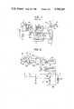
- FIG. 2is a diagram showing an automatic starter according to a preferred embodiment of the present device.
- FIG. 3is a sectional view showing a major portion of the accelerator pedal of FIG. 2.
- FIG. 2is a schematic circuit diagram showing an automatic starter according to one embodiment of the present device
- FIG. 3is a sectional view showing specific important portions of the accelerator pedal of FIG. 2.
- reference numeral 11indicates an accelerator pedal, the specific construction of which is shown by way of example in FIG. 3.
- Reference numeral 12indicates a first accelerator pedal member in which a rod 14 of a second accelerator pedal member 13 is slidably mounted at a central portion thereof.
- An electrically insulated depression plate 15forms a part of the second accelerator pedal member 13.
- a moving contact 16is embedded in the depression plate 15 and fixed integrally to the rod 14.
- a depression plate 17, which forms a part of the first accelerator pedal member 12,has inward protrusions 17a formed integrally therewith.
- Lead wires 20a and 20bare respectively connected to the lower ends of the respective responding contacts 18.
- a return coil spring 21is interposed under tension between a flange 14a formed at the central portion of the aforementioned rod 14 and the yoke 23 of a solenoid 22.
- An attracting and holding coil 24 wound on the yoke 23has terminals 24a and 24b leading to the outside of a case 25.
- the keyswitch 2is connected to one lead wire 20a of the accelerator pedal 11 while the contact of a relay 26a driven by the first control unit 26 is connected to the other lead wire 20b.
- That first control unit 26constitutes a logical sum switch in which a switch, made operative in response to ignition pulses which are transmitted from the ignition circuit 4 in a manner similar to the prior art automatic starter of FIG. 1, is connected in parallel with a switch made operative upon detection of the running operation of the vehicle by the action of a vehicular speed sensor.
- To the first control unit 26is connected the terminals 24a and 24b of the coil 24 which constitutes the solenoid 22 of the accelerator pedal 11 and which is made operative to simultaneously energize the aforementioned coil 24 and the coil of the relay 26a.
- Reference numeral 27indicates a second control unit which acts as an engine rotation detecting device which is composed of an alternator and a relay energized by the rotation of the engine.
- the terminal voltage of the alternatordrives the relay 27a, which is connected between the input terminals of the coils 28a and 28b constituting the electromagnetic switch 28 of the starter circuit 3 and the aforementioned relay 26a.
- normally closed contactsare used as the contacts of the aforementioned respective relays 26a and 27a.
- the first control unit 26may be a vehicular speed detecting switch.
- the remainder of the apparatusmay have a contruction similar to that shown in FIG. 1 and which is indicated with the same reference numerals.
- the first control unit 26drives the relay 26a to open its contact so that energization of the aforementioned electromagnetic switch 28 is released to automatically stop the starter 3a.
- the coil 24 of the accelerator pedal 11is energized by the aforementioned first control unit 26 so that the rod 14 of the second accelerator pedal member 13 is attracted and held by the solenoid 22 to operate integrally with the first accelerator pedal member 12.
- the accelerator pedalhas a construction whereby it is extendible and contractible in two stages, and the various control units are connected in series with the starter circuit.
- the starteris prevented from being engaged and energized during the normal opertion of the engine.
Landscapes
- Engineering & Computer Science (AREA)
- Chemical & Material Sciences (AREA)
- Combustion & Propulsion (AREA)
- Mechanical Engineering (AREA)
- General Engineering & Computer Science (AREA)
- Auxiliary Drives, Propulsion Controls, And Safety Devices (AREA)
- Control Of Vehicle Engines Or Engines For Specific Uses (AREA)
Abstract
Description
Claims (5)
Applications Claiming Priority (2)
| Application Number | Priority Date | Filing Date | Title |
|---|---|---|---|
| JP57-173657[U] | 1982-11-15 | ||
| JP1982173657UJPS5976424U (en) | 1982-11-15 | 1982-11-15 | automatic starting device |
Publications (1)
| Publication Number | Publication Date |
|---|---|
| US4590385Atrue US4590385A (en) | 1986-05-20 |
Family
ID=15964673
Family Applications (1)
| Application Number | Title | Priority Date | Filing Date |
|---|---|---|---|
| US06/552,194Expired - LifetimeUS4590385A (en) | 1982-11-15 | 1983-11-15 | Automatic starter |
Country Status (3)
| Country | Link |
|---|---|
| US (1) | US4590385A (en) |
| JP (1) | JPS5976424U (en) |
| DE (1) | DE3341354A1 (en) |
Cited By (7)
| Publication number | Priority date | Publication date | Assignee | Title |
|---|---|---|---|---|
| US4721872A (en)* | 1987-07-06 | 1988-01-26 | Simmons George W | Safety ground system |
| US4869220A (en)* | 1988-02-18 | 1989-09-26 | Siemens-Bendix Automotive Electronics L.P. | Accelerator control apparatus |
| USRE34302E (en)* | 1989-09-18 | 1993-07-06 | Siemens Automotive L.P. | Accelerating pedal for electronic throttle actuation system |
| US20020134606A1 (en)* | 2001-03-26 | 2002-09-26 | Kawasaki Jukogyo Kabushiki Kaisha | Starter device for a four wheeled all terrain vehicle and straddle-type four wheeled all terrain vehicle comprising the same |
| US6481404B1 (en)* | 2001-06-12 | 2002-11-19 | Ford Global Technologies, Inc. | Vehicle starting method and system |
| US6616573B2 (en) | 2001-09-21 | 2003-09-09 | Club Car, Inc. | Method and apparatus for eliminating power drainage in power sources used with starter-generators |
| WO2004068254A3 (en)* | 2003-01-24 | 2004-11-11 | Club Car Inc | Modular pedal assembly for vehicles |
Citations (6)
| Publication number | Priority date | Publication date | Assignee | Title |
|---|---|---|---|---|
| US1948198A (en)* | 1933-07-24 | 1934-02-20 | B D Emanuel | Automatic starter for internal combustion engines |
| US2399542A (en)* | 1930-12-08 | 1946-04-30 | Collins Douglas | Throttle and starter control mechanism |
| US2609514A (en)* | 1951-04-28 | 1952-09-02 | Gen Motors Corp | Engine starter control apparatus |
| US2799745A (en)* | 1954-08-23 | 1957-07-16 | Bendix Aviat Corp | Starting switch |
| US4179949A (en)* | 1978-06-28 | 1979-12-25 | Towmotor Corporation | Control pedal |
| US4237752A (en)* | 1978-10-06 | 1980-12-09 | Towmotor Corporation | Apparatus for controlling a plurality of mechanisms |
Family Cites Families (3)
| Publication number | Priority date | Publication date | Assignee | Title |
|---|---|---|---|---|
| CH190574A (en)* | 1935-08-23 | 1937-04-30 | Bosch Robert Ag | Device on motor vehicles with internal combustion engine for switching on the starter and for operating other organs of the vehicle. |
| DE1079891B (en)* | 1955-10-04 | 1960-04-14 | Zahnradfabrik Friedrichshafen | Device for stopping and starting internal combustion engines of motor vehicles with electrically switched gearboxes |
| DE2425204A1 (en)* | 1974-05-24 | 1975-12-11 | Kaltenbach & Voigt | Foot pedal control unit for dental equipment - has auxiliary on/off switch operable without interruption of main equipment |
- 1982
- 1982-11-15JPJP1982173657Upatent/JPS5976424U/enactiveGranted
- 1983
- 1983-11-15DEDE19833341354patent/DE3341354A1/enactiveGranted
- 1983-11-15USUS06/552,194patent/US4590385A/ennot_activeExpired - Lifetime
Patent Citations (6)
| Publication number | Priority date | Publication date | Assignee | Title |
|---|---|---|---|---|
| US2399542A (en)* | 1930-12-08 | 1946-04-30 | Collins Douglas | Throttle and starter control mechanism |
| US1948198A (en)* | 1933-07-24 | 1934-02-20 | B D Emanuel | Automatic starter for internal combustion engines |
| US2609514A (en)* | 1951-04-28 | 1952-09-02 | Gen Motors Corp | Engine starter control apparatus |
| US2799745A (en)* | 1954-08-23 | 1957-07-16 | Bendix Aviat Corp | Starting switch |
| US4179949A (en)* | 1978-06-28 | 1979-12-25 | Towmotor Corporation | Control pedal |
| US4237752A (en)* | 1978-10-06 | 1980-12-09 | Towmotor Corporation | Apparatus for controlling a plurality of mechanisms |
Cited By (15)
| Publication number | Priority date | Publication date | Assignee | Title |
|---|---|---|---|---|
| US4721872A (en)* | 1987-07-06 | 1988-01-26 | Simmons George W | Safety ground system |
| US4869220A (en)* | 1988-02-18 | 1989-09-26 | Siemens-Bendix Automotive Electronics L.P. | Accelerator control apparatus |
| USRE34574E (en)* | 1988-02-18 | 1994-04-05 | Siemens Automotive L.P. | Accelerator control apparatus |
| USRE34302E (en)* | 1989-09-18 | 1993-07-06 | Siemens Automotive L.P. | Accelerating pedal for electronic throttle actuation system |
| US6703717B2 (en)* | 2001-03-26 | 2004-03-09 | Kawasaki Jukogyo Kabushiki Kaisha | Starter device for a four wheeled all terrain vehicle and straddle-type four wheeled all terrain vehicle comprising the same |
| US20020134606A1 (en)* | 2001-03-26 | 2002-09-26 | Kawasaki Jukogyo Kabushiki Kaisha | Starter device for a four wheeled all terrain vehicle and straddle-type four wheeled all terrain vehicle comprising the same |
| US6481404B1 (en)* | 2001-06-12 | 2002-11-19 | Ford Global Technologies, Inc. | Vehicle starting method and system |
| US6616573B2 (en) | 2001-09-21 | 2003-09-09 | Club Car, Inc. | Method and apparatus for eliminating power drainage in power sources used with starter-generators |
| US20030232697A1 (en)* | 2001-09-21 | 2003-12-18 | Club Car, Inc. | Methods for eliminating power drainage in power sources used with starter-generators |
| WO2004068254A3 (en)* | 2003-01-24 | 2004-11-11 | Club Car Inc | Modular pedal assembly for vehicles |
| US20060230869A1 (en)* | 2003-01-24 | 2006-10-19 | Cosby Christopher D | Modular pedal assembly for vehicles |
| AU2004207396B2 (en)* | 2003-01-24 | 2009-06-11 | Club Car, Inc. | Modular pedal assembly for vehicles |
| US20110023652A1 (en)* | 2003-01-24 | 2011-02-03 | Cosby Christopher D | Modular pedal assembly for vehicles |
| KR101271301B1 (en)* | 2003-01-24 | 2013-06-04 | 클럽카 엘엘씨 | Modular pedal assembly for vehicles |
| US10296036B2 (en) | 2003-01-24 | 2019-05-21 | Club Car, Llc | Modular pedal assembly for vehicles |
Also Published As
| Publication number | Publication date |
|---|---|
| DE3341354A1 (en) | 1984-05-17 |
| JPS5976424U (en) | 1984-05-24 |
| JPS6210186Y2 (en) | 1987-03-10 |
Similar Documents
| Publication | Publication Date | Title |
|---|---|---|
| US4980526A (en) | Device and method for testing acceleration shock sensors | |
| US6653807B2 (en) | Starter control system for automotive vehicle | |
| GB1578406A (en) | Internal combustion engine starting circuit | |
| US4590385A (en) | Automatic starter | |
| US4769295A (en) | Battery and switch to be mounted on vehicles | |
| US7501790B2 (en) | Power supply system for a starter device with a reversible disconnection switch | |
| US5003190A (en) | Acceleration pickup, especially for release of occupant protecting devices in the event of accident | |
| US5217252A (en) | Actuator for use in emergency situation of vehicle | |
| US2759176A (en) | Battery current leak indicator | |
| US2663804A (en) | Autoamtic starter for internal-combustion engines | |
| US1936619A (en) | Engine starter controlling mechanism | |
| US1823950A (en) | Automatic automobile control | |
| US3944955A (en) | Solenoid switches | |
| US5210384A (en) | Acceleration sensor with magnetic biased mass and encapsulated contact terminals and resistor | |
| US3167659A (en) | Automatic starting control | |
| ES8308140A1 (en) | Electromagnetic switching device for a starting motor | |
| JP3919254B2 (en) | Solenoid for engine stop | |
| US1948198A (en) | Automatic starter for internal combustion engines | |
| US4394648A (en) | Brush wear detector system with latching relay | |
| JP2840968B2 (en) | Starting devices for acceleration switches and occupant protection devices | |
| US3452308A (en) | Magnetic switch | |
| US2307364A (en) | Electrical starting and generating system | |
| US5196660A (en) | Acceleration sensor | |
| US4893213A (en) | Multi-stage solenoid with time delayed actuation | |
| US2497462A (en) | Starter motor control system for internal-combustion engines |
Legal Events
| Date | Code | Title | Description |
|---|---|---|---|
| AS | Assignment | Owner name:MITSUBISHI DENKI KABUSHIKI KAISHA, NO. 2-3, MARUNO Free format text:ASSIGNMENT OF ASSIGNORS INTEREST.;ASSIGNORS:HAMANO, ISAO;MORISHITA, AKIRA;AKAE, YOSHIFUMI;AND OTHERS;REEL/FRAME:004520/0320 Effective date:19831028 Owner name:MITSUBISHI DENKI KABUSHIKI KAISHA,JAPAN Free format text:ASSIGNMENT OF ASSIGNORS INTEREST;ASSIGNORS:HAMANO, ISAO;MORISHITA, AKIRA;AKAE, YOSHIFUMI;AND OTHERS;REEL/FRAME:004520/0320 Effective date:19831028 | |
| STCF | Information on status: patent grant | Free format text:PATENTED CASE | |
| FEPP | Fee payment procedure | Free format text:PAYOR NUMBER ASSIGNED (ORIGINAL EVENT CODE: ASPN); ENTITY STATUS OF PATENT OWNER: LARGE ENTITY | |
| FPAY | Fee payment | Year of fee payment:4 | |
| FPAY | Fee payment | Year of fee payment:8 | |
| FEPP | Fee payment procedure | Free format text:PAYER NUMBER DE-ASSIGNED (ORIGINAL EVENT CODE: RMPN); ENTITY STATUS OF PATENT OWNER: LARGE ENTITY Free format text:PAYOR NUMBER ASSIGNED (ORIGINAL EVENT CODE: ASPN); ENTITY STATUS OF PATENT OWNER: LARGE ENTITY | |
| FPAY | Fee payment | Year of fee payment:12 |