US4589656A - Aerobic exercise device for increased user comfort - Google Patents
Aerobic exercise device for increased user comfortDownload PDFInfo
- Publication number
- US4589656A US4589656AUS06/668,984US66898484AUS4589656AUS 4589656 AUS4589656 AUS 4589656AUS 66898484 AUS66898484 AUS 66898484AUS 4589656 AUS4589656 AUS 4589656A
- Authority
- US
- United States
- Prior art keywords
- frame
- user
- shaft
- fan
- air
- Prior art date
- Legal status (The legal status is an assumption and is not a legal conclusion. Google has not performed a legal analysis and makes no representation as to the accuracy of the status listed.)
- Expired - Lifetime
Links
- 238000009423ventilationMethods0.000claimsabstractdescription21
- 230000001154acute effectEffects0.000claimsabstractdescription10
- 230000013011matingEffects0.000claimsdescription2
- 238000007599dischargingMethods0.000claims2
- 230000037361pathwayEffects0.000claims1
- 238000000034methodMethods0.000description6
- 230000008901benefitEffects0.000description5
- 210000000748cardiovascular systemAnatomy0.000description2
- 230000002526effect on cardiovascular systemEffects0.000description2
- 230000000694effectsEffects0.000description2
- 210000002414legAnatomy0.000description2
- 210000003205muscleAnatomy0.000description2
- 230000009182swimmingEffects0.000description2
- 230000009286beneficial effectEffects0.000description1
- 230000037396body weightEffects0.000description1
- 230000000747cardiac effectEffects0.000description1
- 230000010036cardiovascular benefitEffects0.000description1
- 210000003127kneeAnatomy0.000description1
- 238000012986modificationMethods0.000description1
- 230000004048modificationEffects0.000description1
- 230000003252repetitive effectEffects0.000description1
- 230000029058respiratory gaseous exchangeEffects0.000description1
- 230000036387respiratory rateEffects0.000description1
- 238000005728strengtheningMethods0.000description1
- 238000010998test methodMethods0.000description1
- 210000000689upper legAnatomy0.000description1
Images

Classifications
- A—HUMAN NECESSITIES
- A63—SPORTS; GAMES; AMUSEMENTS
- A63B—APPARATUS FOR PHYSICAL TRAINING, GYMNASTICS, SWIMMING, CLIMBING, OR FENCING; BALL GAMES; TRAINING EQUIPMENT
- A63B22/00—Exercising apparatus specially adapted for conditioning the cardio-vascular system, for training agility or co-ordination of movements
- A63B22/06—Exercising apparatus specially adapted for conditioning the cardio-vascular system, for training agility or co-ordination of movements with support elements performing a rotating cycling movement, i.e. a closed path movement
- A63B22/0605—Exercising apparatus specially adapted for conditioning the cardio-vascular system, for training agility or co-ordination of movements with support elements performing a rotating cycling movement, i.e. a closed path movement performing a circular movement, e.g. ergometers
- A63B2022/0635—Exercising apparatus specially adapted for conditioning the cardio-vascular system, for training agility or co-ordination of movements with support elements performing a rotating cycling movement, i.e. a closed path movement performing a circular movement, e.g. ergometers specially adapted for a particular use
- A63B2022/0652—Exercising apparatus specially adapted for conditioning the cardio-vascular system, for training agility or co-ordination of movements with support elements performing a rotating cycling movement, i.e. a closed path movement performing a circular movement, e.g. ergometers specially adapted for a particular use for cycling in a recumbent position
- A—HUMAN NECESSITIES
- A63—SPORTS; GAMES; AMUSEMENTS
- A63B—APPARATUS FOR PHYSICAL TRAINING, GYMNASTICS, SWIMMING, CLIMBING, OR FENCING; BALL GAMES; TRAINING EQUIPMENT
- A63B21/00—Exercising apparatus for developing or strengthening the muscles or joints of the body by working against a counterforce, with or without measuring devices
- A63B21/008—Exercising apparatus for developing or strengthening the muscles or joints of the body by working against a counterforce, with or without measuring devices using hydraulic or pneumatic force-resisters
- A63B21/0085—Exercising apparatus for developing or strengthening the muscles or joints of the body by working against a counterforce, with or without measuring devices using hydraulic or pneumatic force-resisters using pneumatic force-resisters
- A63B21/0088—Exercising apparatus for developing or strengthening the muscles or joints of the body by working against a counterforce, with or without measuring devices using hydraulic or pneumatic force-resisters using pneumatic force-resisters by moving the surrounding air
- A—HUMAN NECESSITIES
- A63—SPORTS; GAMES; AMUSEMENTS
- A63B—APPARATUS FOR PHYSICAL TRAINING, GYMNASTICS, SWIMMING, CLIMBING, OR FENCING; BALL GAMES; TRAINING EQUIPMENT
- A63B2220/00—Measuring of physical parameters relating to sporting activity
- A63B2220/70—Measuring or simulating ambient conditions, e.g. weather, terrain or surface conditions
- A63B2220/76—Wind conditions
Definitions
- the present inventionrelates to exercise devices, and in particular to devices for providing aerobic-type exercise wherein a user may remain stationary on said device while repeatedly moving particular portions of the body at relatively rapid rates for relatively long periods of time to thereby obtain benefits to the cardiovascular system.
- Aerobic exercisemay be defined as rapid repetitive movement of major body portions, particularly the arms and legs, so as to produce a rapid heartbeat and an increased rate of respiration.
- aerobic exercise beneficial to the cardiovascular systemrequires that the rapid heartbeat and increased respiratory rate be maintained for relatively extended periods of time, generally at least twenty minutes up to an hour or more.
- Exercise devicesattempting to provide appropriate solutions to the aforementioned problems have been proposed.
- the most common of these devicesare treadmills, "rowing" machines and stationary bicycle-like devices.
- Treadmillshave become a popular method of testing cardiac capabilities within a medical setting, but have not achieved great popularity as pure exercise devices, probably because the activity so resembles walking, jogging or running.
- Rowing machinesare somewhat more popular, but are primarily designed and used to provide anaerobic exercise such as development of leg and upper body muscles rather than more pure aerobic exercise in which the object is to raise the cardiovascular rate to a relatively high level for a relatively long period of time regardless of the strengthening obtained by various muscle groups.
- the stationary bicycle-like devicesusually comprise a traditional bicycle seat, bicycle handlebars, a bicycle frame and pedals located in the same relationship to the seat and the handlebars as pedals would be on an actual bicycle.
- Such bicycle-like devicesdo provide desirable aerobic exercise, but are not always suitable for the extended periods of exercise required to obtain the maximum benefits of aerobic exercise by most users. For example, some authorities recommend at least three periods of aerobic exercise per week, each extending for at least twenty minutes before cardiovascular improvement can be expected. Other authorities would consider such amounts relatively small and would recommend up to an hour a day for five or six days per week as a more desirable level of aerobic exercise.
- the narrow bicycle-type seat and the positioning of the handlebars, while necessary for the operation of an actual bicycle,are not particularly desirable for a device which is to remain stationary, and are unsuitable for extended periods of use.
- the object of the present inventionis accomplished by providing an aerobic exercise device, characterized by increased user comfort, especially during extended periods of use, which comprises an elongate frame, a housing enclosing the frame, stress imposing means carried by one end portion of the frame which includes pedal-driven fan means which imposes the stress on the user, and user supporting and positioning means carried by the other end portion of the frame opposite the stress imposing means and comprising a seat portion inclined from front to rear at a predetermined acute angle to the horizontal, and a backrest portion inclined at a predetermined acute angle to the vertical, with at least the backrest portion having ventilation openings therein which communicate with the front and rear surfaces of the backrest portion.
- air passage meanscommunicate with the discharge side of the fan means and also with the ventilation openings in the backrest portion and serve for directing air discharged by the fan means through the ventilation openings to the forward surface of said backrest portion and outwardly therefrom whereby the air cools the user and substantially increases the user's comfort, particularly during long periods of use.
- the stress imposing means and user supporting and positioning meansare disposed relative to each other so that the user's feet are at an elevation no lower than his or her hips and the user is semi-reclining in the supporting and positioning means for further increased comfort.
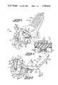
- FIG. 1is a perspective view of an exercise device incorporating the features of the present invention
- FIG. 2is a side elevational view of the exercise device shown in FIG. 1 with the housing removed;
- FIG. 3is a transverse sectional view taken substantially along line 3--3 in FIG. 2;
- FIG. 4is a perspective view of the exercise device shown in FIG. 1 looking upwardly into the housing;
- FIG. 5is a transverse sectional view taken substantially along line 5--5 in FIG. 2;
- FIG. 6is a sectional view taken substantially along line 6--6 in FIG. 2;
- FIG. 7is a sectional view taken substantially along line 7--7 in FIG. 6.
- Exercise device 10comprises an elongate frame 11 having a yoke-like forward end portion 11a and a rearward end portion 11b (FIG. 2)
- the frameis formed from a plurality of suitable structural members, such as metallic tubing having a square cross section (FIG. 3).
- the frame 11comprises a longitudinal pair of such structural members 11c, 11d extending from the forward end of the exercise device 10 to the rearward end, and forming an elongated, inverted U-shape.
- Frame 11further includes a pair of upright standards 11f, 11g connected to the forward ends of frame members 11c, 11d, respectively, (FIG. 4) and a brace member 11b connecting the upper ends of standards 11f, 11g to medial portions of frame members 11c, 11d (FIG. 2).
- a housing 12encloses the frame 11 and provides an overall aesthetic appearance to the exercise device 10. Housing 12 also isolates the moving parts of exercise device 10 from interference with the user or other animate or inanimate objects. It will be understood that housing 12 may be produced from several types of materials by known methods and that the particular nature of the material forming the housing does not constitute a part of the present invention. Similarly, while the shape of the housing 12 combines both aesthetic and functional qualities, it will be understood that the particular shape could be altered somewhat without departing from the spirit or scope of the present invention.
- exercise device 10includes stress imposing means carried by the forward end portion 11a of the frame 11.
- the stress imposing meanscomprises a shaft 13, (FIGS. 1 and 4) journaled for rotation on the upper ends of standards 11f, 11g and brace 11h of the frame 11, and having opposite ends thereof extending outwardly through opposite sides of the housing 12.
- Crank arms 14a and 14bare carried by or integral with opposite ends of the shaft 13 and pedals 15a and 15b are mounted on the outer ends of the crank arms 14a and 14b.
- the pedals 15a, 15binclude stirrups 16a, 16b which can be of assistance in positioning a user's feet on the pedals 15a and 15b.
- the stress imposing meansfurther includes fan means 17 positioned within housing 12 and which preferably comprises a pair of fans 18a, 18b (FIGS. 6 and 7).
- fans 18a, 18bare of the squirrel-cage type and each include a housing 19, 20 mounted on frame 11 and having input sides 19a, 20a and discharge sides 19b, 20b, respectively.
- the fans 18a, 18bfurther include rotors 21, 22 rotatably mounted within housings 19, 20 by a common shaft 23 extending therebetween.
- Fan means 17is driven by pedals 15a, 15b by means drivingly connecting the shaft 13 to the common shaft 23 such that fan means 17 applies a load on the shaft 13 and thereby on the pedals 15a, 15b.
- the means drivingly connecting shaft 13 to shaft 23comprises a second shaft 24, mounted on the standards 11f, 11g below and parallel to shaft 13 (FIGS. 2 and 4).
- a drive sprocket 25is mounted on the shaft 13 for rotation therewith and a driven sprocket 26 is similarly mounted on second shaft 24 in driving relation thereto.
- a chain 27is positioned about and drivingly connects drive sprocket 25 and driven sprocket 26.
- a drive pulley 31is mounted on the second shaft 24 for rotation therewith (FIG.
- a belt 33is positioned upon and drivingly connects the drive pulley 31 and the driven pulley 32 such that rotation of drive pulley 31 rotates driven pulley 32, common shaft 23 and fans 18a, 18b.
- the inverse mechanical advantageprovides an appropriately stressful load against which a user must exercise even though the load is applied by relatively small cylindrical fans moving correspondingly relatively small amounts of air.
- the present inventionthus provides a method of obtaining suitably stressful aerobic exercise using a minimum amount of load at the load source and an appropriate mechanical disadvantage.
- air inlet meansshown as the louvers 35 carried by the housing 12 (FIGS. 1 and 4).
- the louvers 35communicate with the input sides 19a and 20a of the fans 18a and 18b, respectively, and supply air thereto.
- air discharge meansshown in the form of shutters 36, are carried by the housing 12 and likewise communicate with the discharge sides 19b, 20b of the respective fans 18a and 18b and serve to discharge air from within the housing 12 to the exterior thereof.
- the louvers 35are positioned in sides of the housing 12 while the shutters 36 are positioned generally on upper middle portions of the housing 12. It will be understood, however, that the precise location of the air inlet means and the air discharge means may be varied without departing from the spirit and scope of the invention.
- the air discharge meansincludes means for varying the amount of air which may be discharged by the fan means 17 and thereby vary the load applied to the pedals 15a and 15b.
- this means for varying the loadcomprises butterfly valves 37a and 37b, respectively (FIGS. 2, 6 and 7).
- manually operable lever meansis connected to butterfly valves 37a, 37b and comprises a handle 52 pivotally connected to an arm 53 which in turn is connected to a bar 54 (FIG. 7), which operates links 55a and 55b.
- Links 55a, 55bare connected respectively to the butterfly valves 37a and 37b and when operated move the valves between open and closed positions.
- User supporting and positioning means 40is carried by the rear end portion 11b of frame 11, and comprises a seat portion 41 inclined from front to rear at a predetermined acute angle to the horizontal, and a backrest portion 42 which is inclined rearwardly from bottom to top at a predetermined angle to the vertical.
- Backrest portion 42has ventilation openings 43 therein which communicate with the front surface 44 and the rear surface 45 of the backrest portion 42.
- air passage meansis provided and preferably comprises a pair of ducts 46a and 46b which have the lower end portions thereof positioned under the seat portion 41 on opposite sides of the medial portion of frame 11. The remaining upper portions of ducts 46a, 46b are positioned along the rear surface of backrest portion 42 and communicate with the ventilation openings 43 in order to deliver air flow through the ventilation openings 43 to the front surface 44 of backrest portion 42.
- the ducts 46a, 46bcommunicate at their lower ends with the discharge means 36 of the fans 18a and 18b such that air discharged by the fans, enters the ducts 46a, 46b and is directed rearwardly beneath seat portion 41 and upwardly along the rear surface 45 of backrest portion 42.
- the airpasses through the ventilation openings 43 to the front surface 44 where it cools the user and substantially increases the user's comfort, particularly during long periods of use.
- the shutters 36are so positioned in the housing 12 that air discharged from the fans 18a and 18b is directed by the shutters 36 externally of and horizontally along the housing 12 into the ducts 46a and 46b. It will be understood that the present invention is not limited to the illustrated arrangement, but that other types of air passages could be used to communicate with the discharge sides of the fan means 17 in order to accomplish the same result without departing from the spirit or scope of the invention.
- the seat portion 41 of the user supporting and positioning means 40 and the shaft 13are positioned on the frame 11 with respect to one another such that the seat portion 41 is not higher than the shaft 13. In this manner a user's feet will be no lower than the user's hips, and in most cases will be higher.
- the particular relationship between the seat portion 41 and the shaft 13results in the user being in a semi-reclining position for even greater user comfort for several reasons.
- the seat portion 41provides broad support for a user's hips, as opposed to typical bicycle-type exercise devices in which a user's hips are not supported but which instead provide a narrow seat which forces the entirety of the user's weight to rest upon the lower portions of the user's spine and upon the user's crotch. This particular weight distribution can be very uncomfortable during extended periods of exercise.
- the exercise device 10preferably includes means for adjusting the position of the user supporting and positioning means 40 horizontally along the frame 11 which comprises a rack 56 (FIG. 2) extending longitudinally along and beneath the medial portion of the frame 11. Additionally, there is provided a pin 57 (FIG. 3) which is carried by a channel bracket 58 mounted on the bottom of seat portion 41 and is matingly receivable between the teeth of rack 56. Withdrawal of the pin from between the teeth of the rack 56 permits selective adjustment of the user supporting and positioning means 37 along the frame 11, while the mating reception of the pin 57 into the rack 56 causes the user supporting and positioning means 40 to remain at a selected predetermined location along the frame 11. In this manner, the user supporting and positioning means 40 can be quickly and easily moved forward or backward on the frame 11 to be adjusted to fit a variety of users and to maximize the comfort of individual users.
- a rack 56(FIG. 2) extending longitudinally along and beneath the medial portion of the frame 11.
- a pin 57(FIG. 3) which is carried
Landscapes
- Health & Medical Sciences (AREA)
- Cardiology (AREA)
- Vascular Medicine (AREA)
- General Health & Medical Sciences (AREA)
- Physical Education & Sports Medicine (AREA)
- Rehabilitation Tools (AREA)
- Aeration Devices For Treatment Of Activated Polluted Sludge (AREA)
- Chair Legs, Seat Parts, And Backrests (AREA)
Abstract
Description
Claims (12)
Priority Applications (5)
| Application Number | Priority Date | Filing Date | Title |
|---|---|---|---|
| US06/668,984US4589656A (en) | 1984-11-07 | 1984-11-07 | Aerobic exercise device for increased user comfort |
| CA000494842ACA1256139A (en) | 1984-11-07 | 1985-11-07 | Aerobic exercise device for increased user comfort |
| EP85308105AEP0181217B1 (en) | 1984-11-07 | 1985-11-07 | Aerobic exercise device for increased user comfort |
| JP60248136AJPS61179172A (en) | 1984-11-07 | 1985-11-07 | Aerobic gymnastics apparatus |
| DE8585308105TDE3578131D1 (en) | 1984-11-07 | 1985-11-07 | EXERCISE DEVICE WITH INCREASED WELL-BEING OF THE USER. |
Applications Claiming Priority (1)
| Application Number | Priority Date | Filing Date | Title |
|---|---|---|---|
| US06/668,984US4589656A (en) | 1984-11-07 | 1984-11-07 | Aerobic exercise device for increased user comfort |
Publications (1)
| Publication Number | Publication Date |
|---|---|
| US4589656Atrue US4589656A (en) | 1986-05-20 |
Family
ID=24684551
Family Applications (1)
| Application Number | Title | Priority Date | Filing Date |
|---|---|---|---|
| US06/668,984Expired - LifetimeUS4589656A (en) | 1984-11-07 | 1984-11-07 | Aerobic exercise device for increased user comfort |
Country Status (5)
| Country | Link |
|---|---|
| US (1) | US4589656A (en) |
| EP (1) | EP0181217B1 (en) |
| JP (1) | JPS61179172A (en) |
| CA (1) | CA1256139A (en) |
| DE (1) | DE3578131D1 (en) |
Cited By (104)
| Publication number | Priority date | Publication date | Assignee | Title |
|---|---|---|---|---|
| US4789153A (en)* | 1978-08-14 | 1988-12-06 | Brown Lawrence G | Exercise system |
| US4836536A (en)* | 1987-06-11 | 1989-06-06 | Arthur Jones | Apparatus for exercising muscles of the lower trunk of the human body |
| USD305348S (en) | 1988-07-06 | 1990-01-02 | Consumer Direct, Inc. | Pedal exerciser |
| USD306892S (en) | 1988-04-01 | 1990-03-27 | Bioform Engineering, Incorporated | Pedal and arm exercise machine |
| US4932650A (en)* | 1989-01-13 | 1990-06-12 | Proform Fitness Products, Inc. | Semi-recumbent exercise cycle |
| US4981324A (en)* | 1989-10-13 | 1991-01-01 | Law Ignace K | Ventilated back-seat support pad particularly for vehicles |
| US5000444A (en)* | 1988-06-02 | 1991-03-19 | Proform Fitness Products, Inc. | Dual action exercise cycle |
| US5048824A (en)* | 1990-07-11 | 1991-09-17 | Ya Te Industry Co., Ltd. | Air resistance excerciser with negative ion generator |
| US5051638A (en)* | 1989-12-19 | 1991-09-24 | Nathan Pyles | Magnetically variable air resistance wheel for exercise devices |
| US5178593A (en)* | 1991-07-05 | 1993-01-12 | Roberts Mark J | Combination stationary recumbent exercise apparatus and upper body exerciser |
| US5211613A (en)* | 1992-06-23 | 1993-05-18 | Schwinn Bicycle Company | Exercising machine with improved anti-drafting energy absorbing fanwheel |
| US5247853A (en)* | 1990-02-16 | 1993-09-28 | Proform Fitness Products, Inc. | Flywheel |
| USD340758S (en) | 1991-07-16 | 1993-10-26 | Cat Eye Co., Ltd. | Recumbent exercise bike |
| USD342299S (en) | 1991-07-12 | 1993-12-14 | Precor Incorporated | Recumbent exercise cycle |
| US5290212A (en)* | 1991-09-03 | 1994-03-01 | Roadmaster Corporation | Exercise cycle |
| USD347039S (en) | 1992-07-31 | 1994-05-17 | Precor Incorporated | Recumbent exercise cycle |
| US5443434A (en)* | 1993-06-17 | 1995-08-22 | Roadmaster Corporation | Exercise device |
| US5637057A (en)* | 1995-01-18 | 1997-06-10 | Collura; Frank | Tire trampoline apparatus |
| US5749807A (en)* | 1993-01-19 | 1998-05-12 | Nautilus Acquisition Corporation | Exercise apparatus and associated method including rheological fluid brake |
| US5992253A (en)* | 1997-04-08 | 1999-11-30 | Bioform Engineering, Inc. | Method and apparatus for converting reciprocating motion to single direction rotational motion |
| US6059701A (en)* | 1994-05-19 | 2000-05-09 | Cline Children Class Trust | Apparatus for exercising the lower back |
| US6106057A (en)* | 1999-09-22 | 2000-08-22 | Lee; Shih-Ping | Ventilation baby seat |
| US20010008861A1 (en)* | 1999-06-10 | 2001-07-19 | Concept Ii, Inc., Vermont Corporation | Machine-assisted exercising |
| US20020035017A1 (en)* | 2000-05-03 | 2002-03-21 | Victor Pertegaz-Esteban | Exercise equipment with multi-positioning handles |
| US20020137601A1 (en)* | 2001-03-23 | 2002-09-26 | Tobias Andrew J. | Exercise device |
| US6629724B2 (en) | 2001-01-05 | 2003-10-07 | Johnson Controls Technology Company | Ventilated seat |
| US20030216227A1 (en)* | 2002-05-16 | 2003-11-20 | Smith Paul Vaughn | Device for directing air flow at users of air resisted exercise machines |
| US20040036326A1 (en)* | 2002-07-03 | 2004-02-26 | Goran Bajic | Automotive vehicle seat insert |
| US20040164594A1 (en)* | 2002-12-18 | 2004-08-26 | Stefan Stoewe | Air conditioned seat and air conditioning apparatus for a ventilated seat |
| US6786541B2 (en) | 2001-01-05 | 2004-09-07 | Johnson Controls Technology Company | Air distribution system for ventilated seat |
| US20040189061A1 (en)* | 2001-07-28 | 2004-09-30 | Dirk Hartwich | Air-conditioned upholstered element for the seat of a motor vehicle |
| US6857697B2 (en) | 2002-08-29 | 2005-02-22 | W.E.T. Automotive Systems Ag | Automotive vehicle seating comfort system |
| US20050066505A1 (en)* | 2003-09-25 | 2005-03-31 | W.E.T. Automotive Systems Ag | Method for ventilating a seat |
| US20050067401A1 (en)* | 2003-09-25 | 2005-03-31 | W.E.T. Automotive Systems Ag | Control system for operating automotive vehicle components |
| US20050093347A1 (en)* | 2003-10-17 | 2005-05-05 | W.E.T. Automotive Systems Ag | Automotive vehicle seat having a comfort system |
| US20050140189A1 (en)* | 2003-10-17 | 2005-06-30 | W.E.T. Automotive Systems Ag | Automotive vehicle seat insert |
| GB2409651A (en)* | 2004-01-02 | 2005-07-06 | Jiann-Bang Liou | Exercise device with cooling fan |
| US20050173950A1 (en)* | 2003-12-01 | 2005-08-11 | W.E.T. Automotive System Ag | Valve layer for a seat |
| EP1652556A1 (en)* | 2004-10-28 | 2006-05-03 | Hai-Pin Kuo | Exerciser having adjustable seat |
| US7040710B2 (en) | 2001-01-05 | 2006-05-09 | Johnson Controls Technology Company | Ventilated seat |
| US7070545B2 (en) | 2002-07-01 | 2006-07-04 | Nautilus, Inc. | Leg press and abdominal crunch exercise machine |
| US20060158011A1 (en)* | 2004-11-02 | 2006-07-20 | W.E.T. Automotive Systems Ag | Molded layer for a seat insert |
| US7083554B1 (en) | 1997-02-27 | 2006-08-01 | Nautilus, Inc. | Exercise machine with infinite position range limiter and automatic belt tensioning system |
| US7115080B2 (en) | 2002-08-01 | 2006-10-03 | Nautilus, Inc. | Collapsible seat for combination hack squat and leg press machine |
| US20060249995A1 (en)* | 2005-04-20 | 2006-11-09 | Stefan Stoewe | Air conditioning system for a seat |
| US20060290175A1 (en)* | 2003-04-08 | 2006-12-28 | Johnson Controls Gmbh | Vehicle seat |
| US7172532B2 (en) | 2001-01-19 | 2007-02-06 | Nautilus, Inc. | Exercise device tubing |
| US7175570B2 (en) | 1997-02-18 | 2007-02-13 | Nautilus, Inc. | Exercise bicycle frame |
| US7213876B2 (en) | 2002-12-18 | 2007-05-08 | W.E.T. Automotive System Ag | Vehicle seat and associated air conditioning apparatus |
| US20070188007A1 (en)* | 2005-08-19 | 2007-08-16 | W.E.T. Automotive Systems Ag | Automotive vehicle seat insert |
| US7261371B2 (en) | 2001-12-19 | 2007-08-28 | Johnson Controls Gmbh | Ventilation system for an upholstery part |
| US20070215781A1 (en)* | 2006-03-17 | 2007-09-20 | Nautilus, Inc. | Mechanism and method for adjusting seat height for exercise equipment |
| US20080111403A1 (en)* | 2006-11-14 | 2008-05-15 | W.E.T. Automotive Systems Ag & Odelzhausen And Proseat Gmbh & Co. Kg | Module for a cushion |
| US20080257666A1 (en)* | 2007-04-17 | 2008-10-23 | Joseph Gelb | System for Cooling a Disc Brake Rotor and Collecting Brake Pad Waste |
| US20090253362A1 (en)* | 2008-04-08 | 2009-10-08 | W.E.T Automotive Systems Ag | Ventilation means |
| US20100227542A1 (en)* | 2009-03-09 | 2010-09-09 | Richard Goldmann | Apparatus for cooling an exerciser for use with an exercise machine |
| US20100273617A1 (en)* | 2009-04-22 | 2010-10-28 | Mills Alden M | Exercise device |
| US20110082015A1 (en)* | 2009-10-02 | 2011-04-07 | Concept Ii, Inc. | Exercising |
| US7922635B2 (en) | 2000-03-10 | 2011-04-12 | Nautilus, Inc. | Adjustable-load unitary multi-position bench exercise unit |
| US20110111923A1 (en)* | 2007-08-30 | 2011-05-12 | Milan Bacanovic | Ergometric training device |
| USD643483S1 (en)* | 2010-07-01 | 2011-08-16 | Precor Incorporated | Seat back for an exercise device |
| USD650870S1 (en)* | 2010-10-25 | 2011-12-20 | Technogym S.P.A. | Exercise device |
| USD650871S1 (en)* | 2011-04-26 | 2011-12-20 | Nustep, Inc. | Recumbent stepper |
| EP2468569A1 (en)* | 2010-12-23 | 2012-06-27 | Chen-Chang Lin | Ventilative car seat back |
| US8777320B2 (en) | 2008-12-21 | 2014-07-15 | W.E.T. Automotive Systems Ag | Ventilation system |
| US9162769B2 (en) | 2010-04-06 | 2015-10-20 | Gentherm Gmbh | Occupancy sensor that measures electric current through a heating element |
| US9283879B2 (en) | 2011-12-26 | 2016-03-15 | Gentherm Gmbh | Air conveyor |
| US9434284B2 (en) | 2011-11-17 | 2016-09-06 | Gentherm Gmbh | Thermostat device |
| US9448017B2 (en) | 2011-12-09 | 2016-09-20 | Gentherm Gmbh | Temperature control system for an electrochemical voltage source |
| US9468045B2 (en) | 2011-04-06 | 2016-10-11 | Gentherm Gmbh | Heating device for complexly formed surfaces |
| US9676308B2 (en) | 2011-08-19 | 2017-06-13 | Gentherm Gmbh | Heating device |
| US9695828B2 (en) | 2012-07-25 | 2017-07-04 | Gentherm Gmbh | Air delivery device |
| US20180290015A1 (en)* | 2017-04-10 | 2018-10-11 | Oma Metal Industrial Co., Ltd. | Elliptical trainer |
| US10188890B2 (en) | 2013-12-26 | 2019-01-29 | Icon Health & Fitness, Inc. | Magnetic resistance mechanism in a cable machine |
| US10252109B2 (en) | 2016-05-13 | 2019-04-09 | Icon Health & Fitness, Inc. | Weight platform treadmill |
| US10258828B2 (en) | 2015-01-16 | 2019-04-16 | Icon Health & Fitness, Inc. | Controls for an exercise device |
| US10272317B2 (en) | 2016-03-18 | 2019-04-30 | Icon Health & Fitness, Inc. | Lighted pace feature in a treadmill |
| US10279212B2 (en) | 2013-03-14 | 2019-05-07 | Icon Health & Fitness, Inc. | Strength training apparatus with flywheel and related methods |
| US10293211B2 (en) | 2016-03-18 | 2019-05-21 | Icon Health & Fitness, Inc. | Coordinated weight selection |
| US10343017B2 (en) | 2016-11-01 | 2019-07-09 | Icon Health & Fitness, Inc. | Distance sensor for console positioning |
| US10376736B2 (en) | 2016-10-12 | 2019-08-13 | Icon Health & Fitness, Inc. | Cooling an exercise device during a dive motor runway condition |
| US10426989B2 (en) | 2014-06-09 | 2019-10-01 | Icon Health & Fitness, Inc. | Cable system incorporated into a treadmill |
| US10433612B2 (en) | 2014-03-10 | 2019-10-08 | Icon Health & Fitness, Inc. | Pressure sensor to quantify work |
| US10441844B2 (en) | 2016-07-01 | 2019-10-15 | Icon Health & Fitness, Inc. | Cooling systems and methods for exercise equipment |
| US10471299B2 (en) | 2016-07-01 | 2019-11-12 | Icon Health & Fitness, Inc. | Systems and methods for cooling internal exercise equipment components |
| US10478660B2 (en) | 2015-05-27 | 2019-11-19 | Woodway Usa, Inc. | Recumbent therapeutic and exercise device |
| US10493349B2 (en) | 2016-03-18 | 2019-12-03 | Icon Health & Fitness, Inc. | Display on exercise device |
| US10500473B2 (en) | 2016-10-10 | 2019-12-10 | Icon Health & Fitness, Inc. | Console positioning |
| US10537764B2 (en) | 2015-08-07 | 2020-01-21 | Icon Health & Fitness, Inc. | Emergency stop with magnetic brake for an exercise device |
| US10543395B2 (en) | 2016-12-05 | 2020-01-28 | Icon Health & Fitness, Inc. | Offsetting treadmill deck weight during operation |
| US10561894B2 (en) | 2016-03-18 | 2020-02-18 | Icon Health & Fitness, Inc. | Treadmill with removable supports |
| US10561877B2 (en) | 2016-11-01 | 2020-02-18 | Icon Health & Fitness, Inc. | Drop-in pivot configuration for stationary bike |
| US10625114B2 (en) | 2016-11-01 | 2020-04-21 | Icon Health & Fitness, Inc. | Elliptical and stationary bicycle apparatus including row functionality |
| US10625137B2 (en) | 2016-03-18 | 2020-04-21 | Icon Health & Fitness, Inc. | Coordinated displays in an exercise device |
| US10661114B2 (en) | 2016-11-01 | 2020-05-26 | Icon Health & Fitness, Inc. | Body weight lift mechanism on treadmill |
| US10702736B2 (en) | 2017-01-14 | 2020-07-07 | Icon Health & Fitness, Inc. | Exercise cycle |
| US10729965B2 (en) | 2017-12-22 | 2020-08-04 | Icon Health & Fitness, Inc. | Audible belt guide in a treadmill |
| US10953305B2 (en) | 2015-08-26 | 2021-03-23 | Icon Health & Fitness, Inc. | Strength exercise mechanisms |
| EP3804820A1 (en) | 2019-10-08 | 2021-04-14 | Life Fitness, LLC | Exercise machines having a resistance fan that directs air for cooling a user |
| US11173816B2 (en) | 2015-07-31 | 2021-11-16 | Gentherm Gmbh | Air conditioner device for a seat |
| US11298284B2 (en) | 2017-02-10 | 2022-04-12 | Woodway Usa, Inc. | Motorized recumbent therapeutic and exercise device |
| US11451108B2 (en) | 2017-08-16 | 2022-09-20 | Ifit Inc. | Systems and methods for axial impact resistance in electric motors |
| US11919428B2 (en) | 2016-04-28 | 2024-03-05 | Gentherm Automotive Systems (China) Ltd. | Occupant supporting device and its temperature management system |
| US12343589B1 (en) | 2023-02-17 | 2025-07-01 | Daniel Bishop | Treadmill with calibrated airflow |
Families Citing this family (4)
| Publication number | Priority date | Publication date | Assignee | Title |
|---|---|---|---|---|
| JPS63125269A (en)* | 1986-11-15 | 1988-05-28 | 松下電工株式会社 | Bicycle training machine |
| AU5095693A (en)* | 1992-08-26 | 1994-03-15 | Nordictrack, Inc. | Multi-purpose exercise chair |
| CN106075922A (en)* | 2016-08-15 | 2016-11-09 | 福州品行科技发展有限公司 | There is the Hobbyhorse of air-cleaning function |
| CN111672061A (en)* | 2020-05-12 | 2020-09-18 | 武汉地衣科技有限公司 | Intelligent spinning seat with ventilation function |
Citations (18)
| Publication number | Priority date | Publication date | Assignee | Title |
|---|---|---|---|---|
| GB189406738A (en)* | 1894-04-04 | 1895-02-02 | John Long | An Improved Draught-creating Device for Use in Kindling Fires. |
| US681565A (en)* | 1901-02-15 | 1901-08-27 | Orlando B Mccune | Bicycle-fan. |
| FR800679A (en)* | 1935-04-16 | 1936-07-16 | Nessi Freres & Cie | Ventilation improvements |
| US2255864A (en)* | 1940-07-05 | 1941-09-16 | Goebel M Stephens | Exercise and massage machine |
| US2758532A (en)* | 1952-08-21 | 1956-08-14 | Raymond H Awe | Ventilated back rest for a vehicle seat |
| US2788211A (en)* | 1952-04-09 | 1957-04-09 | Ivanoff Peter Dimitry | Amusement and therapeutic device |
| US2826135A (en)* | 1954-04-21 | 1958-03-11 | American Motors Corp | Seat construction |
| US3283997A (en)* | 1965-05-14 | 1966-11-08 | Gen Am Transport | Portable ventilators |
| US3550523A (en)* | 1969-05-12 | 1970-12-29 | Irving Segal | Seat construction for automotive air conditioning |
| US3712613A (en)* | 1971-05-05 | 1973-01-23 | J Feather | Exercising machine |
| US3751033A (en)* | 1971-12-15 | 1973-08-07 | W Rosenthal | Combination of a chair and pedaling device |
| US4082264A (en)* | 1976-12-07 | 1978-04-04 | Santos James P | Stationary exercise bicycle |
| US4140312A (en)* | 1975-11-21 | 1979-02-20 | Buchmann Rudolf Ch | Stationary exercise bicycle |
| US4285515A (en)* | 1979-10-03 | 1981-08-25 | Gezari Daniel Y | Surgical ergometer table |
| US4358105A (en)* | 1980-08-21 | 1982-11-09 | Lifecycle, Inc. | Programmed exerciser apparatus and method |
| US4372551A (en)* | 1980-11-28 | 1983-02-08 | Victoreen, Inc. | Cardiac stress table |
| EP0121186A1 (en)* | 1983-03-30 | 1984-10-10 | C.I.M. Costruzioni Industriali Metalliche S.n.c. di Germano CASSINI & C. | Stand device for holding a bicycle stationary while simulating road running conditions |
| US4537396A (en)* | 1982-06-24 | 1985-08-27 | Repco Ltd. | Energy absorber for exercising machines |
Family Cites Families (3)
| Publication number | Priority date | Publication date | Assignee | Title |
|---|---|---|---|---|
| FR1335110A (en)* | 1962-07-05 | 1963-08-16 | Braking device, in particular for mechanotherapy apparatus | |
| CH457230A (en)* | 1966-04-14 | 1968-05-31 | Frederic Moreillon Raymond | Device for gymnastic exercises and rowing training in the home |
| JPS5154856A (en)* | 1974-11-08 | 1976-05-14 | Nippon Kokuen Kogyo Kk | Atsuenrooruyo kokuenkeikokeijunkatsuzai |
- 1984
- 1984-11-07USUS06/668,984patent/US4589656A/ennot_activeExpired - Lifetime
- 1985
- 1985-11-07JPJP60248136Apatent/JPS61179172A/enactivePending
- 1985-11-07DEDE8585308105Tpatent/DE3578131D1/ennot_activeExpired - Fee Related
- 1985-11-07CACA000494842Apatent/CA1256139A/ennot_activeExpired
- 1985-11-07EPEP85308105Apatent/EP0181217B1/ennot_activeExpired
Patent Citations (18)
| Publication number | Priority date | Publication date | Assignee | Title |
|---|---|---|---|---|
| GB189406738A (en)* | 1894-04-04 | 1895-02-02 | John Long | An Improved Draught-creating Device for Use in Kindling Fires. |
| US681565A (en)* | 1901-02-15 | 1901-08-27 | Orlando B Mccune | Bicycle-fan. |
| FR800679A (en)* | 1935-04-16 | 1936-07-16 | Nessi Freres & Cie | Ventilation improvements |
| US2255864A (en)* | 1940-07-05 | 1941-09-16 | Goebel M Stephens | Exercise and massage machine |
| US2788211A (en)* | 1952-04-09 | 1957-04-09 | Ivanoff Peter Dimitry | Amusement and therapeutic device |
| US2758532A (en)* | 1952-08-21 | 1956-08-14 | Raymond H Awe | Ventilated back rest for a vehicle seat |
| US2826135A (en)* | 1954-04-21 | 1958-03-11 | American Motors Corp | Seat construction |
| US3283997A (en)* | 1965-05-14 | 1966-11-08 | Gen Am Transport | Portable ventilators |
| US3550523A (en)* | 1969-05-12 | 1970-12-29 | Irving Segal | Seat construction for automotive air conditioning |
| US3712613A (en)* | 1971-05-05 | 1973-01-23 | J Feather | Exercising machine |
| US3751033A (en)* | 1971-12-15 | 1973-08-07 | W Rosenthal | Combination of a chair and pedaling device |
| US4140312A (en)* | 1975-11-21 | 1979-02-20 | Buchmann Rudolf Ch | Stationary exercise bicycle |
| US4082264A (en)* | 1976-12-07 | 1978-04-04 | Santos James P | Stationary exercise bicycle |
| US4285515A (en)* | 1979-10-03 | 1981-08-25 | Gezari Daniel Y | Surgical ergometer table |
| US4358105A (en)* | 1980-08-21 | 1982-11-09 | Lifecycle, Inc. | Programmed exerciser apparatus and method |
| US4372551A (en)* | 1980-11-28 | 1983-02-08 | Victoreen, Inc. | Cardiac stress table |
| US4537396A (en)* | 1982-06-24 | 1985-08-27 | Repco Ltd. | Energy absorber for exercising machines |
| EP0121186A1 (en)* | 1983-03-30 | 1984-10-10 | C.I.M. Costruzioni Industriali Metalliche S.n.c. di Germano CASSINI & C. | Stand device for holding a bicycle stationary while simulating road running conditions |
Cited By (170)
| Publication number | Priority date | Publication date | Assignee | Title |
|---|---|---|---|---|
| US4789153A (en)* | 1978-08-14 | 1988-12-06 | Brown Lawrence G | Exercise system |
| US4836536A (en)* | 1987-06-11 | 1989-06-06 | Arthur Jones | Apparatus for exercising muscles of the lower trunk of the human body |
| USD306892S (en) | 1988-04-01 | 1990-03-27 | Bioform Engineering, Incorporated | Pedal and arm exercise machine |
| US5000444A (en)* | 1988-06-02 | 1991-03-19 | Proform Fitness Products, Inc. | Dual action exercise cycle |
| USD305348S (en) | 1988-07-06 | 1990-01-02 | Consumer Direct, Inc. | Pedal exerciser |
| US4932650A (en)* | 1989-01-13 | 1990-06-12 | Proform Fitness Products, Inc. | Semi-recumbent exercise cycle |
| US4981324A (en)* | 1989-10-13 | 1991-01-01 | Law Ignace K | Ventilated back-seat support pad particularly for vehicles |
| US5051638A (en)* | 1989-12-19 | 1991-09-24 | Nathan Pyles | Magnetically variable air resistance wheel for exercise devices |
| US5247853A (en)* | 1990-02-16 | 1993-09-28 | Proform Fitness Products, Inc. | Flywheel |
| US5048824A (en)* | 1990-07-11 | 1991-09-17 | Ya Te Industry Co., Ltd. | Air resistance excerciser with negative ion generator |
| US5178593A (en)* | 1991-07-05 | 1993-01-12 | Roberts Mark J | Combination stationary recumbent exercise apparatus and upper body exerciser |
| US5269736A (en)* | 1991-07-05 | 1993-12-14 | Roberts Mark J | Combination stationary recumbent exercise apparatus and upper body exerciser |
| USD342299S (en) | 1991-07-12 | 1993-12-14 | Precor Incorporated | Recumbent exercise cycle |
| USD340758S (en) | 1991-07-16 | 1993-10-26 | Cat Eye Co., Ltd. | Recumbent exercise bike |
| US5290212A (en)* | 1991-09-03 | 1994-03-01 | Roadmaster Corporation | Exercise cycle |
| US5211613A (en)* | 1992-06-23 | 1993-05-18 | Schwinn Bicycle Company | Exercising machine with improved anti-drafting energy absorbing fanwheel |
| USD347039S (en) | 1992-07-31 | 1994-05-17 | Precor Incorporated | Recumbent exercise cycle |
| US5749807A (en)* | 1993-01-19 | 1998-05-12 | Nautilus Acquisition Corporation | Exercise apparatus and associated method including rheological fluid brake |
| US5810696A (en)* | 1993-01-19 | 1998-09-22 | Nautilus Acquisition Corporation | Exercise apparatus and associated method including rheological fluid brake |
| US5443434A (en)* | 1993-06-17 | 1995-08-22 | Roadmaster Corporation | Exercise device |
| US6059701A (en)* | 1994-05-19 | 2000-05-09 | Cline Children Class Trust | Apparatus for exercising the lower back |
| US5637057A (en)* | 1995-01-18 | 1997-06-10 | Collura; Frank | Tire trampoline apparatus |
| US7175570B2 (en) | 1997-02-18 | 2007-02-13 | Nautilus, Inc. | Exercise bicycle frame |
| US7083554B1 (en) | 1997-02-27 | 2006-08-01 | Nautilus, Inc. | Exercise machine with infinite position range limiter and automatic belt tensioning system |
| US5992253A (en)* | 1997-04-08 | 1999-11-30 | Bioform Engineering, Inc. | Method and apparatus for converting reciprocating motion to single direction rotational motion |
| US20010008861A1 (en)* | 1999-06-10 | 2001-07-19 | Concept Ii, Inc., Vermont Corporation | Machine-assisted exercising |
| US6561955B1 (en)* | 1999-06-10 | 2003-05-13 | Concept Ii, Inc. | Machine-assisted exercising |
| US7201708B2 (en)* | 1999-06-10 | 2007-04-10 | Concept Ii, Inc. | Machine-assisted exercising |
| US6106057A (en)* | 1999-09-22 | 2000-08-22 | Lee; Shih-Ping | Ventilation baby seat |
| US7922635B2 (en) | 2000-03-10 | 2011-04-12 | Nautilus, Inc. | Adjustable-load unitary multi-position bench exercise unit |
| US20020035017A1 (en)* | 2000-05-03 | 2002-03-21 | Victor Pertegaz-Esteban | Exercise equipment with multi-positioning handles |
| US7608028B2 (en) | 2000-05-03 | 2009-10-27 | Nautilus, Inc. | Exercise equipment with multi-positioning handles |
| US7108641B2 (en) | 2000-05-03 | 2006-09-19 | Nautilus, Inc. | Exercise equipment with multi-positioning handles |
| US6629724B2 (en) | 2001-01-05 | 2003-10-07 | Johnson Controls Technology Company | Ventilated seat |
| US6786541B2 (en) | 2001-01-05 | 2004-09-07 | Johnson Controls Technology Company | Air distribution system for ventilated seat |
| US7229129B2 (en) | 2001-01-05 | 2007-06-12 | Johnson Controls Technology Company | Ventilated seat |
| US7040710B2 (en) | 2001-01-05 | 2006-05-09 | Johnson Controls Technology Company | Ventilated seat |
| US7172532B2 (en) | 2001-01-19 | 2007-02-06 | Nautilus, Inc. | Exercise device tubing |
| US7364533B2 (en) | 2001-01-19 | 2008-04-29 | Nautilus, Inc. | Adjustment assembly for exercise device |
| US7226393B2 (en) | 2001-01-19 | 2007-06-05 | Nautilus, Inc. | Exercise bicycle |
| US7771325B2 (en) | 2001-01-19 | 2010-08-10 | Nautilus, Inc. | Exercise bicycle |
| US20020137601A1 (en)* | 2001-03-23 | 2002-09-26 | Tobias Andrew J. | Exercise device |
| US20040189061A1 (en)* | 2001-07-28 | 2004-09-30 | Dirk Hartwich | Air-conditioned upholstered element for the seat of a motor vehicle |
| US7108319B2 (en) | 2001-07-28 | 2006-09-19 | Johnson Controls Gmbh | Air conditioned cushion part for a vehicle seat |
| US7261371B2 (en) | 2001-12-19 | 2007-08-28 | Johnson Controls Gmbh | Ventilation system for an upholstery part |
| US20030216227A1 (en)* | 2002-05-16 | 2003-11-20 | Smith Paul Vaughn | Device for directing air flow at users of air resisted exercise machines |
| US6960156B2 (en) | 2002-05-16 | 2005-11-01 | Paul Smith | Device for directing air flow at users of air resisted exercise machines |
| US7070545B2 (en) | 2002-07-01 | 2006-07-04 | Nautilus, Inc. | Leg press and abdominal crunch exercise machine |
| US7608022B2 (en) | 2002-07-01 | 2009-10-27 | Nautilus, Inc. | Leg press and abdominal crunch exercise machine |
| US7052091B2 (en) | 2002-07-03 | 2006-05-30 | W.E.T. Automotive Systems Ltd. | Automotive vehicle seat insert |
| US20050127723A1 (en)* | 2002-07-03 | 2005-06-16 | W.E.T. Automotive Systems Ltd. | Automotive vehicle seat insert |
| US20060152044A1 (en)* | 2002-07-03 | 2006-07-13 | W.E.T. Automotive Systems Ltd. | Automotive vehicle seat insert |
| US7637573B2 (en) | 2002-07-03 | 2009-12-29 | W.E.T. Automotive Systems Ag | Automotive vehicle seating insert |
| US6893086B2 (en) | 2002-07-03 | 2005-05-17 | W.E.T. Automotive Systems Ltd. | Automotive vehicle seat insert |
| US7197801B2 (en) | 2002-07-03 | 2007-04-03 | W.E.T. Automotive Systems Ltd. | Automotive vehicle seat insert |
| US20040036326A1 (en)* | 2002-07-03 | 2004-02-26 | Goran Bajic | Automotive vehicle seat insert |
| US20070120399A1 (en)* | 2002-07-03 | 2007-05-31 | W.E.T. Automotive Systems Ltd. | Automotive vehicle seating insert |
| US7115080B2 (en) | 2002-08-01 | 2006-10-03 | Nautilus, Inc. | Collapsible seat for combination hack squat and leg press machine |
| US7506938B2 (en) | 2002-08-29 | 2009-03-24 | W.E.T. Automotive Systems, A.G. | Automotive vehicle seating comfort system |
| US20050248187A1 (en)* | 2002-08-29 | 2005-11-10 | W.E.T. Automotive Systems, Ag | Automotive vehicle seating comfort system |
| US7131689B2 (en) | 2002-08-29 | 2006-11-07 | W.E.T. Automotive Systems, Ag | Automotive vehicle seating comfort system |
| US20050161986A1 (en)* | 2002-08-29 | 2005-07-28 | W.E.T. Automotive Systems, Ag | Automotive vehicle seating comfort system |
| US6857697B2 (en) | 2002-08-29 | 2005-02-22 | W.E.T. Automotive Systems Ag | Automotive vehicle seating comfort system |
| US7083227B2 (en) | 2002-08-29 | 2006-08-01 | W.E.T. Automotive Systems, Ag | Automotive vehicle seating comfort system |
| US7213876B2 (en) | 2002-12-18 | 2007-05-08 | W.E.T. Automotive System Ag | Vehicle seat and associated air conditioning apparatus |
| US7475938B2 (en) | 2002-12-18 | 2009-01-13 | W.E.T. Automotive Systems Ag | Air conditioned seat and air conditioning apparatus for a ventilated seat |
| US20040164594A1 (en)* | 2002-12-18 | 2004-08-26 | Stefan Stoewe | Air conditioned seat and air conditioning apparatus for a ventilated seat |
| US7201441B2 (en) | 2002-12-18 | 2007-04-10 | W.E.T. Automotive Systems, Ag | Air conditioned seat and air conditioning apparatus for a ventilated seat |
| US20070176470A1 (en)* | 2002-12-18 | 2007-08-02 | W.E.T. Automotive Systems Ag | Air conditioned seat and air conditioning apparatus for a ventilated seat |
| US20060290175A1 (en)* | 2003-04-08 | 2006-12-28 | Johnson Controls Gmbh | Vehicle seat |
| US7467823B2 (en) | 2003-04-08 | 2008-12-23 | Johnson Controls Gmbh | Vehicle seat |
| US20050067401A1 (en)* | 2003-09-25 | 2005-03-31 | W.E.T. Automotive Systems Ag | Control system for operating automotive vehicle components |
| US20050067862A1 (en)* | 2003-09-25 | 2005-03-31 | W. E.T. Automotive Systems Ag | Ventilated seat |
| US20100314382A1 (en)* | 2003-09-25 | 2010-12-16 | W.E.T. Automotive Systems Ag | Control system for operating automotive vehicle components |
| US7274007B2 (en) | 2003-09-25 | 2007-09-25 | W.E.T. Automotive Systems Ltd. | Control system for operating automotive vehicle components |
| US20070278209A1 (en)* | 2003-09-25 | 2007-12-06 | W.E.T. Automotive Systems Ag | Control system for operting automotive vehicle components |
| US7338117B2 (en) | 2003-09-25 | 2008-03-04 | W.E.T. Automotive System, Ltd. | Ventilated seat |
| US7356912B2 (en) | 2003-09-25 | 2008-04-15 | W.E.T. Automotive Systems, Ltd. | Method for ventilating a seat |
| US20050066505A1 (en)* | 2003-09-25 | 2005-03-31 | W.E.T. Automotive Systems Ag | Method for ventilating a seat |
| US7781704B2 (en) | 2003-09-25 | 2010-08-24 | W.E.T. Automotive Systems Ag | Control system for operating automotive vehicle components |
| US8309892B2 (en) | 2003-09-25 | 2012-11-13 | W.E.T. Automotive System, Ltd | Control system for operating automotive vehicle components |
| US20080160900A1 (en)* | 2003-09-25 | 2008-07-03 | W.E.T. Automotive Systems Ag | Method for ventilating a seat |
| US20080211269A1 (en)* | 2003-09-25 | 2008-09-04 | W.E.T. Automotive Systems Ag | Ventilated seat |
| US7425034B2 (en) | 2003-10-17 | 2008-09-16 | W.E.T. Automotive Systems Ag | Automotive vehicle seat having a comfort system |
| US20050140189A1 (en)* | 2003-10-17 | 2005-06-30 | W.E.T. Automotive Systems Ag | Automotive vehicle seat insert |
| US20050093347A1 (en)* | 2003-10-17 | 2005-05-05 | W.E.T. Automotive Systems Ag | Automotive vehicle seat having a comfort system |
| US20080217967A1 (en)* | 2003-10-17 | 2008-09-11 | W.E.T. Automotive Systems Ag | Automotive vehicle seat having a comfort system |
| US7588288B2 (en) | 2003-10-17 | 2009-09-15 | W.E.T. Automotive Systems Ag | Automotive vehicle seat insert |
| US7370911B2 (en) | 2003-10-17 | 2008-05-13 | W.E.T. Automotive Systems, Ag | Automotive vehicle seat insert |
| US7578552B2 (en) | 2003-10-17 | 2009-08-25 | W.E.T. Automotive Systems Ag | Automotive vehicle seat having a comfort system |
| US8235462B2 (en) | 2003-12-01 | 2012-08-07 | W.E.T. Automotive Systems, Ltd. | Valve layer for a seat |
| US7918498B2 (en) | 2003-12-01 | 2011-04-05 | W.E.T. Automotive Systems Ag | Valve layer for a seat |
| US7461892B2 (en) | 2003-12-01 | 2008-12-09 | W.E.T. Automotive Systems, A.C. | Valve layer for a seat |
| US20050173950A1 (en)* | 2003-12-01 | 2005-08-11 | W.E.T. Automotive System Ag | Valve layer for a seat |
| US20090284052A1 (en)* | 2003-12-01 | 2009-11-19 | W.E.T. Automotive Systems Ag | Valve layer for a seat |
| GB2409651A (en)* | 2004-01-02 | 2005-07-06 | Jiann-Bang Liou | Exercise device with cooling fan |
| EP1652556A1 (en)* | 2004-10-28 | 2006-05-03 | Hai-Pin Kuo | Exerciser having adjustable seat |
| US20060158011A1 (en)* | 2004-11-02 | 2006-07-20 | W.E.T. Automotive Systems Ag | Molded layer for a seat insert |
| US20060249995A1 (en)* | 2005-04-20 | 2006-11-09 | Stefan Stoewe | Air conditioning system for a seat |
| US7618089B2 (en) | 2005-04-20 | 2009-11-17 | W.E.T. Automotive Systems Ag | Air conditioning system for a seat |
| US9440567B2 (en) | 2005-08-19 | 2016-09-13 | Gentherm Gmbh | Automotive vehicle seat insert |
| US7971931B2 (en) | 2005-08-19 | 2011-07-05 | W.E.T. Automotive Systems Ag | Automotive vehicle seat insert |
| US20070188007A1 (en)* | 2005-08-19 | 2007-08-16 | W.E.T. Automotive Systems Ag | Automotive vehicle seat insert |
| US20090152908A1 (en)* | 2005-08-19 | 2009-06-18 | W.E.T. Automotive Systems Ag | Automotive vehicle seat insert |
| US8162391B2 (en) | 2005-08-19 | 2012-04-24 | W.E.T. Automotive Systems Ag | Automotive vehicle seat insert |
| US7735932B2 (en) | 2005-08-19 | 2010-06-15 | W.E.T. Automotive Systems Ag | Automotive vehicle seat insert |
| US20100301643A1 (en)* | 2005-08-19 | 2010-12-02 | W.E.T. Automotive Systems Ag | Automotive vehicle seat insert |
| US7478869B2 (en) | 2005-08-19 | 2009-01-20 | W.E.T. Automotive Systems, Ag | Automotive vehicle seat insert |
| US8360517B2 (en) | 2005-08-19 | 2013-01-29 | W.E.T. Automotive Systems, Ag. | Automotive vehicle seat insert |
| US7708251B2 (en) | 2006-03-17 | 2010-05-04 | Nautilus, Inc. | Mechanism and method for adjusting seat height for exercise equipment |
| US20100273612A1 (en)* | 2006-03-17 | 2010-10-28 | Nautilus, Inc. | Mechanism and method for adjusting seat height for exercise equipment |
| US20070215781A1 (en)* | 2006-03-17 | 2007-09-20 | Nautilus, Inc. | Mechanism and method for adjusting seat height for exercise equipment |
| US20080111403A1 (en)* | 2006-11-14 | 2008-05-15 | W.E.T. Automotive Systems Ag & Odelzhausen And Proseat Gmbh & Co. Kg | Module for a cushion |
| US7963376B2 (en)* | 2007-04-17 | 2011-06-21 | Joseph Gelb | System for cooling a disc brake rotor and collecting brake pad waste |
| US20080257666A1 (en)* | 2007-04-17 | 2008-10-23 | Joseph Gelb | System for Cooling a Disc Brake Rotor and Collecting Brake Pad Waste |
| US20110111923A1 (en)* | 2007-08-30 | 2011-05-12 | Milan Bacanovic | Ergometric training device |
| US8641581B2 (en) | 2007-08-30 | 2014-02-04 | Wattbike Ip Limited | Ergometric training device |
| US9085255B2 (en) | 2008-04-08 | 2015-07-21 | Gentherm Gmbh | Ventilation means |
| US20090253362A1 (en)* | 2008-04-08 | 2009-10-08 | W.E.T Automotive Systems Ag | Ventilation means |
| US8777320B2 (en) | 2008-12-21 | 2014-07-15 | W.E.T. Automotive Systems Ag | Ventilation system |
| US9415712B2 (en) | 2008-12-21 | 2016-08-16 | Gentherm Gmbh | Ventilation system |
| US20100227542A1 (en)* | 2009-03-09 | 2010-09-09 | Richard Goldmann | Apparatus for cooling an exerciser for use with an exercise machine |
| US20100273617A1 (en)* | 2009-04-22 | 2010-10-28 | Mills Alden M | Exercise device |
| US8075463B2 (en)* | 2009-04-22 | 2011-12-13 | Implus Footcare, Llc | Exercise device |
| US20110082015A1 (en)* | 2009-10-02 | 2011-04-07 | Concept Ii, Inc. | Exercising |
| US9162769B2 (en) | 2010-04-06 | 2015-10-20 | Gentherm Gmbh | Occupancy sensor that measures electric current through a heating element |
| USD643483S1 (en)* | 2010-07-01 | 2011-08-16 | Precor Incorporated | Seat back for an exercise device |
| USD650870S1 (en)* | 2010-10-25 | 2011-12-20 | Technogym S.P.A. | Exercise device |
| EP2468569A1 (en)* | 2010-12-23 | 2012-06-27 | Chen-Chang Lin | Ventilative car seat back |
| US9468045B2 (en) | 2011-04-06 | 2016-10-11 | Gentherm Gmbh | Heating device for complexly formed surfaces |
| USD650871S1 (en)* | 2011-04-26 | 2011-12-20 | Nustep, Inc. | Recumbent stepper |
| US9676308B2 (en) | 2011-08-19 | 2017-06-13 | Gentherm Gmbh | Heating device |
| US9434284B2 (en) | 2011-11-17 | 2016-09-06 | Gentherm Gmbh | Thermostat device |
| US9448017B2 (en) | 2011-12-09 | 2016-09-20 | Gentherm Gmbh | Temperature control system for an electrochemical voltage source |
| US9283879B2 (en) | 2011-12-26 | 2016-03-15 | Gentherm Gmbh | Air conveyor |
| US9695828B2 (en) | 2012-07-25 | 2017-07-04 | Gentherm Gmbh | Air delivery device |
| US10279212B2 (en) | 2013-03-14 | 2019-05-07 | Icon Health & Fitness, Inc. | Strength training apparatus with flywheel and related methods |
| US10188890B2 (en) | 2013-12-26 | 2019-01-29 | Icon Health & Fitness, Inc. | Magnetic resistance mechanism in a cable machine |
| US10433612B2 (en) | 2014-03-10 | 2019-10-08 | Icon Health & Fitness, Inc. | Pressure sensor to quantify work |
| US10426989B2 (en) | 2014-06-09 | 2019-10-01 | Icon Health & Fitness, Inc. | Cable system incorporated into a treadmill |
| US10258828B2 (en) | 2015-01-16 | 2019-04-16 | Icon Health & Fitness, Inc. | Controls for an exercise device |
| US10478660B2 (en) | 2015-05-27 | 2019-11-19 | Woodway Usa, Inc. | Recumbent therapeutic and exercise device |
| US11173816B2 (en) | 2015-07-31 | 2021-11-16 | Gentherm Gmbh | Air conditioner device for a seat |
| US10537764B2 (en) | 2015-08-07 | 2020-01-21 | Icon Health & Fitness, Inc. | Emergency stop with magnetic brake for an exercise device |
| US10953305B2 (en) | 2015-08-26 | 2021-03-23 | Icon Health & Fitness, Inc. | Strength exercise mechanisms |
| US10561894B2 (en) | 2016-03-18 | 2020-02-18 | Icon Health & Fitness, Inc. | Treadmill with removable supports |
| US10272317B2 (en) | 2016-03-18 | 2019-04-30 | Icon Health & Fitness, Inc. | Lighted pace feature in a treadmill |
| US10493349B2 (en) | 2016-03-18 | 2019-12-03 | Icon Health & Fitness, Inc. | Display on exercise device |
| US10293211B2 (en) | 2016-03-18 | 2019-05-21 | Icon Health & Fitness, Inc. | Coordinated weight selection |
| US10625137B2 (en) | 2016-03-18 | 2020-04-21 | Icon Health & Fitness, Inc. | Coordinated displays in an exercise device |
| US11919428B2 (en) | 2016-04-28 | 2024-03-05 | Gentherm Automotive Systems (China) Ltd. | Occupant supporting device and its temperature management system |
| US10252109B2 (en) | 2016-05-13 | 2019-04-09 | Icon Health & Fitness, Inc. | Weight platform treadmill |
| US10441844B2 (en) | 2016-07-01 | 2019-10-15 | Icon Health & Fitness, Inc. | Cooling systems and methods for exercise equipment |
| US10471299B2 (en) | 2016-07-01 | 2019-11-12 | Icon Health & Fitness, Inc. | Systems and methods for cooling internal exercise equipment components |
| US10500473B2 (en) | 2016-10-10 | 2019-12-10 | Icon Health & Fitness, Inc. | Console positioning |
| US10376736B2 (en) | 2016-10-12 | 2019-08-13 | Icon Health & Fitness, Inc. | Cooling an exercise device during a dive motor runway condition |
| US10561877B2 (en) | 2016-11-01 | 2020-02-18 | Icon Health & Fitness, Inc. | Drop-in pivot configuration for stationary bike |
| US10625114B2 (en) | 2016-11-01 | 2020-04-21 | Icon Health & Fitness, Inc. | Elliptical and stationary bicycle apparatus including row functionality |
| US10661114B2 (en) | 2016-11-01 | 2020-05-26 | Icon Health & Fitness, Inc. | Body weight lift mechanism on treadmill |
| US10343017B2 (en) | 2016-11-01 | 2019-07-09 | Icon Health & Fitness, Inc. | Distance sensor for console positioning |
| US10543395B2 (en) | 2016-12-05 | 2020-01-28 | Icon Health & Fitness, Inc. | Offsetting treadmill deck weight during operation |
| US10702736B2 (en) | 2017-01-14 | 2020-07-07 | Icon Health & Fitness, Inc. | Exercise cycle |
| US11298284B2 (en) | 2017-02-10 | 2022-04-12 | Woodway Usa, Inc. | Motorized recumbent therapeutic and exercise device |
| US20180290015A1 (en)* | 2017-04-10 | 2018-10-11 | Oma Metal Industrial Co., Ltd. | Elliptical trainer |
| US10343013B2 (en)* | 2017-04-10 | 2019-07-09 | Oma Metal Industrial Co., Ltd. | Elliptical trainer |
| US11451108B2 (en) | 2017-08-16 | 2022-09-20 | Ifit Inc. | Systems and methods for axial impact resistance in electric motors |
| US10729965B2 (en) | 2017-12-22 | 2020-08-04 | Icon Health & Fitness, Inc. | Audible belt guide in a treadmill |
| US11161003B2 (en) | 2019-10-08 | 2021-11-02 | Life Fitness, Llc | Exercise machines having a resistance fan that directs air for cooling a user |
| EP3804820A1 (en) | 2019-10-08 | 2021-04-14 | Life Fitness, LLC | Exercise machines having a resistance fan that directs air for cooling a user |
| US12343589B1 (en) | 2023-02-17 | 2025-07-01 | Daniel Bishop | Treadmill with calibrated airflow |
Also Published As
| Publication number | Publication date |
|---|---|
| JPS61179172A (en) | 1986-08-11 |
| EP0181217A3 (en) | 1987-09-02 |
| CA1256139A (en) | 1989-06-20 |
| DE3578131D1 (en) | 1990-07-19 |
| EP0181217B1 (en) | 1990-06-13 |
| EP0181217A2 (en) | 1986-05-14 |
Similar Documents
| Publication | Publication Date | Title |
|---|---|---|
| US4589656A (en) | Aerobic exercise device for increased user comfort | |
| US5356356A (en) | Recumbent total body exerciser | |
| US5755642A (en) | Exercise device | |
| US5016870A (en) | Exercise device | |
| US6398695B2 (en) | Elliptical exercise device | |
| US7662070B1 (en) | Recumbent bicycle for disabled users | |
| US7824313B2 (en) | Exercise device for cross training | |
| US5964682A (en) | Reciprocating aerobic exercise machine | |
| US6514180B1 (en) | Apparatus and methods for exercising using a skating motion | |
| EP1690570B1 (en) | Elliptical exercise equipment with stowable arms | |
| US5961423A (en) | Multiple use exercise machine | |
| US5039088A (en) | Exercise machine | |
| US5632711A (en) | Twister | |
| US6217487B1 (en) | Quadruped-type exercise apparatus for humans and method of exercising | |
| US5792028A (en) | Running exercise machine | |
| US8128536B2 (en) | Verticle exercise cycle | |
| US8444534B2 (en) | Rotatable handgrip for a cardiovascular exercise machine | |
| US20090239714A1 (en) | Exercise machine | |
| US20050075222A1 (en) | Aquatic exercise bicycle | |
| JPH0284970A (en) | Bicycle moving equipment | |
| US20090093346A1 (en) | Cross trainer exercise apparatus | |
| CN220360676U (en) | Rowing machine | |
| US20050170934A1 (en) | Elliptical byke | |
| EP0337955A2 (en) | Combined gymnastic pedal implement | |
| TW202218716A (en) | Elliptical exerciser capable of adjusting step length |
Legal Events
| Date | Code | Title | Description |
|---|---|---|---|
| AS | Assignment | Owner name:NAUTILUS SPORTS/MEDICAL INDUSTRIES, INC., LAKE HEL Free format text:ASSIGNMENT OF ASSIGNORS INTEREST.;ASSIGNOR:BALDWIN, DAN D.;REEL/FRAME:004499/0321 Effective date:19851106 | |
| STCF | Information on status: patent grant | Free format text:PATENTED CASE | |
| AS | Assignment | Owner name:MERITOR SAVINGS BANK, 1234 MARKET STREET PHILADELP Free format text:SECURITY INTEREST;ASSIGNOR:NAUTILUS SPORTS/MEDICAL INDUSTRIES, INC., A CORP. OF FL.;REEL/FRAME:004717/0351 Effective date:19870416 | |
| FEPP | Fee payment procedure | Free format text:PAYOR NUMBER ASSIGNED (ORIGINAL EVENT CODE: ASPN); ENTITY STATUS OF PATENT OWNER: LARGE ENTITY | |
| FPAY | Fee payment | Year of fee payment:4 | |
| AS | Assignment | Owner name:NAUTILUS ACQUISITION CORPORATION, FLORIDA Free format text:SECURITY INTEREST;ASSIGNOR:MERITOR SAVINGS BANK;REEL/FRAME:005416/0631 Effective date:19900820 Owner name:FIRST NATIONAL BANK OF LOUISVILLE, KENTUCKY Free format text:SECURITY INTEREST;ASSIGNOR:NAUTILUS ACQUISITION CORPORATION;REEL/FRAME:005416/0671 Effective date:19900820 | |
| AS | Assignment | Owner name:NAUTILUS ACQUISITION CORPORATION Free format text:ASSIGNMENT OF ASSIGNORS INTEREST.;ASSIGNOR:NAUTILUS SPORTS/MEDICAL INDUSTRIES, INC.;REEL/FRAME:005415/0469 Effective date:19900820 | |
| FEPP | Fee payment procedure | Free format text:PAYER NUMBER DE-ASSIGNED (ORIGINAL EVENT CODE: RMPN); ENTITY STATUS OF PATENT OWNER: LARGE ENTITY Free format text:PAYOR NUMBER ASSIGNED (ORIGINAL EVENT CODE: ASPN); ENTITY STATUS OF PATENT OWNER: LARGE ENTITY | |
| FEPP | Fee payment procedure | Free format text:PAT HOLDER CLAIMS SMALL ENTITY STATUS - SMALL BUSINESS (ORIGINAL EVENT CODE: SM02); ENTITY STATUS OF PATENT OWNER: LARGE ENTITY | |
| AS | Assignment | Owner name:NAUTILIS ACQUISITION COROPRATION (DELAWARE CORP.), Free format text:RELEASE BY SECURED PARTY;ASSIGNOR:NATIONAL CITY BANK, KENTUCKY FORMERLY FIRST NATIONAL BANK OF LOUISVILLE;REEL/FRAME:006727/0394 Effective date:19931014 | |
| FPAY | Fee payment | Year of fee payment:8 | |
| AS | Assignment | Owner name:ALCHEM CAPITAL CORPORATION, SOUTH CAROLINA Free format text:MERGER;ASSIGNORS:NAUTILUS ACQUISITION CORPORATION (DE);NAUTILUS INTERNATIONAL, INC.;REEL/FRAME:007365/0334 Effective date:19930823 | |
| AS | Assignment | Owner name:NATIONSBANK, N.A., AS COLLATERAL AGENT, NORTH CARO Free format text:SECURITY AGREEMENT;ASSIGNOR:ALCHEM CAPITAL CORPORATION;REEL/FRAME:008013/0080 Effective date:19960520 | |
| FEPP | Fee payment procedure | Free format text:PAT HLDR NO LONGER CLAIMS SMALL ENT STAT AS SMALL BUSINESS (ORIGINAL EVENT CODE: LSM2); ENTITY STATUS OF PATENT OWNER: LARGE ENTITY | |
| FPAY | Fee payment | Year of fee payment:12 | |
| AS | Assignment | Owner name:ALCHEM CAPITAL CORPORATION (A DELAWARE CORPORATION Free format text:RELEASE OF SECURITY INTEREST RELL 8013, FRAME 0080;ASSIGNOR:NATIONSBANK, N.A. AS AGENT;REEL/FRAME:014268/0664 Effective date:19980602 | |
| AS | Assignment | Owner name:NAUTILUS, INC., WASHINGTON Free format text:ASSIGNMENT OF ASSIGNORS INTEREST;ASSIGNOR:NAUTILUS INTERNATIONAL, INC.;REEL/FRAME:009912/0146 Effective date:19990414 Owner name:NAUTILUS INTERNATIONAL, INC., VIRGINIA Free format text:ASSIGNMENT OF ASSIGNORS INTEREST;ASSIGNOR:ALCHEM CAPITAL CORPORATION;REEL/FRAME:009912/0129 Effective date:19990414 | |
| AS | Assignment | Owner name:BOWFLEX INC., WASHINGTON Free format text:CHANGE OF NAME;ASSIGNOR:NAUTILUS, INC.;REEL/FRAME:065820/0610 Effective date:20231017 |