US4589504A - Well bore enlarger - Google Patents
Well bore enlargerDownload PDFInfo
- Publication number
- US4589504A US4589504AUS06/634,956US63495684AUS4589504AUS 4589504 AUS4589504 AUS 4589504AUS 63495684 AUS63495684 AUS 63495684AUS 4589504 AUS4589504 AUS 4589504A
- Authority
- US
- United States
- Prior art keywords
- arm
- cutting
- cutting arm
- well bore
- enlarged section
- Prior art date
- Legal status (The legal status is an assumption and is not a legal conclusion. Google has not performed a legal analysis and makes no representation as to the accuracy of the status listed.)
- Expired - Lifetime
Links
- 238000005520cutting processMethods0.000claimsabstractdescription144
- 239000012530fluidSubstances0.000claimsabstractdescription67
- 229910003460diamondInorganic materials0.000claimsabstractdescription16
- 239000010432diamondSubstances0.000claimsabstractdescription16
- 239000000463materialSubstances0.000claimsabstractdescription9
- 230000015572biosynthetic processEffects0.000description10
- 238000005755formation reactionMethods0.000description10
- 238000001816coolingMethods0.000description5
- 238000004140cleaningMethods0.000description4
- 238000005516engineering processMethods0.000description4
- 230000007246mechanismEffects0.000description4
- 230000035939shockEffects0.000description4
- 229910000831SteelInorganic materials0.000description2
- 238000005452bendingMethods0.000description2
- 230000004048modificationEffects0.000description2
- 238000012986modificationMethods0.000description2
- 239000010959steelSubstances0.000description2
- 235000012431wafersNutrition0.000description2
- 241000237858GastropodaSpecies0.000description1
- 230000009286beneficial effectEffects0.000description1
- 230000003247decreasing effectEffects0.000description1
- 230000007812deficiencyEffects0.000description1
- 230000000694effectsEffects0.000description1
- 230000003628erosive effectEffects0.000description1
- 238000005242forgingMethods0.000description1
- 238000005552hardfacingMethods0.000description1
- 230000007935neutral effectEffects0.000description1
- 239000007787solidSubstances0.000description1
- 230000000087stabilizing effectEffects0.000description1
- UONOETXJSWQNOL-UHFFFAOYSA-Ntungsten carbideChemical compound[W+]#[C-]UONOETXJSWQNOL-UHFFFAOYSA-N0.000description1
Images


Classifications
- E—FIXED CONSTRUCTIONS
- E21—EARTH OR ROCK DRILLING; MINING
- E21B—EARTH OR ROCK DRILLING; OBTAINING OIL, GAS, WATER, SOLUBLE OR MELTABLE MATERIALS OR A SLURRY OF MINERALS FROM WELLS
- E21B10/00—Drill bits
- E21B10/60—Drill bits characterised by conduits or nozzles for drilling fluids
- E—FIXED CONSTRUCTIONS
- E21—EARTH OR ROCK DRILLING; MINING
- E21B—EARTH OR ROCK DRILLING; OBTAINING OIL, GAS, WATER, SOLUBLE OR MELTABLE MATERIALS OR A SLURRY OF MINERALS FROM WELLS
- E21B10/00—Drill bits
- E21B10/26—Drill bits with leading portion, i.e. drill bits with a pilot cutter; Drill bits for enlarging the borehole, e.g. reamers
Definitions
- This inventionrelates generally to a new and improved tool for enlarging well bores. More particularly, this invention concerns a novel well bore enlarger utilizing synthetic diamond cutting technology.
- the present inventionprovides a novel well bore enlarger that minimizes or reduces the deficiencies and disadvantages of underreamers and hole openers of the type previously noted, and provides a number of beneficial results.
- the enlarged diameter portion of the tool's bodyreduces vibration which causes cutting arm failure, ensures that the cutting arms will cut in a circular path, allows for cutting arms of thicker width, and allows for larger attachment means between the body and the cutting arm, thus safely increasing the load capacity of this connection.
- the configuration of the cutter arm, and its position within the tool's body when performing its cutting functionreduce shock loading, allow bending loads to be supported over the entire length of the cutting arm, and, due to the large outward turning moment created, eliminate the need for a device on the tool to lock the cutter arm in its open position if the expandable-arm embodiment of the tool is being used.
- the cutting face configurationin cooperation with the means for directing fluid to the cutting face surfaces, insures greater cooling and cleaning of the cutting face surfaces and the slots which house the cutting arms.
- the configuration of the enlarged diameter portion of the tool's bodyallows for passage of fluids up the well bore between the bore and the enlarged diameter portion, without sacrificing the stabilizing effects of the enlarged portion's extension into the well bore below the cutting arms. This fluid-flow up the well bore also aids in cooling the cutting face surfaces.
- the means for directing fluid to the cutting face surfacesis positioned so that the fluid is also jetted at high velocity perpendicular to the sidewalls of the well bore, attacking the planes of any sedementary formation and aiding in breaking up such formation, thus allowing for easier enlargement of the well bore.
- the fluid directing meansallow for the easy variation of the amount of fluid to be directed to the cutting face surfaces and to be directed below the tool whether a pressurized system is attached below the tool or not.
- the present inventionprovides a well bore enlarger which comprises a tubular housing member adaptable for connection to a drill string or the like.
- the tubular housing memberhas an enlarged section with a diameter substantially the same as the diameter of the well bore.
- the enlarged sectionhas a plurality of longitudinal cut-out portions extending along its entire length.
- the cut-out portionsdefine blades of the enlarged section therebetween.
- the cut-out portionsalso provide fluid passageways between the well bore and the enlarged section for the passage of fluid up the well bore.
- the bladecontains a longitudinal slot within which a cutting arm is mounted.
- the cutting armhas an inner, outer and cutting edges. The cutting arm is mounted so that the inner edge is essentially within the outer diameter of the enlarged section.
- the cutting armcontains a plurality of synthetic diamond cutting edges. Means are provided on the tubular housing member for directing fluid toward the cutting edges of the cutting arms.
- the cutter armsare pivotally mounted to the blade within the slot and movable between a radially retracted position wherein the arm is disposed essentially within the outer diameter of the enlarged section, and a radially extended position.
- the bladecontains stop means which engage the cutter arm to limit the outward movement of the cutter arm so that when the arm is in its fully extended position, its inner edge remains at all times essentially within the outer diameter of the enlarged section.
- a tubular drive memberwhich includes a piston actuated by hydraulic fluid and means for moving the cutter arm from its retracted position to its extended position.
- the means for directing fluid toward the cutting edges of the cutting armare provided on the drive member rather than on the housing member.
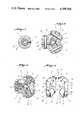
- FIG. 1is a sectional view of the fixed-arm embodiment of the invention.
- FIG. 2is a sectional view of the expandable-arm embodiment of the invention, in a retracted and an open position (open position indicated with dotted lines).
- FIG. 3is a cross-sectional view of the expandable-arm embodiment of the invention taken along the line 3--3.
- FIG. 4is a cross-sectional view of the expandable-arm embodiment of the invention taken along the line 4--4.
- FIG. 5is a cross-sectional view of the expandable-arm embodiment of the invention taken along the line 5--5.
- FIG. 6is a perspective view of the cutting arms of the invention.
- FIG. 1there is shown a well bore enlarger 10 which is the fixed-arm embodiment of the present invention.
- Well bore enlarger 10comprises a tubular housing member 12 which is adaptable for connection to a drill string or the like (not shown).
- the tubular housing member 12may be in one section as illustrated in FIG. 1, or may be made up of multiple sections as illustrated in FIG. 2.
- Tubular housing member 12is preferably machined from a solid "4142" grade steel forging.
- Tubular housing member 12has an enlarged section 14 with a diameter substantially the same as the diameter of the well bore 16 to be enlarged.
- the enlarged sectionhas a plurality of longitudinal cut-out portions 18, best seen in FIGS. 4 and 5, such cut-out portions extending along the entire length of the enlarged section 14.
- the cutoutsserve as a passageway for fluid traveling up the well bore between the well bore wall and the enlarged section.
- enlarged section 14has three cut-out portions disposed substantially 120° apart.
- the cut-out portions 18define blades 20 of the enlarged section 14 therebetween.
- the arc of the outer circumference of the cut-out portion 18measures substantially less than the arc of the outer circumference of blade 20, allowing blade 20 to be as wide as possible for greater strength and stability.
- Blade 20contains a longitudinal slot 22.
- the length of slot 22is less than the length of the enlarged section 14 and is positioned within the enlarged section such that a guide section 24 of each blade, which is circumferentially unbroken by the opening of slot 22, enters the well bore prior to enlargement of the well bore 16.
- this guide sectionis coated with hard facing such as tungsten carbide slugs to protect the tool from formation wear.
- Cutting arm 26is attached to blade 20 in slot 22.
- the preferred means of attachment to blade 20is via pins 28 extending through holes 30 in blade 20 and holes 32 in cutting arm 26.
- the pinsare held in place by snap rings.
- Cutting arm 26is configured to have an inner edge 34, an outer edge 36 and cutting edges 38.
- Cutting arm 26has two essentially parallel faces, leading face 37 and trailing face 39. The leading and trailing faces are essentially of polygonal configuration.
- the configuration of cutting edges 38is such that cutting arm 26 contains a fluid gallery 40 between the cutting edges, which is substantially perpendicular to the well bore wall.
- Cutting arm 26is attached to blade 20 so that inner edge 36 is essentially within the outer diameter of the enlarged section.
- inner edge 36abuts against tubular housing member 12.
- Cutting arm 26is preferably machined from "4142" grade steel in one piece.
- Synthetic diamond materialpreferably in the form of wafers 42, is attached to cutting arm 26.
- Wafers 42may be attached to cutting edges 38, or preferably to the inner cutting face 44 located within fluid gallery 40 and leading cutting face 45 located on leading face 37 of each cutting arm, near cutting edges 38.
- Tubular housing member 12is formed with a longitudinal bore 46 therethrough for the passage of fluid.
- ports 52which allow fluid from bore 46 to communicate with slot 22.
- nozzles 54which control the pressure and direction of the fluid therethrough such that a jet stream of fluid is directed through fluid gallery 40 to cool and clean cutting edges 38 and to keep slot 22 free of debris.
- nozzles 54are positioned so as to direct fluid perpendicular to the well bore wall, attacking the planes of any sedimentary formation and aiding in breaking up such formation allowing for easier enlargement of the well bore.
- tubular housing member 12preferably comprises an upper tubular member 56 attached, preferably threadedly, to a main tubular member 58 attached, preferably threadedly, to a lower tubular member 60, with a longitudinal bore 46 therethrough.
- bore 46is not a fluid passageway.
- main tubular member 58houses enlarged section 14, which is formed, as previously described, with slots 22, blades 20 and cut-out portions 18.
- Cutting arm 26, as best seen in FIG. 6,is configured to have an inner edge 34, an outer edge 36 and cutting edges 38.
- Cutting arm 26has two essentially parallel faces, leading face 37 and trailing face 39.
- the leading and trailing facesare essentially of polygonal configuration.
- the configuration of cutting edges 38is such that cutting arm 26 contains a fluid gallery 40 between the cutting edges which, in the fully extended position of cutting arm 26, is substantially perpendicular to the well bore wall.
- cutting arm 26is pivotally mounted to blade 20 within slot 22.
- the attachmentis preferably made by pin 28 which extends through holes 30 in blade 20 and hole 32 in cutting arm 26.
- Pin 28 and holes 30 and 32are positioned so as to allow strong outward turning moments when the tool is enlarging the well bore.
- Cutting arm 26is configured so as to have a spur 62 projecting from its inner edge 34 at the top of cutting arm 26 towards bore 46.
- Cutting arm 26is movable between a radially retracted position, (Refer to X in FIG. 2) wherein arm 26 is disposed in slot 22 essentially within the outer diameter of enlarged section 14, and a radially extended position (refer to Y in FIG. 2), wherein inner edge 34 remains at all times essentially within the outer diameter of enlarged section 14 and cutting edges 38 are substantially outside the outer diameter of enlarged section 14.
- tubular drive member 64The movement of cutting arm 26 is accomplished by the movement of a tubular drive member 64 within bore 46 and slidably connected therewith.
- tubular drive member 64comprises piston 66, upper drive member 68, which is engaged by piston 66, middle drive member 70, threadably connected to upper drive member 68, and lower drive member 72, threadably connected to middle drive member 70.
- the upper drive member 68has a groove 74 adapted to engage spur 62 on cutting arm 26.
- well bore enlarger 10includes means for stopping the extension of cutter arm 26 to ensure that inner edge 34 of cutting arm 26 remains at all times essentially within the outer diameter of enlarged section 14 and that cutter arm 26 moves through only a small angle or arc.
- the angle of arc through which cutting arm 26 movesis less than 30°.
- stop meanscomprise stop pins 76 which extend through blade 20 to slidingly engage stop pin slots 78 in cutting arm 26.
- stop pin 76When cutting arm 26 is fully extended, stop pin 76 abuts against wall 80 of stop pin slot 78 which is positioned on cutting arm 26 so as to ensure that inner edge 34 of cutting arm 26 remains at all times essentially within the outer diameter of enlarged section 14 while cutting edges 38 remain essentially outside the outer diameter of enlarged section 14 causing the creation of strong outward turning moments which force cutting arm 26 to remain in the open position when the well bore is being enlarged.
- cutting arm 26is configured so as to have back-up stop means in case of failure of the stop pin 76.
- the back-up stop meanscomprise stop edge 82 of cutter arm 26, adjacent to outer edge 36. Under ordinary conditions, stop edge 82 does not contact blade 20.
- stop edge 82Upon failure of stop pin 76, stop edge 82 abuts against upper wall 84 of slot 22 within blade 20, precluding further extension of cutting arm 26 and ensuring that inner edge 34 of cutting arm 26 remains at all times essentially within the outer diameter of enlarged section 14.
- Stop edge 82is preferably located close to upper wall 84 when cutting arm 26 is fully extended, preventing entry of formation cuttings into slot 22 between stop edge 82 and upper wall 84.
- leading face 37 and trailing face 39are configured to have two plateaus.
- the high plateau 86is that section of leading face 37 and trailing face 39 which at all times remains essentially within the outer diameter of enlarged section 14.
- the thickness of cutting arm 26 at any point on high plateau 86is substantially the same as the width of slot 20, thus allowing for maximum strength of hinge pin 28.
- the lower plateau 88is that section of leading face 37 and trailing face 39 which extends outside of the outer diameter of enlarged section 14.
- the width of cutting arm 26 at any point on lower plateau 88is slightly less than the width of slot 22, thus allowing cutting arm 26 to move to its retracted position X even if the portion exposed to the well bore sustains some damage.
- tubular drive member 64contains longitudinal grooves 90, any one of which is slidingly engagable with orientation pin 92, best seen in FIG. 3.
- Orientation pin 92is preferably engaged in hole 94 by means of a snap ring, hole 94 extending through tubular housing member 12.
- Groves 90also function as fluid bypasses in the event of piston seal failure, to prevent fluid erosion within the tool.
- tubular drive member 64has a longitudinal fluid passageway 96 therethrough.
- ports 98which allow fluid from passageway 96 to communicate with slot 22.
- nozzle 100which controls the pressure and direction of fluid therethrough such that a jet stream of fluid is directed through fluid gallery 40 to cool and clean cutting edges 38 and to keep slot 22 free of debris.
- Inner cutting face 44is directly cooled by the jet stream of fluid through fluid gallery 40.
- Leading cutting face 45is cooled by the jet stream through conduction and by forward leakage of the fluid as well as by fluid moving up the well bore through cut-out portions 18.
- ports 98are within middle drive member 70 and are positioned thereon so as to ensure that nozzles 100 direct fluid to fluid gallery 40 when the arms are in their fully extended position.
- nozzles 100are positioned so as to direct fluid perpendicular to the well bore wall, attacking the planes of any sedimentary formation and aiding in breaking up such formation, allowing for easier enlargement of the well bore.
- the number of grooves 90 in tubular drive member 64corresponds to the number of cutting arms 26 and are preferably oriented so as to position ports 98 such that fluid is directed into slot 22.
- Tubular drive member 64is resiliently biased upwardly by a bias element, preferably spring 102, which is set against a cap ring and split ring assembly 104 slidably attached to lower drive member 72 and bearing against a shoulder 106 of tubular housing member 12 where bore 46 narrows.
- spring 102Upon downward movement of tubular drive member 64, the upper end of spring 102 is engaged by the lower end of middle drive member 70.
- the maximum downward movement of tubular drive member 64is controlled by stop pin 76 and stop pin slot 78 and downward movement ceases when cutter arms 28 are in their fully extended position.
- Fluidcontinues to flow through passageway 96 and out of well bore enlarger 10 through a decreased diameter passageway 108 which can be further reduced by attachment of nozzle 110, maintaining a pressure differential across the tool for the operation of open-ended systems below well bore enlarger 10.
- nozzle 110By controlling the size and ratio of nozzle 110 and nozzles 100, the pressure drop across the tool and the percent of flow of fluid to cutter arms 26 and downstream toward passageway 108 can be varied.
Landscapes
- Engineering & Computer Science (AREA)
- Life Sciences & Earth Sciences (AREA)
- Geology (AREA)
- Mining & Mineral Resources (AREA)
- Mechanical Engineering (AREA)
- Physics & Mathematics (AREA)
- Environmental & Geological Engineering (AREA)
- Fluid Mechanics (AREA)
- General Life Sciences & Earth Sciences (AREA)
- Geochemistry & Mineralogy (AREA)
- Processing Of Stones Or Stones Resemblance Materials (AREA)
Abstract
Description
Claims (16)
Priority Applications (4)
| Application Number | Priority Date | Filing Date | Title |
|---|---|---|---|
| US06/634,956US4589504A (en) | 1984-07-27 | 1984-07-27 | Well bore enlarger |
| DE8585305111TDE3566564D1 (en) | 1984-07-27 | 1985-07-18 | Hole opener |
| EP85305111AEP0176180B1 (en) | 1984-07-27 | 1985-07-18 | Hole opener |
| NO852975ANO169609C (en) | 1984-07-27 | 1985-07-26 | Borehole expansion tool |
Applications Claiming Priority (1)
| Application Number | Priority Date | Filing Date | Title |
|---|---|---|---|
| US06/634,956US4589504A (en) | 1984-07-27 | 1984-07-27 | Well bore enlarger |
Publications (1)
| Publication Number | Publication Date |
|---|---|
| US4589504Atrue US4589504A (en) | 1986-05-20 |
Family
ID=24545827
Family Applications (1)
| Application Number | Title | Priority Date | Filing Date |
|---|---|---|---|
| US06/634,956Expired - LifetimeUS4589504A (en) | 1984-07-27 | 1984-07-27 | Well bore enlarger |
Country Status (1)
| Country | Link |
|---|---|
| US (1) | US4589504A (en) |
Cited By (65)
| Publication number | Priority date | Publication date | Assignee | Title |
|---|---|---|---|---|
| US4709462A (en)* | 1986-08-04 | 1987-12-01 | Oil Patch Group, Inc. | Method for assembling a well drilling tool |
| US4846290A (en)* | 1986-03-13 | 1989-07-11 | Smith International, Inc. | Underreamer with revolving diamond cutter elements |
| US4976323A (en)* | 1989-06-30 | 1990-12-11 | Kitchens Richard A | Counterboring device for wells |
| US5060738A (en)* | 1990-09-20 | 1991-10-29 | Slimdril International, Inc. | Three-blade underreamer |
| US5086852A (en)* | 1990-08-27 | 1992-02-11 | Wada Ventures | Fluid flow control system for operating a down-hole tool |
| US5184687A (en)* | 1988-11-22 | 1993-02-09 | Abdrakhmanov Gabdrashit S | Well reamer |
| US5269384A (en)* | 1991-11-08 | 1993-12-14 | Cherrington Corporation | Method and apparatus for cleaning a bore hole |
| EP0506689B1 (en)* | 1989-12-19 | 1994-06-15 | Diamant Boart Stratabit S.A. | Drilling tool for widening a bore well |
| US5361859A (en)* | 1993-02-12 | 1994-11-08 | Baker Hughes Incorporated | Expandable gage bit for drilling and method of drilling |
| US5368114A (en)* | 1992-04-30 | 1994-11-29 | Tandberg; Geir | Under-reaming tool for boreholes |
| US5735359A (en)* | 1996-06-10 | 1998-04-07 | Weatherford/Lamb, Inc. | Wellbore cutting tool |
| US6070677A (en)* | 1997-12-02 | 2000-06-06 | I.D.A. Corporation | Method and apparatus for enhancing production from a wellbore hole |
| US6189631B1 (en) | 1998-11-12 | 2001-02-20 | Adel Sheshtawy | Drilling tool with extendable elements |
| US6378632B1 (en)* | 1998-10-30 | 2002-04-30 | Smith International, Inc. | Remotely operable hydraulic underreamer |
| WO2002097231A1 (en) | 2001-06-01 | 2002-12-05 | Italo De Luca | Expandable drilling tool |
| RU2209920C1 (en)* | 2002-09-25 | 2003-08-10 | Открытое акционерное общество "Промгаз" | Facility to expand bore hole |
| US20030183424A1 (en)* | 2000-04-25 | 2003-10-02 | Tulloch Rory Mccrae | Expandable bit |
| US20040060710A1 (en)* | 2002-09-27 | 2004-04-01 | Gregory Marshall | Internal pressure indicator and locking mechanism for a downhole tool |
| US20040065479A1 (en)* | 2002-10-04 | 2004-04-08 | Philippe Fanuel | Bore hole underreamer having extendible cutting arms |
| US20040084224A1 (en)* | 2001-03-12 | 2004-05-06 | Halliburton Energy Services, Inc. | Bore hole opener |
| US20040134687A1 (en)* | 2002-07-30 | 2004-07-15 | Radford Steven R. | Expandable reamer apparatus for enlarging boreholes while drilling and methods of use |
| US20040154836A1 (en)* | 2001-08-08 | 2004-08-12 | Hoffmaster Carl M. | Advanced expandable reaming tool |
| US20040188149A1 (en)* | 2003-03-26 | 2004-09-30 | Thigpen Gary M. | Drill out bi-center bit and method for using same |
| US6886633B2 (en) | 2002-10-04 | 2005-05-03 | Security Dbs Nv/Sa | Bore hole underreamer |
| US20050211470A1 (en)* | 2004-03-27 | 2005-09-29 | Schlumberger Technology Corporation | Bottom hole assembly |
| US20050241856A1 (en)* | 2004-04-21 | 2005-11-03 | Security Dbs Nv/Sa | Underreaming and stabilizing tool and method for its use |
| US20050274546A1 (en)* | 2004-06-09 | 2005-12-15 | Philippe Fanuel | Reaming and stabilization tool and method for its use in a borehole |
| US20070205022A1 (en)* | 2006-03-02 | 2007-09-06 | Baker Hughes Incorporated | Automated steerable hole enlargement drilling device and methods |
| US20080008540A1 (en)* | 2005-07-22 | 2008-01-10 | Soilmec S.P.A. | Method and device for mixing earth in situ for the formation of underground walls or diaphragms |
| US20080128169A1 (en)* | 2006-12-04 | 2008-06-05 | Radford Steven R | Restriction element trap for use with an actuation element of a downhole apparatus and method of use |
| US20090095532A1 (en)* | 2007-10-11 | 2009-04-16 | Smith International, Inc. | Self sharpening cutting structure for expandable earth boring apparatus using impregnated and matrix materials |
| US20100018779A1 (en)* | 2008-07-24 | 2010-01-28 | Smith International, Inc. | Placement of cutting elements on secondary cutting structures of drilling tool assemblies |
| US20100139981A1 (en)* | 2006-03-02 | 2010-06-10 | Baker Hughes Incorporated | Hole Enlargement Drilling Device and Methods for Using Same |
| US20110127044A1 (en)* | 2009-09-30 | 2011-06-02 | Baker Hughes Incorporated | Remotely controlled apparatus for downhole applications and methods of operation |
| WO2012021069A1 (en) | 2010-08-12 | 2012-02-16 | Sinvent As | Cutting tool integrated in a drillstring |
| US20120193147A1 (en)* | 2011-01-28 | 2012-08-02 | Hall David R | Fluid Path between the Outer Surface of a Tool and an Expandable Blade |
| US8657038B2 (en) | 2009-07-13 | 2014-02-25 | Baker Hughes Incorporated | Expandable reamer apparatus including stabilizers |
| US8746371B2 (en) | 2009-09-30 | 2014-06-10 | Baker Hughes Incorporated | Downhole tools having activation members for moving movable bodies thereof and methods of using such tools |
| US8844635B2 (en) | 2011-05-26 | 2014-09-30 | Baker Hughes Incorporated | Corrodible triggering elements for use with subterranean borehole tools having expandable members and related methods |
| US8939236B2 (en) | 2010-10-04 | 2015-01-27 | Baker Hughes Incorporated | Status indicators for use in earth-boring tools having expandable members and methods of making and using such status indicators and earth-boring tools |
| US8960333B2 (en) | 2011-12-15 | 2015-02-24 | Baker Hughes Incorporated | Selectively actuating expandable reamers and related methods |
| US9038748B2 (en) | 2010-11-08 | 2015-05-26 | Baker Hughes Incorporated | Tools for use in subterranean boreholes having expandable members and related methods |
| US20150144405A1 (en)* | 2013-11-25 | 2015-05-28 | Smith International, Inc. | Cutter block for a downhole underreamer |
| US9051792B2 (en) | 2010-07-21 | 2015-06-09 | Baker Hughes Incorporated | Wellbore tool with exchangeable blades |
| US9068407B2 (en) | 2012-05-03 | 2015-06-30 | Baker Hughes Incorporated | Drilling assemblies including expandable reamers and expandable stabilizers, and related methods |
| US9175520B2 (en) | 2009-09-30 | 2015-11-03 | Baker Hughes Incorporated | Remotely controlled apparatus for downhole applications, components for such apparatus, remote status indication devices for such apparatus, and related methods |
| US9187960B2 (en) | 2006-12-04 | 2015-11-17 | Baker Hughes Incorporated | Expandable reamer tools |
| US9267331B2 (en) | 2011-12-15 | 2016-02-23 | Baker Hughes Incorporated | Expandable reamers and methods of using expandable reamers |
| US9284816B2 (en) | 2013-03-04 | 2016-03-15 | Baker Hughes Incorporated | Actuation assemblies, hydraulically actuated tools for use in subterranean boreholes including actuation assemblies and related methods |
| US9290998B2 (en) | 2013-02-25 | 2016-03-22 | Baker Hughes Incorporated | Actuation mechanisms for downhole assemblies and related downhole assemblies and methods |
| US9341027B2 (en) | 2013-03-04 | 2016-05-17 | Baker Hughes Incorporated | Expandable reamer assemblies, bottom-hole assemblies, and related methods |
| US9388638B2 (en) | 2012-03-30 | 2016-07-12 | Baker Hughes Incorporated | Expandable reamers having sliding and rotating expandable blades, and related methods |
| US9394746B2 (en) | 2012-05-16 | 2016-07-19 | Baker Hughes Incorporated | Utilization of expandable reamer blades in rigid earth-boring tool bodies |
| US9493991B2 (en) | 2012-04-02 | 2016-11-15 | Baker Hughes Incorporated | Cutting structures, tools for use in subterranean boreholes including cutting structures and related methods |
| WO2016186516A1 (en) | 2015-05-19 | 2016-11-24 | Sintef Tto As | Milling tool with self driven active side cutters |
| US9677344B2 (en) | 2013-03-01 | 2017-06-13 | Baker Hughes Incorporated | Components of drilling assemblies, drilling assemblies, and methods of stabilizing drilling assemblies in wellbores in subterranean formations |
| CN108868617A (en)* | 2018-07-13 | 2018-11-23 | 北京市华清地热开发集团有限公司 | Circular hole drilling tool |
| US10174560B2 (en) | 2015-08-14 | 2019-01-08 | Baker Hughes Incorporated | Modular earth-boring tools, modules for such tools and related methods |
| US20200232294A1 (en)* | 2015-09-15 | 2020-07-23 | Abrado, Inc. | Downhole Tubular Milling Apparatus, Especially Suitable For Deployment on Coiled Tubing |
| US10914122B2 (en)* | 2018-05-30 | 2021-02-09 | Henan Polytechnic University | Liquid injection type reamer bit |
| GB2597799A (en)* | 2020-08-07 | 2022-02-09 | Coretrax Tech Limited | Cleaning tool and method |
| US11261730B2 (en) | 2018-07-16 | 2022-03-01 | Saudi Arabian Oil Company | Wellbore failure analysis and assessment |
| US11499374B2 (en) | 2017-12-13 | 2022-11-15 | Nov Downhole Eurasia Limited | Downhole devices and associated apparatus and methods |
| US11954800B2 (en) | 2021-12-14 | 2024-04-09 | Saudi Arabian Oil Company | Converting borehole images into three dimensional structures for numerical modeling and simulation applications |
| US12372684B2 (en) | 2022-05-24 | 2025-07-29 | Saudi Arabian Oil Company | Numerical simulation capability for determining blockages within a wellbore and wellbore completion setups |
Citations (13)
| Publication number | Priority date | Publication date | Assignee | Title |
|---|---|---|---|---|
| NL111878C (en)* | ||||
| US1485249A (en)* | 1921-11-21 | 1924-02-26 | Joseph H Thatcher | Underreamer |
| US2069482A (en)* | 1935-04-18 | 1937-02-02 | James I Seay | Well reamer |
| US2344598A (en)* | 1942-01-06 | 1944-03-21 | Walter L Church | Wall scraper and well logging tool |
| US2859943A (en)* | 1957-01-07 | 1958-11-11 | Chadderdon Jack | Expansible mill for well casings |
| US3171503A (en)* | 1962-05-02 | 1965-03-02 | Kirk R Shirley | Expansible rotary drill bit |
| US3208540A (en)* | 1963-03-21 | 1965-09-28 | Baker Oil Tools Inc | Expansible rotary well drilling bit |
| US3237705A (en)* | 1963-11-13 | 1966-03-01 | Williams Joseph W | Reamer for enlarging and straightening bore holes |
| US3749187A (en)* | 1972-05-08 | 1973-07-31 | Grant Oil Tool Co | Underreamer having variable arm extension |
| US3757877A (en)* | 1971-12-30 | 1973-09-11 | Grant Oil Tool Co | Large diameter hole opener for earth boring |
| US3894590A (en)* | 1972-10-16 | 1975-07-15 | Sumitomo Metal Mining Co Limit | Drilling system |
| US4282941A (en)* | 1979-04-18 | 1981-08-11 | Smith International Inc. | Underreamer with large cutter elements and axial fluid passage |
| US4431065A (en)* | 1982-02-26 | 1984-02-14 | Smith International, Inc. | Underreamer |
- 1984
- 1984-07-27USUS06/634,956patent/US4589504A/ennot_activeExpired - Lifetime
Patent Citations (13)
| Publication number | Priority date | Publication date | Assignee | Title |
|---|---|---|---|---|
| NL111878C (en)* | ||||
| US1485249A (en)* | 1921-11-21 | 1924-02-26 | Joseph H Thatcher | Underreamer |
| US2069482A (en)* | 1935-04-18 | 1937-02-02 | James I Seay | Well reamer |
| US2344598A (en)* | 1942-01-06 | 1944-03-21 | Walter L Church | Wall scraper and well logging tool |
| US2859943A (en)* | 1957-01-07 | 1958-11-11 | Chadderdon Jack | Expansible mill for well casings |
| US3171503A (en)* | 1962-05-02 | 1965-03-02 | Kirk R Shirley | Expansible rotary drill bit |
| US3208540A (en)* | 1963-03-21 | 1965-09-28 | Baker Oil Tools Inc | Expansible rotary well drilling bit |
| US3237705A (en)* | 1963-11-13 | 1966-03-01 | Williams Joseph W | Reamer for enlarging and straightening bore holes |
| US3757877A (en)* | 1971-12-30 | 1973-09-11 | Grant Oil Tool Co | Large diameter hole opener for earth boring |
| US3749187A (en)* | 1972-05-08 | 1973-07-31 | Grant Oil Tool Co | Underreamer having variable arm extension |
| US3894590A (en)* | 1972-10-16 | 1975-07-15 | Sumitomo Metal Mining Co Limit | Drilling system |
| US4282941A (en)* | 1979-04-18 | 1981-08-11 | Smith International Inc. | Underreamer with large cutter elements and axial fluid passage |
| US4431065A (en)* | 1982-02-26 | 1984-02-14 | Smith International, Inc. | Underreamer |
Non-Patent Citations (24)
| Title |
|---|
| A 1 1982 83 Catalog Expandable Underreamer.* |
| A Z 1982 83 Catalog Hard Rock Underreamer, Rock Bit Underreamer, Dual Rock Type Underreamer, Section Mill.* |
| A-1 1982-83 Catalog--Expandable Underreamer. |
| A-Z 1982-83 Catalog--Hard Rock Underreamer, Rock Bit Underreamer, Dual Rock Type Underreamer, Section Mill. |
| Baker 1974 75 Catalog Lockomatic Expanding Hole Opener.* |
| Baker 1974-75 Catalog--Lockomatic Expanding Hole Opener. |
| Drilling & Service, 1982 83 Catalog Diamond Underreamer.* |
| Drilling & Service, 1982-83 Catalog--Diamond Underreamer. |
| Eureka 1962 63 Catalog Swan Underreamers.* |
| Eureka 1962-63 Catalog-Swan Underreamers. |
| Grant 1982 83 Catalog Blade Wall Scraper, Rock Bit Underreamer, Hole Enlarger.* |
| Grant 1982-83 Catalog--Blade Wall Scraper, Rock Bit Underreamer, Hole Enlarger. |
| Industrialexport 1974 75 Catalog Rock Bit Underreamers.* |
| Industrialexport 1974-75 Catalog--Rock Bit Underreamers. |
| Lor 1982 83 Catalog Rock Type Underreamer, Drilling Type Underreamer.* |
| Lor 1982-83 Catalog--Rock-Type Underreamer, Drilling-Type Underreamer. |
| Servco 1968 69 Catalog Section Mill/Casing Cutter, Rock Type Hole Opener, Rock Crilling Hole Opener.* |
| Servco 1968-69 Catalog--Section Mill/Casing Cutter, Rock-Type Hole Opener, Rock Crilling-Hole Opener. |
| Servco 1982 83 Catalog Rock Type Underreamer, Drilling Type Underreamer, Two Stage Underreamer.* |
| Servco 1982-83 Catalog--Rock-Type Underreamer, Drilling-Type Underreamer, Two-Stage Underreamer. |
| Topservices, 1982 83 Catalog Hole Openers and Underreamers.* |
| Topservices, 1982-83 Catalog--Hole Openers and Underreamers. |
| Tri State 1982 83 Catalog Lockomatic Expanding Hole Opener, Fixed Hole Opener, Section Mill.* |
| Tri-State 1982-83 Catalog--Lockomatic Expanding Hole Opener, Fixed Hole Opener, Section Mill. |
Cited By (131)
| Publication number | Priority date | Publication date | Assignee | Title |
|---|---|---|---|---|
| US4846290A (en)* | 1986-03-13 | 1989-07-11 | Smith International, Inc. | Underreamer with revolving diamond cutter elements |
| US4709462A (en)* | 1986-08-04 | 1987-12-01 | Oil Patch Group, Inc. | Method for assembling a well drilling tool |
| US5184687A (en)* | 1988-11-22 | 1993-02-09 | Abdrakhmanov Gabdrashit S | Well reamer |
| US4976323A (en)* | 1989-06-30 | 1990-12-11 | Kitchens Richard A | Counterboring device for wells |
| EP0506689B1 (en)* | 1989-12-19 | 1994-06-15 | Diamant Boart Stratabit S.A. | Drilling tool for widening a bore well |
| US5341888A (en)* | 1989-12-19 | 1994-08-30 | Diamant Boart Stratabit S.A. | Drilling tool intended to widen a well |
| US5086852A (en)* | 1990-08-27 | 1992-02-11 | Wada Ventures | Fluid flow control system for operating a down-hole tool |
| US5060738A (en)* | 1990-09-20 | 1991-10-29 | Slimdril International, Inc. | Three-blade underreamer |
| US5269384A (en)* | 1991-11-08 | 1993-12-14 | Cherrington Corporation | Method and apparatus for cleaning a bore hole |
| US5368114A (en)* | 1992-04-30 | 1994-11-29 | Tandberg; Geir | Under-reaming tool for boreholes |
| US5361859A (en)* | 1993-02-12 | 1994-11-08 | Baker Hughes Incorporated | Expandable gage bit for drilling and method of drilling |
| US5735359A (en)* | 1996-06-10 | 1998-04-07 | Weatherford/Lamb, Inc. | Wellbore cutting tool |
| US6070677A (en)* | 1997-12-02 | 2000-06-06 | I.D.A. Corporation | Method and apparatus for enhancing production from a wellbore hole |
| US6378632B1 (en)* | 1998-10-30 | 2002-04-30 | Smith International, Inc. | Remotely operable hydraulic underreamer |
| US6189631B1 (en) | 1998-11-12 | 2001-02-20 | Adel Sheshtawy | Drilling tool with extendable elements |
| US20030183424A1 (en)* | 2000-04-25 | 2003-10-02 | Tulloch Rory Mccrae | Expandable bit |
| US7293616B2 (en)* | 2000-04-25 | 2007-11-13 | Weatherford/Lamb, Inc. | Expandable bit |
| US20040084224A1 (en)* | 2001-03-12 | 2004-05-06 | Halliburton Energy Services, Inc. | Bore hole opener |
| WO2002097231A1 (en) | 2001-06-01 | 2002-12-05 | Italo De Luca | Expandable drilling tool |
| US20040206547A1 (en)* | 2001-06-01 | 2004-10-21 | De Luca Italo | Expandable drilling tool |
| US7195080B2 (en) | 2001-06-01 | 2007-03-27 | De Luca Italo | Expandable drilling tool and method |
| US7451837B2 (en)* | 2001-08-08 | 2008-11-18 | Smith International, Inc. | Advanced expandable reaming tool |
| US20040154836A1 (en)* | 2001-08-08 | 2004-08-12 | Hoffmaster Carl M. | Advanced expandable reaming tool |
| US20040159468A1 (en)* | 2001-08-08 | 2004-08-19 | Hoffmaster Carl M. | Advanced expandable reaming tool |
| US6880650B2 (en)* | 2001-08-08 | 2005-04-19 | Smith International, Inc. | Advanced expandable reaming tool |
| US20080105464A1 (en)* | 2002-07-30 | 2008-05-08 | Baker Hughes Incorporated | Moveable blades and bearing pads |
| US8047304B2 (en) | 2002-07-30 | 2011-11-01 | Baker Hughes Incorporated | Expandable reamer for subterranean boreholes and methods of use |
| US7681666B2 (en) | 2002-07-30 | 2010-03-23 | Baker Hughes Incorporated | Expandable reamer for subterranean boreholes and methods of use |
| US20100276199A1 (en)* | 2002-07-30 | 2010-11-04 | Baker Hughes Incorporated | Expandable reamer apparatus |
| US20100288557A1 (en)* | 2002-07-30 | 2010-11-18 | Baker Hughes Incorporated | Expandable reamer for subterranean boreholes and methods of use |
| US7594552B2 (en) | 2002-07-30 | 2009-09-29 | Baker Hughes Incorporated | Expandable reamer apparatus for enlarging boreholes while drilling |
| US7549485B2 (en) | 2002-07-30 | 2009-06-23 | Baker Hughes Incorporated | Expandable reamer apparatus for enlarging subterranean boreholes and methods of use |
| US8020635B2 (en) | 2002-07-30 | 2011-09-20 | Baker Hughes Incorporated | Expandable reamer apparatus |
| US10087683B2 (en) | 2002-07-30 | 2018-10-02 | Baker Hughes Oilfield Operations Llc | Expandable apparatus and related methods |
| US7036611B2 (en) | 2002-07-30 | 2006-05-02 | Baker Hughes Incorporated | Expandable reamer apparatus for enlarging boreholes while drilling and methods of use |
| US20070017708A1 (en)* | 2002-07-30 | 2007-01-25 | Radford Steven R | Expandable reamer apparatus for enlarging boreholes while drilling and methods of use |
| US20040134687A1 (en)* | 2002-07-30 | 2004-07-15 | Radford Steven R. | Expandable reamer apparatus for enlarging boreholes while drilling and methods of use |
| US9611697B2 (en) | 2002-07-30 | 2017-04-04 | Baker Hughes Oilfield Operations, Inc. | Expandable apparatus and related methods |
| US8196679B2 (en) | 2002-07-30 | 2012-06-12 | Baker Hughes Incorporated | Expandable reamers for subterranean drilling and related methods |
| US7308937B2 (en) | 2002-07-30 | 2007-12-18 | Baker Hughes Incorporated | Expandable reamer apparatus for enlarging boreholes while drilling and methods of use |
| US8215418B2 (en) | 2002-07-30 | 2012-07-10 | Baker Hughes Incorporated | Expandable reamer apparatus and related methods |
| US8813871B2 (en) | 2002-07-30 | 2014-08-26 | Baker Hughes Incorporated | Expandable apparatus and related methods |
| US7721823B2 (en) | 2002-07-30 | 2010-05-25 | Baker Hughes Incorporated | Moveable blades and bearing pads |
| US20080105465A1 (en)* | 2002-07-30 | 2008-05-08 | Baker Hughes Incorporated | Expandable reamer for subterranean boreholes and methods of use |
| US20080110678A1 (en)* | 2002-07-30 | 2008-05-15 | Baker Hughes Incorporated | Expandable reamer apparatus for enlarging boreholes while drilling |
| RU2209920C1 (en)* | 2002-09-25 | 2003-08-10 | Открытое акционерное общество "Промгаз" | Facility to expand bore hole |
| US6851491B2 (en)* | 2002-09-27 | 2005-02-08 | Weatherford/Lamb, Inc. | Internal pressure indicator and locking mechanism for a downhole tool |
| US20040060710A1 (en)* | 2002-09-27 | 2004-04-01 | Gregory Marshall | Internal pressure indicator and locking mechanism for a downhole tool |
| US20040065479A1 (en)* | 2002-10-04 | 2004-04-08 | Philippe Fanuel | Bore hole underreamer having extendible cutting arms |
| US6929076B2 (en) | 2002-10-04 | 2005-08-16 | Security Dbs Nv/Sa | Bore hole underreamer having extendible cutting arms |
| US6886633B2 (en) | 2002-10-04 | 2005-05-03 | Security Dbs Nv/Sa | Bore hole underreamer |
| US6926099B2 (en) | 2003-03-26 | 2005-08-09 | Varel International, L.P. | Drill out bi-center bit and method for using same |
| US20040188149A1 (en)* | 2003-03-26 | 2004-09-30 | Thigpen Gary M. | Drill out bi-center bit and method for using same |
| US7316277B2 (en) | 2004-03-27 | 2008-01-08 | Schlumberger Technology Corporation | Bottom hole assembly |
| US20050211470A1 (en)* | 2004-03-27 | 2005-09-29 | Schlumberger Technology Corporation | Bottom hole assembly |
| US20050241856A1 (en)* | 2004-04-21 | 2005-11-03 | Security Dbs Nv/Sa | Underreaming and stabilizing tool and method for its use |
| US7658241B2 (en) | 2004-04-21 | 2010-02-09 | Security Dbs Nv/Sa | Underreaming and stabilizing tool and method for its use |
| US7975783B2 (en) | 2004-06-09 | 2011-07-12 | Halliburton Energy Services, Inc. | Reaming and stabilization tool and method for its use in a borehole |
| US7584811B2 (en) | 2004-06-09 | 2009-09-08 | Security Dbs Nv/Sa | Reaming and stabilization tool and method for its use in a borehole |
| US20050274546A1 (en)* | 2004-06-09 | 2005-12-15 | Philippe Fanuel | Reaming and stabilization tool and method for its use in a borehole |
| US20090314548A1 (en)* | 2004-06-09 | 2009-12-24 | Philippe Fanuel | Reaming and Stabilization Tool and Method for its Use in a Borehole |
| US7401666B2 (en) | 2004-06-09 | 2008-07-22 | Security Dbs Nv/Sa | Reaming and stabilization tool and method for its use in a borehole |
| US20080257608A1 (en)* | 2004-06-09 | 2008-10-23 | Philippe Fanuel | Reaming and stabilization tool and method for its use in a borehole |
| US8112911B2 (en)* | 2005-07-22 | 2012-02-14 | SOILMEC, S.p.A | Method and device for mixing earth in situ for the formation of underground walls or diaphragms |
| US20080008540A1 (en)* | 2005-07-22 | 2008-01-10 | Soilmec S.P.A. | Method and device for mixing earth in situ for the formation of underground walls or diaphragms |
| US8875810B2 (en) | 2006-03-02 | 2014-11-04 | Baker Hughes Incorporated | Hole enlargement drilling device and methods for using same |
| US9187959B2 (en) | 2006-03-02 | 2015-11-17 | Baker Hughes Incorporated | Automated steerable hole enlargement drilling device and methods |
| US9482054B2 (en) | 2006-03-02 | 2016-11-01 | Baker Hughes Incorporated | Hole enlargement drilling device and methods for using same |
| US20070205022A1 (en)* | 2006-03-02 | 2007-09-06 | Baker Hughes Incorporated | Automated steerable hole enlargement drilling device and methods |
| US20100139981A1 (en)* | 2006-03-02 | 2010-06-10 | Baker Hughes Incorporated | Hole Enlargement Drilling Device and Methods for Using Same |
| US8657039B2 (en) | 2006-12-04 | 2014-02-25 | Baker Hughes Incorporated | Restriction element trap for use with an actuation element of a downhole apparatus and method of use |
| US20080128169A1 (en)* | 2006-12-04 | 2008-06-05 | Radford Steven R | Restriction element trap for use with an actuation element of a downhole apparatus and method of use |
| US9187960B2 (en) | 2006-12-04 | 2015-11-17 | Baker Hughes Incorporated | Expandable reamer tools |
| US7963348B2 (en)* | 2007-10-11 | 2011-06-21 | Smith International, Inc. | Expandable earth boring apparatus using impregnated and matrix materials for enlarging a borehole |
| US20090095532A1 (en)* | 2007-10-11 | 2009-04-16 | Smith International, Inc. | Self sharpening cutting structure for expandable earth boring apparatus using impregnated and matrix materials |
| GB2461984B (en)* | 2008-07-24 | 2012-12-26 | Smith International | Placement of cutting elements on secondary cutting structures of drilling tool assemblies |
| US7954564B2 (en)* | 2008-07-24 | 2011-06-07 | Smith International, Inc. | Placement of cutting elements on secondary cutting structures of drilling tool assemblies |
| US20100018779A1 (en)* | 2008-07-24 | 2010-01-28 | Smith International, Inc. | Placement of cutting elements on secondary cutting structures of drilling tool assemblies |
| US8657038B2 (en) | 2009-07-13 | 2014-02-25 | Baker Hughes Incorporated | Expandable reamer apparatus including stabilizers |
| US8881833B2 (en) | 2009-09-30 | 2014-11-11 | Baker Hughes Incorporated | Remotely controlled apparatus for downhole applications and methods of operation |
| US20110127044A1 (en)* | 2009-09-30 | 2011-06-02 | Baker Hughes Incorporated | Remotely controlled apparatus for downhole applications and methods of operation |
| US9719304B2 (en) | 2009-09-30 | 2017-08-01 | Baker Hughes Oilfield Operations Llc | Remotely controlled apparatus for downhole applications and methods of operation |
| US8746371B2 (en) | 2009-09-30 | 2014-06-10 | Baker Hughes Incorporated | Downhole tools having activation members for moving movable bodies thereof and methods of using such tools |
| US9175520B2 (en) | 2009-09-30 | 2015-11-03 | Baker Hughes Incorporated | Remotely controlled apparatus for downhole applications, components for such apparatus, remote status indication devices for such apparatus, and related methods |
| US10472908B2 (en) | 2009-09-30 | 2019-11-12 | Baker Hughes Oilfield Operations Llc | Remotely controlled apparatus for downhole applications and methods of operation |
| US9051792B2 (en) | 2010-07-21 | 2015-06-09 | Baker Hughes Incorporated | Wellbore tool with exchangeable blades |
| WO2012021069A1 (en) | 2010-08-12 | 2012-02-16 | Sinvent As | Cutting tool integrated in a drillstring |
| US8789624B2 (en) | 2010-08-12 | 2014-07-29 | Sinvent As | Cutting tool integrated in a drillstring |
| US8939236B2 (en) | 2010-10-04 | 2015-01-27 | Baker Hughes Incorporated | Status indicators for use in earth-boring tools having expandable members and methods of making and using such status indicators and earth-boring tools |
| US9725958B2 (en) | 2010-10-04 | 2017-08-08 | Baker Hughes Incorporated | Earth-boring tools including expandable members and status indicators and methods of making and using such earth-boring tools |
| US9038748B2 (en) | 2010-11-08 | 2015-05-26 | Baker Hughes Incorporated | Tools for use in subterranean boreholes having expandable members and related methods |
| US20120193147A1 (en)* | 2011-01-28 | 2012-08-02 | Hall David R | Fluid Path between the Outer Surface of a Tool and an Expandable Blade |
| US8844635B2 (en) | 2011-05-26 | 2014-09-30 | Baker Hughes Incorporated | Corrodible triggering elements for use with subterranean borehole tools having expandable members and related methods |
| US9677355B2 (en) | 2011-05-26 | 2017-06-13 | Baker Hughes Incorporated | Corrodible triggering elements for use with subterranean borehole tools having expandable members and related methods |
| US10576544B2 (en) | 2011-05-26 | 2020-03-03 | Baker Hughes, A Ge Company, Llc | Methods of forming triggering elements for expandable apparatus for use in subterranean boreholes |
| US9759013B2 (en) | 2011-12-15 | 2017-09-12 | Baker Hughes Incorporated | Selectively actuating expandable reamers and related methods |
| US9267331B2 (en) | 2011-12-15 | 2016-02-23 | Baker Hughes Incorporated | Expandable reamers and methods of using expandable reamers |
| US9719305B2 (en) | 2011-12-15 | 2017-08-01 | Baker Hughes Incorporated | Expandable reamers and methods of using expandable reamers |
| US8960333B2 (en) | 2011-12-15 | 2015-02-24 | Baker Hughes Incorporated | Selectively actuating expandable reamers and related methods |
| US9388638B2 (en) | 2012-03-30 | 2016-07-12 | Baker Hughes Incorporated | Expandable reamers having sliding and rotating expandable blades, and related methods |
| US9745800B2 (en) | 2012-03-30 | 2017-08-29 | Baker Hughes Incorporated | Expandable reamers having nonlinearly expandable blades, and related methods |
| US9493991B2 (en) | 2012-04-02 | 2016-11-15 | Baker Hughes Incorporated | Cutting structures, tools for use in subterranean boreholes including cutting structures and related methods |
| US9885213B2 (en) | 2012-04-02 | 2018-02-06 | Baker Hughes Incorporated | Cutting structures, tools for use in subterranean boreholes including cutting structures and related methods |
| US9068407B2 (en) | 2012-05-03 | 2015-06-30 | Baker Hughes Incorporated | Drilling assemblies including expandable reamers and expandable stabilizers, and related methods |
| US9394746B2 (en) | 2012-05-16 | 2016-07-19 | Baker Hughes Incorporated | Utilization of expandable reamer blades in rigid earth-boring tool bodies |
| US10047563B2 (en) | 2012-05-16 | 2018-08-14 | Baker Hughes Incorporated | Methods of forming earth-boring tools utilizing expandable reamer blades |
| US10006272B2 (en) | 2013-02-25 | 2018-06-26 | Baker Hughes Incorporated | Actuation mechanisms for downhole assemblies and related downhole assemblies and methods |
| US9290998B2 (en) | 2013-02-25 | 2016-03-22 | Baker Hughes Incorporated | Actuation mechanisms for downhole assemblies and related downhole assemblies and methods |
| US9677344B2 (en) | 2013-03-01 | 2017-06-13 | Baker Hughes Incorporated | Components of drilling assemblies, drilling assemblies, and methods of stabilizing drilling assemblies in wellbores in subterranean formations |
| US9284816B2 (en) | 2013-03-04 | 2016-03-15 | Baker Hughes Incorporated | Actuation assemblies, hydraulically actuated tools for use in subterranean boreholes including actuation assemblies and related methods |
| US9341027B2 (en) | 2013-03-04 | 2016-05-17 | Baker Hughes Incorporated | Expandable reamer assemblies, bottom-hole assemblies, and related methods |
| US10018014B2 (en) | 2013-03-04 | 2018-07-10 | Baker Hughes Incorporated | Actuation assemblies, hydraulically actuated tools for use in subterranean boreholes including actuation assemblies and related methods |
| US10036206B2 (en) | 2013-03-04 | 2018-07-31 | Baker Hughes Incorporated | Expandable reamer assemblies, bottom hole assemblies, and related methods |
| US10480251B2 (en) | 2013-03-04 | 2019-11-19 | Baker Hughes, A Ge Company, Llc | Expandable downhole tool assemblies, bottom-hole assemblies, and related methods |
| US20150144405A1 (en)* | 2013-11-25 | 2015-05-28 | Smith International, Inc. | Cutter block for a downhole underreamer |
| WO2016186516A1 (en) | 2015-05-19 | 2016-11-24 | Sintef Tto As | Milling tool with self driven active side cutters |
| US10829998B2 (en) | 2015-08-14 | 2020-11-10 | Baker Hughes, A Ge Company, Llc | Modular earth-boring tools, modules for such tools and related methods |
| US10174560B2 (en) | 2015-08-14 | 2019-01-08 | Baker Hughes Incorporated | Modular earth-boring tools, modules for such tools and related methods |
| US11708735B2 (en) | 2015-09-15 | 2023-07-25 | Abrado, Inc. | Downhole tubular milling apparatus, especially suitable for deployment on coiled tubing |
| US20200232294A1 (en)* | 2015-09-15 | 2020-07-23 | Abrado, Inc. | Downhole Tubular Milling Apparatus, Especially Suitable For Deployment on Coiled Tubing |
| US10989005B2 (en)* | 2015-09-15 | 2021-04-27 | Abrado, Inc. | Downhole tubular milling apparatus, especially suitable for deployment on coiled tubing |
| US11441378B2 (en)* | 2015-09-15 | 2022-09-13 | Abrado, Inc. | Downhole tubular milling apparatus, especially suitable for deployment on coiled tubing |
| US11499374B2 (en) | 2017-12-13 | 2022-11-15 | Nov Downhole Eurasia Limited | Downhole devices and associated apparatus and methods |
| US10914122B2 (en)* | 2018-05-30 | 2021-02-09 | Henan Polytechnic University | Liquid injection type reamer bit |
| CN108868617A (en)* | 2018-07-13 | 2018-11-23 | 北京市华清地热开发集团有限公司 | Circular hole drilling tool |
| CN108868617B (en)* | 2018-07-13 | 2024-06-04 | 北京市华清地热开发集团有限公司 | Round hole drilling tool |
| US11261730B2 (en) | 2018-07-16 | 2022-03-01 | Saudi Arabian Oil Company | Wellbore failure analysis and assessment |
| GB2597799A (en)* | 2020-08-07 | 2022-02-09 | Coretrax Tech Limited | Cleaning tool and method |
| US12110766B2 (en) | 2020-08-07 | 2024-10-08 | Coretrax Globl Limited | Downhole cleaning tool and method |
| US11954800B2 (en) | 2021-12-14 | 2024-04-09 | Saudi Arabian Oil Company | Converting borehole images into three dimensional structures for numerical modeling and simulation applications |
| US12372684B2 (en) | 2022-05-24 | 2025-07-29 | Saudi Arabian Oil Company | Numerical simulation capability for determining blockages within a wellbore and wellbore completion setups |
Similar Documents
| Publication | Publication Date | Title |
|---|---|---|
| US4589504A (en) | Well bore enlarger | |
| CA1238631A (en) | Well bore enlarger | |
| US7143847B2 (en) | Drilling apparatus | |
| US4431065A (en) | Underreamer | |
| US6378632B1 (en) | Remotely operable hydraulic underreamer | |
| US4401171A (en) | Underreamer with debris flushing flow path | |
| CA2257538C (en) | Cutting tool for use in a wellbore | |
| CA2219985C (en) | Cantilevered hole opener | |
| US6688410B1 (en) | Hydro-lifter rock bit with PDC inserts | |
| US4538690A (en) | PDC cutter and bit | |
| US6408958B1 (en) | Superabrasive cutting assemblies including cutters of varying orientations and drill bits so equipped | |
| US4887668A (en) | Cutting tool for cutting well casing | |
| US5074355A (en) | Section mill with multiple cutting blades | |
| GB2320270A (en) | Underreamer with extendable cutting blades | |
| US3220754A (en) | Replaceable drill bit nozzles | |
| US4784231A (en) | Extended drill bit nozzle having side discharge ports | |
| US5934394A (en) | Drill means | |
| US6264367B1 (en) | Dual-seal drill bit with fluid cleaning capability | |
| EP3698005B1 (en) | Underreamer | |
| US5363932A (en) | PDC drag bit with improved hydraulics | |
| US2238377A (en) | Undercutter | |
| US3949820A (en) | Underreamer cutter arm | |
| US4461361A (en) | Underreamer with cylindrical boss and socket hinge assembly for the cutter arm | |
| US2548931A (en) | Underreamer | |
| US4194578A (en) | Raise boring head with retractable gage cutters |
Legal Events
| Date | Code | Title | Description |
|---|---|---|---|
| AS | Assignment | Owner name:DIAMANT BOART SOCIETE ANONYME AVENUE DU PONT DE LU Free format text:ASSIGNMENT OF ASSIGNORS INTEREST.;ASSIGNOR:SIMPSON, NEIL A. A.;REEL/FRAME:004313/0107 Effective date:19840918 Owner name:DIAMANT BOART SOCIETE ANONYME A CORP. OF BELGIUM,B Free format text:ASSIGNMENT OF ASSIGNORS INTEREST;ASSIGNOR:SIMPSON, NEIL A. A.;REEL/FRAME:004313/0107 Effective date:19840918 | |
| AS | Assignment | Owner name:DIAMANT BOART SOCIETE ANONYME AVENUE DU PONT DE LU Free format text:ASSIGNMENT OF ASSIGNORS INTEREST.;ASSIGNOR:SIMPSON, NEIL A. A.;REEL/FRAME:004447/0490 Effective date:19850816 | |
| FEPP | Fee payment procedure | Free format text:PETITION RELATED TO MAINTENANCE FEES FILED (ORIGINAL EVENT CODE: PMFP); ENTITY STATUS OF PATENT OWNER: LARGE ENTITY | |
| REMI | Maintenance fee reminder mailed | ||
| REMI | Maintenance fee reminder mailed | ||
| REIN | Reinstatement after maintenance fee payment confirmed | ||
| FP | Lapsed due to failure to pay maintenance fee | Effective date:19900520 | |
| AS | Assignment | Owner name:DIAMANT BOART-STRATABIT (U.S.A.), INC., A CORP. Free format text:ASSIGNMENT OF ASSIGNORS INTEREST.;ASSIGNOR:DIAMANT BOART S.A.;REEL/FRAME:005518/0765 Effective date:19901119 | |
| FEPP | Fee payment procedure | Free format text:PETITION RELATED TO MAINTENANCE FEES DENIED/DISMISSED (ORIGINAL EVENT CODE: PMFD); ENTITY STATUS OF PATENT OWNER: LARGE ENTITY | |
| FEPP | Fee payment procedure | Free format text:PETITION RELATED TO MAINTENANCE FEES FILED (ORIGINAL EVENT CODE: PMFP); ENTITY STATUS OF PATENT OWNER: LARGE ENTITY | |
| FEPP | Fee payment procedure | Free format text:PETITION RELATED TO MAINTENANCE FEES GRANTED (ORIGINAL EVENT CODE: PMFG); ENTITY STATUS OF PATENT OWNER: LARGE ENTITY | |
| FPAY | Fee payment | Year of fee payment:4 | |
| SULP | Surcharge for late payment | ||
| STCF | Information on status: patent grant | Free format text:PATENTED CASE | |
| DP | Notification of acceptance of delayed payment of maintenance fee | ||
| FEPP | Fee payment procedure | Free format text:PAYOR NUMBER ASSIGNED (ORIGINAL EVENT CODE: ASPN); ENTITY STATUS OF PATENT OWNER: LARGE ENTITY | |
| FPAY | Fee payment | Year of fee payment:8 | |
| AS | Assignment | Owner name:DB STRATABIT S.A., BELGIUM Free format text:CHANGE OF NAME JANUARY 1, 1992.;ASSIGNOR:DB STRATABIT (USA), INC. FORMERLY DIAMANT BOART STRATABIT (USA), INC.;REEL/FRAME:007072/0034 Effective date:19940519 | |
| AS | Assignment | Owner name:DB STRATABIT, INC., TEXAS Free format text:ASSIGNMENT OF ASSIGNORS INTEREST;ASSIGNOR:DB STRATABIT S.A.;REEL/FRAME:007101/0175 Effective date:19940519 | |
| FPAY | Fee payment | Year of fee payment:12 | |
| AS | Assignment | Owner name:HALLIBURTON ENERGY SERVICES, INC., TEXAS Free format text:ASSIGNMENT OF ASSIGNORS INTEREST;ASSIGNOR:DRESSER INDUSTRIES, INC. (NOW KNOWN AS DII INDUSTRIES, LLC);REEL/FRAME:013727/0481 Effective date:20030113 |