US4588399A - Cannula with radiopaque tip - Google Patents
Cannula with radiopaque tipDownload PDFInfo
- Publication number
- US4588399A US4588399AUS06/596,069US59606984AUS4588399AUS 4588399 AUS4588399 AUS 4588399AUS 59606984 AUS59606984 AUS 59606984AUS 4588399 AUS4588399 AUS 4588399A
- Authority
- US
- United States
- Prior art keywords
- cannula
- tip
- radiopaque
- patient
- parent
- Prior art date
- Legal status (The legal status is an assumption and is not a legal conclusion. Google has not performed a legal analysis and makes no representation as to the accuracy of the status listed.)
- Expired - Lifetime
Links
Images
Classifications
- A—HUMAN NECESSITIES
- A61—MEDICAL OR VETERINARY SCIENCE; HYGIENE
- A61M—DEVICES FOR INTRODUCING MEDIA INTO, OR ONTO, THE BODY; DEVICES FOR TRANSDUCING BODY MEDIA OR FOR TAKING MEDIA FROM THE BODY; DEVICES FOR PRODUCING OR ENDING SLEEP OR STUPOR
- A61M25/00—Catheters; Hollow probes
- A61M25/10—Balloon catheters
- A61M25/1027—Making of balloon catheters
- A61M25/1036—Making parts for balloon catheter systems, e.g. shafts or distal ends
- B—PERFORMING OPERATIONS; TRANSPORTING
- B29—WORKING OF PLASTICS; WORKING OF SUBSTANCES IN A PLASTIC STATE IN GENERAL
- B29C—SHAPING OR JOINING OF PLASTICS; SHAPING OF MATERIAL IN A PLASTIC STATE, NOT OTHERWISE PROVIDED FOR; AFTER-TREATMENT OF THE SHAPED PRODUCTS, e.g. REPAIRING
- B29C65/00—Joining or sealing of preformed parts, e.g. welding of plastics materials; Apparatus therefor
- B29C65/02—Joining or sealing of preformed parts, e.g. welding of plastics materials; Apparatus therefor by heating, with or without pressure
- B29C65/04—Dielectric heating, e.g. high-frequency welding, i.e. radio frequency welding of plastic materials having dielectric properties, e.g. PVC
- B—PERFORMING OPERATIONS; TRANSPORTING
- B29—WORKING OF PLASTICS; WORKING OF SUBSTANCES IN A PLASTIC STATE IN GENERAL
- B29C—SHAPING OR JOINING OF PLASTICS; SHAPING OF MATERIAL IN A PLASTIC STATE, NOT OTHERWISE PROVIDED FOR; AFTER-TREATMENT OF THE SHAPED PRODUCTS, e.g. REPAIRING
- B29C65/00—Joining or sealing of preformed parts, e.g. welding of plastics materials; Apparatus therefor
- B29C65/78—Means for handling the parts to be joined, e.g. for making containers or hollow articles, e.g. means for handling sheets, plates, web-like materials, tubular articles, hollow articles or elements to be joined therewith; Means for discharging the joined articles from the joining apparatus
- B29C65/7841—Holding or clamping means for handling purposes
- B—PERFORMING OPERATIONS; TRANSPORTING
- B29—WORKING OF PLASTICS; WORKING OF SUBSTANCES IN A PLASTIC STATE IN GENERAL
- B29C—SHAPING OR JOINING OF PLASTICS; SHAPING OF MATERIAL IN A PLASTIC STATE, NOT OTHERWISE PROVIDED FOR; AFTER-TREATMENT OF THE SHAPED PRODUCTS, e.g. REPAIRING
- B29C66/00—General aspects of processes or apparatus for joining preformed parts
- B29C66/01—General aspects dealing with the joint area or with the area to be joined
- B29C66/05—Particular design of joint configurations
- B29C66/10—Particular design of joint configurations particular design of the joint cross-sections
- B29C66/11—Joint cross-sections comprising a single joint-segment, i.e. one of the parts to be joined comprising a single joint-segment in the joint cross-section
- B29C66/114—Single butt joints
- B29C66/1142—Single butt to butt joints
- B—PERFORMING OPERATIONS; TRANSPORTING
- B29—WORKING OF PLASTICS; WORKING OF SUBSTANCES IN A PLASTIC STATE IN GENERAL
- B29C—SHAPING OR JOINING OF PLASTICS; SHAPING OF MATERIAL IN A PLASTIC STATE, NOT OTHERWISE PROVIDED FOR; AFTER-TREATMENT OF THE SHAPED PRODUCTS, e.g. REPAIRING
- B29C66/00—General aspects of processes or apparatus for joining preformed parts
- B29C66/01—General aspects dealing with the joint area or with the area to be joined
- B29C66/05—Particular design of joint configurations
- B29C66/10—Particular design of joint configurations particular design of the joint cross-sections
- B29C66/11—Joint cross-sections comprising a single joint-segment, i.e. one of the parts to be joined comprising a single joint-segment in the joint cross-section
- B29C66/116—Single bevelled joints, i.e. one of the parts to be joined being bevelled in the joint area
- B29C66/1162—Single bevel to bevel joints, e.g. mitre joints
- B—PERFORMING OPERATIONS; TRANSPORTING
- B29—WORKING OF PLASTICS; WORKING OF SUBSTANCES IN A PLASTIC STATE IN GENERAL
- B29C—SHAPING OR JOINING OF PLASTICS; SHAPING OF MATERIAL IN A PLASTIC STATE, NOT OTHERWISE PROVIDED FOR; AFTER-TREATMENT OF THE SHAPED PRODUCTS, e.g. REPAIRING
- B29C66/00—General aspects of processes or apparatus for joining preformed parts
- B29C66/01—General aspects dealing with the joint area or with the area to be joined
- B29C66/05—Particular design of joint configurations
- B29C66/10—Particular design of joint configurations particular design of the joint cross-sections
- B29C66/12—Joint cross-sections combining only two joint-segments; Tongue and groove joints; Tenon and mortise joints; Stepped joint cross-sections
- B29C66/122—Joint cross-sections combining only two joint-segments, i.e. one of the parts to be joined comprising only two joint-segments in the joint cross-section
- B29C66/1222—Joint cross-sections combining only two joint-segments, i.e. one of the parts to be joined comprising only two joint-segments in the joint cross-section comprising at least a lapped joint-segment
- B—PERFORMING OPERATIONS; TRANSPORTING
- B29—WORKING OF PLASTICS; WORKING OF SUBSTANCES IN A PLASTIC STATE IN GENERAL
- B29C—SHAPING OR JOINING OF PLASTICS; SHAPING OF MATERIAL IN A PLASTIC STATE, NOT OTHERWISE PROVIDED FOR; AFTER-TREATMENT OF THE SHAPED PRODUCTS, e.g. REPAIRING
- B29C66/00—General aspects of processes or apparatus for joining preformed parts
- B29C66/01—General aspects dealing with the joint area or with the area to be joined
- B29C66/05—Particular design of joint configurations
- B29C66/10—Particular design of joint configurations particular design of the joint cross-sections
- B29C66/12—Joint cross-sections combining only two joint-segments; Tongue and groove joints; Tenon and mortise joints; Stepped joint cross-sections
- B29C66/122—Joint cross-sections combining only two joint-segments, i.e. one of the parts to be joined comprising only two joint-segments in the joint cross-section
- B29C66/1224—Joint cross-sections combining only two joint-segments, i.e. one of the parts to be joined comprising only two joint-segments in the joint cross-section comprising at least a butt joint-segment
- B—PERFORMING OPERATIONS; TRANSPORTING
- B29—WORKING OF PLASTICS; WORKING OF SUBSTANCES IN A PLASTIC STATE IN GENERAL
- B29C—SHAPING OR JOINING OF PLASTICS; SHAPING OF MATERIAL IN A PLASTIC STATE, NOT OTHERWISE PROVIDED FOR; AFTER-TREATMENT OF THE SHAPED PRODUCTS, e.g. REPAIRING
- B29C66/00—General aspects of processes or apparatus for joining preformed parts
- B29C66/01—General aspects dealing with the joint area or with the area to be joined
- B29C66/342—Preventing air-inclusions
- B—PERFORMING OPERATIONS; TRANSPORTING
- B29—WORKING OF PLASTICS; WORKING OF SUBSTANCES IN A PLASTIC STATE IN GENERAL
- B29C—SHAPING OR JOINING OF PLASTICS; SHAPING OF MATERIAL IN A PLASTIC STATE, NOT OTHERWISE PROVIDED FOR; AFTER-TREATMENT OF THE SHAPED PRODUCTS, e.g. REPAIRING
- B29C66/00—General aspects of processes or apparatus for joining preformed parts
- B29C66/50—General aspects of joining tubular articles; General aspects of joining long products, i.e. bars or profiled elements; General aspects of joining single elements to tubular articles, hollow articles or bars; General aspects of joining several hollow-preforms to form hollow or tubular articles
- B29C66/51—Joining tubular articles, profiled elements or bars; Joining single elements to tubular articles, hollow articles or bars; Joining several hollow-preforms to form hollow or tubular articles
- B29C66/53—Joining single elements to tubular articles, hollow articles or bars
- B29C66/534—Joining single elements to open ends of tubular or hollow articles or to the ends of bars
- B29C66/5344—Joining single elements to open ends of tubular or hollow articles or to the ends of bars said single elements being substantially annular, i.e. of finite length, e.g. joining flanges to tube ends
- B—PERFORMING OPERATIONS; TRANSPORTING
- B29—WORKING OF PLASTICS; WORKING OF SUBSTANCES IN A PLASTIC STATE IN GENERAL
- B29C—SHAPING OR JOINING OF PLASTICS; SHAPING OF MATERIAL IN A PLASTIC STATE, NOT OTHERWISE PROVIDED FOR; AFTER-TREATMENT OF THE SHAPED PRODUCTS, e.g. REPAIRING
- B29C66/00—General aspects of processes or apparatus for joining preformed parts
- B29C66/50—General aspects of joining tubular articles; General aspects of joining long products, i.e. bars or profiled elements; General aspects of joining single elements to tubular articles, hollow articles or bars; General aspects of joining several hollow-preforms to form hollow or tubular articles
- B29C66/61—Joining from or joining on the inside
- B29C66/612—Making circumferential joints
- B—PERFORMING OPERATIONS; TRANSPORTING
- B29—WORKING OF PLASTICS; WORKING OF SUBSTANCES IN A PLASTIC STATE IN GENERAL
- B29C—SHAPING OR JOINING OF PLASTICS; SHAPING OF MATERIAL IN A PLASTIC STATE, NOT OTHERWISE PROVIDED FOR; AFTER-TREATMENT OF THE SHAPED PRODUCTS, e.g. REPAIRING
- B29C66/00—General aspects of processes or apparatus for joining preformed parts
- B29C66/70—General aspects of processes or apparatus for joining preformed parts characterised by the composition, physical properties or the structure of the material of the parts to be joined; Joining with non-plastics material
- B29C66/73—General aspects of processes or apparatus for joining preformed parts characterised by the composition, physical properties or the structure of the material of the parts to be joined; Joining with non-plastics material characterised by the intensive physical properties of the material of the parts to be joined, by the optical properties of the material of the parts to be joined, by the extensive physical properties of the parts to be joined, by the state of the material of the parts to be joined or by the material of the parts to be joined being a thermoplastic or a thermoset
- B29C66/731—General aspects of processes or apparatus for joining preformed parts characterised by the composition, physical properties or the structure of the material of the parts to be joined; Joining with non-plastics material characterised by the intensive physical properties of the material of the parts to be joined, by the optical properties of the material of the parts to be joined, by the extensive physical properties of the parts to be joined, by the state of the material of the parts to be joined or by the material of the parts to be joined being a thermoplastic or a thermoset characterised by the intensive physical properties of the material of the parts to be joined
- B29C66/7315—Mechanical properties
- B29C66/73151—Hardness
- B29C66/73152—Hardness of different hardness, i.e. the hardness of one of the parts to be joined being different from the hardness of the other part
- A—HUMAN NECESSITIES
- A61—MEDICAL OR VETERINARY SCIENCE; HYGIENE
- A61B—DIAGNOSIS; SURGERY; IDENTIFICATION
- A61B90/00—Instruments, implements or accessories specially adapted for surgery or diagnosis and not covered by any of the groups A61B1/00 - A61B50/00, e.g. for luxation treatment or for protecting wound edges
- A61B90/39—Markers, e.g. radio-opaque or breast lesions markers
- B—PERFORMING OPERATIONS; TRANSPORTING
- B29—WORKING OF PLASTICS; WORKING OF SUBSTANCES IN A PLASTIC STATE IN GENERAL
- B29C—SHAPING OR JOINING OF PLASTICS; SHAPING OF MATERIAL IN A PLASTIC STATE, NOT OTHERWISE PROVIDED FOR; AFTER-TREATMENT OF THE SHAPED PRODUCTS, e.g. REPAIRING
- B29C66/00—General aspects of processes or apparatus for joining preformed parts
- B29C66/70—General aspects of processes or apparatus for joining preformed parts characterised by the composition, physical properties or the structure of the material of the parts to be joined; Joining with non-plastics material
- B29C66/71—General aspects of processes or apparatus for joining preformed parts characterised by the composition, physical properties or the structure of the material of the parts to be joined; Joining with non-plastics material characterised by the composition of the plastics material of the parts to be joined
- B—PERFORMING OPERATIONS; TRANSPORTING
- B29—WORKING OF PLASTICS; WORKING OF SUBSTANCES IN A PLASTIC STATE IN GENERAL
- B29L—INDEXING SCHEME ASSOCIATED WITH SUBCLASS B29C, RELATING TO PARTICULAR ARTICLES
- B29L2031/00—Other particular articles
- B29L2031/753—Medical equipment; Accessories therefor
- B29L2031/7542—Catheters
Definitions
- a cannulamay take the form of an endotracheal tube.
- the distal end of the tubeis typically inserted through the oral or nasal openings of the patient, advanced past the larynx and pharynx and positioned in the trachea.
- the proximal end of the endotracheal tuberemains outside of the patient's body and can be attached to respiratory equipment, in order to assist the patient's breathing, or to anesthetic equipment so that anesthetic gas can be administered to the patient prior to surgery.
- cannulas placed within the bodyis a tracheostomy tube, such as the outer diameter described and claimed in the U.S. Pat. No. 3,693,624, assigned to Shiley, Inc., assignee of the present invention.
- tracheostomy tubesare generally inserted into the trachea of the patient through an incision in the neck.
- Other cannulas in common used todayinclude catheters, which are inserted into ducts or vessels within the patient's body. Specifically, a cardiac catheter may be inserted into a blood vessel and abrasively passed along the interior walls of the vessel in order to remove fatty cholesterol accumulation thereon.
- a physician or radiologistIn order to properly place these cannulas, and especially their distal tips, within the body so that they will accomplish their intended purpose without injuring the patient's internal tissue, a physician or radiologist typically utilizes an X ray photograph or a fluoroscope to examine the location of the cannula within the body. In fact, it is common in the internal placement of some cannulas, e.g. endotracheal tubes, to utilize a fluoroscope to visually monitor the location of the cannula as it is inserted and placed within the body. Therefore, it is necessary that the cannula (or some portion of it) be radiopaque.
- cannulas presently in useare completely clear, except for their distal ends which are provided with a radiopaque marker to indicate the location of the cannula without obscuring the view of surrounding body parts.
- a radiopaque markerto indicate the location of the cannula without obscuring the view of surrounding body parts.
- thin strips or rings made of radiopaque materials, such as metalare embedded in the cannula near its tip.
- radiopaque insertshowever, resemble many similarly shaped body parts, and are therefore difficult to distinguish from such parts in an X ray or fluoroscopic image.
- the location of the cannula within the bodyis very difficult to determine, posing a risk of injury to the patient.
- the present inventionrelates to a composite cannula having a radiopaque tip integrally formed on its distal end.
- the distinct configuration of the tipis such that it cannot be mistaken for internal bodily parts and does not substantially obstruct the physician's view of the location of the cannula within the body.
- the present inventionprovides precise location and orientation of the cannula tip relative to the patient's internal anatomy, facilitating insertion and placement of the cannula within the body and preventing injury to the patient.
- a number of different types of cannulasincluding endotracheal tubes, tracheostomy tubes, catheters, and the like, can be constructed in accordance with the principles of the present invention.
- one embodiment of the cannula of the present inventionincludes a tip which is softer than the parent member to which the tip is integrally attached.
- the tipis harder than the parent member in order to enhance the efficiency of the cannula in particular applications, such as the catheterization of a blood vessel to remove cholesterol accumulations.
- the hardness of the tipmay advantageously vary, depending upon the application or purpose of the cannula, the hardness of the parent member can be such that it remains sufficiently rigid, in order to facilitate insertion and placement of the cannula.
- a significant feature of the present inventionis that the radiopaque tip and parent member are separately pre-formed and then dielectrically welded or fused together to form a unitary, composite cannula.
- the tensile strength of the joint between the tip and parent memberis substantially the same as that of the parent member.
- the independent construction of the tip and parent memberpermits the latter to be made from a clear material, thus permitting visual inspection of any matter collected in that portion of the cannula which remains outside of the patient's body.
- the tip and parent member of the present inventionare joined in such a manner as to provide a cannula whose interior and exterior surfaces are completely smooth. That is, the inner and outer diameters of these mated elements are uniform and therefore do not produce any projecting edges or ridges at the joint.
- the smooth interior surface of the present cannulaadvantageously inhibits the accumulation of mucus or other bodily secretions within the bore of the cannula.
- the smooth exterior surface of the cannulaeliminates irritation and injury to delicate internal tissue.
- the external surface of the tipis also provided with a reduced diameter so that the attachment of an inflatable cuff, such as that commonly utilized in endotracheal tubes and tracheostomy tubes, near the distal end of the cannula will not ruin the smoothness of its exterior surface.
- an inflatable cuffsuch as that commonly utilized in endotracheal tubes and tracheostomy tubes
- any one of a wide variety of non-toxic, polymeric materialscan be used in the construction of the tip and parent member. In selecting a particular material, several factors may be considered, such as the specific application of the cannula, the economics of its manufacture, and its feasability as a disposable item.
- the tip materialPrior to the construction of the tip, the tip material is blended with a suitable non toxic, radiopaque material.
- the tipcan then be pre-formed by means of any one of a number of suitable techniques, such as injection or compression molding or extrusion and end-forming. Alternatively, casting or slush molding processes can be utilized.
- the tip and parent member of the cannula of the present inventionare integrally fused or welded together by means of a specially designed dielectric heating apparatus.
- This apparatusis capable of passing a pulsating direct electrical current having an extremely high frequency, e.g. within the range normally referred to as the radio frequency and between a pair of inner and outer electrodes so that the current passes through the mated ends of the tip and parent member.
- the endsare thus heated to a temperature sufficient to cause them to liquify or melt, and, upon cooling, they are fused together to form a unitary cannula.
- the outer electrode of this dielectric heating apparatusalso serves as an annular die to shape and form the molten material of the cannula during fusion.
- This outer dieclosely surrounds the distal end of the cannula, including the tip and the junction area between the tip and the parent member.
- the cylindrical interior surface of this outer dieis slightly convex, and the die is positioned over the cannula so that its smallest inner diameter is located at the joint.
- the clearance between the die and the mating elementsis very small at the joint but gradually increases toward each end of the die.
- the inner electrodeis encapsulated in a highly insulative material to form an inner die or mandrel which is positioned within the cannula so that it is generally opposite the outer die.
- a large collaris formed on the inner electrode so as to be adjacent the joint, thus serving to concentrate the heat produced by the dielectric device at this location.
- the exterior surface of this mandrel or inner dieis longitudinally grooved in order to vent the hot surrounding air during the fusion process.
- the outer diameter of the mandrelis just slightly less than the inner diameter of the cannula so that, like the outer die, the intersticial space between the mandrel and the interior surface of the cannula is very small.
- the carefully configured dieswhose dimensions conform very closely to those of the tip and parent member, form the heated, softened material of these mated elements during the welding process in order to provide the completely smooth interior and exterior surfaces of the cannula of the present invention.
- the present dielectric apparatusadvantageously eliminates dimensional differences and other irregularities between the tip and parent member. Such differences include any projecting edges or ridges which may be created at the joint due to differences in the respective inner or outer diameters of the mated elements.
- Another important advantage of the present dielectric apparatusis that, in spite of only slight clearances between the dies and the surfaces of the cannula, it integrally joins the tip to the parent member without burning or scorching either element. Since air and water are better electrical conductors than the materials from which the present cannula can be constructed, burning is prevented by insuring that the tip and parent member are completely dry and by providing means on both dies for venting the air from the interstices between the dies and these mated elements. Burning is further precluded by encapsulating one of the electrodes, preferably the inner electrode, in a highly insulative material. Moreover, the edges of the collar on the inner electrode are rounded in order to prevent the arching of the current generated by the present dielectric apparatus, further inhibiting the burning of the cannula material.
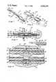
- FIG. 1is a perspective view of the cannula of the present invention, in this case an endotracheal tube, having a radiopaque tip;
- FIG. 2is an exploded view of the distal end of the present cannula, including a parent member and a radiopaque tip, and a back up plug used in dielectrically joining these elements;
- FIG. 3is a side cross sectional view of the present cannula and the dielectric heating apparatus utilized in fusing the parent member and radiopaque tip together;
- FIG. 4is a close up view of the junction area and the parent member and radiopaque tip before they are fused together;
- FIG. 5is a close up view of the joint after fusion of the parent member and tip.
- the composite cannula 10 of the present inventionincluding a parent member 12, in this case an endotracheal tube, and an integral radiopaque tip 14.
- a parent member 12in this case an endotracheal tube
- an integral radiopaque tip 14can also be applied to a wide variety of cannulas, such as tracheostomy tubes, catheters, and the like.
- the cannula 10 of the present inventionmay take the form of a tracheostomy tube having a disposable inner cannula, such as that described and claimed in U.S. Pat. No. 4,419,095, issued Dec. 6, 1983 and assigned to Shiley, Inc., assignee of the present invention.
- an inflatable cuff 16Attached to the parent member 12 of the present cannula 10, at a location just behind the radiopaque tip 14, is an inflatable cuff 16. When inflated, this cuff 16 provides an air tight seal between the endotracheal tube 10 and the inner walls of the trachea. Each end of the cuff 16 is attached to the parent member 12 so as to form front and rear sleeves 18 and 20, respectively.
- the cuff 16is inflated by means of a flexible inflation tube 22 which extends through a small lumen in the wall of the endotracheal tube 10 and into the cuff 16.
- Shown attached to the proximal end 26 of the parent member 12is an endotracheal tube connector 28 which is described and claimed in U.S. Pat. No. 4,146,034, assigned to Shiley, Inc. This connector 28 is used to connect the endotracheal tube 10 to respiratory or anesthetic equipment (not shown).
- FIG. 2is an exploded view of the distal end 24 of the present unitary cannula 10, including its constituent elements, the parent member 12 and a radiopaque tip 14. Shown in dotted lines is a back up plug 30 which is utilized in fusing these two elements together, as will be explained in more detail below.
- the radiopaque tip 14is provided with a beveled, distal end 32 and a flat, non-beveled proximal end 34, which mates with the distal end 36 of the parent member 10.
- An oblong-shaped fenestration 38is formed in the side of the tip in order to provide an alternate exit for gas or liquid in the event that the main opening 40 of the cannula 10 should become clogged with mucus or lodged against an internal bodily wall or organ.
- the proximal end 34 of the tip 14is also characterized by an annular section 42 having a reduced diameter.
- the location of this section 42is such that it accommodates the front sleeve 20 of the cuff 16 so that the attachment of the sleeve 20 does not create a raised ridge around the exterior surface 44 of the cannula 10.
- This constructionmaintains the smoothness of the cannula's exterior surface 44 and prevents any irritation or abrasion to internal tissues that could be caused by such a ridge during insertion and placement of the cannula 10 within the patient.
- the configuration of the radiopaque tip 14 of the cannula 10 of the present inventionis such that it can be easily distinguished, in X rays or fluoroscopic images, from internal bodily parts. Furthermore, since the entire tip 14 of the present cannula 10 is radiopaque, rather than a mere line on the side of the tip or a ring encircling the opening 40, the precise orientation of the tip 14 with respect to such internal bodily parts can be easily determined. Therefore, the radiopaque tip 14 of the present invention greatly facilitates insertion and placement of the present cannula 10 and prevents internal injury or discomfort to the patient.
- the parent member 12 and tip 14 of the present cannula 10are separately pre-formed from compatible materials which are capable of being welded or fused together.
- a number of flexible, biologically safe, polymeric or elastomeric materialscan be utilized in the construction of the present cannula, with the specific selection of the material depending primarily upon the application of the cannula and the desired cost of its manufacture.
- suitable materialsinclude, but are not limited to polyvinyl chloride, polyurethane, silicone rubber, latex, polyamides, etc.
- the tip materialis blended with a suitable non-toxic radiopaque substance, preferably bismuth trioxide or a barium compound.
- the tip 14can also be constructed by any one of a number of suitable methods. For example, it may be injection or compression molded or extruded and then dielectrically end formed. Alternatively, casting or slushing processes may be utilized.
- the parent member 12is typically extruded from a clear material (in order to permit visual examination of its contents) although other manufacturing techniques can also be employed.
- the parent member 12 and tip 14 of the present cannula 10can then be constructed to have different hardnesses.
- the tip 14can be made softer than the parent member 12 in order to prevent pain and injury to the patient.
- the parent member 12can remain sufficiently rigid to facilitate insertion of the cannula 10.
- the difference in hardnesses, however, between the parent member 12 and the tip 14is sufficiently small to permit the use of a dielectric process, explained in more detail below, to fuse them together.
- a cannula 10 in which the parent member 12 has a Shore A hardness factor of about 85 to 95, and the tip 14 has a Shore A factor of about 10 less than its respective parent member 12,provides an optimum in both tip softness and parent rigidity. Furthermore, when desirable, the present cannula 10 can be constructed so that the tip 14 is harder than the parent device 12.
- the cannula 10 of the present inventionis provided with completely smooth surfaces.
- the smoothness of the interior and exterior surfaces 46 and 44, respectively, of the parent member 12continues across the joint 48 between the tip 14 and parent member 12 (shown in a dotted line in FIG. 1 beneath the front sleeve 20) to provide a continuous, uniformly dimensioned cannula 10.
- the smooth interior surface 46inhibits the accumulation of mucus within the cannula 10 and the smoothness of the exterior surface 44 prevents irritation and injury to delicate internal tissue.
- FIGS. 3 and 4cross-sectionally illustrate a dielectric heating apparatus 50 for integrally welding the radiopaque tip 14 to the parent member 12.
- this dielectric apparatus 50is shown engaging the distal end 24 of the present cannula 10, including the parent member 12, the tip 14, which is mated with the parent member 12 at the joint 48, and the back up plug 30 (shown in FIG. 2).
- the joint 48 and junction area between the parent member 12 and tip 14are shown in more detail in FIG. 4.
- the back up plug 30is provided with a beveled proximal end 52, as shown in FIG. 2, which corresponds with the beveled distal end 32 of the tip 14, and a flat distal end 53.
- the proximal end 52 of the plug 30is positioned against the tip 14 to maintain its proper orientation relative to the parent member 12 during the fusion process.
- the dielectric heating apparatus 50includes an outer annular die 54, which also serves as an outer electrode 58, and an inner cylindrical die or mandrel 56, which encapsulates a long, rod-like electrode 60.
- the outer die 54is positioned over and closely surrounds the junction area of the cannula 10, including the distal end 36 of the parent member 12, the tip 14, and a portion of the back up plug 30.
- the interior surface 62 of this outer die 54is slightly convex, as shown more clearly in FIG. 4, so that its smallest inner diameter is adjacent the joint 48 while its largest inner diameter is located at its opposite ends.
- a set screw 64connects this outer die 54 to a collar 66 which in turn is connected to a terminal of the generator of the dielectric apparatus 50.
- the outer die 54is constructed from a conductive metal, such as brass or beryllium copper, to permit it to serve simultaneously as an electrode 58.
- the inner die or mandrel 56is shown inserted through the back up plug 30, the radiopaque tip 14, and into the distal end 36 of the parent member 12.
- the encapsulated inner electrode 60is positioned generally opposite the outer electrode 58 and extends almost the entire length of the mandrel 56.
- This inner electrode 60makes contact with a metal plate 68 which in turn is connected to a terminal of the generator of the dielectric heating apparatus 50.
- the inner electrode 60is connected to the negative terminal of the generator and the outer electrode is connected to the positive terminal of the generator, although this configuration can be reversed.
- Contact between the inner electrode 60 and the metal plate 68can be made by any suitable means, such as the threaded engagement 70 shown in FIG. 3.
- the inner electrode 60is also provided with an annular collar 72 which is located directly adjacent the joint 48.
- the mandrel 56is comprised of two parts: a hollow outer shell 74, which houses the electrode 60, and an inner tubular member 76, which fits tightly over the electrode 60 and within the shell 74.
- the e1ectrode 60is first inserted into the shell 74 and then held securely in place by fitting the tubular member 76 over the electrode 60 so that it also fits within the shell 74.
- These partsfit tightly around the electrode 60 in order to prevent the presence of air within the mandrel 56. Therefore, in order to facilitate the assembly of the mandrel 56, the shell 74 is provided with a vent channel 78 in its distal end (shown in FIG. 3) and the outer surface of the electrode 60 is grooved (not shown), thus permitting the displacement of the air as the electrode 60 and tubular member 76 are inserted into the shell 74.
- the mandrel 56is constructed from a material having a high dielectric constant, preferably Teflon (a trademark of the Dupont Company), although other insulative materials such as lexan or polypropylene styrene are also suitable. These insulative materials are advantageously unaffected by the high frequency current generated by the dielectric heating apparatus.
- the back up plug 30is preferably constructed from a poor conductor of radio frequency electric current, such as one of the materials just mentioned.
- FIG. 3illustrates in cross-section a spring 80, one end of which bears against the metal plate 68 of the dielectric heating apparatus 50 while its other end bears against the flat distal end 53 of the back up plug 30.
- This spring 80applies, through the back up plug 30, a force of 20-35 pounds per square inch to the radiopaque tip 14 in order to hold the tip 14 securely in place during its fusion to the parent member 12.
- the spring 80also serves to pressurize the joint 48 to eliminate the air within it and to facilitate the elimination of dimensional differences between the mating surfaces 34 and 36 of the tip 14 and parent member 12, as will be described in more detail below.
- Other equivalent pressurizing meanssuch as an air cy1inder, can also be utilized.
- This spring 80is preferably constructed from a non-inductive metal, such as beryllium copper, so as to be unaffected by the current generated by the dielectric heating apparatus 50.
- the outer die 54 and mandrel 56 of the dielectric apparatus 50conform very closely to the diametrical dimensions of the parent member 12. That is, the inner diameter of the outer die 54 closely approximates the outer diameter of the parent member 12, and the outer diameter of the mandrel 56 is substantially the same as its inner diameter.
- these elementsare molded and formed by these dies 54 and 56 so as to be dimensionally uniform with the parent member 12.
- the heated surfaces 44 and 46 of the cannula 10tend to swell at the joint 48 and, if not constrained by the dies 54 and 56, would form a raised ridge or mound at this point.
- the configuration of the dies 54 and 56 of the dielectric heating apparatus 56produces a cannula 10 having smooth, uniformly dimensioned surfaces 44 and 46.
- the smallest inner diameter of the outer electrode 58is located at the joint 48 and the largest outer diameter of the inner electrode 60, which is provided by the collar 72, is directly adjacent the joint 48.
- This constructionpermits the heat generated by the dielectric apparatus 50 to be concentrated at the joint 48.
- the inner and outer diameters of these mating elementsneed not be identical nor do the mating surfaces 34 and 36 have to be precisely parallel or flush.
- the elongate configuration of the inner and outer electrodes 60 and 58, respectivelyinsures that heat will be generated completely across the junction area, and not at the joint 48 only, further eliminating dimensional irregularities between the tip 14 and parent member 12.
- FIGS. 4 and 5illustrate the manner in which the present dielectric heating apparatus 50 eliminates differences in the inner and outer diameters of the parent member 12 and radiopaque tip 14.
- FIG. 4illustrates the joint 48 prior to the fusion of these two elements together.
- the area of reduced diameter 42 on the tip 14forms an annular ridge 49 at the joint 48 because it causes the outer diameter of the mating surface 34 of the tip 14 to be less than the outer diameter of the mating surface 36 on the parent member 12.
- this area of reduced diameter 42expands or swells at the joint 48 (due to the concentration of heat at this location) so that the outer diameters of the mating surfaces 34 and 36 are equal.
- the ridge 49 at the joint 48is eliminated to provide a smooth exterior surface 44 on the cannula 10. Furthermore, a portion of the area of reduced diameter 42 advantageously remains after fusion, as indicated at 43 in FIG. 5, since it is not within the area of heat concentration created between the outer electrode 58 and the inner collar 72. Therefore, this reduced area 43 receives the front sleeve 20 of the cuff 16 so that the smoothness of the exterior surface 44 of the cannula 10 is maintained.
- the dielectric heating apparatus 50produces a cannula 10 having completely smooth interior and exterior surfaces, 46 and 44, respectively. There are no projecting edges or ridges at the joint 48, or anywhere else, that could act as focal points for the accumulation of mucus or other bodily secretions. Furthermore, since the mating surfaces of the tip 14 and parent member 12 need not be exactly flush or true, the manufacture and assembly of these elements are greatly facilitated.
- FIG. 4illustrates the features of the dielectric heating apparatus 50 which prevents the burning or scorching of the tip 14 and parent member 12 as they are welded together to form the present cannula 10. Since air and water are better conductors of the electric current generated by the dielectric apparatus 50 than the cannula material, it is important that these elements be eliminated from the joint 48 and junction area. Thus, prior to the fusion of the tip 14 to the parent member 12, both parts are thoroughly dried.
- the hot expanding air existing in the junction areais vented from the interstices between the dies 54 and 56 and the cannula 10 in order to prevent burning.
- Such ventingis accomplished outside of the cannula 10 by the tapered, convex interior surface 62 of the outer die 54 which permits air to escape the junction area by means of its gradually increasing inner diameter.
- airis vented by means of longitudinal grooves 82, shown in FIG. 4, formed in the exterior surface of the mandrel 56.
- the mandrel 56is assembled so as to substantially eliminate any air existing within, and it is air tight in order to prevent the entrance of air.
- any air existing in the joint 48will be forced out by the pressure exerted by the spring 80. Once eliminated from the joint 48, this air will be vented from the junction area along the channels described above.
- Burningis also prevented, in spite of the close proximity between the electrodes 58 and 60 of the cannula 10, by encapsulating one electrode in a highly insulative material.
- the inner electrode 60is encapsulated in such an insulative material so as to form the mandrel 56 shown in FIGS. 3 and 4.
- This constructionadvantageously permits the cannula 10 of the present invention to conform to the shape of the mandrel 56, thereby providing a smooth interior surface 46, while at the same time insulating that surface to prevent it from burning.
- edges 84 of the collar 72 on the inner electrode 60are rounded. Sharp corners and edges provide jumping off points for the radio frequency electric current to arch across to the outer elcctrode 58. By rounding the edges 84 of the collar 72, such arcing is prevented and the burning of the surfaces of the cannula 10 is further inhibited.
- the dielectric heating apparatus 50In operation, the dielectric heating apparatus 50 generates a high frequency electric current which passes between the electrodes 58 and 60 and through the mated ends of the tip 14 and parent member 12.
- the heat generated by the dielectric apparatus 50is concentrated at the joint 48, but also exists across the junction area due to the extended configuration of the electrodes 58 and 60. This heat causes the tip 14 and parent member 12 to partially liquify or melt, and as they cool and harden, they are welded to one another. During this fusion process, however, the joint 48 becomes homogenous, both structurally and dimensionally, as explained above.
- the radiopaque tip 14is integrally attached to a non-radiopaque parent member 12 to form a unitary cannula 10 whose tensile strength at the joint 48 and junction area is substantially the same as the remainder of the cannula 10. This strength permits the cannula 10 to be advantageously thin-walled; that is, having a maximum inner diameter and a minimum outer diameter.
- the radio frequency current produced by the dielectric heating apparatus 50is a conventional pulsating DC current and is passed through the cannula 10 for only a very short time, e.g. about one-half second, although this time will vary depending upon the size and wall thickness of the cannula 10.
- this heating timemust be carefully controlled so that the cannula 10, and particularly the tip 14 which is generally softer than the rest of the cannula 10, does not liquify too much and begin to flow.
- the power necessary to generate this heating currentcan be determined by the following equation:
- Ppower (in watts/in 3 )
- Eis the voltage across the electrodes (in kilovolts)
- fis the frequency (in megaHertz)
- e'is the dielectric constant of the cannula material
- tan ⁇is the dissipation factor of the cannula material
- dis the distance (in inches) between the outer electrode 58 and the collar 72 on the inner electrode 60.
- the required powermay fall within a range of 400-600 watts with the frequency being 40-95 megaHertz, although these figures may vary widely depending on the thickness and material of the cannula wall and the overall diameter of the cannula.
- the dielectric heating apparatus and method for using itprovides the unitary cannula of the present invention with an integral radiopaque tip.
- this apparatus and the cannula itselfhave been illustrated in connection with a cylindrical cannula, cannulas of other configurations and shapes can also be formed in accordance with the principles of the present invention.
- the cannula of the present inventioncan also be constructed by using other suitable heating and joining techniques, such as induction or impulse heating and ultrasonics.
Landscapes
- Engineering & Computer Science (AREA)
- Mechanical Engineering (AREA)
- Health & Medical Sciences (AREA)
- Life Sciences & Earth Sciences (AREA)
- Heart & Thoracic Surgery (AREA)
- Anesthesiology (AREA)
- Biophysics (AREA)
- Pulmonology (AREA)
- Child & Adolescent Psychology (AREA)
- Biomedical Technology (AREA)
- Hematology (AREA)
- Animal Behavior & Ethology (AREA)
- General Health & Medical Sciences (AREA)
- Public Health (AREA)
- Veterinary Medicine (AREA)
- Media Introduction/Drainage Providing Device (AREA)
Abstract
Description
P=1.41[E/d].sup.2 fe' tan δ
Claims (9)
Priority Applications (1)
| Application Number | Priority Date | Filing Date | Title |
|---|---|---|---|
| US06/596,069US4588399A (en) | 1980-05-14 | 1984-04-03 | Cannula with radiopaque tip |
Applications Claiming Priority (2)
| Application Number | Priority Date | Filing Date | Title |
|---|---|---|---|
| US06/149,568US4419095A (en) | 1980-05-14 | 1980-05-14 | Cannula with radiopaque tip |
| US06/596,069US4588399A (en) | 1980-05-14 | 1984-04-03 | Cannula with radiopaque tip |
Related Parent Applications (1)
| Application Number | Title | Priority Date | Filing Date |
|---|---|---|---|
| US06462907Continuation | 1983-02-02 |
Publications (1)
| Publication Number | Publication Date |
|---|---|
| US4588399Atrue US4588399A (en) | 1986-05-13 |
Family
ID=26846850
Family Applications (1)
| Application Number | Title | Priority Date | Filing Date |
|---|---|---|---|
| US06/596,069Expired - LifetimeUS4588399A (en) | 1980-05-14 | 1984-04-03 | Cannula with radiopaque tip |
Country Status (1)
| Country | Link |
|---|---|
| US (1) | US4588399A (en) |
Cited By (72)
| Publication number | Priority date | Publication date | Assignee | Title |
|---|---|---|---|---|
| US4705510A (en)* | 1984-12-18 | 1987-11-10 | The Kendall Company | Nephrostomy catheter with formed tip |
| WO1989005164A1 (en)* | 1987-12-07 | 1989-06-15 | Nimbus Medical, Inc. | Inflow cannula for intravascular blood pumps |
| US5045072A (en)* | 1989-06-13 | 1991-09-03 | Cordis Corporation | Catheter having highly radiopaque, flexible tip |
| US5058580A (en)* | 1988-05-11 | 1991-10-22 | Hazard Patrick B | Percutaneous tracheostomy tube |
| US5499625A (en)* | 1994-01-27 | 1996-03-19 | The Kendall Company | Esophageal-tracheal double lumen airway |
| US5520174A (en)* | 1994-02-14 | 1996-05-28 | Evans; Larry L. | Tracheostomy tube guard |
| US5603705A (en)* | 1993-12-22 | 1997-02-18 | Scimed Life Systems, Inc. | Catheter joint with restraining device |
| US5820612A (en)* | 1994-01-07 | 1998-10-13 | Scimed Life Systems, Inc. | Catheter joint with counterbore |
| US5891110A (en)* | 1997-10-15 | 1999-04-06 | Scimed Life Systems, Inc. | Over-the-wire catheter with improved trackability |
| US5908413A (en)* | 1997-10-03 | 1999-06-01 | Scimed Life Systems, Inc. | Radiopaque catheter and method of manufacture thereof |
| US5951495A (en)* | 1993-12-22 | 1999-09-14 | Scimed Life Systems, Inc. | Catheter having an adhesive braid wire constraint and method of manufacture |
| US5954651A (en)* | 1993-08-18 | 1999-09-21 | Scimed Life Systems, Inc. | Catheter having a high tensile strength braid wire constraint |
| US6036682A (en)* | 1997-12-02 | 2000-03-14 | Scimed Life Systems, Inc. | Catheter having a plurality of integral radiopaque bands |
| US6048338A (en)* | 1997-10-15 | 2000-04-11 | Scimed Life Systems, Inc. | Catheter with spiral cut transition member |
| US6077258A (en)* | 1997-10-03 | 2000-06-20 | Scimed Life Systems, Inc. | Braided angiography catheter having full length radiopacity and controlled flexibility |
| US6113579A (en)* | 1998-03-04 | 2000-09-05 | Scimed Life Systems, Inc. | Catheter tip designs and methods for improved stent crossing |
| US6206852B1 (en) | 1999-12-15 | 2001-03-27 | Advanced Cardiovascular Systems, Inc. | Balloon catheter having a small profile catheter |
| US6210396B1 (en) | 1999-06-24 | 2001-04-03 | Medtronic, Inc. | Guiding catheter with tungsten loaded band |
| US6264630B1 (en) | 1998-12-23 | 2001-07-24 | Scimed Life Systems, Inc. | Balloon catheter having an oscillating tip configuration |
| US6285903B1 (en) | 1998-06-30 | 2001-09-04 | Eclipse Surgical Technologies, Inc. | Intracorporeal device with radiopaque marker |
| US6340368B1 (en) | 1998-10-23 | 2002-01-22 | Medtronic Inc. | Implantable device with radiopaque ends |
| US6361557B1 (en) | 1999-02-05 | 2002-03-26 | Medtronic Ave, Inc. | Staplebutton radiopaque marker |
| US6378523B1 (en) | 2000-03-15 | 2002-04-30 | Evergreen Medical Incorporated | Endotracheal tube having a beveled tip and orientation indicator |
| US20020111649A1 (en)* | 2001-02-14 | 2002-08-15 | Microvena Corporation | Rolled tip recovery catheter |
| US6464684B1 (en) | 1998-09-09 | 2002-10-15 | Scimed Life Systems, Inc. | Catheter having regions of differing braid densities and methods of manufacture therefor |
| US6517515B1 (en) | 1998-03-04 | 2003-02-11 | Scimed Life Systems, Inc. | Catheter having variable size guide wire lumen |
| US20030060842A1 (en)* | 2001-09-27 | 2003-03-27 | Yem Chin | Method and apparatus for measuring and controlling blade depth of a tissue cutting apparatus in an endoscopic catheter |
| US6540721B1 (en) | 1999-12-29 | 2003-04-01 | Advanced Cardiovascular Systems, Inc. | Balloon catheter with flexible radiopaque polymeric marker |
| US20030078613A1 (en)* | 2001-10-24 | 2003-04-24 | Scimed Life Systems, Inc. | Distal balloon waist material relief and method of manufacture |
| US6623504B2 (en) | 2000-12-08 | 2003-09-23 | Scimed Life Systems, Inc. | Balloon catheter with radiopaque distal tip |
| US6733489B2 (en)* | 2002-09-26 | 2004-05-11 | Angiodynamics, Inc. | Vascular orientation marker for determining the orientation of a blood vessel |
| US20050010194A1 (en)* | 2003-07-09 | 2005-01-13 | Scimed Life Systems, Inc. | Method of forming catheter distal tip |
| US20050043713A1 (en)* | 2003-08-20 | 2005-02-24 | Scimed Life Systems, Inc. | Catheter with thin-walled braid |
| US20050043714A1 (en)* | 2003-08-20 | 2005-02-24 | Scimed Life Systems, Inc. | Medical device incorporating a polymer blend |
| US20050064223A1 (en)* | 2003-09-22 | 2005-03-24 | Bavaro Vincent Peter | Polymeric marker with high radiopacity |
| US20050065434A1 (en)* | 2003-09-22 | 2005-03-24 | Bavaro Vincent P. | Polymeric marker with high radiopacity for use in medical devices |
| US20050137519A1 (en)* | 2003-12-17 | 2005-06-23 | Scimed Life Systems, Inc. | Composite catheter braid |
| US20050149176A1 (en)* | 2003-12-29 | 2005-07-07 | Scimed Life Systems, Inc. | Selectively light curable support members for medical devices |
| US6945970B2 (en) | 2001-12-27 | 2005-09-20 | Scimed Life Systems, Inc. | Catheter incorporating a curable polymer layer to control flexibility and method of manufacture |
| US20050283226A1 (en)* | 2004-06-18 | 2005-12-22 | Scimed Life Systems, Inc. | Medical devices |
| US20060030875A1 (en)* | 2004-08-04 | 2006-02-09 | Tessmer Alexander W | Non-entangling vena cava filter |
| US20060111649A1 (en)* | 2004-11-19 | 2006-05-25 | Scimed Life Systems, Inc. | Catheter having improved torque response and curve retention |
| US20060127561A1 (en)* | 2001-12-18 | 2006-06-15 | Stephen Griffin | Guide wire with adjustable flexibility |
| US20060135979A1 (en)* | 2004-12-16 | 2006-06-22 | Scimed Life Systems, Inc. | Catheter tip to reduce wire lock |
| US20060178695A1 (en)* | 2005-02-04 | 2006-08-10 | Decant Leonard J Jr | Vascular filter with sensing capability |
| US20070021811A1 (en)* | 2005-07-19 | 2007-01-25 | Cardiac Pacemakers, Inc. | Medical device including radiopaque polymer coated coil and method therefor |
| US20080009831A1 (en)* | 2004-12-03 | 2008-01-10 | Scimed Life Systems, Inc. | Selectively flexible catheter and method of use |
| US20080125752A1 (en)* | 2006-08-09 | 2008-05-29 | Boston Scientific Scimed, Inc. | Catheter assembly having a modified reinforcement layer |
| US20080183192A1 (en)* | 2007-01-26 | 2008-07-31 | Laurimed Llc | Contralateral insertion method to treat herniation with device using visualization components |
| US20080188826A1 (en)* | 2007-02-01 | 2008-08-07 | Laurimed, Llc | Methods and devices for treating tissue |
| US20080230070A1 (en)* | 2007-03-20 | 2008-09-25 | Felix Gregorian | Endotracheal Tube with Radiopaque Distal End Marker |
| US20080306453A1 (en)* | 2007-06-06 | 2008-12-11 | Cook Incorporated | Coupling wire guide and method for making same |
| US20090259126A1 (en)* | 2008-04-02 | 2009-10-15 | Laurimed, Llc | Methods and devices for delivering injections |
| US20090299404A1 (en)* | 2006-05-02 | 2009-12-03 | C.R. Bard, Inc. | Vena cava filter formed from a sheet |
| WO2009146790A1 (en)* | 2008-05-29 | 2009-12-10 | Pajunk Gmbh & Co. Kg Besitzverwaltung | Cannula, in particular for local anaesthesia |
| US20100030254A1 (en)* | 2006-06-05 | 2010-02-04 | C. R. Bard, Inc. | Embolus Blood Clot Filter Utilizable With A Single Delivery System Or A Single Retrieval System In One of A Femoral or Jugular Access |
| US20100030253A1 (en)* | 2005-11-18 | 2010-02-04 | C.R. Brard, Inc. | Vena cava filter with filament |
| US7794473B2 (en) | 2004-11-12 | 2010-09-14 | C.R. Bard, Inc. | Filter delivery system |
| US20100256669A1 (en)* | 2005-12-02 | 2010-10-07 | C.R. Bard, Inc. | Helical Vena Cava Filter |
| US20110230947A1 (en)* | 2008-08-26 | 2011-09-22 | Cook ,Edical Tecnhologies Llc | Thoracic introducer |
| US8292909B1 (en) | 2010-06-30 | 2012-10-23 | Laurimed, Llc | Devices and methods for cutting tissue |
| US8430903B2 (en) | 2005-08-09 | 2013-04-30 | C. R. Bard, Inc. | Embolus blood clot filter and delivery system |
| US8574261B2 (en) | 2005-05-12 | 2013-11-05 | C. R. Bard, Inc. | Removable embolus blood clot filter |
| US8613754B2 (en) | 2005-05-12 | 2013-12-24 | C. R. Bard, Inc. | Tubular filter |
| US8657842B2 (en) | 2010-06-30 | 2014-02-25 | Laurimed, Llc | Devices and methods for cutting tissue |
| US8690906B2 (en) | 1998-09-25 | 2014-04-08 | C.R. Bard, Inc. | Removeable embolus blood clot filter and filter delivery unit |
| US8815099B1 (en) | 2014-01-21 | 2014-08-26 | Laurimed, Llc | Devices and methods for filtering and/or collecting tissue |
| US9204956B2 (en) | 2002-02-20 | 2015-12-08 | C. R. Bard, Inc. | IVC filter with translating hooks |
| US9763731B2 (en) | 2012-02-10 | 2017-09-19 | Myromed, Llc | Vacuum powered rotary devices and methods |
| EP4000676A1 (en)* | 2020-11-11 | 2022-05-25 | Fiab S.P.A. | Tubular element for medical use |
| GB2625246A (en)* | 2022-11-22 | 2024-06-19 | Arthur Wills Anthony | Manufacture of extended geometries in multicomponent devices |
| US12115057B2 (en) | 2005-05-12 | 2024-10-15 | C.R. Bard, Inc. | Tubular filter |
Citations (25)
| Publication number | Priority date | Publication date | Assignee | Title |
|---|---|---|---|---|
| US2330399A (en)* | 1937-09-11 | 1943-09-28 | American Anode Inc | Distensible bag catheter |
| US2857915A (en)* | 1956-04-02 | 1958-10-28 | David S Sheridan | X-ray catheter |
| US2930377A (en)* | 1958-06-02 | 1960-03-29 | Baxter Don Inc | Surgical tube |
| US3086525A (en)* | 1961-04-21 | 1963-04-23 | John G Whitcomb | Device for intra-cavitary infusion of local anesthetic agent or other medicinal solutions |
| US3190290A (en)* | 1962-02-08 | 1965-06-22 | Brunswick Corp | Intercostal catheters |
| US3232810A (en)* | 1960-07-06 | 1966-02-01 | Eastman Kodak Co | Method for dielectric sealing of polyester materials |
| US3281302A (en)* | 1963-09-09 | 1966-10-25 | Dow Chemical Co | Method and apparatus for welding thermoplastic films |
| US3360417A (en)* | 1964-04-01 | 1967-12-26 | Peterson Electronic Die Co Inc | Heat sealing machine for bonding flexible strips to thermoplastic surfaces |
| US3407817A (en)* | 1965-07-26 | 1968-10-29 | Air Reduction Inc | Catheter with cuff inflater and indicator |
| US3605750A (en)* | 1969-04-07 | 1971-09-20 | David S Sheridan | X-ray tip catheter |
| US3709227A (en)* | 1970-04-28 | 1973-01-09 | Scott And White Memorial Hospi | Endotracheal tube with positive check valve air seal |
| US3734100A (en)* | 1973-05-07 | 1973-05-22 | Medical Products Corp | Catheter tubes |
| GB1318277A (en)* | 1969-09-23 | 1973-05-23 | Sheridan D S | Balloon type catheters |
| US3749134A (en)* | 1972-02-02 | 1973-07-31 | Sunlite Plastics Inc | Radiographically opaque plastic tubing |
| US3788328A (en)* | 1971-04-29 | 1974-01-29 | Sherwood Medical Ind Inc | Cardiovascular catheter |
| US3812860A (en)* | 1973-04-05 | 1974-05-28 | Int Paper Co | Retention catheter |
| US3890976A (en)* | 1972-10-26 | 1975-06-24 | Medical Products Corp | Catheter tip assembly |
| US3923580A (en)* | 1971-04-08 | 1975-12-02 | Heller William C Jun | Fabricating method and article formed thereby |
| US3941641A (en)* | 1974-02-26 | 1976-03-02 | William C. Heller, Jr. | Bonding method and apparatus |
| US3959058A (en)* | 1974-11-08 | 1976-05-25 | Plastronics, Inc. | Method and apparatus for butt-welding tubular plastic members to each other |
| US3972548A (en)* | 1973-11-27 | 1976-08-03 | Aktiebolaget Atomenergi | Method of joining components made of cross-linked polymers |
| US3989571A (en)* | 1973-04-23 | 1976-11-02 | American Hospital Supply Corporation | Method of making a smooth tipped endotracheal tube |
| US4027659A (en)* | 1975-11-21 | 1977-06-07 | Krandex Corporation | Radiographic opaque and conductive stripped medical tubes |
| US4276874A (en)* | 1978-11-15 | 1981-07-07 | Datascope Corp. | Elongatable balloon catheter |
| US4305392A (en)* | 1978-09-29 | 1981-12-15 | Chester Martin H | Endotracheal tube with suction device |
- 1984
- 1984-04-03USUS06/596,069patent/US4588399A/ennot_activeExpired - Lifetime
Patent Citations (25)
| Publication number | Priority date | Publication date | Assignee | Title |
|---|---|---|---|---|
| US2330399A (en)* | 1937-09-11 | 1943-09-28 | American Anode Inc | Distensible bag catheter |
| US2857915A (en)* | 1956-04-02 | 1958-10-28 | David S Sheridan | X-ray catheter |
| US2930377A (en)* | 1958-06-02 | 1960-03-29 | Baxter Don Inc | Surgical tube |
| US3232810A (en)* | 1960-07-06 | 1966-02-01 | Eastman Kodak Co | Method for dielectric sealing of polyester materials |
| US3086525A (en)* | 1961-04-21 | 1963-04-23 | John G Whitcomb | Device for intra-cavitary infusion of local anesthetic agent or other medicinal solutions |
| US3190290A (en)* | 1962-02-08 | 1965-06-22 | Brunswick Corp | Intercostal catheters |
| US3281302A (en)* | 1963-09-09 | 1966-10-25 | Dow Chemical Co | Method and apparatus for welding thermoplastic films |
| US3360417A (en)* | 1964-04-01 | 1967-12-26 | Peterson Electronic Die Co Inc | Heat sealing machine for bonding flexible strips to thermoplastic surfaces |
| US3407817A (en)* | 1965-07-26 | 1968-10-29 | Air Reduction Inc | Catheter with cuff inflater and indicator |
| US3605750A (en)* | 1969-04-07 | 1971-09-20 | David S Sheridan | X-ray tip catheter |
| GB1318277A (en)* | 1969-09-23 | 1973-05-23 | Sheridan D S | Balloon type catheters |
| US3709227A (en)* | 1970-04-28 | 1973-01-09 | Scott And White Memorial Hospi | Endotracheal tube with positive check valve air seal |
| US3923580A (en)* | 1971-04-08 | 1975-12-02 | Heller William C Jun | Fabricating method and article formed thereby |
| US3788328A (en)* | 1971-04-29 | 1974-01-29 | Sherwood Medical Ind Inc | Cardiovascular catheter |
| US3749134A (en)* | 1972-02-02 | 1973-07-31 | Sunlite Plastics Inc | Radiographically opaque plastic tubing |
| US3890976A (en)* | 1972-10-26 | 1975-06-24 | Medical Products Corp | Catheter tip assembly |
| US3812860A (en)* | 1973-04-05 | 1974-05-28 | Int Paper Co | Retention catheter |
| US3989571A (en)* | 1973-04-23 | 1976-11-02 | American Hospital Supply Corporation | Method of making a smooth tipped endotracheal tube |
| US3734100A (en)* | 1973-05-07 | 1973-05-22 | Medical Products Corp | Catheter tubes |
| US3972548A (en)* | 1973-11-27 | 1976-08-03 | Aktiebolaget Atomenergi | Method of joining components made of cross-linked polymers |
| US3941641A (en)* | 1974-02-26 | 1976-03-02 | William C. Heller, Jr. | Bonding method and apparatus |
| US3959058A (en)* | 1974-11-08 | 1976-05-25 | Plastronics, Inc. | Method and apparatus for butt-welding tubular plastic members to each other |
| US4027659A (en)* | 1975-11-21 | 1977-06-07 | Krandex Corporation | Radiographic opaque and conductive stripped medical tubes |
| US4305392A (en)* | 1978-09-29 | 1981-12-15 | Chester Martin H | Endotracheal tube with suction device |
| US4276874A (en)* | 1978-11-15 | 1981-07-07 | Datascope Corp. | Elongatable balloon catheter |
Cited By (149)
| Publication number | Priority date | Publication date | Assignee | Title |
|---|---|---|---|---|
| US4705510A (en)* | 1984-12-18 | 1987-11-10 | The Kendall Company | Nephrostomy catheter with formed tip |
| WO1989005164A1 (en)* | 1987-12-07 | 1989-06-15 | Nimbus Medical, Inc. | Inflow cannula for intravascular blood pumps |
| US5058580A (en)* | 1988-05-11 | 1991-10-22 | Hazard Patrick B | Percutaneous tracheostomy tube |
| US5045072A (en)* | 1989-06-13 | 1991-09-03 | Cordis Corporation | Catheter having highly radiopaque, flexible tip |
| US5171232A (en)* | 1989-06-13 | 1992-12-15 | Cordis Corporation | Catheter having highly radiopaque, flexible tip |
| US5954651A (en)* | 1993-08-18 | 1999-09-21 | Scimed Life Systems, Inc. | Catheter having a high tensile strength braid wire constraint |
| US20030083623A1 (en)* | 1993-08-18 | 2003-05-01 | Scimed Life Systems, Inc | Catheter having a high tensile strength braid wire constraint and method of manufacture |
| US6212422B1 (en) | 1993-08-18 | 2001-04-03 | Scimed Life Systems, Inc. | Catheter having a high tensile strength braid wire constraint and method of manufacture |
| US6505066B2 (en) | 1993-08-18 | 2003-01-07 | Scimed Life Systems, Inc. | Catheter having a high tensile strength braid wire constraint and method of manufacture |
| US7297302B2 (en) | 1993-08-18 | 2007-11-20 | Boston Scientific Scimed, Inc. | Catheter having a high tensile strength braid wire constraint and method of manufacture |
| US5603705A (en)* | 1993-12-22 | 1997-02-18 | Scimed Life Systems, Inc. | Catheter joint with restraining device |
| US5951495A (en)* | 1993-12-22 | 1999-09-14 | Scimed Life Systems, Inc. | Catheter having an adhesive braid wire constraint and method of manufacture |
| US5820612A (en)* | 1994-01-07 | 1998-10-13 | Scimed Life Systems, Inc. | Catheter joint with counterbore |
| US5499625A (en)* | 1994-01-27 | 1996-03-19 | The Kendall Company | Esophageal-tracheal double lumen airway |
| US5520174A (en)* | 1994-02-14 | 1996-05-28 | Evans; Larry L. | Tracheostomy tube guard |
| US5908413A (en)* | 1997-10-03 | 1999-06-01 | Scimed Life Systems, Inc. | Radiopaque catheter and method of manufacture thereof |
| US6077258A (en)* | 1997-10-03 | 2000-06-20 | Scimed Life Systems, Inc. | Braided angiography catheter having full length radiopacity and controlled flexibility |
| US6475209B1 (en) | 1997-10-15 | 2002-11-05 | Scimed Life Systems, Inc. | Catheter with spiral cut transition member |
| US8206372B2 (en) | 1997-10-15 | 2012-06-26 | Boston Scientific Scimed, Inc. | Catheter with spiral cut transition member |
| US20100241154A1 (en)* | 1997-10-15 | 2010-09-23 | Boston Scientific Scimed, Inc. | Catheter with Spiral Cut Transition Member |
| US5891110A (en)* | 1997-10-15 | 1999-04-06 | Scimed Life Systems, Inc. | Over-the-wire catheter with improved trackability |
| US7744586B2 (en) | 1997-10-15 | 2010-06-29 | Boston Scientific Scimed, Inc. | Catheter with spiral cut transition member |
| US20070005009A1 (en)* | 1997-10-15 | 2007-01-04 | Scimed Life Systems, Inc. | Catheter with spiral cut transition member |
| US7115183B2 (en) | 1997-10-15 | 2006-10-03 | Scimed Life Systems, Inc. | Catheter with spiral cut transition member |
| US6048338A (en)* | 1997-10-15 | 2000-04-11 | Scimed Life Systems, Inc. | Catheter with spiral cut transition member |
| US6036682A (en)* | 1997-12-02 | 2000-03-14 | Scimed Life Systems, Inc. | Catheter having a plurality of integral radiopaque bands |
| US6517515B1 (en) | 1998-03-04 | 2003-02-11 | Scimed Life Systems, Inc. | Catheter having variable size guide wire lumen |
| US6113579A (en)* | 1998-03-04 | 2000-09-05 | Scimed Life Systems, Inc. | Catheter tip designs and methods for improved stent crossing |
| US6285903B1 (en) | 1998-06-30 | 2001-09-04 | Eclipse Surgical Technologies, Inc. | Intracorporeal device with radiopaque marker |
| US6464684B1 (en) | 1998-09-09 | 2002-10-15 | Scimed Life Systems, Inc. | Catheter having regions of differing braid densities and methods of manufacture therefor |
| US9351821B2 (en) | 1998-09-25 | 2016-05-31 | C. R. Bard, Inc. | Removable embolus blood clot filter and filter delivery unit |
| US8690906B2 (en) | 1998-09-25 | 2014-04-08 | C.R. Bard, Inc. | Removeable embolus blood clot filter and filter delivery unit |
| US6340368B1 (en) | 1998-10-23 | 2002-01-22 | Medtronic Inc. | Implantable device with radiopaque ends |
| US6264630B1 (en) | 1998-12-23 | 2001-07-24 | Scimed Life Systems, Inc. | Balloon catheter having an oscillating tip configuration |
| US6361557B1 (en) | 1999-02-05 | 2002-03-26 | Medtronic Ave, Inc. | Staplebutton radiopaque marker |
| US6210396B1 (en) | 1999-06-24 | 2001-04-03 | Medtronic, Inc. | Guiding catheter with tungsten loaded band |
| US6206852B1 (en) | 1999-12-15 | 2001-03-27 | Advanced Cardiovascular Systems, Inc. | Balloon catheter having a small profile catheter |
| US6540721B1 (en) | 1999-12-29 | 2003-04-01 | Advanced Cardiovascular Systems, Inc. | Balloon catheter with flexible radiopaque polymeric marker |
| US6378523B1 (en) | 2000-03-15 | 2002-04-30 | Evergreen Medical Incorporated | Endotracheal tube having a beveled tip and orientation indicator |
| US6568393B2 (en) | 2000-03-15 | 2003-05-27 | Evergreen Medical Incorporated | Endotracheal tube having a beveled tip and orientation indicator |
| US6623504B2 (en) | 2000-12-08 | 2003-09-23 | Scimed Life Systems, Inc. | Balloon catheter with radiopaque distal tip |
| US6979343B2 (en) | 2001-02-14 | 2005-12-27 | Ev3 Inc. | Rolled tip recovery catheter |
| US20060052817A1 (en)* | 2001-02-14 | 2006-03-09 | Ev3 Inc. | Rolled tip recovery catheter |
| US8747431B2 (en) | 2001-02-14 | 2014-06-10 | Covidien Lp | Rolled tip recovery catheter |
| US20020111649A1 (en)* | 2001-02-14 | 2002-08-15 | Microvena Corporation | Rolled tip recovery catheter |
| US7819890B2 (en) | 2001-02-14 | 2010-10-26 | Ev3 Inc. | Rolled tip recovery catheter |
| US20110004239A1 (en)* | 2001-02-14 | 2011-01-06 | Ev3 Inc. | Rolled tip recovery catheter |
| US9901709B2 (en) | 2001-02-14 | 2018-02-27 | Covidien Lp | Rolled tip recovery catheter |
| US20090005637A1 (en)* | 2001-09-27 | 2009-01-01 | Scimed Life Systems, Inc. | Method and Apparatus for Measuring and Controlling Blade Depth of a Tissue Cutting Apparatus in an Endoscopic Catheter |
| US20030060842A1 (en)* | 2001-09-27 | 2003-03-27 | Yem Chin | Method and apparatus for measuring and controlling blade depth of a tissue cutting apparatus in an endoscopic catheter |
| US7201763B2 (en) | 2001-10-24 | 2007-04-10 | Boston Scientific Scimed, Inc. | Distal balloon waist material relief and method of manufacture |
| US20030078613A1 (en)* | 2001-10-24 | 2003-04-24 | Scimed Life Systems, Inc. | Distal balloon waist material relief and method of manufacture |
| US20060127561A1 (en)* | 2001-12-18 | 2006-06-15 | Stephen Griffin | Guide wire with adjustable flexibility |
| US7918806B2 (en) | 2001-12-18 | 2011-04-05 | Boston Scientific Scimed, Inc. | Guide wire with adjustable flexibility |
| US6945970B2 (en) | 2001-12-27 | 2005-09-20 | Scimed Life Systems, Inc. | Catheter incorporating a curable polymer layer to control flexibility and method of manufacture |
| US20050283135A1 (en)* | 2001-12-27 | 2005-12-22 | Scimed Life Systems, Inc. | Catheter incorporating a curable polymer layer to control flexibility and method of manufacture |
| US7354430B2 (en) | 2001-12-27 | 2008-04-08 | Boston Scientific Scimed, Inc. | Catheter incorporating a curable polymer layer to control flexibility |
| US9204956B2 (en) | 2002-02-20 | 2015-12-08 | C. R. Bard, Inc. | IVC filter with translating hooks |
| US6733489B2 (en)* | 2002-09-26 | 2004-05-11 | Angiodynamics, Inc. | Vascular orientation marker for determining the orientation of a blood vessel |
| US7597830B2 (en) | 2003-07-09 | 2009-10-06 | Boston Scientific Scimed, Inc. | Method of forming catheter distal tip |
| US20050010194A1 (en)* | 2003-07-09 | 2005-01-13 | Scimed Life Systems, Inc. | Method of forming catheter distal tip |
| US7615043B2 (en) | 2003-08-20 | 2009-11-10 | Boston Scientific Scimed, Inc. | Medical device incorporating a polymer blend |
| US20050043713A1 (en)* | 2003-08-20 | 2005-02-24 | Scimed Life Systems, Inc. | Catheter with thin-walled braid |
| US8251976B2 (en) | 2003-08-20 | 2012-08-28 | Boston Scientific Scimed, Inc. | Medical device incorporating a polymer blend |
| US20050043714A1 (en)* | 2003-08-20 | 2005-02-24 | Scimed Life Systems, Inc. | Medical device incorporating a polymer blend |
| US7824392B2 (en) | 2003-08-20 | 2010-11-02 | Boston Scientific Scimed, Inc. | Catheter with thin-walled braid |
| US8637132B2 (en) | 2003-09-22 | 2014-01-28 | Advanced Cardiovascular Systems, Inc. | Polymeric marker with high radiopacity for use in medical devices |
| US20050064223A1 (en)* | 2003-09-22 | 2005-03-24 | Bavaro Vincent Peter | Polymeric marker with high radiopacity |
| US20110070355A1 (en)* | 2003-09-22 | 2011-03-24 | Advanced Cardiovascular Systems, Inc. | Polymeric marker with high radiopacity for use in medical devices |
| US20050065434A1 (en)* | 2003-09-22 | 2005-03-24 | Bavaro Vincent P. | Polymeric marker with high radiopacity for use in medical devices |
| US7303798B2 (en) | 2003-09-22 | 2007-12-04 | Advanced Cardiovascular Systems, Inc. | Polymeric marker with high radiopacity for use in medical devices |
| US20050064224A1 (en)* | 2003-09-22 | 2005-03-24 | Bavaro Vincent Peter | Polymeric marker with high radiopacity |
| US7833597B2 (en) | 2003-09-22 | 2010-11-16 | Advanced Cardiovascular Systems, Inc. | Polymeric marker with high radiopacity for use in medical devices |
| US20080065010A1 (en)* | 2003-09-22 | 2008-03-13 | Advanced Cardiovascular Systems, Inc. | Polymeric marker with high radiopacity for use in medical devices |
| US20050137519A1 (en)* | 2003-12-17 | 2005-06-23 | Scimed Life Systems, Inc. | Composite catheter braid |
| US7955313B2 (en) | 2003-12-17 | 2011-06-07 | Boston Scientific Scimed, Inc. | Composite catheter braid |
| US20080091259A1 (en)* | 2003-12-29 | 2008-04-17 | Boston Scientific Scimed, Inc. | Selectively Light Curable Support Members for Medical Devices |
| US20050149176A1 (en)* | 2003-12-29 | 2005-07-07 | Scimed Life Systems, Inc. | Selectively light curable support members for medical devices |
| US20050283226A1 (en)* | 2004-06-18 | 2005-12-22 | Scimed Life Systems, Inc. | Medical devices |
| US8372109B2 (en) | 2004-08-04 | 2013-02-12 | C. R. Bard, Inc. | Non-entangling vena cava filter |
| US7704267B2 (en) | 2004-08-04 | 2010-04-27 | C. R. Bard, Inc. | Non-entangling vena cava filter |
| US8628556B2 (en) | 2004-08-04 | 2014-01-14 | C. R. Bard, Inc. | Non-entangling vena cava filter |
| US20100174310A1 (en)* | 2004-08-04 | 2010-07-08 | C. R. Bard, Inc. | Non-entangling vena cava filter |
| US9144484B2 (en) | 2004-08-04 | 2015-09-29 | C. R. Bard, Inc. | Non-entangling vena cava filter |
| US20060030875A1 (en)* | 2004-08-04 | 2006-02-09 | Tessmer Alexander W | Non-entangling vena cava filter |
| US11103339B2 (en) | 2004-08-04 | 2021-08-31 | C. R. Bard, Inc. | Non-entangling vena cava filter |
| US8992562B2 (en) | 2004-11-12 | 2015-03-31 | C.R. Bard, Inc. | Filter delivery system |
| US7794473B2 (en) | 2004-11-12 | 2010-09-14 | C.R. Bard, Inc. | Filter delivery system |
| US10512531B2 (en) | 2004-11-12 | 2019-12-24 | C. R. Bard, Inc. | Filter delivery system |
| US20060111649A1 (en)* | 2004-11-19 | 2006-05-25 | Scimed Life Systems, Inc. | Catheter having improved torque response and curve retention |
| US8328791B2 (en) | 2004-12-03 | 2012-12-11 | Stryker Corporation | Selectively flexible catheter and method of use |
| US20080009831A1 (en)* | 2004-12-03 | 2008-01-10 | Scimed Life Systems, Inc. | Selectively flexible catheter and method of use |
| US20110054393A1 (en)* | 2004-12-03 | 2011-03-03 | Boston Scientific Scimed, Inc. | Selectively Flexible Catheter and Method of Use |
| US7828790B2 (en) | 2004-12-03 | 2010-11-09 | Boston Scientific Scimed, Inc. | Selectively flexible catheter and method of use |
| US20060135979A1 (en)* | 2004-12-16 | 2006-06-22 | Scimed Life Systems, Inc. | Catheter tip to reduce wire lock |
| US7744574B2 (en) | 2004-12-16 | 2010-06-29 | Boston Scientific Scimed, Inc. | Catheter tip to reduce wire lock |
| US20060178695A1 (en)* | 2005-02-04 | 2006-08-10 | Decant Leonard J Jr | Vascular filter with sensing capability |
| US8267954B2 (en) | 2005-02-04 | 2012-09-18 | C. R. Bard, Inc. | Vascular filter with sensing capability |
| US8613754B2 (en) | 2005-05-12 | 2013-12-24 | C. R. Bard, Inc. | Tubular filter |
| US12115057B2 (en) | 2005-05-12 | 2024-10-15 | C.R. Bard, Inc. | Tubular filter |
| US11730583B2 (en) | 2005-05-12 | 2023-08-22 | C.R. Band. Inc. | Tubular filter |
| US11554006B2 (en) | 2005-05-12 | 2023-01-17 | C. R. Bard Inc. | Removable embolus blood clot filter |
| US9498318B2 (en) | 2005-05-12 | 2016-11-22 | C.R. Bard, Inc. | Removable embolus blood clot filter |
| US10729527B2 (en) | 2005-05-12 | 2020-08-04 | C.R. Bard, Inc. | Removable embolus blood clot filter |
| US10813738B2 (en) | 2005-05-12 | 2020-10-27 | C.R. Bard, Inc. | Tubular filter |
| US9017367B2 (en) | 2005-05-12 | 2015-04-28 | C. R. Bard, Inc. | Tubular filter |
| US8574261B2 (en) | 2005-05-12 | 2013-11-05 | C. R. Bard, Inc. | Removable embolus blood clot filter |
| US20070021811A1 (en)* | 2005-07-19 | 2007-01-25 | Cardiac Pacemakers, Inc. | Medical device including radiopaque polymer coated coil and method therefor |
| US11517415B2 (en) | 2005-08-09 | 2022-12-06 | C.R. Bard, Inc. | Embolus blood clot filter and delivery system |
| US8430903B2 (en) | 2005-08-09 | 2013-04-30 | C. R. Bard, Inc. | Embolus blood clot filter and delivery system |
| US10492898B2 (en) | 2005-08-09 | 2019-12-03 | C.R. Bard, Inc. | Embolus blood clot filter and delivery system |
| US9387063B2 (en) | 2005-08-09 | 2016-07-12 | C. R. Bard, Inc. | Embolus blood clot filter and delivery system |
| US10842608B2 (en) | 2005-11-18 | 2020-11-24 | C.R. Bard, Inc. | Vena cava filter with filament |
| US12226302B2 (en) | 2005-11-18 | 2025-02-18 | C.R. Bard, Inc. | Vena cava filter with filament |
| US20100030253A1 (en)* | 2005-11-18 | 2010-02-04 | C.R. Brard, Inc. | Vena cava filter with filament |
| US9131999B2 (en) | 2005-11-18 | 2015-09-15 | C.R. Bard Inc. | Vena cava filter with filament |
| US20100256669A1 (en)* | 2005-12-02 | 2010-10-07 | C.R. Bard, Inc. | Helical Vena Cava Filter |
| US10188496B2 (en) | 2006-05-02 | 2019-01-29 | C. R. Bard, Inc. | Vena cava filter formed from a sheet |
| US10980626B2 (en) | 2006-05-02 | 2021-04-20 | C. R. Bard, Inc. | Vena cava filter formed from a sheet |
| US20090299404A1 (en)* | 2006-05-02 | 2009-12-03 | C.R. Bard, Inc. | Vena cava filter formed from a sheet |
| US9326842B2 (en) | 2006-06-05 | 2016-05-03 | C. R . Bard, Inc. | Embolus blood clot filter utilizable with a single delivery system or a single retrieval system in one of a femoral or jugular access |
| US20100030254A1 (en)* | 2006-06-05 | 2010-02-04 | C. R. Bard, Inc. | Embolus Blood Clot Filter Utilizable With A Single Delivery System Or A Single Retrieval System In One of A Femoral or Jugular Access |
| US11141257B2 (en) | 2006-06-05 | 2021-10-12 | C. R. Bard, Inc. | Embolus blood clot filter utilizable with a single delivery system or a single retrieval system in one of a femoral or jugular access |
| US20080125752A1 (en)* | 2006-08-09 | 2008-05-29 | Boston Scientific Scimed, Inc. | Catheter assembly having a modified reinforcement layer |
| US20080183175A1 (en)* | 2007-01-26 | 2008-07-31 | Laurimed Llc | Styli used to position device for carrying out selective discectomy |
| US8414587B2 (en) | 2007-01-26 | 2013-04-09 | Laurimed, Llc | Styli used to position device for carrying out selective discetomy |
| US20080183192A1 (en)* | 2007-01-26 | 2008-07-31 | Laurimed Llc | Contralateral insertion method to treat herniation with device using visualization components |
| US20080188826A1 (en)* | 2007-02-01 | 2008-08-07 | Laurimed, Llc | Methods and devices for treating tissue |
| WO2008116045A3 (en)* | 2007-03-20 | 2008-11-06 | Brigham & Womens Hospital | Endotracheal tube with radiopaque distal end marker |
| US20080230070A1 (en)* | 2007-03-20 | 2008-09-25 | Felix Gregorian | Endotracheal Tube with Radiopaque Distal End Marker |
| US9999737B2 (en) | 2007-03-20 | 2018-06-19 | Felix Gregorian | Endotracheal tube with radiopaque distal end marker |
| US20080306453A1 (en)* | 2007-06-06 | 2008-12-11 | Cook Incorporated | Coupling wire guide and method for making same |
| US8277437B2 (en) | 2008-04-02 | 2012-10-02 | Laurimed, Llc | Method of accessing two lateral recesses |
| US20090259126A1 (en)* | 2008-04-02 | 2009-10-15 | Laurimed, Llc | Methods and devices for delivering injections |
| WO2009146790A1 (en)* | 2008-05-29 | 2009-12-10 | Pajunk Gmbh & Co. Kg Besitzverwaltung | Cannula, in particular for local anaesthesia |
| US8911488B2 (en)* | 2008-08-26 | 2014-12-16 | The Cleveland Clinic Foundation | Thoracic introducer |
| US20110230947A1 (en)* | 2008-08-26 | 2011-09-22 | Cook ,Edical Tecnhologies Llc | Thoracic introducer |
| US8292909B1 (en) | 2010-06-30 | 2012-10-23 | Laurimed, Llc | Devices and methods for cutting tissue |
| US8685052B2 (en) | 2010-06-30 | 2014-04-01 | Laurimed, Llc | Devices and methods for cutting tissue |
| US8840632B2 (en) | 2010-06-30 | 2014-09-23 | Laurimed, Llc | Devices and methods for cutting tissue |
| US9532796B2 (en) | 2010-06-30 | 2017-01-03 | Myromed, Llc | Devices and methods for cutting tissue |
| US8882793B2 (en) | 2010-06-30 | 2014-11-11 | Laurimed, Llc | Devices and methods for cutting tissue |
| US8657842B2 (en) | 2010-06-30 | 2014-02-25 | Laurimed, Llc | Devices and methods for cutting tissue |
| US8298254B2 (en) | 2010-06-30 | 2012-10-30 | Laurimed, Llc | Devices and methods for cutting and evacuating tissue |
| US9763731B2 (en) | 2012-02-10 | 2017-09-19 | Myromed, Llc | Vacuum powered rotary devices and methods |
| US9770289B2 (en) | 2012-02-10 | 2017-09-26 | Myromed, Llc | Vacuum powered rotary devices and methods |
| US8815099B1 (en) | 2014-01-21 | 2014-08-26 | Laurimed, Llc | Devices and methods for filtering and/or collecting tissue |
| EP4000676A1 (en)* | 2020-11-11 | 2022-05-25 | Fiab S.P.A. | Tubular element for medical use |
| GB2625246A (en)* | 2022-11-22 | 2024-06-19 | Arthur Wills Anthony | Manufacture of extended geometries in multicomponent devices |
Similar Documents
| Publication | Publication Date | Title |
|---|---|---|
| US4588399A (en) | Cannula with radiopaque tip | |
| US4419095A (en) | Cannula with radiopaque tip | |
| US4628168A (en) | Dielectric heating device for heating cannula members | |
| US4595012A (en) | Lumen mounted electrodes for pacing and intra-cardiac ECG sensing | |
| EP0805702B1 (en) | Dilation catheter | |
| USRE25788E (en) | Medico-surgical tubes having integral connectors formed in their ends | |
| US6585639B1 (en) | Sheath and method for reconfiguring lung viewing scope | |
| US4248236A (en) | Packaged medical appliance | |
| CA2001057C (en) | Catheter equipped with expansible member and method of manufacturing the same | |
| JPS6211663B2 (en) | ||
| WO1996020751A9 (en) | Dilation catheter | |
| JPH07303702A (en) | Ecarteur,sheath assembly and its manufacture | |
| DE102006047366A1 (en) | Flexible soft catheter for radiofrequency therapy of biological tissue | |
| US4547641A (en) | Method for dielectrically joining tubular members | |
| AU659741B2 (en) | Medico-surgical devices | |
| CA1161123A (en) | Dielectric heating device and method for forming cannula | |
| JPS62176461A (en) | Medical catheter having double wall structure | |
| JP2909993B2 (en) | Manufacturing method of balloon catheter | |
| GB2070935A (en) | Oesophageal probe | |
| JP2014030555A (en) | Medical instrument | |
| JPH01238874A (en) | Inductor capable of separating storage member in vivo from its tip | |
| JPH0636831Y2 (en) | Liquid filling device for enema fluoroscopy | |
| JP3524842B2 (en) | Heater unit for melting and sealing the opening at the tip of the thermoplastic resin tube | |
| CA1261406A (en) | Lumen mounted electrodes for pacing and intra-cardiac ecg sensing | |
| JP2536923B2 (en) | Detachable balloon catheter |
Legal Events
| Date | Code | Title | Description |
|---|---|---|---|
| STCF | Information on status: patent grant | Free format text:PATENTED CASE | |
| FEPP | Fee payment procedure | Free format text:PAYOR NUMBER ASSIGNED (ORIGINAL EVENT CODE: ASPN); ENTITY STATUS OF PATENT OWNER: LARGE ENTITY | |
| FPAY | Fee payment | Year of fee payment:4 | |
| FEPP | Fee payment procedure | Free format text:PAYER NUMBER DE-ASSIGNED (ORIGINAL EVENT CODE: RMPN); ENTITY STATUS OF PATENT OWNER: LARGE ENTITY Free format text:PAYOR NUMBER ASSIGNED (ORIGINAL EVENT CODE: ASPN); ENTITY STATUS OF PATENT OWNER: LARGE ENTITY | |
| AS | Assignment | Owner name:SORIN BIOMEDICAL INC., CALIFORNIA Free format text:ASSIGNMENT OF ASSIGNORS INTEREST.;ASSIGNOR:SHILEY INCORPORATED;REEL/FRAME:006289/0029 Effective date:19920226 | |
| AS | Assignment | Owner name:TRACHEOSTOMY PRODUCTS, INC., CALIFORNIA Free format text:ASSIGNMENT OF ASSIGNORS INTEREST.;ASSIGNOR:SORIN BIOMEDICAL INC.;REEL/FRAME:006348/0886 Effective date:19921216 | |
| FEPP | Fee payment procedure | Free format text:PAYER NUMBER DE-ASSIGNED (ORIGINAL EVENT CODE: RMPN); ENTITY STATUS OF PATENT OWNER: LARGE ENTITY Free format text:PAYOR NUMBER ASSIGNED (ORIGINAL EVENT CODE: ASPN); ENTITY STATUS OF PATENT OWNER: LARGE ENTITY | |
| REMI | Maintenance fee reminder mailed | ||
| REMI | Maintenance fee reminder mailed | ||
| FPAY | Fee payment | Year of fee payment:8 | |
| SULP | Surcharge for late payment | ||
| AS | Assignment | Owner name:MALLINCKRODT MEDICAL, INC., MISSOURI Free format text:ASSIGNMENT OF ASSIGNORS INTEREST;ASSIGNOR:TRACHEOSTOMY PRODUCTS, INC.;REEL/FRAME:007061/0274 Effective date:19940628 | |
| FPAY | Fee payment | Year of fee payment:12 |