US4588268A - Tip-tilt mirror actuation system having simplified driver circuitry - Google Patents
Tip-tilt mirror actuation system having simplified driver circuitryDownload PDFInfo
- Publication number
- US4588268A US4588268AUS06/588,589US58858984AUS4588268AUS 4588268 AUS4588268 AUS 4588268AUS 58858984 AUS58858984 AUS 58858984AUS 4588268 AUS4588268 AUS 4588268A
- Authority
- US
- United States
- Prior art keywords
- actuators
- actuator
- combination
- set forth
- optical element
- Prior art date
- Legal status (The legal status is an assumption and is not a legal conclusion. Google has not performed a legal analysis and makes no representation as to the accuracy of the status listed.)
- Expired - Lifetime
Links
- 230000003287optical effectEffects0.000claimsabstractdescription29
- 230000035945sensitivityEffects0.000claimsabstractdescription16
- 239000000463materialSubstances0.000claimsdescription9
- 230000000694effectsEffects0.000claimsdescription6
- 230000001427coherent effectEffects0.000claimsdescription3
- 230000001747exhibiting effectEffects0.000claims4
- 230000004044responseEffects0.000abstractdescription6
- 238000006073displacement reactionMethods0.000description5
- 230000004043responsivenessEffects0.000description4
- 230000008602contractionEffects0.000description3
- 238000005452bendingMethods0.000description2
- 230000001627detrimental effectEffects0.000description2
- 239000002305electric materialSubstances0.000description2
- 238000012986modificationMethods0.000description2
- 230000004048modificationEffects0.000description2
- 230000010287polarizationEffects0.000description2
- 238000010420art techniqueMethods0.000description1
- 230000009977dual effectEffects0.000description1
- 230000005684electric fieldEffects0.000description1
- 230000001939inductive effectEffects0.000description1
- 239000013642negative controlSubstances0.000description1
- 238000000926separation methodMethods0.000description1
Images

Classifications
- G—PHYSICS
- G02—OPTICS
- G02B—OPTICAL ELEMENTS, SYSTEMS OR APPARATUS
- G02B26/00—Optical devices or arrangements for the control of light using movable or deformable optical elements
- G02B26/06—Optical devices or arrangements for the control of light using movable or deformable optical elements for controlling the phase of light
Definitions
- the present inventionrelates to the field of control systems for actuating optical elements.
- Electrode controlled movable optical elementssuch as tip-tilt mirrors are often employed for telescopic tracking or viewing of various objects.
- a substantial plurality of mirror actuatorsare affixed to one side of a mirror to be pointed in various directions.
- the actuatorsmove the mirror by different amounts so that the mirror as a whole points in a given selected direction, and such amounts are proportional to electrical control signals applied to the input circuits of the actuators. Since there are many actuators affixed to the movable mirror, numerous control voltages are applied to the actuators to cause a given selected mirror orientation. This means that a large number of control voltages which differ from one another must be generated, and a number of drivers equal to the number of actuators are provided to apply the different control voltages to the actuators.
- the number of prior art electrical drive circuits and control voltagesare sharply reduced by providing a number of groups of actuators, wherein each group is coupled to the optical element along radial lines extending from the central portion of the optical element.
- the actuators in each of such groupshave variable sensitivity or mechanical response per volt applied thereto, such sensitivity increasing for each actuator which is positioned further and further away from the central portion of the optical element, along a radial path.
- only one control voltage having a given value and one electrical driveris required to drive all of the actuators in a particular group extending along a particular radial path.
- variable actuator sensitivityis obtained by constructing all actuators to have the same number of piezo-electric layers, and connecting more and more electrodes associated with the layers to a single control voltage for actuators positioned further and further away from the central portion of the optical element, so that the response to a given voltage will increase away from the center of the element, and yet only a single control voltage and driver is required.
- the actuatorsthemselves need not be dissimilar, since only the number of connections thereto will determine the mechanical response or sensitivity, for any particular applied voltage.
- All of the layers of piezo-electric material in the actuator stacksare preferably coherent, and formed from the same material, so that the mechanical response or sensitivity of each layer is the same for a given voltage applied thereto.
- FIG. 1illustrates a number of electro-mechanical actuators affixed to the lower surface of a movable mirror
- FIG. 2illustrates one prior art arrangement of a plurality of actuators.
- a movable mirror 1is schematically illustrated, having a lower surface 2 affixed to six electro-mechanical actuators.
- Each actuatorcomprises a plurality of piezo-electric layers as shown by representative actuators 3 and 9 in FIG. 1, separated by electrodes which produce expansion or contraction of the layers depending upon the applied voltage polarity, as is well known to those skilled in the art.
- the maximum number of electrodesare coupled to lead 4 of control voltage source 6, whereas a lesser number of layers are electrically connected to lead 4 for actuator 7 and still fewer layers for actuator 8.
- actuator 9at the left hand portion of FIG.
- mirror portion 19'would be displaced even fewer, since even less electrodes are energized, in order to cause the mirror to changes its axial direction without bending, which generates detrimental internal stress.
- mirror portion 21' at the extreme left hand portion of FIG. 1would be moved downwardly as indicated by arrow 17' to an extent greater than mirror portions 22' and 23' owing to the wiring variation.
- This operationmay be effected by applying a voltage of one polarity to actuators 3, 7 and 8, to cause an expansion of the stack in an upward direction, whereas a voltage of an opposite polarity applied to actuators 9, 12', and 13', would cause a contraction of the stack of piezo-electric layers to produce the downward motion of left hand portions of the mirror.
- actuators 9, 12' and 13'with reverse polarity with respect to their internal polarization in which case a drive voltage of a single polarity will produce the rotation of the mirror.
- the expansion and contraction of piezo-electric materialdepending upon the polarity of the electrical field applied thereto, with respect to the direction of the internal polarization field, is of course well known.
- each piezo-electric layeris preferably formed from the same body so that the responsiveness to a given voltage value of any one layer is equal to the responsiveness of all other layers in all other stacks. Any changes in the responsiveness of one layer with respect to an other, could induce erroneous changes between the response of one actuator compared to another, to induce detrimental stress inducing bending of the mirror, which is highly undesirable as mentioned above.
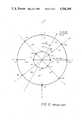
- While a single line of actuators such as illustrated in FIG. 1may at least theoretically be employed for certain limited uses to tip the mirror back and forth only about a single axis, generally rings of actuators of FIG. 2 are positioned beneath the mirror, such actuators having upper surfaces thereof affixed to the lower mirror surface as in FIG. 1, so that the mirror axis 24' may be pointed in any direction.
- actuators 11 and 21are positioned on radial line 31
- actuators 13 and 23are positioned along radial line 32
- actuators 15 and 25are positioned along radial line 33
- actuators 17 and 27are positioned along radial line 34.
- actuators 12 and 22are positioned along radial line 36
- actuators 14 and 24are positioned along radial line 37
- actuators 16 and 26are positioned along radial line 38
- actuators 18 and 28are positioned along radial line 39.
- the actuators in the first or inner ringare assigned the tens digit 1
- actuators in the second ringare assigned the tens digit 2
- the units digit, such as 1 in actuator 21indicates that the actuator is in the first group extending along radial line 31 along with actuator 11.
- radial line 37for example, intersects actuators 14 and 24 which form the fourth group. In the illustrated example of FIG.
- the actuator arrangement in FIG. 2illustrates the prior art configuration of an array of actuators. Only two rings have been illustrated in the interest of simplicity and will suffice to support an appropriate explanation of the nature of the array.
- a positive going control signalwould be applied to actuator 11 having a given value, whereas a larger control voltage would be applied to actuator 21 so as to move the mirror portion at 21 to a greater extent relative to that portion of the mirror affixed to actuator 11.
- actuator 15would cause an opposite displacement of the mirror portion adjacent 15, and actuator 25 would cause an even greater displacement of the portion adjacent 25 in an opposite direction, so that four different control voltages would be applied to the four transducers for actuators 11, 21, 15 and 25.
- the four control voltages and associated driversare reduced in number by applying a single, e.g., a positive going control voltage, to actuators 11 and 21 and applying a single negative control voltage to actuators 15 and 25; or, for the reversed wiring polarity case mentioned above, a single positive going control voltage to all actuators.
- the dual polarity aspect discussed beforeenables the push-pull operation of the optical element in one direction or the other depending upon the applied voltage polarity whereas the degree of change in direction is a function of the magnitude of the voltage applied to all actuators in any given group along this particular radial line.
- the maximum voltagewould be applied to the outermost actuators and lesser voltages would be applied to those actuators closer and closer to the central mirror portions. For lesser amounts of rotation, lesser voltages would of course be applied.
- the maximum voltage V ois defined as equal to the maximum deflection called for divided by the sensitivity or responsiveness of the edge actuator, in microns of displacement/volt. In the special case of rotation about the horizontal radial lines 32 and 34, V 21 .
- V ocould for example equal plus 100 volts and the voltage applied to actuator 11 would also be 100 volts since a lesser number of piezo-electric layers are connected to the driver applying 100 volts to actuator 21.
- the voltage applied to actuator 25could be minus 100 volts to effect a complimentary opposite displacement, whereas the voltage applied to actuator 15 would also be 100 volts since a lesser number of piezo-electric layers are conncted to the voltage source.
- V 22 and V 28would be, for example, positive and equal to V 21 cos theta (assuming all radial lines are angularly displaced from each other by equal angles) whereas V 24 and V 26 would be equal to V 25 cos theta and would of course be negative.
- the voltage patternwould be rotated 90° , such that the voltages previously applied to actuators 11 and 21 would now be applied to actuators 13 and 23 and so forth.
- rotation for a given positional commandcould be about some axis perpendicular to line 41, for example, displaced angularly from line 31 by some angle phi shown in FIG. 2.
- This voltage for the general caseequals V o cos (n theta-phi) where n is the number of the radial line starting with 36, and theta is the angular separation between radial lines.
Landscapes
- Physics & Mathematics (AREA)
- General Physics & Mathematics (AREA)
- Optics & Photonics (AREA)
- Mechanical Light Control Or Optical Switches (AREA)
Abstract
Description
Claims (27)
Priority Applications (1)
| Application Number | Priority Date | Filing Date | Title |
|---|---|---|---|
| US06/588,589US4588268A (en) | 1984-03-12 | 1984-03-12 | Tip-tilt mirror actuation system having simplified driver circuitry |
Applications Claiming Priority (1)
| Application Number | Priority Date | Filing Date | Title |
|---|---|---|---|
| US06/588,589US4588268A (en) | 1984-03-12 | 1984-03-12 | Tip-tilt mirror actuation system having simplified driver circuitry |
Publications (1)
| Publication Number | Publication Date |
|---|---|
| US4588268Atrue US4588268A (en) | 1986-05-13 |
Family
ID=24354479
Family Applications (1)
| Application Number | Title | Priority Date | Filing Date |
|---|---|---|---|
| US06/588,589Expired - LifetimeUS4588268A (en) | 1984-03-12 | 1984-03-12 | Tip-tilt mirror actuation system having simplified driver circuitry |
Country Status (1)
| Country | Link |
|---|---|
| US (1) | US4588268A (en) |
Cited By (15)
| Publication number | Priority date | Publication date | Assignee | Title |
|---|---|---|---|---|
| US4655560A (en)* | 1985-08-05 | 1987-04-07 | United Technologies Corporation | Demagnetization compensated deformable magnetostrictive mirror |
| US4944580A (en)* | 1988-07-27 | 1990-07-31 | Thermo Electron Technologies Corp. | Active segmented mirror including a plurality of piezoelectric drivers |
| WO1993008609A1 (en)* | 1991-10-18 | 1993-04-29 | Aura Systems, Inc. | Piezoelectric and electrostrictive actuators |
| WO1993025929A1 (en)* | 1992-06-08 | 1993-12-23 | United Technologies Corporation | Coaxial integrated deformable mirror actuator/retraction arrangement |
| US5359252A (en)* | 1993-03-30 | 1994-10-25 | The United States Of America As Represented By The United States Department Of Energy | Lead magnesium niobate actuator for micropositioning |
| EP0642048A1 (en)* | 1993-09-04 | 1995-03-08 | Carl Zeiss | Mirror support system with load cells |
| GB2299873A (en)* | 1996-01-23 | 1996-10-16 | David Scanlan | Steerable image display device |
| US6464364B2 (en)* | 2000-01-27 | 2002-10-15 | Aoptix Technologies, Inc. | Deformable curvature mirror |
| US20030107828A1 (en)* | 2000-01-27 | 2003-06-12 | Graves J. Elon | Deformable curvature mirror with unipolar wiring |
| US6721510B2 (en) | 2001-06-26 | 2004-04-13 | Aoptix Technologies, Inc. | Atmospheric optical data transmission system |
| US20040141752A1 (en)* | 2003-01-16 | 2004-07-22 | Shelton J. Christopher | Free space optical communication system with power level management |
| US7289736B1 (en) | 2003-01-13 | 2007-10-30 | Aoptix Technologies | Adaptive optics imaging system with object acquisition capability |
| US20070258158A1 (en)* | 2006-05-08 | 2007-11-08 | Sony Corporation | Deformable mirror device |
| US20080278789A1 (en)* | 2007-05-09 | 2008-11-13 | Funai Electric Co., Ltd. | Variable shape mirror and optical pickup device |
| US20140285880A1 (en)* | 2013-03-19 | 2014-09-25 | Goodrich Corporation | High correctability deformable mirror |
Citations (3)
| Publication number | Priority date | Publication date | Assignee | Title |
|---|---|---|---|---|
| US4128309A (en)* | 1975-08-19 | 1978-12-05 | Thomson-Brandt | Automatic optical focusing device |
| US4257686A (en)* | 1978-12-14 | 1981-03-24 | Itek Corporation | Multiple layer piezoelectric wavefront modulator |
| US4298247A (en)* | 1979-04-04 | 1981-11-03 | Quantel S.A. | Thick optical element having a variable curvature |
- 1984
- 1984-03-12USUS06/588,589patent/US4588268A/ennot_activeExpired - Lifetime
Patent Citations (3)
| Publication number | Priority date | Publication date | Assignee | Title |
|---|---|---|---|---|
| US4128309A (en)* | 1975-08-19 | 1978-12-05 | Thomson-Brandt | Automatic optical focusing device |
| US4257686A (en)* | 1978-12-14 | 1981-03-24 | Itek Corporation | Multiple layer piezoelectric wavefront modulator |
| US4298247A (en)* | 1979-04-04 | 1981-11-03 | Quantel S.A. | Thick optical element having a variable curvature |
Non-Patent Citations (2)
| Title |
|---|
| Pearson et al., "Experimental Studies of a Deformable Adaptive Optical System", J. Opt. Soc. Am., vol. 67, No. 3, Mar. '77. |
| Pearson et al., Experimental Studies of a Deformable Adaptive Optical System , J. Opt. Soc. Am., vol. 67, No. 3, Mar. 77.* |
Cited By (21)
| Publication number | Priority date | Publication date | Assignee | Title |
|---|---|---|---|---|
| US4655560A (en)* | 1985-08-05 | 1987-04-07 | United Technologies Corporation | Demagnetization compensated deformable magnetostrictive mirror |
| US4944580A (en)* | 1988-07-27 | 1990-07-31 | Thermo Electron Technologies Corp. | Active segmented mirror including a plurality of piezoelectric drivers |
| WO1993008609A1 (en)* | 1991-10-18 | 1993-04-29 | Aura Systems, Inc. | Piezoelectric and electrostrictive actuators |
| WO1993025929A1 (en)* | 1992-06-08 | 1993-12-23 | United Technologies Corporation | Coaxial integrated deformable mirror actuator/retraction arrangement |
| US5357825A (en)* | 1992-06-08 | 1994-10-25 | United Technologies Corporation | Coaxial integrated deformable mirror actuator/retraction arrangement |
| US5359252A (en)* | 1993-03-30 | 1994-10-25 | The United States Of America As Represented By The United States Department Of Energy | Lead magnesium niobate actuator for micropositioning |
| EP0642048A1 (en)* | 1993-09-04 | 1995-03-08 | Carl Zeiss | Mirror support system with load cells |
| GB2299873A (en)* | 1996-01-23 | 1996-10-16 | David Scanlan | Steerable image display device |
| US6874897B2 (en) | 2000-01-27 | 2005-04-05 | Aoptix Technologies, Inc. | Deformable curvature mirror with unipolar-wiring |
| US6464364B2 (en)* | 2000-01-27 | 2002-10-15 | Aoptix Technologies, Inc. | Deformable curvature mirror |
| US20030107828A1 (en)* | 2000-01-27 | 2003-06-12 | Graves J. Elon | Deformable curvature mirror with unipolar wiring |
| US6721510B2 (en) | 2001-06-26 | 2004-04-13 | Aoptix Technologies, Inc. | Atmospheric optical data transmission system |
| US20040156638A1 (en)* | 2001-06-26 | 2004-08-12 | Graves J. Elon | Atmospheric optical data transmission system |
| US7289736B1 (en) | 2003-01-13 | 2007-10-30 | Aoptix Technologies | Adaptive optics imaging system with object acquisition capability |
| US20040141752A1 (en)* | 2003-01-16 | 2004-07-22 | Shelton J. Christopher | Free space optical communication system with power level management |
| US7286766B2 (en) | 2003-01-16 | 2007-10-23 | Aoptix Technologies, Inc. | Free space optical communication system with power level management |
| US20070258158A1 (en)* | 2006-05-08 | 2007-11-08 | Sony Corporation | Deformable mirror device |
| US7837341B2 (en)* | 2006-05-08 | 2010-11-23 | Sony Corporation | Deformable mirror device |
| US20080278789A1 (en)* | 2007-05-09 | 2008-11-13 | Funai Electric Co., Ltd. | Variable shape mirror and optical pickup device |
| US20140285880A1 (en)* | 2013-03-19 | 2014-09-25 | Goodrich Corporation | High correctability deformable mirror |
| US9314980B2 (en)* | 2013-03-19 | 2016-04-19 | Goodrich Corporation | High correctability deformable mirror |
Similar Documents
| Publication | Publication Date | Title |
|---|---|---|
| US4588268A (en) | Tip-tilt mirror actuation system having simplified driver circuitry | |
| EP1471372B1 (en) | Shape-variable mirror and light control device having the shape-variable mirror | |
| US6327120B1 (en) | Actuator using piezoelectric element and head-positioning mechanism using the actuator | |
| US4736132A (en) | Piezoelectric deformable mirrors and gratings | |
| US6744173B2 (en) | Multi-layer, self-aligned vertical combdrive electrostatic actuators and fabrication methods | |
| US7423794B2 (en) | Device and method for stacked multi-level uncoupled electrostatic actuators | |
| US5579149A (en) | Miniature network of light obturators | |
| EP1130442B1 (en) | Optical switches using dual axis micromirrors | |
| US5083056A (en) | Displacement generating apparatus | |
| US5159225A (en) | Piezoelectric actuator | |
| US6593677B2 (en) | Biased rotatable combdrive devices and methods | |
| EP0567617B1 (en) | Piezoelectric and electrostrictive actuators | |
| US4533219A (en) | Tip-tilt mirror actuation system employing a single control voltage | |
| US20010051014A1 (en) | Optical switch employing biased rotatable combdrive devices and methods | |
| US4280756A (en) | Piezoelectric bi-morph mirror actuator | |
| KR100363066B1 (en) | E-block head stack microactuator assembly | |
| US6046527A (en) | Ultrasonic positioner with multiple degrees of freedom of movement | |
| US20060050421A1 (en) | Adaptive mirror system | |
| EP1088250A1 (en) | Very large angle integrated optical scanner made with an array of piezoelectric monomorphs | |
| US20060050419A1 (en) | Integrated wavefront correction module | |
| US6288985B1 (en) | Microactuator for fine tracking in a magneto-optical drive | |
| CA2478213C (en) | Method and apparatus for actuation of a two-axis mems device using three actuation elements | |
| US20020118910A1 (en) | Light deflector and method for driving light deflector | |
| JPH07270691A (en) | Mirror deflector | |
| JPH0334383A (en) | Laminated ceramic piezoelectric actuator |
Legal Events
| Date | Code | Title | Description |
|---|---|---|---|
| AS | Assignment | Owner name:ITEK CORPORATION, 10 MAGUIRE ROAD, LEXINGTON, MA 0 Free format text:ASSIGNMENT OF ASSIGNORS INTEREST.;ASSIGNOR:ALDRICH, RALPH E.;REEL/FRAME:004240/0015 Effective date:19840306 | |
| FEPP | Fee payment procedure | Free format text:PAYOR NUMBER ASSIGNED (ORIGINAL EVENT CODE: ASPN); ENTITY STATUS OF PATENT OWNER: LARGE ENTITY | |
| STCF | Information on status: patent grant | Free format text:PATENTED CASE | |
| FPAY | Fee payment | Year of fee payment:4 | |
| FPAY | Fee payment | Year of fee payment:8 | |
| AS | Assignment | Owner name:HUGHES DANBURY OPTICAL SYSTEMS, INC., CONNECTICUT Free format text:ASSIGNMENT OF ASSIGNORS INTEREST;ASSIGNOR:LITTON SYSTEMS, INC.;REEL/FRAME:007945/0794 Effective date:19960216 | |
| FPAY | Fee payment | Year of fee payment:12 | |
| AS | Assignment | Owner name:RAYTHEON COMPANY, A CORPORATION OF DELAWARE, MASSA Free format text:MERGER;ASSIGNOR:RAYTHEON OPTICAL SYSTEMS, INC., A CORPORATION OF DELAWARE;REEL/FRAME:010909/0671 Effective date:19981229 Owner name:RAYTHEON OPTICAL SYSTEMS, INC., A CORPORATION OF D Free format text:CHANGE OF NAME;ASSIGNOR:HUGHES DANBURY OPTICAL SYSTEMS, INC., A CORPORATION OF DELAWARE;REEL/FRAME:010909/0666 Effective date:19971217 | |
| AS | Assignment | Owner name:B.F. GOODRICH COMPANY, THE, NORTH CAROLINA Free format text:ASSIGNMENT OF ASSIGNORS INTEREST;ASSIGNOR:RAYTHEON COMPANY;REEL/FRAME:011497/0102 Effective date:20001227 |