US4587910A - Workpiece holding device for automatic sewing - Google Patents
Workpiece holding device for automatic sewingDownload PDFInfo
- Publication number
- US4587910A US4587910AUS06/646,810US64681084AUS4587910AUS 4587910 AUS4587910 AUS 4587910AUS 64681084 AUS64681084 AUS 64681084AUS 4587910 AUS4587910 AUS 4587910A
- Authority
- US
- United States
- Prior art keywords
- cover plate
- sharp
- workpiece holder
- base plate
- pins
- Prior art date
- Legal status (The legal status is an assumption and is not a legal conclusion. Google has not performed a legal analysis and makes no representation as to the accuracy of the status listed.)
- Expired - Fee Related
Links
- 238000009958sewingMethods0.000titleclaimsabstractdescription43
- 230000002452interceptive effectEffects0.000claims1
- 238000013459approachMethods0.000description5
- 230000002093peripheral effectEffects0.000description3
- 239000013013elastic materialSubstances0.000description2
- 229920001971elastomerPolymers0.000description2
- 210000003127kneeAnatomy0.000description2
- 239000000853adhesiveSubstances0.000description1
- 230000001070adhesive effectEffects0.000description1
- 239000004744fabricSubstances0.000description1
- 229920001821foam rubberPolymers0.000description1
- 239000010985leatherSubstances0.000description1
- 239000000463materialSubstances0.000description1
- 210000004417patellaAnatomy0.000description1
Images


Classifications
- D—TEXTILES; PAPER
- D05—SEWING; EMBROIDERING; TUFTING
- D05B—SEWING
- D05B39/00—Workpiece carriers
- D—TEXTILES; PAPER
- D05—SEWING; EMBROIDERING; TUFTING
- D05D—INDEXING SCHEME ASSOCIATED WITH SUBCLASSES D05B AND D05C, RELATING TO SEWING, EMBROIDERING AND TUFTING
- D05D2209/00—Use of special materials
- D05D2209/08—Use of special materials elastic, e.g. rubber spring
Definitions
- This inventionrelates to the holding of workpieces that are to be sewn by an automatic sewing machine.
- this inventionrelates to the registering of a workpiece within a workpiece holder so that it may be sewn by the automatic stitching machine.
- U.S. Pat. No. 3,988,993 to Robert V. Brophydiscloses a workpiece holding arrangement for use with automatic sewing machines.
- the workpiece holding arrangementconsists of a book pallet having hinged leaves that are used to orient and locate several pieces of work which are to be sewn together.
- each leaf of the book palletcontains one or more cavities that orient and accurately register the pieces of work that are to be sewn with respect to each other.
- the book palletis connected to a high resolution positioning system which accurately positions the pieces of work relative to a reciprocating sewing needle.
- a workpiece holding arrangementhaving a base plate with a plurality of sharp pins extending upwardly therefrom.
- a base piece of a workpiecewhich may be elastic, is positioned over all of the sharp pins. The number and spacing of the pins is such as to maintain the base piece in a stretched and flat position.
- a subset of these pinsis located around the periphery of at least one opening in the base plate which is covered when the base piece of the work has been positioned.
- a second piece of workwhich may also be elastic, is now positioned over the subset of pins located around the periphery of the opening.
- a second plate, preferably hinged to the base plateis now pivoted downwardly over the positioned pieces of work.
- the second platehas a plurality of holes therein which allow the sharp locating pins extending upwardly from the base plate to project therethrough.
- the second platemoreover has separate shields associated with each projecting pin so as to guard against any undesirable contact therewith during the subsequent handling of the workpiece holding arrangement.
- the operatortakes the workpiece holder and attaches it to a positioning apparatus of an automatic sewing machine.
- the accurately registered pieces of work within the workpiece holderare successively positioned under the reciprocating sewing needle which sews the pieces of work together.
- the shields mounted to the cover platedo not interfere with the needle as the workpiece holder is being moved by the positioning apparatus during automatic sewing.
- the workpiece holdermay be subsequently removed from the sewing machine and opened so as to remove the joined pieces. It is to be appreciated that all such handling of the workpiece holder can be accomplished without concern for the sharp points of the locating pins which remain shielded.
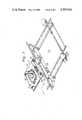
- FIG. 1is a perspective view of a workpiece holder in an open position with a workpiece located therein;
- FIG. 2is a view of the workpiece holder of FIG. 1 connected to positioning apparatus of an automatic sewing machine;
- FIG. 3is an exploded view of the workpiece holder and workpiece.
- FIG. 4is a detailed showing of a shield element appearing on the top cover plate of the workpiece holder.
- a workpiece holder 10is illustrated in an open position with a workpiece 12 located therein.
- the workpiece 12is held in place by a number of sharp pointed pins which extend upwardly from a base plate 14.
- a cover plate 16is pivotally attached via a set of hinges 18 and 20 to the base plate 14.
- the cover plate 16pivots downwardly over the base plate and is latched thereto by a pair of slideable latches (such as latch 22) which engage posts (such as post 24).
- the series of sharp pointed pinsextend upwardly through holes in the cover plate 16 at this time. These pins are shielded by individual shield devices mounted to the top of the cover plate.
- the workpiece 12, located within the closed workpiece holder 10is now ready for further processing. In this regard, a person picks up the workpiece holder 10 and connects it to the positioning apparatus of an automatic sewing machine.
- the workpiece holder 10is generally illustrated relative to a positioning apparatus 26 of an automatic sewing machine.
- the positioning apparatusincludes a moveable carriage 28 having a shelf 30 which receives the workpiece holder 10.
- the workpiece holder 10has a registration slot 32 and a registration hole 34. These are located over registration posts 36 and 38 extending upwardly from the shelf 30 of the movable carriage 28.
- the thus registered workpiece holdermay be secured by any convenient means such as clamps or threadable devices.
- the workpiece holder 10is now in a plane defined by the shelf 30 and the bed (not shown) of a stationary automatic sewing machine.
- the workpiece holder 10is movable in the indicated X and Y directions of movement by the positioning apparatus so as to present the workpiece 12 under a reciprocating sewing needle 38 associated with the stationary head of the automatic sewing machine. It is to be appreciated that the degree of accuracy in presenting the workpiece for sewing is premised in part upon the accurate registration of the workpiece within the workpiece holder 10.
- FIG. 3is an exploded view of both the workpiece holder 10 and the workpiece 12.
- the various portions of the workpiece 12are situated between the base plate 14 and the cover plate 16.
- the workpiece 12is seen to comprise: a bottom piece 40, an intermediate set of pieces 42 and 44 plus a top piece 46.
- the workpiece 12will eventually become an elastic support for a human knee.
- the bottom piece 40 and the top piece 46are made from conventional elastic materials normally found in elastic knee supports.
- the intermediate pieces 42 and 44are foam rubber parts having a thickness of approximately four tenths (0.4) of an inch .
- the piece 44approximates the size of a knee cap and fits within the hole in the piece 42.
- the pieces 40, 42, 44 and 46are positioned within the pallet 10 by structure which will now be described.
- a plurality of sharp pointed registration pinssuch as pin 48 are located around the periphery of a relatively large opening 50.
- the size and shape of the opening 50is such as to allow the sewing needle 38 to pass therethrough when stitching the various pieces of the workpiece.
- the registration pins such as 48are preferably spaced around the periphery of the opening at a spacing between successive pins of seventh-eighths (7/8) of an inch.
- the base plate 14has at least two further sharp pointed pins 52 and 54 that are located away from the periphery of the opening 50. The location of the pins 52 and 54 is such as to allow for the registration of two corners of the bottom piece 40.
- the base plate 14also has an edge gauge 56 which conforms to a mid-portion 58 of one edge of the bottom piece 40. This allows the mid-portion 58 of the bottom piece to be aligned with respect to a fixed location on the base plate before engagement with any of the sharp pointed pins.
- the thus aligned bottom pieceis smoothed and slightly stretched so as to allow the two corners of the bottompiece 40 to be registered on pins 52 and 54. Following engagement of the pins 52 and 54, the remainder of the piece 40 is smoothed and stretched over the registration pins located around the opening 50.
- the intermediate piecesare next temporarily affixed to the bottom piece 40. In this regard the intermediate pieces are preferably backed with adhesive so as to allow for a temporary adherence to a specific location on the bottom piece.
- the top piece 46is aligned with respect to the pattern of registration pins 48 located around the cut-out hole 50. The top piece is thereafter fitted down over this pattern of registration pins.
- the cover plate 16is now ready to be rotated downwardly over the thus located pieces on the base plate.
- the cover platehas a hole 60 of the same size and shape as the hole 50 in the bottom plate. This allows the appropriate portion of the workpiece 12 to be exposed for sewing.
- the sharp pointed registration pins 48will extend through holes such as 62 in the cover plate.
- Each holemust be precisely aligned with a respective registration pin so as to avoid any interference with the cover plate when it closes over the base plate.
- Thisrequires an accurate hinged connection to the base plate.
- an alignment block 64is located between the location holes for the hinges 18 and 20.
- a notch 66 in the cover plateassures that the cover plate will always be accurately registered with respect to the alignment block. This prevents any lateral looseness of the hinges 18 and 20 from affecting the positioning of the cover plate 16 with respect to the base plate.
- each hole receiving a registration pinhas a shield 68 assoclated therewith.
- the shield 68is illustrated in detail in FIG. 4.
- the shield 68is seen to comprise a rivoted element that extends upwardlv and thereafter outwardly over the registration pin 48 extending through the hole 62.
- the sharp point of the registration pin 48is completely covered by the cantilevered, outwardly extending portion of the shield 68.
- the outwardly extending portionis spaced above the point of the registration pin. This spacing must be sufficient to allow the cover plate 16 to cover over the base plate without a workpiece 12 being present.
- each shield 68 above the cover plate surfaceis preferably one quarter (0.250) of an inch.
- a peripheral edge 70 of the opening 60 in the cover plateis illustrated relative to the shield 68 and pin 48.
- This peripheral edge 70is only a short distance from the pin 48 as can be appreciated by referring to FIG. 3.
- a thickness of rubber 72is affixed to the underside of the cover plate 16 near the peripheral edge 70. This thickness of rubber extends around the entire periphery of the opening 60. This produces a local clamping pressure immediate to the sewing path of the needle 38.
Landscapes
- Engineering & Computer Science (AREA)
- Textile Engineering (AREA)
- Sewing Machines And Sewing (AREA)
Abstract
Description
Claims (13)
Priority Applications (1)
| Application Number | Priority Date | Filing Date | Title |
|---|---|---|---|
| US06/646,810US4587910A (en) | 1984-09-04 | 1984-09-04 | Workpiece holding device for automatic sewing |
Applications Claiming Priority (1)
| Application Number | Priority Date | Filing Date | Title |
|---|---|---|---|
| US06/646,810US4587910A (en) | 1984-09-04 | 1984-09-04 | Workpiece holding device for automatic sewing |
Publications (1)
| Publication Number | Publication Date |
|---|---|
| US4587910Atrue US4587910A (en) | 1986-05-13 |
Family
ID=24594562
Family Applications (1)
| Application Number | Title | Priority Date | Filing Date |
|---|---|---|---|
| US06/646,810Expired - Fee RelatedUS4587910A (en) | 1984-09-04 | 1984-09-04 | Workpiece holding device for automatic sewing |
Country Status (1)
| Country | Link |
|---|---|
| US (1) | US4587910A (en) |
Cited By (15)
| Publication number | Priority date | Publication date | Assignee | Title |
|---|---|---|---|---|
| US4763587A (en)* | 1987-06-30 | 1988-08-16 | Frye Ricky J | Work holder for sewing machines |
| US4870917A (en)* | 1987-06-30 | 1989-10-03 | Mim Industries, Inc. | Work holder for sewing machines |
| US4981092A (en)* | 1989-11-17 | 1991-01-01 | R. G. Barry Corporation | Fabric clamping device for embroidery machines |
| US5074230A (en)* | 1989-10-27 | 1991-12-24 | Brother Kogyo Kabushiki Kaisha | Workpiece fabric holding device for use in sewing machine |
| US5144899A (en)* | 1991-03-14 | 1992-09-08 | Allen Michael N | Combination embroidery/screen printing apparatus and method |
| WO1992017632A1 (en)* | 1991-03-28 | 1992-10-15 | Mim Industries, Inc. | Workpiece pallet having a detachable workpiece holder |
| US5193470A (en)* | 1991-11-07 | 1993-03-16 | British United Shoe Machinery Limited | Cording and workpiece holder for automatic stitching machines |
| US5375543A (en)* | 1993-04-30 | 1994-12-27 | Alliedsignal Inc. | Material holding frame system |
| WO1995034705A1 (en)* | 1994-06-10 | 1995-12-21 | Mutual Holdings Inc. | Fabric securing device including adhesive material |
| US5560309A (en)* | 1992-08-24 | 1996-10-01 | Mim Industries, Inc. | Material handling system |
| US20060180066A1 (en)* | 2005-01-28 | 2006-08-17 | Brother Kogyo Kabushiki Kaisha | Embroidery frame |
| US20100018447A1 (en)* | 2008-04-23 | 2010-01-28 | Holecek Arin N | Methods and apparatuses for assembly of a pericardial prosthetic heart valve |
| US9194070B2 (en)* | 2013-06-27 | 2015-11-24 | Brother Kogyo Kabushiki Kaisha | Embroidery frame and sewing machine |
| US9708738B2 (en) | 2013-06-27 | 2017-07-18 | Brother Kogyo Kabushiki Kaisha | Embroidery frame and sewing machine |
| US11236449B2 (en)* | 2018-05-31 | 2022-02-01 | Nike, Inc. | Stitching system for a shoe upper |
Citations (6)
| Publication number | Priority date | Publication date | Assignee | Title |
|---|---|---|---|---|
| US1092038A (en)* | 1913-05-29 | 1914-03-31 | Emil Curtis Gerber | Work-holder. |
| US1251677A (en)* | 1915-07-28 | 1918-01-01 | John I Mcdonald | Templet for the manufacture of cuffs. |
| US2094528A (en)* | 1934-05-23 | 1937-09-28 | Charles G Daughters | Automatic means for stitching pockets and the like |
| US3034458A (en)* | 1958-09-19 | 1962-05-15 | Clarkson Textiles Ltd | Stitching of materials |
| FR1525794A (en)* | 1966-06-10 | 1968-05-17 | Automatic embroidery machine | |
| US3599583A (en)* | 1967-06-16 | 1971-08-17 | Icchok Majer Berman | Automatic sewing machine |
- 1984
- 1984-09-04USUS06/646,810patent/US4587910A/ennot_activeExpired - Fee Related
Patent Citations (6)
| Publication number | Priority date | Publication date | Assignee | Title |
|---|---|---|---|---|
| US1092038A (en)* | 1913-05-29 | 1914-03-31 | Emil Curtis Gerber | Work-holder. |
| US1251677A (en)* | 1915-07-28 | 1918-01-01 | John I Mcdonald | Templet for the manufacture of cuffs. |
| US2094528A (en)* | 1934-05-23 | 1937-09-28 | Charles G Daughters | Automatic means for stitching pockets and the like |
| US3034458A (en)* | 1958-09-19 | 1962-05-15 | Clarkson Textiles Ltd | Stitching of materials |
| FR1525794A (en)* | 1966-06-10 | 1968-05-17 | Automatic embroidery machine | |
| US3599583A (en)* | 1967-06-16 | 1971-08-17 | Icchok Majer Berman | Automatic sewing machine |
Cited By (23)
| Publication number | Priority date | Publication date | Assignee | Title |
|---|---|---|---|---|
| US4763587A (en)* | 1987-06-30 | 1988-08-16 | Frye Ricky J | Work holder for sewing machines |
| US4870917A (en)* | 1987-06-30 | 1989-10-03 | Mim Industries, Inc. | Work holder for sewing machines |
| US5074230A (en)* | 1989-10-27 | 1991-12-24 | Brother Kogyo Kabushiki Kaisha | Workpiece fabric holding device for use in sewing machine |
| US4981092A (en)* | 1989-11-17 | 1991-01-01 | R. G. Barry Corporation | Fabric clamping device for embroidery machines |
| US5144899A (en)* | 1991-03-14 | 1992-09-08 | Allen Michael N | Combination embroidery/screen printing apparatus and method |
| US5427043A (en)* | 1991-03-28 | 1995-06-27 | Mim Industries, Inc. | Workpiece pallet having a detachable workpiece holder and method of sewing a workpiece |
| US5632214A (en)* | 1991-03-28 | 1997-05-27 | Mim Industries, Inc. | Workpiece pallet having a detachable workpiece holder |
| WO1992017632A1 (en)* | 1991-03-28 | 1992-10-15 | Mim Industries, Inc. | Workpiece pallet having a detachable workpiece holder |
| US5421277A (en)* | 1991-03-28 | 1995-06-06 | Mim Industries, Inc. | Workpiece pallet having a detachable workpiece holder |
| ES2070685A2 (en)* | 1991-11-07 | 1995-06-01 | Usm Espana Sa | Cording and workpiece holder for automatic stitching machines |
| US5193470A (en)* | 1991-11-07 | 1993-03-16 | British United Shoe Machinery Limited | Cording and workpiece holder for automatic stitching machines |
| US5560309A (en)* | 1992-08-24 | 1996-10-01 | Mim Industries, Inc. | Material handling system |
| US5375543A (en)* | 1993-04-30 | 1994-12-27 | Alliedsignal Inc. | Material holding frame system |
| WO1995034705A1 (en)* | 1994-06-10 | 1995-12-21 | Mutual Holdings Inc. | Fabric securing device including adhesive material |
| US5546877A (en)* | 1994-06-10 | 1996-08-20 | Mutual Holdings Inc. | Fabric securing device including adhesive and needle lubrication |
| US20060180066A1 (en)* | 2005-01-28 | 2006-08-17 | Brother Kogyo Kabushiki Kaisha | Embroidery frame |
| US7255052B2 (en)* | 2005-01-28 | 2007-08-14 | Brother Kogyo Kabushiki Kaisha | Embroidery frame |
| US20100018447A1 (en)* | 2008-04-23 | 2010-01-28 | Holecek Arin N | Methods and apparatuses for assembly of a pericardial prosthetic heart valve |
| US8312825B2 (en)* | 2008-04-23 | 2012-11-20 | Medtronic, Inc. | Methods and apparatuses for assembly of a pericardial prosthetic heart valve |
| US8511244B2 (en) | 2008-04-23 | 2013-08-20 | Medtronic, Inc. | Methods and apparatuses for assembly of a pericardial prosthetic heart valve |
| US9194070B2 (en)* | 2013-06-27 | 2015-11-24 | Brother Kogyo Kabushiki Kaisha | Embroidery frame and sewing machine |
| US9708738B2 (en) | 2013-06-27 | 2017-07-18 | Brother Kogyo Kabushiki Kaisha | Embroidery frame and sewing machine |
| US11236449B2 (en)* | 2018-05-31 | 2022-02-01 | Nike, Inc. | Stitching system for a shoe upper |
Similar Documents
| Publication | Publication Date | Title |
|---|---|---|
| US4587910A (en) | Workpiece holding device for automatic sewing | |
| US3988993A (en) | Pallet for registering and securing a workpiece | |
| US3749038A (en) | Material folding and stitching aid | |
| US4357885A (en) | Fabric holding device for multi-head embroidery machines | |
| CA2288484A1 (en) | Alignment apparatus for tubular hooping device | |
| US4981092A (en) | Fabric clamping device for embroidery machines | |
| US3216383A (en) | Device for sewing trimmings | |
| US5396721A (en) | Tensioning device | |
| US3174447A (en) | Fabric holding device for automatic contoured sewing | |
| US5842430A (en) | Tubular hooping device for embroidery hoops | |
| US4706583A (en) | Template for embroidery machine | |
| US5443025A (en) | Multiple clamp system for a computer controlled sewing machine | |
| DE69325941D1 (en) | Clamping device or template guide and device for pre-positioning and moving a piece of fabric and for coupling it to a programmable sewing machine | |
| US3721202A (en) | Method of, and apparatus for, stitching together two layers of material | |
| US5636461A (en) | Visual aid device for stretching, aligning, and mounting needlepoint fabric | |
| US4175329A (en) | Attachment for motion translating machine | |
| US4679501A (en) | Registration device for use in silk screen printing | |
| US5193470A (en) | Cording and workpiece holder for automatic stitching machines | |
| US2879734A (en) | Portable bases for miniature sewing machines | |
| JP2545379Y2 (en) | Loading device with built-in device | |
| US2894468A (en) | Copying device for sewing-machine | |
| US2341441A (en) | Work holder for article-attaching machines | |
| US3871532A (en) | Workpieces moving apparatus | |
| CA1112949A (en) | Apparatus for holding work in a sewing machine | |
| US3182412A (en) | Device for stretching a plurality of fabric pieces on a fabric holding frame |
Legal Events
| Date | Code | Title | Description |
|---|---|---|---|
| AS | Assignment | Owner name:USM CORPORATION, 426 COLT HIGHWAY, FARMINGTON, CT. Free format text:ASSIGNMENT OF ASSIGNORS INTEREST.;ASSIGNOR:RAINES, MAX;REEL/FRAME:004306/0347 Effective date:19840828 | |
| AS | Assignment | Owner name:BUSM CO. LIMITED, ROSS WALK, BELGRAVE, LEICESTER L Free format text:ASSIGNMENT OF ASSIGNORS INTEREST.;ASSIGNOR:USM CORPORATION;REEL/FRAME:004761/0784 Effective date:19870430 Owner name:BRITISH UNITED SHOE MACHINERY LIMITED Free format text:CHANGE OF NAME;ASSIGNOR:BUSM CO. LIMITED;REEL/FRAME:004761/0879 Effective date:19870512 Owner name:BUSM CO. LIMITED,ENGLAND Free format text:ASSIGNMENT OF ASSIGNORS INTEREST;ASSIGNOR:USM CORPORATION;REEL/FRAME:004761/0784 Effective date:19870430 | |
| FEPP | Fee payment procedure | Free format text:PAYOR NUMBER ASSIGNED (ORIGINAL EVENT CODE: ASPN); ENTITY STATUS OF PATENT OWNER: LARGE ENTITY | |
| REMI | Maintenance fee reminder mailed | ||
| LAPS | Lapse for failure to pay maintenance fees | ||
| STCH | Information on status: patent discontinuation | Free format text:PATENT EXPIRED DUE TO NONPAYMENT OF MAINTENANCE FEES UNDER 37 CFR 1.362 | |
| FP | Lapsed due to failure to pay maintenance fee | Effective date:19900513 |