US4587601A - Combined flood and spot light incorporating a reflector member of circular and parabolic longitudinal cross section - Google Patents
Combined flood and spot light incorporating a reflector member of circular and parabolic longitudinal cross sectionDownload PDFInfo
- Publication number
- US4587601A US4587601AUS06/684,913US68491384AUS4587601AUS 4587601 AUS4587601 AUS 4587601AUS 68491384 AUS68491384 AUS 68491384AUS 4587601 AUS4587601 AUS 4587601A
- Authority
- US
- United States
- Prior art keywords
- reflector member
- lamp
- parabolic
- axis
- parabola
- Prior art date
- Legal status (The legal status is an assumption and is not a legal conclusion. Google has not performed a legal analysis and makes no representation as to the accuracy of the status listed.)
- Expired - Fee Related
Links
- 230000002093peripheral effectEffects0.000claimsabstract2
- 230000001795light effectEffects0.000description6
- 230000004048modificationEffects0.000description5
- 238000012986modificationMethods0.000description5
- 230000009977dual effectEffects0.000description4
- 239000011521glassSubstances0.000description4
- 239000004020conductorSubstances0.000description2
- 238000010276constructionMethods0.000description2
- 238000005476solderingMethods0.000description2
- 239000005341toughened glassSubstances0.000description2
- 238000003466weldingMethods0.000description2
- 241001622623CoeliadinaeSpecies0.000description1
- 238000005219brazingMethods0.000description1
- 230000000694effectsEffects0.000description1
- 230000001681protective effectEffects0.000description1
- 230000000717retained effectEffects0.000description1
Images


Classifications
- F—MECHANICAL ENGINEERING; LIGHTING; HEATING; WEAPONS; BLASTING
- F21—LIGHTING
- F21V—FUNCTIONAL FEATURES OR DETAILS OF LIGHTING DEVICES OR SYSTEMS THEREOF; STRUCTURAL COMBINATIONS OF LIGHTING DEVICES WITH OTHER ARTICLES, NOT OTHERWISE PROVIDED FOR
- F21V7/00—Reflectors for light sources
- F21V7/0025—Combination of two or more reflectors for a single light source
- F—MECHANICAL ENGINEERING; LIGHTING; HEATING; WEAPONS; BLASTING
- F21—LIGHTING
- F21S—NON-PORTABLE LIGHTING DEVICES; SYSTEMS THEREOF; VEHICLE LIGHTING DEVICES SPECIALLY ADAPTED FOR VEHICLE EXTERIORS
- F21S41/00—Illuminating devices specially adapted for vehicle exteriors, e.g. headlamps
- F21S41/10—Illuminating devices specially adapted for vehicle exteriors, e.g. headlamps characterised by the light source
- F21S41/14—Illuminating devices specially adapted for vehicle exteriors, e.g. headlamps characterised by the light source characterised by the type of light source
- F21S41/162—Incandescent light sources, e.g. filament or halogen lamps
- F—MECHANICAL ENGINEERING; LIGHTING; HEATING; WEAPONS; BLASTING
- F21—LIGHTING
- F21S—NON-PORTABLE LIGHTING DEVICES; SYSTEMS THEREOF; VEHICLE LIGHTING DEVICES SPECIALLY ADAPTED FOR VEHICLE EXTERIORS
- F21S41/00—Illuminating devices specially adapted for vehicle exteriors, e.g. headlamps
- F21S41/30—Illuminating devices specially adapted for vehicle exteriors, e.g. headlamps characterised by reflectors
- F21S41/32—Optical layout thereof
- F21S41/321—Optical layout thereof the reflector being a surface of revolution or a planar surface, e.g. truncated
- F—MECHANICAL ENGINEERING; LIGHTING; HEATING; WEAPONS; BLASTING
- F21—LIGHTING
- F21S—NON-PORTABLE LIGHTING DEVICES; SYSTEMS THEREOF; VEHICLE LIGHTING DEVICES SPECIALLY ADAPTED FOR VEHICLE EXTERIORS
- F21S41/00—Illuminating devices specially adapted for vehicle exteriors, e.g. headlamps
- F21S41/30—Illuminating devices specially adapted for vehicle exteriors, e.g. headlamps characterised by reflectors
- F21S41/32—Optical layout thereof
- F21S41/323—Optical layout thereof the reflector having two perpendicular cross sections having regular geometrical curves of a distinct nature
- F—MECHANICAL ENGINEERING; LIGHTING; HEATING; WEAPONS; BLASTING
- F21—LIGHTING
- F21S—NON-PORTABLE LIGHTING DEVICES; SYSTEMS THEREOF; VEHICLE LIGHTING DEVICES SPECIALLY ADAPTED FOR VEHICLE EXTERIORS
- F21S41/00—Illuminating devices specially adapted for vehicle exteriors, e.g. headlamps
- F21S41/30—Illuminating devices specially adapted for vehicle exteriors, e.g. headlamps characterised by reflectors
- F21S41/32—Optical layout thereof
- F21S41/36—Combinations of two or more separate reflectors
- F21S41/365—Combinations of two or more separate reflectors successively reflecting the light
- F—MECHANICAL ENGINEERING; LIGHTING; HEATING; WEAPONS; BLASTING
- F21—LIGHTING
- F21S—NON-PORTABLE LIGHTING DEVICES; SYSTEMS THEREOF; VEHICLE LIGHTING DEVICES SPECIALLY ADAPTED FOR VEHICLE EXTERIORS
- F21S41/00—Illuminating devices specially adapted for vehicle exteriors, e.g. headlamps
- F21S41/10—Illuminating devices specially adapted for vehicle exteriors, e.g. headlamps characterised by the light source
- F21S41/14—Illuminating devices specially adapted for vehicle exteriors, e.g. headlamps characterised by the light source characterised by the type of light source
- F21S41/162—Incandescent light sources, e.g. filament or halogen lamps
- F21S41/166—Incandescent light sources, e.g. filament or halogen lamps characterised by the shape of the filament
- F—MECHANICAL ENGINEERING; LIGHTING; HEATING; WEAPONS; BLASTING
- F21—LIGHTING
- F21V—FUNCTIONAL FEATURES OR DETAILS OF LIGHTING DEVICES OR SYSTEMS THEREOF; STRUCTURAL COMBINATIONS OF LIGHTING DEVICES WITH OTHER ARTICLES, NOT OTHERWISE PROVIDED FOR
- F21V7/00—Reflectors for light sources
- F21V7/0008—Reflectors for light sources providing for indirect lighting
- F—MECHANICAL ENGINEERING; LIGHTING; HEATING; WEAPONS; BLASTING
- F21—LIGHTING
- F21V—FUNCTIONAL FEATURES OR DETAILS OF LIGHTING DEVICES OR SYSTEMS THEREOF; STRUCTURAL COMBINATIONS OF LIGHTING DEVICES WITH OTHER ARTICLES, NOT OTHERWISE PROVIDED FOR
- F21V7/00—Reflectors for light sources
- F21V7/04—Optical design
- F21V7/09—Optical design with a combination of different curvatures
- F—MECHANICAL ENGINEERING; LIGHTING; HEATING; WEAPONS; BLASTING
- F21—LIGHTING
- F21W—INDEXING SCHEME ASSOCIATED WITH SUBCLASSES F21K, F21L, F21S and F21V, RELATING TO USES OR APPLICATIONS OF LIGHTING DEVICES OR SYSTEMS
- F21W2102/00—Exterior vehicle lighting devices for illuminating purposes
- F21W2102/30—Fog lights
Definitions
- This inventionrelates to a dual function light, more particularly to a light which can be used either as a spot light or a flood light separately or as both spot and flood light at the same time.
- the constructionuses a minimum quantity of components which are readily assembled to produce a high quality article at a low cost.
- the lighthas high utility in fire and police work because of the two types of beams available, although it is primarily intended for use on automobiles as a spot light and as a flood or fog light.
- U.S. Pat. No. 1,148,101 to Kush and U.S. Pat. No. 3,759,084 to PlewkaEach has a first reflector with a first lamp and a second reflector mounted in spaced relation concentrically within the first reflector and provided with its own lamp which is spaced axially forward of the first lamp.
- Kushthe idea is that the first lamp produces a dim light
- the second lampproduces a medium light and the two lamps together produce a bright light.
- the second lampproduces the usual bright driving light and the first lamp illuminates the surrounding area to reduce the dazzling effect of the second lamp. In both cases, all of the rays are emitted in random array and produce a flood light effect and consequently there is no way to produce an alternative spot light effect.
- a light for driving or other usewhich may be utilized as a spot light or a flood light or both at the same time with a single unit of great simplicity.
- itincludes a first, forwardly concave reflector member having a substantially parabolic cross section mounting means carried by the reflector member and extending to a point axially forward of the rear wall of the reflector member, and in a first, forward lamp carried by the mounting means in axially forwardly spaced relation to the rear wall of the first reflector member.
- a second, rearwardly concave reflector member having a substantially arcuate cross sectionis mounted in axially spaced relation forwardly of the first, forward lamp.
- a second, rearward lampis supported on the mounting means in axially spaced relation behind the first lamp and forward of the rear wall of the first member.
- the two reflector members and the two lampsare all arranged in axial alignment with each other.
- Typical switch meansare provided to selectively activate either or both of said lamps.
- the relative dimensions and locations of the components so far described with respect to each otherare so chosen that the rays emanating from the first, forward lamp will travel primarily forward to strike the second reflector member. There they will be reflected rearward to strike the first reflector member which will reflect them forward in substantially parallel array, providing a spot light effect. The rays emanating from the second, rearward lamp will travel primarily laterally to strike the first reflector member which will reflect them forward in random array, providing a flood light effect.
- each of the reflector memberscomprises a surface of revolution swung about the fore and aft axis of the axially spaced lamps so that they are circular in elevation.
- a circular transparent glass plateextends across the open end of the first reflector member and serves as a closure for the unit.
- the central portion of the plateis the same size and shape as the second reflector member which is mounted in the concavity of the plate, and the area around the second reflector member is the lens of the unit.
- the entire plateis preferably tempered glass.
- a shieldmay be mounted laterally of the rearward lamp to bar travel of its rays to that portion of the first reflector member behind the shield.
- the shieldmay take the form of a part of a cylinder having an axis extending fore and aft parallel to the axis of the lamp arrangement, and the inner surface of the shield may have a mirror finish to reflect the ray of the lamp to the opposite portion of the first reflector member.
- the first reflector memberis trough-shaped with a substantial lateral extent and with its parabolic cross section in a vertical plane extending fore and aft normal to its lateral extent
- the second reflector memberis also trough shaped with a substantial lateral extent and its arcuate cross section is in a vertical plane extending fore and aft normal to its lateral extent.
- the ends of the first reflector memberare cut at a forwardly diverging angle and its open ends are closed with correspondingly shaped plate members which intercept rays traveling laterally and direct them forwardly.
- the second reflector memberis also elongate it is supported in position by securing its ends to the angular plate members so that the two reflector members may be rigidly retained in parallel relation with each other.
- each of the lampsmay be so arranged on the mounting means that its filament will extend laterally.
- a light shieldmay be mounted close to the rearward lamp either above or below it to bar travel of the emitted light rays to the lower or upper portion of the first reflector member as may be desired.
- a further modificationis provided wherein the central portion of the first reflector is spherical, whereas the outer portion is parabolic.
- This modificationhas particular application for general use lights where both spot light and flood light capabilities are desired.
- FIG. 1is a front elevational view of the presently preferred embodiment of the light of this invention
- FIG. 2is an enlarged vertical sectional view of the light taken on line 2--2 of FIG. 1;
- FIG. 3is an elevational view, partly in section, taken on line 3--3 of FIG. 2;
- FIG. 4is a fragmentary; horizontal section, taken on line 4--4 of FIG. 1;
- FIG. 5is a front elevational view of a second embodiment of the light of this invention.
- FIG. 6is a horizontal sectional view taken on line 6--6 of FIG. 5;
- FIG. 7is a vertical sectional view taken on line 7--7 of FIG. 5;
- FIG. 8is a vertical section of a third embodiment of this invention.
- FIGS. 1 to 4The presently preferred construction of the light of this invention is illustrated in FIGS. 1 to 4, in which FIG. 1 shows that the light is basically circular in its frontal view.
- the major detailsare shown in the sectional view of FIG. 2, in which it will be seen that a first reflector member 10 is provided which is forwardly concave and which has a parabolic cross section in a vertical plane extending fore and aft and normal to its lateral expanse.
- the reflector memberis actually a parabolic surface of revolution swung about its fore and aft axis.
- Mounting means 12may be secured to the reflector member at any place in any suitable way but in the present case are shown as a pair of posts 14 secured to a base 16 and extending forwardly parallel to the axis of the reflector member.
- the latteris surrounded by a protective housing 18 having a forward free edge coterminous with the free edge of the reflector member and having a central opening 20 in its rear wall 22 registering with a central opening 24 in the rear wall of the reflector member.
- a tapered washer 26is interposed between the housing and the reflector, and the three are secured together by any suitable means such as soldering, brazing, welding or the like.
- the postsare extended through openings 20 and 24, and base 16 is secured to the assembly by suitable means.
- the posts 14carry a socket 28 in which is mounted a first, forwardly lamp 30 in axially forwardly spaced relation to the rear wall of the first reflector member 10.
- a second rearwardly concave reflector member 32having a substantially arcuate cross section is mounted in axially spaced relation forwardly of lamp 30.
- a circular transparent glass plate 34extends across the open end of the first reflector member 10 to serve as a closure for the unit and is held in place by frame 36.
- the annular outer portion or ring 38 of the plateserves as the lens for transmitting the light, while its central portion 40 is of the same size and shape as the second reflector member 32, and the reflector member is mounted in the concavity of portion 40.
- the plateis formed of tempered glass.
- a second socket 44is carried by posts 14 at a location in axially spaced relation behind socket 28 and forward of the rear wall of reflector member 10, and a second rearward lamp 46 is mounted in the socket.
- the rays 48 emanating from lamp 46travel primarily laterally to strike reflector member 10 which will reflect them forward in random array, providing a flood light effect.
- switches 50 and 52 of conventional designare interposed in conductors 54 and 56 which are connected to a suitable power supply. Either switch may be tripped separately to activate one or the other of the lamps or they both may be tripped at the same time to activate both lamps where desired.
- a shield 58may be mounted laterally of rearward lamp 46 by means of a bracket 60 connected to the first reflector member as shown in FIGS. 2, 3, and 4.
- the shieldmay take the form of a part of a cylinder having an axis extending fore and aft parallel to the axis of the lamp arrangement, and its inner surface may have a mirror finish to reflect the rays of the lamp to the opposite portion of the first reflector member, as indicated in FIG. 3.
- FIGS. 5, 6, and 7,A modification of the embodiment just described is illustrated in FIGS. 5, 6, and 7, in which it will be seen that the first reflector member 62 is trough-shaped with a substantial lateral extent but it still has a parabolic cross section in a vertical plane extending fore and aft normal to its lateral extent.
- the second reflector member 64is also trough-shaped with a substantial lateral extent and its arcuate cross section is in a vertical plane extending fore and aft normal to its lateral extent.
- the end portions 66 of member 62are cut at forwardly diverging angles and a pair of end plate members 68 are shaped to correspond to the end openings and are secured in place by any suitable means. Any light rays 70 emanating laterally to either side will be reflected forward as shown in FIG. 6.
- the second reflector member 64has its ends 72 cut at the same angle as the setting of end plate members 68 and it is secured directly to them by any suitable means such as soldering, welding, or the like.
- a glass cover plate 74closes the open side of the light and is held in place by frame 76.
- a plurality of support posts 78, 80 and 82are generally centrally mounted in the rear wall 84 of member 62 and carry a first, forward lamp 86 in a position spaced axially forward of rear wall 84, and a second, rearward lamp 88 spaced axially rearward of the first lamp and axially forward of wall 84.
- the second reflector member 64is spaced forward of lamp 86.
- Switches 90 and 92are interposed in conductors 94 and 96 which are connected to a suitable power source, and the switches may be used to activate the lamps separately or together as desired.
- each of the lampsis preferably mounted so that its filament extends laterally to increase the width of the beam of light projected forward.
- a light shield 98may be mounted above or below the rearward lamp 88 to bar travel of the emitted light rays to a selected portion of reflector member 62.
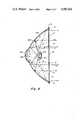
- FIG. 8A further alternative embodiment is shown in FIG. 8 in diagrammatical form.
- This embodimenthas particular application for a portable light which is to serve as either a flood or spot light.
- the first reflector 100has a spherical portion 102 at the center thereof surrounded by a parabolic portion 104, as shown.
- a first light source 106is positioned adjacent the spherical portion 102 and a second light source 108 is actually aligned with the first light source and is positioned adjacent a second spherical reflector 110.
- the front of reflector 100is closed by a lens or glass plate 112 which is held in place by a frame 114, as shown.
- the light from rear lamp 106will be reflected in a random pattern from the light either directly through the lens or off of the spherical portion 102 and reflector 100 to provide a flood light.
- the light from the forward lamp 108will be reflected, for the most part, off the parabolic surface 104 in a parallel pattern or will reflect from spherical mirror 100 onto parabolic surface 104 and hence in a parallel to provide a spot light.
- lamps 106 and 108may be mounted similarly to those shown in FIG. 2 and that the electrical circuitry would be similar to that described for the embodiment shown in FIG. 2.
- Graphical analysis of the drawing of FIG. 8can be used to establish the equations of the circle of the spherical portion 102, the parabola of the parabolic portion 104 and the circle of the second spherical reflector 110 in an X-Y Cartesian coordinate system.
- the X-Y coordinate systemlies in the single plane of reference shown in FIG. 8 and has an origin at the vertex of the parabolic portion 104.
- the positive Y axisextends from the vertex of the parabolic portion through the spherical portion and away therefrom, the Y axis being coincident with a longitudinal axis of the light.
- the X axistherefore is seen to extend perpendicularly therefrom.
- the circle in the X-Y coordinate system of the spherical portion 102has the equation:
- the parabola in the X-Y coordinate system of the parabolic portion 104has substantially the equation:
- the circle of the spherical portion 102 and parabola of the parabolic portion 104have points of intersection substantially at
- the circle in the X-Y coordinate system of the second spherical reflector 110has the equation:
Landscapes
- Engineering & Computer Science (AREA)
- General Engineering & Computer Science (AREA)
- Physics & Mathematics (AREA)
- Geometry (AREA)
- Non-Portable Lighting Devices Or Systems Thereof (AREA)
Abstract
Description
(X-0).sup.2 +(Y+0.700).sup.2 =1.0609 opening downward
X.sup.2 =-4.225Y opening downward
(X-0).sup.2 +(Y+1.05625).sup.2 =0.250 opening upward
Claims (8)
Priority Applications (1)
| Application Number | Priority Date | Filing Date | Title |
|---|---|---|---|
| US06/684,913US4587601A (en) | 1981-07-23 | 1984-12-21 | Combined flood and spot light incorporating a reflector member of circular and parabolic longitudinal cross section |
Applications Claiming Priority (2)
| Application Number | Priority Date | Filing Date | Title |
|---|---|---|---|
| US06/285,944US4755916A (en) | 1981-07-23 | 1981-07-23 | Combined flood and spot light |
| US06/684,913US4587601A (en) | 1981-07-23 | 1984-12-21 | Combined flood and spot light incorporating a reflector member of circular and parabolic longitudinal cross section |
Related Parent Applications (1)
| Application Number | Title | Priority Date | Filing Date |
|---|---|---|---|
| US06/285,944ContinuationUS4755916A (en) | 1981-07-23 | 1981-07-23 | Combined flood and spot light |
Publications (1)
| Publication Number | Publication Date |
|---|---|
| US4587601Atrue US4587601A (en) | 1986-05-06 |
Family
ID=26963482
Family Applications (1)
| Application Number | Title | Priority Date | Filing Date |
|---|---|---|---|
| US06/684,913Expired - Fee RelatedUS4587601A (en) | 1981-07-23 | 1984-12-21 | Combined flood and spot light incorporating a reflector member of circular and parabolic longitudinal cross section |
Country Status (1)
| Country | Link |
|---|---|
| US (1) | US4587601A (en) |
Cited By (27)
| Publication number | Priority date | Publication date | Assignee | Title |
|---|---|---|---|---|
| US4800468A (en)* | 1986-11-29 | 1989-01-24 | Stanley Electric Co., Ltd. | Headlamp for vehicle |
| US4897771A (en)* | 1987-11-24 | 1990-01-30 | Lumitex, Inc. | Reflector and light system |
| US5353203A (en)* | 1992-11-13 | 1994-10-04 | Robert Bosch Gmbh | Headlight for a vehicle |
| US5618102A (en)* | 1995-06-07 | 1997-04-08 | Adac Plastics, Inc. | Plasma discharge lamp |
| US5820253A (en)* | 1993-11-15 | 1998-10-13 | Delma Elektro- Und Medizinische Apparatebau Gesellschaft Mbh | Light for medical use |
| GB2337322A (en)* | 1998-05-14 | 1999-11-17 | Koito Mfg Co Ltd | Combined fog lamp and high beam lamp for vehicle headlamp |
| EP0860655A3 (en)* | 1997-02-21 | 2000-03-22 | Osram Sylvania Inc. | Lamp reflector for use with gaseous discharge lighting |
| US6280054B1 (en)* | 1999-07-02 | 2001-08-28 | Zight Corporation | Image generator having an improved illumination system |
| US6572234B1 (en)* | 1999-11-23 | 2003-06-03 | Heraeus Med Gmbh | Lamp, especially a surgery lamp, with at least two bulbs |
| US20030117798A1 (en)* | 2001-12-21 | 2003-06-26 | Leysath Joseph A. | Light emitting diode light fixture |
| US6641293B2 (en) | 2001-10-31 | 2003-11-04 | Visteon Global Technologies, Inc. | Light shield with reflective inner surface |
| US6666565B2 (en)* | 2002-03-29 | 2003-12-23 | Arista Enterprises Inc. | Light emitting diode (LED) flashlight |
| US6758582B1 (en)* | 2003-03-19 | 2004-07-06 | Elumina Technology Incorporation | LED lighting device |
| US6774545B1 (en) | 2000-11-09 | 2004-08-10 | General Electric Company | Reflector lamps |
| US20040179371A1 (en)* | 2002-12-24 | 2004-09-16 | Ichikoh Industries, Ltd. | Vehicle lamp |
| US20050018442A1 (en)* | 2003-07-23 | 2005-01-27 | Samlip Industrial Co., Ltd. | Vehicle lamp with a shield having a double directional illumination structure |
| US6871993B2 (en)* | 2002-07-01 | 2005-03-29 | Accu-Sort Systems, Inc. | Integrating LED illumination system for machine vision systems |
| US20050083674A1 (en)* | 2003-10-03 | 2005-04-21 | Hsin-Cheng Hong | Liquid crystal display and backlight module thereof |
| US20060109669A1 (en)* | 2004-11-24 | 2006-05-25 | Koito Manufacturing Co., Ltd. | Vehicle lighting device |
| WO2006092697A1 (en)* | 2005-03-01 | 2006-09-08 | Hd Developments (Proprietary) Limited | A lamp using a light emitting diode (led) as a light source |
| US20060285088A1 (en)* | 2005-06-17 | 2006-12-21 | Nobuyuki Kimura | Light source unit and projection type image display apparatus having the same |
| US20070279908A1 (en)* | 2004-08-27 | 2007-12-06 | Turhan Alcelik | General Lighting Armature |
| US20090147525A1 (en)* | 2007-12-06 | 2009-06-11 | Foxsemicon Integrated Technology, Inc. | Solid-state illuminating apparatus |
| US20090316414A1 (en)* | 2008-06-18 | 2009-12-24 | Fu Zhun Precision Industry (Shen Zhen) Co., Ltd. | Led lamp |
| USD617493S1 (en) | 2009-10-06 | 2010-06-08 | Hubbell Incorporated | Flow-through LED carrier for luminaire |
| US8303139B1 (en) | 2010-07-06 | 2012-11-06 | Ohm, Inc. | Illuminator device having multiple reflective surfaces |
| AT510930B1 (en)* | 2010-12-15 | 2013-05-15 | Zizala Lichtsysteme Gmbh | LED LIGHT MODULE |
Citations (9)
| Publication number | Priority date | Publication date | Assignee | Title |
|---|---|---|---|---|
| US1148101A (en)* | 1914-05-15 | 1915-07-27 | Adam Fredrick Kush | Headlight. |
| US1204823A (en)* | 1915-03-23 | 1916-11-14 | Henry A Rueter | Combined search and finder light for automobiles. |
| US2287052A (en)* | 1940-09-26 | 1942-06-23 | Aircraft passing and landing lamp | |
| DE1038499B (en)* | 1955-08-19 | 1958-09-11 | Paul Guenther Erbsloeh | Glare-free headlights, especially for motor vehicles |
| FR1353038A (en)* | 1963-01-11 | 1964-02-21 | Machal Projecteurs | Dual beam automotive headlamp using two separate light sources |
| US3493806A (en)* | 1966-03-19 | 1970-02-03 | Philips Corp | Dual-beam incandescent lamp |
| US3622778A (en)* | 1967-12-19 | 1971-11-23 | Cibie Projecteurs | Vehicle headlamp with two light sources |
| US3759084A (en)* | 1969-08-28 | 1973-09-18 | A Plewka | Headlamps of vehicles |
| US3870876A (en)* | 1972-10-25 | 1975-03-11 | Cibie Projecteurs | Motor vehicle headlamp |
- 1984
- 1984-12-21USUS06/684,913patent/US4587601A/ennot_activeExpired - Fee Related
Patent Citations (9)
| Publication number | Priority date | Publication date | Assignee | Title |
|---|---|---|---|---|
| US1148101A (en)* | 1914-05-15 | 1915-07-27 | Adam Fredrick Kush | Headlight. |
| US1204823A (en)* | 1915-03-23 | 1916-11-14 | Henry A Rueter | Combined search and finder light for automobiles. |
| US2287052A (en)* | 1940-09-26 | 1942-06-23 | Aircraft passing and landing lamp | |
| DE1038499B (en)* | 1955-08-19 | 1958-09-11 | Paul Guenther Erbsloeh | Glare-free headlights, especially for motor vehicles |
| FR1353038A (en)* | 1963-01-11 | 1964-02-21 | Machal Projecteurs | Dual beam automotive headlamp using two separate light sources |
| US3493806A (en)* | 1966-03-19 | 1970-02-03 | Philips Corp | Dual-beam incandescent lamp |
| US3622778A (en)* | 1967-12-19 | 1971-11-23 | Cibie Projecteurs | Vehicle headlamp with two light sources |
| US3759084A (en)* | 1969-08-28 | 1973-09-18 | A Plewka | Headlamps of vehicles |
| US3870876A (en)* | 1972-10-25 | 1975-03-11 | Cibie Projecteurs | Motor vehicle headlamp |
Cited By (40)
| Publication number | Priority date | Publication date | Assignee | Title |
|---|---|---|---|---|
| US4800468A (en)* | 1986-11-29 | 1989-01-24 | Stanley Electric Co., Ltd. | Headlamp for vehicle |
| US4897771A (en)* | 1987-11-24 | 1990-01-30 | Lumitex, Inc. | Reflector and light system |
| US5353203A (en)* | 1992-11-13 | 1994-10-04 | Robert Bosch Gmbh | Headlight for a vehicle |
| US5820253A (en)* | 1993-11-15 | 1998-10-13 | Delma Elektro- Und Medizinische Apparatebau Gesellschaft Mbh | Light for medical use |
| US5618102A (en)* | 1995-06-07 | 1997-04-08 | Adac Plastics, Inc. | Plasma discharge lamp |
| EP0860655A3 (en)* | 1997-02-21 | 2000-03-22 | Osram Sylvania Inc. | Lamp reflector for use with gaseous discharge lighting |
| GB2337322A (en)* | 1998-05-14 | 1999-11-17 | Koito Mfg Co Ltd | Combined fog lamp and high beam lamp for vehicle headlamp |
| GB2337322B (en)* | 1998-05-14 | 2000-07-19 | Koito Mfg Co Ltd | Headlamp assembly for a vehicle |
| US6280054B1 (en)* | 1999-07-02 | 2001-08-28 | Zight Corporation | Image generator having an improved illumination system |
| US6488389B2 (en)* | 1999-07-02 | 2002-12-03 | Three-Five Systems, Inc. | Image generator having an improved illumination system |
| US6572234B1 (en)* | 1999-11-23 | 2003-06-03 | Heraeus Med Gmbh | Lamp, especially a surgery lamp, with at least two bulbs |
| US6774545B1 (en) | 2000-11-09 | 2004-08-10 | General Electric Company | Reflector lamps |
| US6641293B2 (en) | 2001-10-31 | 2003-11-04 | Visteon Global Technologies, Inc. | Light shield with reflective inner surface |
| US20030117798A1 (en)* | 2001-12-21 | 2003-06-26 | Leysath Joseph A. | Light emitting diode light fixture |
| US6851834B2 (en)* | 2001-12-21 | 2005-02-08 | Joseph A. Leysath | Light emitting diode lamp having parabolic reflector and diffuser |
| US6666565B2 (en)* | 2002-03-29 | 2003-12-23 | Arista Enterprises Inc. | Light emitting diode (LED) flashlight |
| US6871993B2 (en)* | 2002-07-01 | 2005-03-29 | Accu-Sort Systems, Inc. | Integrating LED illumination system for machine vision systems |
| US20040179371A1 (en)* | 2002-12-24 | 2004-09-16 | Ichikoh Industries, Ltd. | Vehicle lamp |
| US7036967B2 (en)* | 2002-12-24 | 2006-05-02 | Ichikoh Industries, Ltd. | Vehicle lamp |
| US6758582B1 (en)* | 2003-03-19 | 2004-07-06 | Elumina Technology Incorporation | LED lighting device |
| US20050018442A1 (en)* | 2003-07-23 | 2005-01-27 | Samlip Industrial Co., Ltd. | Vehicle lamp with a shield having a double directional illumination structure |
| US6957902B2 (en)* | 2003-07-23 | 2005-10-25 | Samlip Industrial Co., Ltd. | Vehicle lamp with a shield having a double directional illumination structure |
| US20050083674A1 (en)* | 2003-10-03 | 2005-04-21 | Hsin-Cheng Hong | Liquid crystal display and backlight module thereof |
| US7220044B2 (en)* | 2003-10-03 | 2007-05-22 | Chi Mei Optoelectronics Corp. | Liquid crystal display and backlight module thereof |
| US20070279908A1 (en)* | 2004-08-27 | 2007-12-06 | Turhan Alcelik | General Lighting Armature |
| US20060109669A1 (en)* | 2004-11-24 | 2006-05-25 | Koito Manufacturing Co., Ltd. | Vehicle lighting device |
| US7416322B2 (en)* | 2004-11-24 | 2008-08-26 | Koito Manufacturing Co., Ltd. | Vehicle lighting device |
| US7784977B2 (en) | 2005-03-01 | 2010-08-31 | Hd Developments (Proprietary) Limited | Lamp using a light emitting diode (LED) as a light source |
| US20100165633A1 (en)* | 2005-03-01 | 2010-07-01 | Hd Developments (Proprietary) Limited | Lamp Using a Light Emitting Diode (LED) as a Light Source |
| WO2006092697A1 (en)* | 2005-03-01 | 2006-09-08 | Hd Developments (Proprietary) Limited | A lamp using a light emitting diode (led) as a light source |
| AU2006219649B2 (en)* | 2005-03-01 | 2011-03-03 | Hd Developments (Proprietary) Limited | A lamp using a light emitting diode (LED) as a light source |
| RU2460010C2 (en)* | 2005-03-01 | 2012-08-27 | Хд Девелопментс (Проприетари) Лимитед | Lamp having light-emitting diode as light source |
| US20060285088A1 (en)* | 2005-06-17 | 2006-12-21 | Nobuyuki Kimura | Light source unit and projection type image display apparatus having the same |
| US7771056B2 (en)* | 2005-06-17 | 2010-08-10 | Hitachi, Ltd. | Light source unit and projection type image display apparatus having the same |
| US20090147525A1 (en)* | 2007-12-06 | 2009-06-11 | Foxsemicon Integrated Technology, Inc. | Solid-state illuminating apparatus |
| US7726848B2 (en) | 2007-12-06 | 2010-06-01 | Foxsemicon Integrated Technology, Inc. | Solid-state illuminating apparatus |
| US20090316414A1 (en)* | 2008-06-18 | 2009-12-24 | Fu Zhun Precision Industry (Shen Zhen) Co., Ltd. | Led lamp |
| USD617493S1 (en) | 2009-10-06 | 2010-06-08 | Hubbell Incorporated | Flow-through LED carrier for luminaire |
| US8303139B1 (en) | 2010-07-06 | 2012-11-06 | Ohm, Inc. | Illuminator device having multiple reflective surfaces |
| AT510930B1 (en)* | 2010-12-15 | 2013-05-15 | Zizala Lichtsysteme Gmbh | LED LIGHT MODULE |
Similar Documents
| Publication | Publication Date | Title |
|---|---|---|
| US4587601A (en) | Combined flood and spot light incorporating a reflector member of circular and parabolic longitudinal cross section | |
| US4755916A (en) | Combined flood and spot light | |
| US5353204A (en) | Vehicular headlamp assembly having auxiliary lamp | |
| US4949226A (en) | Projector-type lighting device of expanded outline appearance for use as a vehicular headlamp or the like | |
| US3532871A (en) | Combination running light-reflector | |
| US7784977B2 (en) | Lamp using a light emitting diode (LED) as a light source | |
| US6910792B2 (en) | Projection-type vehicular headlamp having improved lateral illumination | |
| US4530040A (en) | Optical focusing system | |
| CA2201205C (en) | Motor vehicle headlamp | |
| US5195815A (en) | Antiglare bulb shade for a vehicle headlamp | |
| US4654758A (en) | Headlamp | |
| JPH01255101A (en) | Automobile headlamp | |
| US20040141330A1 (en) | Vehicle headlamp | |
| US4268895A (en) | Automotive headlight | |
| US6540387B2 (en) | Vehicular headlamp system | |
| US5373430A (en) | Wide angle beam pattern lamp | |
| EP0579184B1 (en) | Vehicle, in particular motor vehicle, headlight | |
| US5567034A (en) | Motor vehicle headlamp | |
| US5902039A (en) | Projector type headlamp | |
| ES2051171A2 (en) | Automotive headlamp | |
| HK5392A (en) | Lamp with light collecting reflector | |
| JPS58184201A (en) | Light emitting apparatus for automobile | |
| JP3163569B2 (en) | Automotive headlamp | |
| US3914593A (en) | Motor vehicle headlights | |
| US1863547A (en) | Illuminating device |
Legal Events
| Date | Code | Title | Description |
|---|---|---|---|
| AS | Assignment | Owner name:COLLINS DYNAMICS, INC. 3596 MOLINE STREET, #108, A Free format text:ASSIGNMENT OF ASSIGNORS INTEREST.;ASSIGNOR:COLLINS, WILLIAM J.;REEL/FRAME:004350/0619 Effective date:19841206 | |
| FEPP | Fee payment procedure | Free format text:PAYOR NUMBER ASSIGNED (ORIGINAL EVENT CODE: ASPN); ENTITY STATUS OF PATENT OWNER: SMALL ENTITY | |
| AS | Assignment | Owner name:HAVIS-SHIELDS EQUIPMENT CORP., P.O. 533, 538 DAVIS Free format text:ASSIGNMENT OF ASSIGNORS INTEREST.;ASSIGNOR:COLLINS DYNAMICS, INC.;REEL/FRAME:004999/0991 Effective date:19880831 Owner name:HAVIS-SHIELDS EQUIPMENT CORP., PENNSYLVANIA Free format text:ASSIGNMENT OF ASSIGNORS INTEREST;ASSIGNOR:COLLINS DYNAMICS, INC.;REEL/FRAME:004999/0991 Effective date:19880831 | |
| FPAY | Fee payment | Year of fee payment:4 | |
| REMI | Maintenance fee reminder mailed | ||
| REMI | Maintenance fee reminder mailed | ||
| LAPS | Lapse for failure to pay maintenance fees | ||
| FP | Lapsed due to failure to pay maintenance fee | Effective date:19940511 | |
| AS | Assignment | Owner name:LAW ENFORCEMENT DEVELOPMENT COMPANY, MICHIGAN Free format text:RELEASE BY SECURED PARTY;ASSIGNOR:NATIONAL PENN BANK;REEL/FRAME:026722/0195 Effective date:20110804 Owner name:HAVIS, INC. (FORMERLY D/B/A HAVIS-SHIELDS EQUIPMEN Free format text:RELEASE BY SECURED PARTY;ASSIGNOR:NATIONAL PENN BANK;REEL/FRAME:026722/0195 Effective date:20110804 | |
| AS | Assignment | Owner name:ROM ACQUISITION CORPORATION, MISSOURI Free format text:ASSIGNMENT OF ASSIGNORS INTEREST;ASSIGNOR:HAVIS, INC. (FOMERLY D/B/A HAVIS-SHIELDS EQUIPMENT CORPORATION);REEL/FRAME:026736/0055 Effective date:20110805 Owner name:HAVIS, INC., PENNSYLVANIA Free format text:RELEASE BY SECURED PARTY;ASSIGNOR:LAW ENFORCEMENT DEVELOPMENT, LLC;REEL/FRAME:026734/0867 Effective date:20110804 Owner name:LAW ENFORCEMENT DEVELOPMENT COMPANY, MICHIGAN Free format text:RELEASE BY SECURED PARTY;ASSIGNOR:LAW ENFORCEMENT DEVELOPMENT, LLC;REEL/FRAME:026734/0867 Effective date:20110804 | |
| AS | Assignment | Owner name:BNP PARIBAS, AS ADMINISTRATIVE AGENT, NEW YORK Free format text:GRANT OF PATENT SECURITY INTEREST;ASSIGNOR:ROM ACQUISITION CORPORATION;REEL/FRAME:031396/0012 Effective date:20130930 | |
| AS | Assignment | Owner name:OCM FIE, LLC, AS ADMINISTRATIVE AGENT, NEW YORK Free format text:GRANT OF SECOND LIEN PATENT SECURITY INTEREST;ASSIGNOR:ROM ACQUISITION CORPORATION;REEL/FRAME:031413/0458 Effective date:20130930 | |
| STCH | Information on status: patent discontinuation | Free format text:PATENT EXPIRED DUE TO NONPAYMENT OF MAINTENANCE FEES UNDER 37 CFR 1.362 | |
| AS | Assignment | Owner name:ROM ACQUISITION CORPORATION, MISSOURI Free format text:RELEASE BY SECURED PARTY;ASSIGNOR:BNP PARIBAS;REEL/FRAME:045234/0663 Effective date:20180201 Owner name:RANDALL MANUFACTURING LLC, MISSOURI Free format text:RELEASE BY SECURED PARTY;ASSIGNOR:OCM FIE, LLC;REEL/FRAME:045234/0627 Effective date:20180201 Owner name:SPECIALTY MANUFACTURING, INC., MISSOURI Free format text:RELEASE BY SECURED PARTY;ASSIGNOR:OCM FIE, LLC;REEL/FRAME:045234/0627 Effective date:20180201 Owner name:REAR VIEW SAFETY INC., MISSOURI Free format text:RELEASE BY SECURED PARTY;ASSIGNOR:BNP PARIBAS;REEL/FRAME:045234/0663 Effective date:20180201 Owner name:REAR VIEW SAFETY INC., MISSOURI Free format text:RELEASE BY SECURED PARTY;ASSIGNOR:OCM FIE, LLC;REEL/FRAME:045234/0627 Effective date:20180201 Owner name:RANDALL MANUFACTURING LLC, MISSOURI Free format text:RELEASE BY SECURED PARTY;ASSIGNOR:BNP PARIBAS;REEL/FRAME:045234/0663 Effective date:20180201 Owner name:IEM, INC., MISSOURI Free format text:RELEASE BY SECURED PARTY;ASSIGNOR:BNP PARIBAS;REEL/FRAME:045234/0663 Effective date:20180201 Owner name:FIRE RESEARCH CORP., MISSOURI Free format text:RELEASE BY SECURED PARTY;ASSIGNOR:BNP PARIBAS;REEL/FRAME:045234/0663 Effective date:20180201 Owner name:SPECIALTY MANUFACTURING, INC., MISSOURI Free format text:RELEASE BY SECURED PARTY;ASSIGNOR:BNP PARIBAS;REEL/FRAME:045234/0663 Effective date:20180201 Owner name:IEM, INC., MISSOURI Free format text:RELEASE BY SECURED PARTY;ASSIGNOR:OCM FIE, LLC;REEL/FRAME:045234/0627 Effective date:20180201 Owner name:ELKHART BRASS MANUFACTURING COMPANY, INC., MISSOUR Free format text:RELEASE BY SECURED PARTY;ASSIGNOR:OCM FIE, LLC;REEL/FRAME:045234/0627 Effective date:20180201 Owner name:FIRE RESEARCH CORP., MISSOURI Free format text:RELEASE BY SECURED PARTY;ASSIGNOR:OCM FIE, LLC;REEL/FRAME:045234/0627 Effective date:20180201 Owner name:ROM ACQUISITION CORPORATION, MISSOURI Free format text:RELEASE BY SECURED PARTY;ASSIGNOR:OCM FIE, LLC;REEL/FRAME:045234/0627 Effective date:20180201 Owner name:ELKHART BRASS MANUFACTURING COMPANY, INC., MISSOUR Free format text:RELEASE BY SECURED PARTY;ASSIGNOR:BNP PARIBAS;REEL/FRAME:045234/0663 Effective date:20180201 |