US4586398A - Foot control assembly for power-operated tables and the like - Google Patents
Foot control assembly for power-operated tables and the likeDownload PDFInfo
- Publication number
- US4586398A US4586398AUS06/537,344US53734483AUS4586398AUS 4586398 AUS4586398 AUS 4586398AUS 53734483 AUS53734483 AUS 53734483AUS 4586398 AUS4586398 AUS 4586398A
- Authority
- US
- United States
- Prior art keywords
- foot
- actuating members
- station
- power
- foot control
- Prior art date
- Legal status (The legal status is an assumption and is not a legal conclusion. Google has not performed a legal analysis and makes no representation as to the accuracy of the status listed.)
- Expired - Lifetime
Links
- 230000002441reversible effectEffects0.000claimsabstractdescription21
- 230000003213activating effectEffects0.000claimsdescription8
- 230000007935neutral effectEffects0.000claimsdescription8
- 230000009471actionEffects0.000description7
- 230000004913activationEffects0.000description4
- 230000000994depressogenic effectEffects0.000description3
- NJPPVKZQTLUDBO-UHFFFAOYSA-NnovaluronChemical compoundC1=C(Cl)C(OC(F)(F)C(OC(F)(F)F)F)=CC=C1NC(=O)NC(=O)C1=C(F)C=CC=C1FNJPPVKZQTLUDBO-UHFFFAOYSA-N0.000description3
- 230000000712assemblyEffects0.000description2
- 238000000429assemblyMethods0.000description2
- 238000010276constructionMethods0.000description2
- 230000001681protective effectEffects0.000description2
- 238000001356surgical procedureMethods0.000description2
- 230000003247decreasing effectEffects0.000description1
- 230000003028elevating effectEffects0.000description1
- 230000007246mechanismEffects0.000description1
- 238000000034methodMethods0.000description1
- 210000003954umbilical cordAnatomy0.000description1
Images

Classifications
- G—PHYSICS
- G05—CONTROLLING; REGULATING
- G05G—CONTROL DEVICES OR SYSTEMS INSOFAR AS CHARACTERISED BY MECHANICAL FEATURES ONLY
- G05G1/00—Controlling members, e.g. knobs or handles; Assemblies or arrangements thereof; Indicating position of controlling members
- G05G1/30—Controlling members actuated by foot
- G05G1/305—Compound pedal co-operating with two or more controlled members
- A—HUMAN NECESSITIES
- A61—MEDICAL OR VETERINARY SCIENCE; HYGIENE
- A61G—TRANSPORT, PERSONAL CONVEYANCES, OR ACCOMMODATION SPECIALLY ADAPTED FOR PATIENTS OR DISABLED PERSONS; OPERATING TABLES OR CHAIRS; CHAIRS FOR DENTISTRY; FUNERAL DEVICES
- A61G13/00—Operating tables; Auxiliary appliances therefor
- A61G13/02—Adjustable operating tables; Controls therefor
- A61G13/04—Adjustable operating tables; Controls therefor tiltable around transverse or longitudinal axis
- A—HUMAN NECESSITIES
- A61—MEDICAL OR VETERINARY SCIENCE; HYGIENE
- A61G—TRANSPORT, PERSONAL CONVEYANCES, OR ACCOMMODATION SPECIALLY ADAPTED FOR PATIENTS OR DISABLED PERSONS; OPERATING TABLES OR CHAIRS; CHAIRS FOR DENTISTRY; FUNERAL DEVICES
- A61G13/00—Operating tables; Auxiliary appliances therefor
- A61G13/02—Adjustable operating tables; Controls therefor
- A61G13/06—Adjustable operating tables; Controls therefor raising or lowering of the whole table surface
- A—HUMAN NECESSITIES
- A61—MEDICAL OR VETERINARY SCIENCE; HYGIENE
- A61G—TRANSPORT, PERSONAL CONVEYANCES, OR ACCOMMODATION SPECIALLY ADAPTED FOR PATIENTS OR DISABLED PERSONS; OPERATING TABLES OR CHAIRS; CHAIRS FOR DENTISTRY; FUNERAL DEVICES
- A61G15/00—Operating chairs; Dental chairs; Accessories specially adapted therefor, e.g. work stands
- A61G15/02—Chairs with means to adjust position of patient; Controls therefor
- Y—GENERAL TAGGING OF NEW TECHNOLOGICAL DEVELOPMENTS; GENERAL TAGGING OF CROSS-SECTIONAL TECHNOLOGIES SPANNING OVER SEVERAL SECTIONS OF THE IPC; TECHNICAL SUBJECTS COVERED BY FORMER USPC CROSS-REFERENCE ART COLLECTIONS [XRACs] AND DIGESTS
- Y10—TECHNICAL SUBJECTS COVERED BY FORMER USPC
- Y10T—TECHNICAL SUBJECTS COVERED BY FORMER US CLASSIFICATION
- Y10T74/00—Machine element or mechanism
- Y10T74/20—Control lever and linkage systems
- Y10T74/20528—Foot operated
Definitions
- Foot control assemblieswhich allow the doctor, nurse, or attendant to direct the power operation to shift the unit into any of a variety of positions such as, for example, Trendelenburg position, reverse Trendelenburg position, urological examination position, proctological examination position, chair position, horizontal table position, etc.
- the foot control unithas a number of pedals which may be depressed or rocked by foot action to activate the motors (electrical or hydraulic) for shifting the table or chair into the desired position.
- Other objects of this inventioninclude providing a controller that is easier to operate than conventional units with depressible foot pedals, and providing an assembly which may be operated without requiring the user to shift his (her) weight from one leg to the other or substantially alter the weight carried by the leg used to operate the controller.
- the foot control assemblytakes the form of a base housing equipped with a plurality of actuating members or levers that are spaced laterally apart to define at least one operating station therebetween. Most advantageously, a multiplicity of such operating stations would be provided. Each station has a pair of actuating members along each side, the members being spaced far enough apart to receive at least the front or toe portion of an operator's foot therebetween.
- the actuating membersare mounted upon the housing for lateral contact rather than the vertical contact and movement commonly found in foot control assemblies.
- the userTo activate the power operated equipment to assume any selected or programmed position of adjustment or perform a selected operation, the user simply places his (her) foot at the appropriate operating station and then shifts it laterally one way or the other to engage one of the two actuating members bordering that station and thereby cause power operation of the equipment in one or the other of its reversible directions.
- the lateral movement of the operator's footmay be executed by pivoting the foot about the heel and without appreciably reducing the weight supported by that leg; hence, operation of the foot controller may be achieved with relatively little movement by an operator.
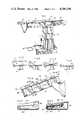
- FIG. 1is a perspective view of a power-operated examination table equipped with a controller embodying this invention.
- FIGS. 2-5illustrate four typical adjustments that such a power-operated table is capable of performing.
- FIG. 6is a perspective view illustrating the controller and its method of operation.
- FIG. 7is an end elevational view taken along line 7--7 of FIG. 6.
- FIG. 8is a transverse vertical sectional view taken along line 8--8 of FIG. 6.
- FIG. 9is an enlarged top plan view of the foot control assembly.
- FIG. 10is a front elevational view taken along line 10--10 of FIG. 9.
- FIG. 11is a top plan view similar to FIG. 9 but with the actuating members removed and top panel cut away to reveal inner components of the assembly.
- the numeral 10generally designates a medical examination table having a power-operated telescoping pedestal 11, a base 12, and a top 13 composed of seat section 13a, back section 13b, foot and leg support section 13c, and headrest section 13d.
- the seat, backrest, and leg support sections 13a-13care all hingedly connected and may be adjusted under power into any of a variety of selected positions.
- the telescoping pedestal 11may be extended or retracted under power, and the seat section 13a may be power-driven into rearwardly and forwardly tipped positions when the table is to be adjusted into a Trendelenburg or reverse Trendelenburg position.
- Such power operationis produced by several electric motors that are concealed within the base and/or top sections and are not visible in the drawings; as well known in the art, other types of power drives, such as hydraulic motors or a combination of electric and hydraulic power systems, might be used.
- the entire structurehas been described as a "table” but it might also be regarded as a chair since it is fully capable of being used as an examination chair when the pedestal is lowered, the backrest fully raised, and the legrest lowered.
- the table/chair 10 depicted in FIGS. 1-5is shown only for purposes of illustration and that the invention disclosed herein might be used in conjunction with other types of power-operated multi-position tables, chairs, and the like.
- the particular examination table shownis a Model 1K2 table, Hamilton Industries, Two Rivers, Wis.
- the foot control assembly 20 depicted in the drawingsis electrically connected to the table and includes a flat, elongated housing 21 having a top wall or panel 22, rear wall 34, front wall 24, end walls 25, and bottom wall 26.
- the illustrated housingis intended to rest upon a floor surface and, to reduce slipping movement on such a surface, the bottom wall or panel may be provided with anti-friction floor pads 26a formed of textured rubber or other suitable material.
- the controller 20is shown as a separate unit connected by an electrical umbilical cord to the table base, it should be understood that the controller may be provided as part of the base, be located slightly above (but in closed proximity to) the floor surface, and may be operatively connected for hydraulic or fluidic actuation rather than electrical actuation of the drive mechanisms.
- a plurality of actuating membersare spaced apart along top wall 22 for lateral contact with the foot of a user.
- five such members 27a-27eare shown, but it is to be understood that a greater or lesser number may be provided (and the width of the housing increased or decreased accordingly) depending on the number of reversible power functions to be performed by the table 10. In the illustration given, there are four such reversible functions requiring a minimum of five actuating members.
- Members 27a-27eare spaced uniformly apart and, in the embodiment illustrated, are normally disposed in parallel relation.
- Four operating stations 28a-28dare provided by the foot control assembly 20 represented in the drawings.
- Such spacingallows the toe portion of an operator's foot to be advanced into an operating station without engaging more than a single actuating member (FIG. 6).
- planar top wall 22has been described as being generally horizontal, ideally it has a slight rearward and upward slope as shown most clearly in FIG. 8.
- a slope of approximately 6 degreesis illustrated and, in general, such slope should fall within the range of 0 to 20 degrees from the horizontal, with an angle within the range of 3 to 10 degrees being preferred.
- the particular angle selectedmay depend partly on the height of the actuating members above a floor surface as measured at the front of the controller. That dimension, which corresponds to the height of front wall 24, is approximately 0.5 inches in the illustrated embodiment and, in any event, should be no greater than about 1.0 inches.
- Such an arrangementpermits a user to operate the foot control assembly with the toe portion of one foot while maintaining full weight upon the heel placed on the floor directly in front of the assembly.
- the heelis utilized as a pivot for foot movement with the toe portion being slid laterally one way or the other over the planar surface 22 at a selected control station to contact one or the other of a pair of actuating members and thereby activate a selected power operation of table 10.
- each actuating member 27a-27eis elongated in a forward-rearward direction with respect to the housing 21 and is generally rectangular in configuration.
- each memberNear its front end, each member is equipped with a second depending pin or threaded stud 30 that extends downwardly through a laterally elongated slot 31 in the top wall 22 (FIG. 9), the stud or pin 30 being equipped at its lower end beneath the top wall with a ring or washer 32 (FIG. 8) to provide an enlarged bearing element.
- U-shaped springs 33are secured to the front wall 24 within the housing and are arranged so that the arms 33a of each spring bear against the enlarged lower end or bearing member 32 to maintain each actuating member in a neutral position.
- Each memberis also shown to be associated with at least one microswitch 34 mounted beneath top wall 22 with the activating arm 34a of the switch having its free end engaging either a spring arm 33a (as shown) or directly engaging bearing member 32. It will be noted that while the acutating members 27a and 27e at the extreme ends of the foot control assembly 20 are each associated with only a single microswitch 34, the remaining members 27b-27d are each associated with a pair of such switches.
- each operating station 28a-28dis bordered along opposite sides by a pair of actuating members, each station is associated with a pair of microswitches 34 that are electrically connected to the table 10 for activating a particular function in either of two reversible directions.
- FIGS. 2-5illustrate four power-driven reversible table operations capable of being controlled at operating stations 28a-28d of foot control assembly 20.
- the raising and lowering operation depicted in FIG. 2is controlled at station 28a by movement of the foot into operative contact with one of the actuating members 27a and 27b. If member 27a is engaged and shifted laterally, the normally-open microswitch 34 associated with that member is closed to complete the circuit that actuates the driving motor for elevating the table. Conversely, if member 27b is engaged, the motor is activated by the closing of another microswitch associated with member 27b.
- the same member 27bwhen contacted and shifted laterally in the opposite direction by toe action in the second operating station 28b, causes the closing of a second microswitch associated with member 27b that activates a motor causing the back section 13b of the table to be raised (FIG. 3).
- the same member 27bis electrically connected to activate two different functions (lowering the table or raising the backrest) depending on whether it is shifted to the right by toe action at operating station 28a or to the left by toe action occurring in operating station 28b.
- FIG. 4depicts the reverse Trendelenburg and Trendelenburg positions that are initiated at station 28c by lateral foot contact with actuating members 27c and 27d, respectively.
- Member 27cis therefore electrically connected either to activate a lowering of backrest 13b (by outward toe action to the right in operating station 28b) or to tilt the entire top 13 into a reverse Trendelenburg position (by outward toe movement to the left in operating station 28c).
- member 27dwhen shifted to the right from station 28c, causes the table top to be power driven into a Trendelenburg position (broken lines in FIG. 4) or, if shifted to the left from station 28d, causes the legrest 13c to be raised into coplanar position with the seat as shown in solid lines in FIG. 5.
- each of the actuating members 27a-27e of the illustrated embodimentrequires a sideways motion for activation, and since accidental activation has been found to arise most frequently when a user accidentally steps on some part of a conventional control assembly and inadvertently depresses one of the pedals, it is believed apparent that the present construction is less subject to unintentional activation and that a protective guard or cage extending over the actuating members, as found in prior constructions, is not required.
- the foot action required to operate the actuating member of the assembly disclosed hereinis a relatively natural and comfortable action as compared to that required for the operation of at least some of the foot pedal arrangements found in the prior art. Since only toe movement is required to operate the members at any given station, a user may operate the controller without redistributing his (her) weight and without changes in body position that might be undesirable during patient examination or surgical procedures.
Landscapes
- Health & Medical Sciences (AREA)
- Engineering & Computer Science (AREA)
- Life Sciences & Earth Sciences (AREA)
- Animal Behavior & Ethology (AREA)
- General Health & Medical Sciences (AREA)
- Public Health (AREA)
- Veterinary Medicine (AREA)
- Biomedical Technology (AREA)
- Physics & Mathematics (AREA)
- General Physics & Mathematics (AREA)
- Automation & Control Theory (AREA)
- Accommodation For Nursing Or Treatment Tables (AREA)
Abstract
Description
Claims (13)
Priority Applications (1)
| Application Number | Priority Date | Filing Date | Title |
|---|---|---|---|
| US06/537,344US4586398A (en) | 1983-09-29 | 1983-09-29 | Foot control assembly for power-operated tables and the like |
Applications Claiming Priority (1)
| Application Number | Priority Date | Filing Date | Title |
|---|---|---|---|
| US06/537,344US4586398A (en) | 1983-09-29 | 1983-09-29 | Foot control assembly for power-operated tables and the like |
Publications (1)
| Publication Number | Publication Date |
|---|---|
| US4586398Atrue US4586398A (en) | 1986-05-06 |
Family
ID=24142262
Family Applications (1)
| Application Number | Title | Priority Date | Filing Date |
|---|---|---|---|
| US06/537,344Expired - LifetimeUS4586398A (en) | 1983-09-29 | 1983-09-29 | Foot control assembly for power-operated tables and the like |
Country Status (1)
| Country | Link |
|---|---|
| US (1) | US4586398A (en) |
Cited By (67)
| Publication number | Priority date | Publication date | Assignee | Title |
|---|---|---|---|---|
| US4956589A (en)* | 1988-12-12 | 1990-09-11 | Cherlo Victor M | Integrated tool control for work station |
| US5300926A (en)* | 1990-05-09 | 1994-04-05 | Siemens Aktiengesellschaft | Medical apparatus, having a single actuating device |
| US5351571A (en)* | 1992-09-11 | 1994-10-04 | Johnson Robert E | Ergonomically symmetric pedal control system |
| US5422521A (en)* | 1993-11-18 | 1995-06-06 | Liebel-Flarsheim Co. | Foot operated control system for a multi-function device |
| US5587634A (en)* | 1994-11-29 | 1996-12-24 | Ara Electronics Corp. | Human body actuated control apparatus and system for commercial sewing machines |
| FR2749503A1 (en)* | 1996-06-10 | 1997-12-12 | Ge Medical Syst Sa | Table for patient support for use with radiology or surgery |
| USD388056S (en)* | 1995-09-29 | 1997-12-23 | Liebel-Flarsheim Company | Actuator for foot-operated control system |
| US5804786A (en)* | 1996-09-25 | 1998-09-08 | Braaten; Ronald J. | Switch operating mechanism |
| US5883615A (en)* | 1995-09-29 | 1999-03-16 | Liebel-Flarsheim Company | Foot-operated control system for a multi-function |
| US6007550A (en)* | 1996-02-20 | 1999-12-28 | Computer Motion, Inc. | Method and apparatus for performing minimally invasive cardiac procedures |
| USD458780S1 (en) | 2001-06-19 | 2002-06-18 | The Brewer Company, Llc | Drawer front face |
| US6436107B1 (en) | 1996-02-20 | 2002-08-20 | Computer Motion, Inc. | Method and apparatus for performing minimally invasive surgical procedures |
| USD461900S1 (en) | 2001-06-19 | 2002-08-20 | The Brewer Company, Llc | Top for a medical examination table |
| USD461899S1 (en) | 2001-06-19 | 2002-08-20 | The Brewer Company, Llc | Medical examination table |
| USD462674S1 (en) | 2001-06-19 | 2002-09-10 | The Brewer Company, Llc | Medical examination table cabinet |
| USD463861S1 (en) | 2001-06-19 | 2002-10-01 | The Brewer Company, Llc | Stirrup for a medical examination table |
| US6463361B1 (en) | 1994-09-22 | 2002-10-08 | Computer Motion, Inc. | Speech interface for an automated endoscopic system |
| US6550084B2 (en) | 2001-06-19 | 2003-04-22 | The Brewer Company, Llc | Medical examination table step |
| US20030191455A1 (en)* | 2001-05-01 | 2003-10-09 | Dan Sanchez | Pivot point arm for a robotic system used to perform a surgical procedure |
| US20030195662A1 (en)* | 2001-09-07 | 2003-10-16 | Yulun Wang | Modularity system for computer assisted surgery |
| US6642836B1 (en) | 1996-08-06 | 2003-11-04 | Computer Motion, Inc. | General purpose distributed operating room control system |
| US6646541B1 (en) | 1996-06-24 | 2003-11-11 | Computer Motion, Inc. | General purpose distributed operating room control system |
| US6699177B1 (en) | 1996-02-20 | 2004-03-02 | Computer Motion, Inc. | Method and apparatus for performing minimally invasive surgical procedures |
| US6714841B1 (en) | 1995-09-15 | 2004-03-30 | Computer Motion, Inc. | Head cursor control interface for an automated endoscope system for optimal positioning |
| US6726699B1 (en) | 2000-08-15 | 2004-04-27 | Computer Motion, Inc. | Instrument guide |
| US20040124964A1 (en)* | 1996-08-06 | 2004-07-01 | Computer Motion, Inc. | General purpose distributed operating room control system |
| US6793653B2 (en) | 2001-12-08 | 2004-09-21 | Computer Motion, Inc. | Multifunctional handle for a medical robotic system |
| USD496462S1 (en) | 2003-09-29 | 2004-09-21 | The Brewer Company, Llc | Medical examination table |
| US6804581B2 (en) | 1992-08-10 | 2004-10-12 | Computer Motion, Inc. | Automated endoscope system for optimal positioning |
| US20040236352A1 (en)* | 1997-09-22 | 2004-11-25 | Yulun Wang | Method and apparatus for performing minimally invasive cardiac procedures |
| US6839612B2 (en) | 2001-12-07 | 2005-01-04 | Institute Surgical, Inc. | Microwrist system for surgical procedures |
| US6852107B2 (en) | 2002-01-16 | 2005-02-08 | Computer Motion, Inc. | Minimally invasive surgical training using robotics and tele-collaboration |
| US20050038416A1 (en)* | 2002-01-16 | 2005-02-17 | Computer Motion, Inc. | Minimally invasive surgical training using robotics and telecollaboration |
| US20050043717A1 (en)* | 1999-10-01 | 2005-02-24 | Computer Motion, Inc. | Heart stabilizer |
| US20050069377A1 (en)* | 2003-09-29 | 2005-03-31 | The Brewer Company, Llc | Stirrup support indexer for a medical examination table |
| US20050067875A1 (en)* | 2003-09-29 | 2005-03-31 | The Brewer Company, Llc | Headrest linkage |
| US20050066861A1 (en)* | 2003-09-29 | 2005-03-31 | The Brewer Company, Llc | Lifting column for a medical examination table |
| US20050102755A1 (en)* | 2003-09-29 | 2005-05-19 | The Brewer Company, Llc | Leg rest and kneeler assembly for a medical examination table |
| US6905491B1 (en) | 1996-02-20 | 2005-06-14 | Intuitive Surgical, Inc. | Apparatus for performing minimally invasive cardiac procedures with a robotic arm that has a passive joint and system which can decouple the robotic arm from the input device |
| USD507905S1 (en) | 2003-09-29 | 2005-08-02 | The Brewer Company, Llc | Lifting column |
| US20050172404A1 (en)* | 2004-02-06 | 2005-08-11 | Midmark Corporation | Foot control |
| US20050242919A1 (en)* | 1996-08-06 | 2005-11-03 | Intuitive Surgical, Inc. | General purpose distributed operating room control system |
| US20060054395A1 (en)* | 2004-08-17 | 2006-03-16 | Horizon Veterinary Services, Inc. | Telescoping motorized lift platform |
| USD517500S1 (en) | 2004-02-06 | 2006-03-21 | Midmark Corporation | Foot control |
| USD519467S1 (en) | 2004-02-06 | 2006-04-25 | Midmark Corporation | Foot control |
| US7074179B2 (en) | 1992-08-10 | 2006-07-11 | Intuitive Surgical Inc | Method and apparatus for performing minimally invasive cardiac procedures |
| US20060178559A1 (en)* | 1998-11-20 | 2006-08-10 | Intuitive Surgical Inc. | Multi-user medical robotic system for collaboration or training in minimally invasive surgical procedures |
| EP1728493A1 (en)* | 2005-05-30 | 2006-12-06 | OKIN Gesellschaft für Antriebstechnik mbH | Safety device for elevation beds |
| USD535544S1 (en) | 2005-07-28 | 2007-01-23 | The Brewer Company, Llc | Grab bar |
| US20070056102A1 (en)* | 2005-09-14 | 2007-03-15 | Midmark Corporation | Medical examination table with pullout step |
| US20070078539A1 (en)* | 2003-11-03 | 2007-04-05 | Erbe Elektromedizin Gmbh | Control device for controlling electromedical appliances |
| USD569520S1 (en) | 2005-07-28 | 2008-05-20 | Debraal Jack A | Medical examination table cabinet |
| US7408439B2 (en) | 1996-06-24 | 2008-08-05 | Intuitive Surgical, Inc. | Method and apparatus for accessing medical data over a network |
| USD574960S1 (en) | 2005-07-28 | 2008-08-12 | Parrish Vanessa B | Medical examination table top |
| USD574959S1 (en) | 2005-07-28 | 2008-08-12 | Debraal Jack A | Medical examination table |
| US20080227073A1 (en)* | 2005-09-29 | 2008-09-18 | Ryan Scott Bardsley | Methods and Apparatus for Autonomous Casualty Simulation |
| US7513000B2 (en) | 2005-07-28 | 2009-04-07 | The Brewer Company, Llc | Medical examination table |
| WO2009114366A3 (en)* | 2008-03-13 | 2010-01-07 | Mallinckrodt Inc. | Foot-activated controller for medical system |
| US8489235B2 (en) | 1998-11-20 | 2013-07-16 | Intuitive Surgical Operations, Inc. | Cooperative minimally invasive telesurgical system |
| US8845681B2 (en) | 1996-11-22 | 2014-09-30 | Intuitive Surgical Operations, Inc. | Rigidly-linked articulating wrist with decoupled motion transmission |
| US8870900B2 (en) | 1999-11-09 | 2014-10-28 | Intuitive Surgical Operations, Inc. | Endoscopic beating-heart stabilizer and vessel occlusion fastener |
| US9038216B2 (en) | 2005-07-28 | 2015-05-26 | The Brewer Company, Llc | Medical examination table |
| US9119654B2 (en) | 1998-11-20 | 2015-09-01 | Intuitive Surgical Operations, Inc. | Stabilizer for robotic beating-heart surgery |
| US9746874B2 (en) | 2013-07-08 | 2017-08-29 | Johnson Technologies Corporation | Ergonomically symmetric pedal control system |
| US20180281055A1 (en)* | 2017-03-29 | 2018-10-04 | The Boeing Company | Titanium-Cobalt Alloy And Associated Thixoforming Method |
| US20190231627A1 (en)* | 2018-02-01 | 2019-08-01 | Medical Technology Industries, Inc. | Programmable examination and procedure tables and chairs |
| CN110613576A (en)* | 2019-09-23 | 2019-12-27 | 宁波科艺医疗器械有限公司 | Two-way translation liftable electric ophthalmic operating table |
Citations (18)
| Publication number | Priority date | Publication date | Assignee | Title |
|---|---|---|---|---|
| US513213A (en)* | 1894-01-23 | Electric-motor controlling device | ||
| US804595A (en)* | 1905-05-25 | 1905-11-14 | Garhart Dental Mfg Company | Electrical controller. |
| US2416410A (en)* | 1943-02-22 | 1947-02-25 | Leah Ree Shampaine | Operating and examining table |
| US2535021A (en)* | 1946-10-22 | 1950-12-19 | Soundscriber Corp | Foot pedal arrangement for controlling phonograph transcriber switches |
| US2707036A (en)* | 1952-08-20 | 1955-04-26 | Hollub Arthur | Safety gas feeding and brake control mechanism |
| US2747056A (en)* | 1953-04-20 | 1956-05-22 | Westinghouse Air Brake Co | Circuit controller |
| US3046071A (en)* | 1958-07-24 | 1962-07-24 | Shampaine | Head-end control surgical operating table |
| US3143803A (en)* | 1962-05-11 | 1964-08-11 | Joseph P Lunn | Dental lounge unit |
| US3302022A (en)* | 1964-03-24 | 1967-01-31 | Liebel Flarsheim Company Divis | Vertically and horizontally adjustable rotatable urological X-ray table |
| US3318596A (en)* | 1964-05-15 | 1967-05-09 | American Sterilizer Co | Surgical table |
| US3466411A (en)* | 1968-04-17 | 1969-09-09 | Martin Brothers Electric Co Th | Foot-operated switch |
| US3486747A (en)* | 1967-09-27 | 1969-12-30 | Samuel Chayes | Combination medical examining and operating table |
| US3499529A (en)* | 1965-10-11 | 1970-03-10 | American Hospital Supply Corp | Physician's examining table |
| US3631242A (en)* | 1969-06-17 | 1971-12-28 | Simmons Co | Fluoroscope top for cardiac bed which is swingable about a vertical axis of the bed |
| US3678519A (en)* | 1970-03-17 | 1972-07-25 | Borg Warner | Hospital bed |
| US3833782A (en)* | 1973-08-15 | 1974-09-03 | Raymond Lee Organization Inc | Foot pedal switch |
| US3874728A (en)* | 1972-10-21 | 1975-04-01 | Siemens Ag | Dental patients chair with a parallelogram supporting arm |
| US4168099A (en)* | 1978-03-27 | 1979-09-18 | Midmark Corporation | Multi-position examination chair |
- 1983
- 1983-09-29USUS06/537,344patent/US4586398A/ennot_activeExpired - Lifetime
Patent Citations (18)
| Publication number | Priority date | Publication date | Assignee | Title |
|---|---|---|---|---|
| US513213A (en)* | 1894-01-23 | Electric-motor controlling device | ||
| US804595A (en)* | 1905-05-25 | 1905-11-14 | Garhart Dental Mfg Company | Electrical controller. |
| US2416410A (en)* | 1943-02-22 | 1947-02-25 | Leah Ree Shampaine | Operating and examining table |
| US2535021A (en)* | 1946-10-22 | 1950-12-19 | Soundscriber Corp | Foot pedal arrangement for controlling phonograph transcriber switches |
| US2707036A (en)* | 1952-08-20 | 1955-04-26 | Hollub Arthur | Safety gas feeding and brake control mechanism |
| US2747056A (en)* | 1953-04-20 | 1956-05-22 | Westinghouse Air Brake Co | Circuit controller |
| US3046071A (en)* | 1958-07-24 | 1962-07-24 | Shampaine | Head-end control surgical operating table |
| US3143803A (en)* | 1962-05-11 | 1964-08-11 | Joseph P Lunn | Dental lounge unit |
| US3302022A (en)* | 1964-03-24 | 1967-01-31 | Liebel Flarsheim Company Divis | Vertically and horizontally adjustable rotatable urological X-ray table |
| US3318596A (en)* | 1964-05-15 | 1967-05-09 | American Sterilizer Co | Surgical table |
| US3499529A (en)* | 1965-10-11 | 1970-03-10 | American Hospital Supply Corp | Physician's examining table |
| US3486747A (en)* | 1967-09-27 | 1969-12-30 | Samuel Chayes | Combination medical examining and operating table |
| US3466411A (en)* | 1968-04-17 | 1969-09-09 | Martin Brothers Electric Co Th | Foot-operated switch |
| US3631242A (en)* | 1969-06-17 | 1971-12-28 | Simmons Co | Fluoroscope top for cardiac bed which is swingable about a vertical axis of the bed |
| US3678519A (en)* | 1970-03-17 | 1972-07-25 | Borg Warner | Hospital bed |
| US3874728A (en)* | 1972-10-21 | 1975-04-01 | Siemens Ag | Dental patients chair with a parallelogram supporting arm |
| US3833782A (en)* | 1973-08-15 | 1974-09-03 | Raymond Lee Organization Inc | Foot pedal switch |
| US4168099A (en)* | 1978-03-27 | 1979-09-18 | Midmark Corporation | Multi-position examination chair |
Cited By (127)
| Publication number | Priority date | Publication date | Assignee | Title |
|---|---|---|---|---|
| US4956589A (en)* | 1988-12-12 | 1990-09-11 | Cherlo Victor M | Integrated tool control for work station |
| US5300926A (en)* | 1990-05-09 | 1994-04-05 | Siemens Aktiengesellschaft | Medical apparatus, having a single actuating device |
| US20050234433A1 (en)* | 1992-08-10 | 2005-10-20 | Intuitive Surgical, Inc. | Apparatus for performing surgical procedures with a passively flexing robotic assembly |
| US6804581B2 (en) | 1992-08-10 | 2004-10-12 | Computer Motion, Inc. | Automated endoscope system for optimal positioning |
| US7074179B2 (en) | 1992-08-10 | 2006-07-11 | Intuitive Surgical Inc | Method and apparatus for performing minimally invasive cardiac procedures |
| US5351571A (en)* | 1992-09-11 | 1994-10-04 | Johnson Robert E | Ergonomically symmetric pedal control system |
| US5422521A (en)* | 1993-11-18 | 1995-06-06 | Liebel-Flarsheim Co. | Foot operated control system for a multi-function device |
| US6965812B2 (en) | 1994-09-22 | 2005-11-15 | Computer Motion, Inc. | Speech interface for an automated endoscopic system |
| US20060220784A1 (en)* | 1994-09-22 | 2006-10-05 | Intuitive Surgical, Inc., A Delaware Corporation | General purpose distributed operating room control system |
| US6463361B1 (en) | 1994-09-22 | 2002-10-08 | Computer Motion, Inc. | Speech interface for an automated endoscopic system |
| US7395249B2 (en) | 1994-09-22 | 2008-07-01 | Intuitive Surgical, Inc. | Speech interface for an automated endoscope system |
| US5587634A (en)* | 1994-11-29 | 1996-12-24 | Ara Electronics Corp. | Human body actuated control apparatus and system for commercial sewing machines |
| US6714841B1 (en) | 1995-09-15 | 2004-03-30 | Computer Motion, Inc. | Head cursor control interface for an automated endoscope system for optimal positioning |
| US5883615A (en)* | 1995-09-29 | 1999-03-16 | Liebel-Flarsheim Company | Foot-operated control system for a multi-function |
| USD388056S (en)* | 1995-09-29 | 1997-12-23 | Liebel-Flarsheim Company | Actuator for foot-operated control system |
| US6905491B1 (en) | 1996-02-20 | 2005-06-14 | Intuitive Surgical, Inc. | Apparatus for performing minimally invasive cardiac procedures with a robotic arm that has a passive joint and system which can decouple the robotic arm from the input device |
| US6699177B1 (en) | 1996-02-20 | 2004-03-02 | Computer Motion, Inc. | Method and apparatus for performing minimally invasive surgical procedures |
| US7695481B2 (en) | 1996-02-20 | 2010-04-13 | Intuitive Surgical, Inc. | Medical robotic system with different scaling factors |
| US7914521B2 (en) | 1996-02-20 | 2011-03-29 | Intuitive Surgical Operations, Inc. | Method and apparatus for performing minimally invasive cardiac procedures |
| US20040186345A1 (en)* | 1996-02-20 | 2004-09-23 | Computer Motion, Inc. | Medical robotic arm that is attached to an operating table |
| US7083571B2 (en) | 1996-02-20 | 2006-08-01 | Intuitive Surgical | Medical robotic arm that is attached to an operating table |
| US20060167441A1 (en)* | 1996-02-20 | 2006-07-27 | Intuitive Surgical Inc. | Method and apparatus for performing minimally invasive cardiac procedures |
| US7118582B1 (en) | 1996-02-20 | 2006-10-10 | Computer Motion, Inc. | Method and apparatus for performing minimally invasive cardiac procedures |
| US6436107B1 (en) | 1996-02-20 | 2002-08-20 | Computer Motion, Inc. | Method and apparatus for performing minimally invasive surgical procedures |
| US7507199B2 (en) | 1996-02-20 | 2009-03-24 | Intuitive Surgical, Inc. | Method and apparatus for performing minimally invasive cardiac procedures |
| US6007550A (en)* | 1996-02-20 | 1999-12-28 | Computer Motion, Inc. | Method and apparatus for performing minimally invasive cardiac procedures |
| US20080228196A1 (en)* | 1996-02-20 | 2008-09-18 | Intuitive Surgical, Inc. | Surgical robotic system for performing minimally invasive surgical procedures |
| FR2749503A1 (en)* | 1996-06-10 | 1997-12-12 | Ge Medical Syst Sa | Table for patient support for use with radiology or surgery |
| US7408439B2 (en) | 1996-06-24 | 2008-08-05 | Intuitive Surgical, Inc. | Method and apparatus for accessing medical data over a network |
| US7543588B2 (en) | 1996-06-24 | 2009-06-09 | Intuitive Surgical, Inc. | Multi-functional surgical control system switching interface |
| US20060241575A1 (en)* | 1996-06-24 | 2006-10-26 | Yulun Wang | Multi-functional surgical control system switching interface |
| US20040172011A1 (en)* | 1996-06-24 | 2004-09-02 | Yulun Wang | Multi-functional surgical control system and switching interface |
| US6646541B1 (en) | 1996-06-24 | 2003-11-11 | Computer Motion, Inc. | General purpose distributed operating room control system |
| US7097640B2 (en) | 1996-06-24 | 2006-08-29 | Intuitive Surgical, Inc. | Multi-functional surgical control system and switching interface |
| US6642836B1 (en) | 1996-08-06 | 2003-11-04 | Computer Motion, Inc. | General purpose distributed operating room control system |
| US20050242919A1 (en)* | 1996-08-06 | 2005-11-03 | Intuitive Surgical, Inc. | General purpose distributed operating room control system |
| US20040124964A1 (en)* | 1996-08-06 | 2004-07-01 | Computer Motion, Inc. | General purpose distributed operating room control system |
| US7053752B2 (en) | 1996-08-06 | 2006-05-30 | Intuitive Surgical | General purpose distributed operating room control system |
| US7259652B2 (en) | 1996-08-06 | 2007-08-21 | Intuitive Surgical, Inc. | General purpose distributed operating room control system |
| US5804786A (en)* | 1996-09-25 | 1998-09-08 | Braaten; Ronald J. | Switch operating mechanism |
| US8845681B2 (en) | 1996-11-22 | 2014-09-30 | Intuitive Surgical Operations, Inc. | Rigidly-linked articulating wrist with decoupled motion transmission |
| US9402619B2 (en) | 1996-11-22 | 2016-08-02 | Intuitive Surgical Operation, Inc. | Rigidly-linked articulating wrist with decoupled motion transmission |
| US20040236352A1 (en)* | 1997-09-22 | 2004-11-25 | Yulun Wang | Method and apparatus for performing minimally invasive cardiac procedures |
| US9119654B2 (en) | 1998-11-20 | 2015-09-01 | Intuitive Surgical Operations, Inc. | Stabilizer for robotic beating-heart surgery |
| US9867671B2 (en) | 1998-11-20 | 2018-01-16 | Intuitive Surgical Operations, Inc. | Multi-user medical robotic system for collaboration or training in minimally invasive surgical procedures |
| US8527094B2 (en) | 1998-11-20 | 2013-09-03 | Intuitive Surgical Operations, Inc. | Multi-user medical robotic system for collaboration or training in minimally invasive surgical procedures |
| US20060178559A1 (en)* | 1998-11-20 | 2006-08-10 | Intuitive Surgical Inc. | Multi-user medical robotic system for collaboration or training in minimally invasive surgical procedures |
| US9271798B2 (en) | 1998-11-20 | 2016-03-01 | Intuitive Surgical Operations, Inc. | Multi-user medical robotic system for collaboration or training in minimally invasive surgical procedures |
| US8914150B2 (en) | 1998-11-20 | 2014-12-16 | Intuitive Surgical Operations, Inc. | Cooperative minimally invasive telesurgical system |
| US9666101B2 (en) | 1998-11-20 | 2017-05-30 | Intuitive Surgical Operations, Inc. | Multi-user medical robotic system for collaboration or training in minimally invasive surgical procedures |
| US8504201B2 (en) | 1998-11-20 | 2013-08-06 | Intuitive Sugrical Operations, Inc. | Cooperative minimally invasive telesurgical system |
| US8489235B2 (en) | 1998-11-20 | 2013-07-16 | Intuitive Surgical Operations, Inc. | Cooperative minimally invasive telesurgical system |
| US8666544B2 (en) | 1998-11-20 | 2014-03-04 | Intuitive Surgical Operations, Inc. | Cooperative minimally invasive telesurgical system |
| US9636186B2 (en) | 1998-11-20 | 2017-05-02 | Intuitive Surgical Operations, Inc. | Multi-user medical robotic system for collaboration or training in minimally invasive surgical procedures |
| US7217240B2 (en) | 1999-10-01 | 2007-05-15 | Intuitive Surgical, Inc. | Heart stabilizer |
| US20050043717A1 (en)* | 1999-10-01 | 2005-02-24 | Computer Motion, Inc. | Heart stabilizer |
| US8870900B2 (en) | 1999-11-09 | 2014-10-28 | Intuitive Surgical Operations, Inc. | Endoscopic beating-heart stabilizer and vessel occlusion fastener |
| US6726699B1 (en) | 2000-08-15 | 2004-04-27 | Computer Motion, Inc. | Instrument guide |
| US8641698B2 (en) | 2001-05-01 | 2014-02-04 | Intuitive Surgical Operations, Inc. | Pivot point arm for robotic system used to perform a surgical procedure |
| US20030191455A1 (en)* | 2001-05-01 | 2003-10-09 | Dan Sanchez | Pivot point arm for a robotic system used to perform a surgical procedure |
| US9011415B2 (en) | 2001-05-01 | 2015-04-21 | Intuitive Surgical Operations, Inc. | Pivot point arm for a robotic system used to perform a surgical procedure |
| USD461900S1 (en) | 2001-06-19 | 2002-08-20 | The Brewer Company, Llc | Top for a medical examination table |
| USD463861S1 (en) | 2001-06-19 | 2002-10-01 | The Brewer Company, Llc | Stirrup for a medical examination table |
| USD461899S1 (en) | 2001-06-19 | 2002-08-20 | The Brewer Company, Llc | Medical examination table |
| USD458780S1 (en) | 2001-06-19 | 2002-06-18 | The Brewer Company, Llc | Drawer front face |
| USD462674S1 (en) | 2001-06-19 | 2002-09-10 | The Brewer Company, Llc | Medical examination table cabinet |
| US6550084B2 (en) | 2001-06-19 | 2003-04-22 | The Brewer Company, Llc | Medical examination table step |
| US20030195662A1 (en)* | 2001-09-07 | 2003-10-16 | Yulun Wang | Modularity system for computer assisted surgery |
| US6892112B2 (en) | 2001-09-07 | 2005-05-10 | Computer Motion, Inc. | Modularity system for computer assisted surgery |
| US6871117B2 (en) | 2001-09-07 | 2005-03-22 | Intuitive Surgical, Inc. | Modularity system for computer assisted surgery |
| US6836703B2 (en) | 2001-09-07 | 2004-12-28 | Computer Motion, Inc. | Modularity system for computer assisted surgery |
| US6799088B2 (en) | 2001-09-07 | 2004-09-28 | Computer Motion, Inc. | Modularity system for computer assisted surgery |
| US6785593B2 (en) | 2001-09-07 | 2004-08-31 | Computer Motion, Inc. | Modularity system for computer assisted surgery |
| US6728599B2 (en) | 2001-09-07 | 2004-04-27 | Computer Motion, Inc. | Modularity system for computer assisted surgery |
| US20030195661A1 (en)* | 2001-09-07 | 2003-10-16 | Yulun Wang | Modularity system for computer assisted surgery |
| US7239940B2 (en) | 2001-09-07 | 2007-07-03 | Intuitive Surgical, Inc | Modularity system for computer assisted surgery |
| US20030195663A1 (en)* | 2001-09-07 | 2003-10-16 | Yulun Wang | Modularity system for computer assisted surgery |
| US6839612B2 (en) | 2001-12-07 | 2005-01-04 | Institute Surgical, Inc. | Microwrist system for surgical procedures |
| US6793653B2 (en) | 2001-12-08 | 2004-09-21 | Computer Motion, Inc. | Multifunctional handle for a medical robotic system |
| US20050043719A1 (en)* | 2001-12-08 | 2005-02-24 | Computer Motion, Inc. | Multifunctional handle for a medical robotic system |
| US8002767B2 (en) | 2001-12-08 | 2011-08-23 | Intuitive Surgical Operations, Inc. | Multifunctional handle for a medical robotic system |
| US8939891B2 (en) | 2001-12-08 | 2015-01-27 | Intuitive Surgical Operations, Inc. | Multifunctional handle for a medical robotic system |
| US7682357B2 (en) | 2002-01-16 | 2010-03-23 | Intuitive Surgical, Inc. | Tele-medicine system that transmits an entire state of a subsystem |
| US9039681B2 (en) | 2002-01-16 | 2015-05-26 | Intuitive Surgical Operations, Inc. | Minimally invasive surgical training using robotics and telecollaboration |
| US20050038416A1 (en)* | 2002-01-16 | 2005-02-17 | Computer Motion, Inc. | Minimally invasive surgical training using robotics and telecollaboration |
| US6852107B2 (en) | 2002-01-16 | 2005-02-08 | Computer Motion, Inc. | Minimally invasive surgical training using robotics and tele-collaboration |
| US7413565B2 (en) | 2002-01-16 | 2008-08-19 | Intuitive Surgical, Inc. | Minimally invasive surgical training using robotics and telecollaboration |
| US6951535B2 (en) | 2002-01-16 | 2005-10-04 | Intuitive Surgical, Inc. | Tele-medicine system that transmits an entire state of a subsystem |
| US9786203B2 (en) | 2002-01-16 | 2017-10-10 | Intuitive Surgical Operations, Inc. | Minimally invasive surgical training using robotics and telecollaboration |
| US20050066861A1 (en)* | 2003-09-29 | 2005-03-31 | The Brewer Company, Llc | Lifting column for a medical examination table |
| US20050067875A1 (en)* | 2003-09-29 | 2005-03-31 | The Brewer Company, Llc | Headrest linkage |
| US20050102755A1 (en)* | 2003-09-29 | 2005-05-19 | The Brewer Company, Llc | Leg rest and kneeler assembly for a medical examination table |
| US7350249B2 (en) | 2003-09-29 | 2008-04-01 | The Brewer Company, Llc | Leg rest and kneeler assembly for a medical examination table |
| US7093313B2 (en) | 2003-09-29 | 2006-08-22 | The Brewer Company, Llc | Headrest linkage |
| USD507905S1 (en) | 2003-09-29 | 2005-08-02 | The Brewer Company, Llc | Lifting column |
| US20050069377A1 (en)* | 2003-09-29 | 2005-03-31 | The Brewer Company, Llc | Stirrup support indexer for a medical examination table |
| US7083355B2 (en) | 2003-09-29 | 2006-08-01 | The Brewer Company, Llc | Stirrup support indexer for a medical examination table |
| USD496462S1 (en) | 2003-09-29 | 2004-09-21 | The Brewer Company, Llc | Medical examination table |
| US7498532B2 (en)* | 2003-11-03 | 2009-03-03 | Erbe Elektromedizin Gmbh | Control device for controlling electromedical appliances |
| US20070078539A1 (en)* | 2003-11-03 | 2007-04-05 | Erbe Elektromedizin Gmbh | Control device for controlling electromedical appliances |
| USD519467S1 (en) | 2004-02-06 | 2006-04-25 | Midmark Corporation | Foot control |
| US20050172404A1 (en)* | 2004-02-06 | 2005-08-11 | Midmark Corporation | Foot control |
| US7058998B2 (en) | 2004-02-06 | 2006-06-13 | Midmark Corporation | Foot control |
| USD517500S1 (en) | 2004-02-06 | 2006-03-21 | Midmark Corporation | Foot control |
| US20060054395A1 (en)* | 2004-08-17 | 2006-03-16 | Horizon Veterinary Services, Inc. | Telescoping motorized lift platform |
| US20070180620A1 (en)* | 2005-05-30 | 2007-08-09 | Okin Gesellschaft Fur Antriebstechnik Mbh | Safety device for lift beds |
| EP1728493A1 (en)* | 2005-05-30 | 2006-12-06 | OKIN Gesellschaft für Antriebstechnik mbH | Safety device for elevation beds |
| US9038216B2 (en) | 2005-07-28 | 2015-05-26 | The Brewer Company, Llc | Medical examination table |
| USD574959S1 (en) | 2005-07-28 | 2008-08-12 | Debraal Jack A | Medical examination table |
| USD569520S1 (en) | 2005-07-28 | 2008-05-20 | Debraal Jack A | Medical examination table cabinet |
| US8096006B2 (en) | 2005-07-28 | 2012-01-17 | The Brewer Company, Llc | Medical examination table |
| US7513000B2 (en) | 2005-07-28 | 2009-04-07 | The Brewer Company, Llc | Medical examination table |
| USD535544S1 (en) | 2005-07-28 | 2007-01-23 | The Brewer Company, Llc | Grab bar |
| US8479329B2 (en) | 2005-07-28 | 2013-07-09 | The Brewer Company, Llc | Medical examination table |
| USD574960S1 (en) | 2005-07-28 | 2008-08-12 | Parrish Vanessa B | Medical examination table top |
| US7845033B2 (en) | 2005-07-28 | 2010-12-07 | The Brewer Company, Llc | Medical examination table |
| US20070056102A1 (en)* | 2005-09-14 | 2007-03-15 | Midmark Corporation | Medical examination table with pullout step |
| US7386899B2 (en) | 2005-09-14 | 2008-06-17 | Midmark Corporation | Medical examination table with pullout step |
| US20080227073A1 (en)* | 2005-09-29 | 2008-09-18 | Ryan Scott Bardsley | Methods and Apparatus for Autonomous Casualty Simulation |
| US20110011708A1 (en)* | 2008-03-13 | 2011-01-20 | Ellafrits David J | Foot-Activated Controller for Medical System |
| WO2009114366A3 (en)* | 2008-03-13 | 2010-01-07 | Mallinckrodt Inc. | Foot-activated controller for medical system |
| US9746874B2 (en) | 2013-07-08 | 2017-08-29 | Johnson Technologies Corporation | Ergonomically symmetric pedal control system |
| US20180281055A1 (en)* | 2017-03-29 | 2018-10-04 | The Boeing Company | Titanium-Cobalt Alloy And Associated Thixoforming Method |
| US20190231627A1 (en)* | 2018-02-01 | 2019-08-01 | Medical Technology Industries, Inc. | Programmable examination and procedure tables and chairs |
| US10632037B2 (en)* | 2018-02-01 | 2020-04-28 | Medical Technology Industries, Inc. | Programmable examination and procedure tables and chairs |
| US10898402B2 (en)* | 2018-02-01 | 2021-01-26 | Medical Technology Industries, Inc. | Programmable examination and procedure tables and chairs |
| CN110613576A (en)* | 2019-09-23 | 2019-12-27 | 宁波科艺医疗器械有限公司 | Two-way translation liftable electric ophthalmic operating table |
Similar Documents
| Publication | Publication Date | Title |
|---|---|---|
| US4586398A (en) | Foot control assembly for power-operated tables and the like | |
| US4516805A (en) | Multi-position examination chair | |
| US7058998B2 (en) | Foot control | |
| US10595637B2 (en) | Medical support apparatus | |
| EP1011591B1 (en) | Patient-support assembly for thermal support apparatus | |
| US5219204A (en) | Recliner and elevator chair | |
| US11907001B2 (en) | Foot pedal apparatus for use with a workstation controlling a robotic surgery system | |
| US3479086A (en) | Chair for physically handicapped persons | |
| TWI235056B (en) | Adjustable bed | |
| US5094508A (en) | Elevator chair | |
| US20070152508A1 (en) | Foot controller | |
| JP2009501588A (en) | Bed assembly | |
| US3608102A (en) | Hospital bed | |
| US20170296416A1 (en) | Adjustable height medical procedure table | |
| EP3423021A2 (en) | Medical chair | |
| US3889998A (en) | Adjustable dental chair | |
| US4109958A (en) | Medical treatment chair | |
| US5782870A (en) | Foot plate control mechanism for chiropractic table | |
| JP3420567B2 (en) | Ophthalmic examination table | |
| GB2205232A (en) | Bed with hinged panel safety feature | |
| JPH0751339A (en) | Massage machine | |
| JP2917250B2 (en) | Back knee interlocking switching mechanism | |
| KR102374221B1 (en) | Patient safety bed with multipurpose dining table | |
| JPH0220257B2 (en) | ||
| JP2002248137A (en) | Examination table system |
Legal Events
| Date | Code | Title | Description |
|---|---|---|---|
| AS | Assignment | Owner name:HAMILTON INDUSTRIES, INC., TWO RIVERS, WI 54241, A Free format text:ASSIGNMENT OF ASSIGNORS INTEREST.;ASSIGNOR:YINDRA, LEONARD J.;REEL/FRAME:004226/0477 Effective date:19830926 | |
| FEPP | Fee payment procedure | Free format text:PAYOR NUMBER ASSIGNED (ORIGINAL EVENT CODE: ASPN); ENTITY STATUS OF PATENT OWNER: LARGE ENTITY | |
| FPAY | Fee payment | Year of fee payment:4 | |
| AS | Assignment | Owner name:MESA INDUSTRIES, INC., A IL CORP., WISCONSIN Free format text:ASSIGNMENT OF ASSIGNORS INTEREST.;ASSIGNOR:HAMILTON INDUSTRIES, INC., AN IL CORP.;REEL/FRAME:005519/0923 Effective date:19901119 Owner name:MESA INDUSTRIES, INC., WISCONSIN Free format text:ASSIGNMENT OF ASSIGNORS INTEREST;ASSIGNOR:HAMILTON INDUSTRIES, INC.;REEL/FRAME:005519/0923 Effective date:19901119 | |
| AS | Assignment | Owner name:MESA INDUSTRIES, INC., 143 S. JACKSON, ELKHORN, WI Free format text:ASSIGNMENT OF ASSIGNORS INTEREST.;ASSIGNOR:HAMILTON INDUSTRIES, INC., A CORP. OF ILLINOIS;REEL/FRAME:005527/0376 Effective date:19901119 Owner name:HAMILTON INDUSTRIES, INC., 1316 18TH STREET, P.O. Free format text:RELEASED BY SECURED PARTY;ASSIGNOR:MESA INDUSTRIES, INC., A CORP. OF ILLINOIS;REEL/FRAME:005527/0379 Effective date:19901119 Owner name:NATIONAL CANADA FINANCE CORP., 225 WEST WASHINGTON Free format text:SECURITY INTEREST;ASSIGNOR:MESA INDUSTRIES, INC., 143 SOUTH JACKSON STREET, ELKORN, MISSOURI 54241 A CORP. OF ILLINOIS;REEL/FRAME:005527/0434 Effective date:19901119 Owner name:MESA INDUSTRIES, INC., WISCONSIN Free format text:ASSIGNMENT OF ASSIGNORS INTEREST;ASSIGNOR:HAMILTON INDUSTRIES, INC.;REEL/FRAME:005527/0376 Effective date:19901119 Owner name:HAMILTON INDUSTRIES, INC., WISCONSIN Free format text:RELEASED BY SECURED PARTY;ASSIGNOR:MESA INDUSTRIES, INC.;REEL/FRAME:005527/0379 Effective date:19901119 Owner name:NATIONAL CANADA FINANCE CORP., ILLINOIS Free format text:SECURITY INTEREST;ASSIGNOR:MESA INDUSTRIES, INC.;REEL/FRAME:005527/0434 Effective date:19901119 | |
| REMI | Maintenance fee reminder mailed | ||
| REMI | Maintenance fee reminder mailed | ||
| FP | Lapsed due to failure to pay maintenance fee | Effective date:19940511 | |
| FEPP | Fee payment procedure | Free format text:PETITION RELATED TO MAINTENANCE FEES FILED (ORIGINAL EVENT CODE: PMFP); ENTITY STATUS OF PATENT OWNER: LARGE ENTITY | |
| FEPP | Fee payment procedure | Free format text:PETITION RELATED TO MAINTENANCE FEES DENIED/DISMISSED (ORIGINAL EVENT CODE: PMFD); ENTITY STATUS OF PATENT OWNER: LARGE ENTITY | |
| FEPP | Fee payment procedure | Free format text:PETITION RELATED TO MAINTENANCE FEES FILED (ORIGINAL EVENT CODE: PMFP); ENTITY STATUS OF PATENT OWNER: LARGE ENTITY | |
| FEPP | Fee payment procedure | Free format text:PETITION RELATED TO MAINTENANCE FEES GRANTED (ORIGINAL EVENT CODE: PMFG); ENTITY STATUS OF PATENT OWNER: LARGE ENTITY | |
| AS | Assignment | Owner name:MESA INDUSTRIES, INC., WISCONSIN Free format text:SECURITY INTEREST;ASSIGNOR:CFB VENTURE FUND I, INC.;REEL/FRAME:007381/0372 Effective date:19931130 Owner name:MDT DIAGNOSTIC COMPANY, CALIFORNIA Free format text:ASSIGNMENT OF ASSIGNORS INTEREST;ASSIGNOR:MESA INDUSTRIES, INC.;REEL/FRAME:007381/0376 Effective date:19931201 Owner name:MESA INDUSTRIES, INC., WISCONSIN Free format text:SECURITY INTEREST;ASSIGNOR:HAMILTON INDUSTRIES, INC. N/K/A MAYLINE COMPANY, INC.;REEL/FRAME:007381/0379 Effective date:19931201 Owner name:MESA INDUSTRIES, INC., WISCONSIN Free format text:SECURITY INTEREST;ASSIGNOR:MORAMERICA CAPITAL CORPORATION;REEL/FRAME:007381/0388 Effective date:19931129 Owner name:MESA INDUSTRIES, INC., WISCONSIN Free format text:SECURITY INTEREST;ASSIGNOR:NATIONAL CANADA FINANCE CORP;REEL/FRAME:007395/0116 Effective date:19931201 | |
| FPAY | Fee payment | Year of fee payment:8 | |
| SULP | Surcharge for late payment | ||
| STCF | Information on status: patent grant | Free format text:PATENTED CASE |