US4585622A - Chemical microreactor having close temperature control - Google Patents
Chemical microreactor having close temperature controlDownload PDFInfo
- Publication number
- US4585622A US4585622AUS06/463,339US46333983AUS4585622AUS 4585622 AUS4585622 AUS 4585622AUS 46333983 AUS46333983 AUS 46333983AUS 4585622 AUS4585622 AUS 4585622A
- Authority
- US
- United States
- Prior art keywords
- container
- core
- sensing
- tube
- tubular
- Prior art date
- Legal status (The legal status is an assumption and is not a legal conclusion. Google has not performed a legal analysis and makes no representation as to the accuracy of the status listed.)
- Expired - Fee Related
Links
- 239000000126substanceSubstances0.000titleclaimsdescription8
- 238000010438heat treatmentMethods0.000claimsabstractdescription19
- 238000001816coolingMethods0.000claimsabstractdescription18
- 239000002826coolantSubstances0.000claimsabstractdescription11
- 238000012545processingMethods0.000abstractdescription6
- 238000006243chemical reactionMethods0.000description7
- 239000003054catalystSubstances0.000description6
- 239000007789gasSubstances0.000description5
- CURLTUGMZLYLDI-UHFFFAOYSA-NCarbon dioxideChemical compoundO=C=OCURLTUGMZLYLDI-UHFFFAOYSA-N0.000description3
- 230000000694effectsEffects0.000description3
- 239000000376reactantSubstances0.000description3
- 238000012360testing methodMethods0.000description3
- 229910002092carbon dioxideInorganic materials0.000description2
- 239000012159carrier gasSubstances0.000description2
- 238000010276constructionMethods0.000description2
- 239000007788liquidSubstances0.000description2
- 238000004519manufacturing processMethods0.000description2
- BASFCYQUMIYNBI-UHFFFAOYSA-NplatinumChemical compound[Pt]BASFCYQUMIYNBI-UHFFFAOYSA-N0.000description2
- 238000013341scale-upMethods0.000description2
- 230000003466anti-cipated effectEffects0.000description1
- 238000000429assemblyMethods0.000description1
- 239000001569carbon dioxideSubstances0.000description1
- 239000000112cooling gasSubstances0.000description1
- 230000008878couplingEffects0.000description1
- 238000010168coupling processMethods0.000description1
- 238000005859coupling reactionMethods0.000description1
- 238000013461designMethods0.000description1
- 238000011161developmentMethods0.000description1
- 238000011835investigationMethods0.000description1
- 238000012544monitoring processMethods0.000description1
- 238000013021overheatingMethods0.000description1
- 229910052697platinumInorganic materials0.000description1
- 230000001681protective effectEffects0.000description1
- 230000001105regulatory effectEffects0.000description1
- 229910001220stainless steelInorganic materials0.000description1
- 239000010935stainless steelSubstances0.000description1
- 238000003466weldingMethods0.000description1
Images

Classifications
- B—PERFORMING OPERATIONS; TRANSPORTING
- B01—PHYSICAL OR CHEMICAL PROCESSES OR APPARATUS IN GENERAL
- B01J—CHEMICAL OR PHYSICAL PROCESSES, e.g. CATALYSIS OR COLLOID CHEMISTRY; THEIR RELEVANT APPARATUS
- B01J19/00—Chemical, physical or physico-chemical processes in general; Their relevant apparatus
- B01J19/0093—Microreactors, e.g. miniaturised or microfabricated reactors
- B—PERFORMING OPERATIONS; TRANSPORTING
- B01—PHYSICAL OR CHEMICAL PROCESSES OR APPARATUS IN GENERAL
- B01J—CHEMICAL OR PHYSICAL PROCESSES, e.g. CATALYSIS OR COLLOID CHEMISTRY; THEIR RELEVANT APPARATUS
- B01J8/00—Chemical or physical processes in general, conducted in the presence of fluids and solid particles; Apparatus for such processes
- B01J8/02—Chemical or physical processes in general, conducted in the presence of fluids and solid particles; Apparatus for such processes with stationary particles, e.g. in fixed beds
- B01J8/06—Chemical or physical processes in general, conducted in the presence of fluids and solid particles; Apparatus for such processes with stationary particles, e.g. in fixed beds in tube reactors; the solid particles being arranged in tubes
- B01J8/067—Heating or cooling the reactor
- G—PHYSICS
- G05—CONTROLLING; REGULATING
- G05D—SYSTEMS FOR CONTROLLING OR REGULATING NON-ELECTRIC VARIABLES
- G05D23/00—Control of temperature
- G05D23/19—Control of temperature characterised by the use of electric means
- G05D23/1919—Control of temperature characterised by the use of electric means characterised by the type of controller
- B—PERFORMING OPERATIONS; TRANSPORTING
- B01—PHYSICAL OR CHEMICAL PROCESSES OR APPARATUS IN GENERAL
- B01J—CHEMICAL OR PHYSICAL PROCESSES, e.g. CATALYSIS OR COLLOID CHEMISTRY; THEIR RELEVANT APPARATUS
- B01J2208/00—Processes carried out in the presence of solid particles; Reactors therefor
- B01J2208/00008—Controlling the process
- B01J2208/00017—Controlling the temperature
- B01J2208/00026—Controlling or regulating the heat exchange system
- B01J2208/00035—Controlling or regulating the heat exchange system involving measured parameters
- B01J2208/00044—Temperature measurement
- B01J2208/00053—Temperature measurement of the heat exchange medium
- B—PERFORMING OPERATIONS; TRANSPORTING
- B01—PHYSICAL OR CHEMICAL PROCESSES OR APPARATUS IN GENERAL
- B01J—CHEMICAL OR PHYSICAL PROCESSES, e.g. CATALYSIS OR COLLOID CHEMISTRY; THEIR RELEVANT APPARATUS
- B01J2208/00—Processes carried out in the presence of solid particles; Reactors therefor
- B01J2208/00008—Controlling the process
- B01J2208/00017—Controlling the temperature
- B01J2208/00026—Controlling or regulating the heat exchange system
- B01J2208/00035—Controlling or regulating the heat exchange system involving measured parameters
- B01J2208/00044—Temperature measurement
- B01J2208/00061—Temperature measurement of the reactants
- B—PERFORMING OPERATIONS; TRANSPORTING
- B01—PHYSICAL OR CHEMICAL PROCESSES OR APPARATUS IN GENERAL
- B01J—CHEMICAL OR PHYSICAL PROCESSES, e.g. CATALYSIS OR COLLOID CHEMISTRY; THEIR RELEVANT APPARATUS
- B01J2208/00—Processes carried out in the presence of solid particles; Reactors therefor
- B01J2208/00008—Controlling the process
- B01J2208/00017—Controlling the temperature
- B01J2208/00106—Controlling the temperature by indirect heat exchange
- B01J2208/00168—Controlling the temperature by indirect heat exchange with heat exchange elements outside the bed of solid particles
- B01J2208/00212—Plates; Jackets; Cylinders
- B01J2208/00221—Plates; Jackets; Cylinders comprising baffles for guiding the flow of the heat exchange medium
- B—PERFORMING OPERATIONS; TRANSPORTING
- B01—PHYSICAL OR CHEMICAL PROCESSES OR APPARATUS IN GENERAL
- B01J—CHEMICAL OR PHYSICAL PROCESSES, e.g. CATALYSIS OR COLLOID CHEMISTRY; THEIR RELEVANT APPARATUS
- B01J2208/00—Processes carried out in the presence of solid particles; Reactors therefor
- B01J2208/00008—Controlling the process
- B01J2208/00017—Controlling the temperature
- B01J2208/00389—Controlling the temperature using electric heating or cooling elements
- B01J2208/00407—Controlling the temperature using electric heating or cooling elements outside the reactor bed
- B—PERFORMING OPERATIONS; TRANSPORTING
- B01—PHYSICAL OR CHEMICAL PROCESSES OR APPARATUS IN GENERAL
- B01J—CHEMICAL OR PHYSICAL PROCESSES, e.g. CATALYSIS OR COLLOID CHEMISTRY; THEIR RELEVANT APPARATUS
- B01J2219/00—Chemical, physical or physico-chemical processes in general; Their relevant apparatus
- B01J2219/00781—Aspects relating to microreactors
- B01J2219/00819—Materials of construction
- B01J2219/00835—Comprising catalytically active material
- B—PERFORMING OPERATIONS; TRANSPORTING
- B01—PHYSICAL OR CHEMICAL PROCESSES OR APPARATUS IN GENERAL
- B01J—CHEMICAL OR PHYSICAL PROCESSES, e.g. CATALYSIS OR COLLOID CHEMISTRY; THEIR RELEVANT APPARATUS
- B01J2219/00—Chemical, physical or physico-chemical processes in general; Their relevant apparatus
- B01J2219/00781—Aspects relating to microreactors
- B01J2219/00873—Heat exchange
- B—PERFORMING OPERATIONS; TRANSPORTING
- B01—PHYSICAL OR CHEMICAL PROCESSES OR APPARATUS IN GENERAL
- B01J—CHEMICAL OR PHYSICAL PROCESSES, e.g. CATALYSIS OR COLLOID CHEMISTRY; THEIR RELEVANT APPARATUS
- B01J2219/00—Chemical, physical or physico-chemical processes in general; Their relevant apparatus
- B01J2219/00781—Aspects relating to microreactors
- B01J2219/0095—Control aspects
- B01J2219/00952—Sensing operations
- B01J2219/00954—Measured properties
- B01J2219/00961—Temperature
Definitions
- This inventionrelates to chemical reacting apparatus and, in particular, to chemical microreactors for operation at tightly-controlled temperatures.
- microreactorsIn chemical laboratories, it is often desired to employ microreactors to produce chemical reactions at predetermined temperatures of small quantities of reactants, sometimes involving catalysts. Small-sized reactions may be desirable for many reasons, e.g., one of the reactants might be a dangerous gas. Also, if only small amounts of the reactants or catalysts are available, it may be desired to test their properties before proceeding with their further development. The behavior of catalysts themselves under varying temperature conditions may be the object of the investigation and microreactors are valuable because they are more easily able to produce desired changes of temperature than larger test units are. Microreactors with their controlled volumes, rates of flow, and temperatures, are more suited to enable scale up of various production processes.
- microreactorshave included a central reactor tube disposed within a relatively massive metallic heat-conductive core for assisting in the production of even heating.
- the reactor tube and corewere inserted in a protective outer heating jacket having a heating element fixed within it. If the heating jacket-coil sub-assembly had a sufficiently large central space, it enabled different-sized reactor tube-core sub-assemblies to be inserted therein.
- Such apparatushad the concomitant disadvantage that larger cores had higher thermal inertia, so that they made it more difficult to control the heat within the reactor tube itself sufficiently quickly. This could present quite a problem when there was a reaction within the reactor tube itself which was of the exothermic type. Sudden and much higher than anticipated temperatures in the reactor tube could destroy catalysts, for example, associated with the reaction.
- a microreactor assemblyin which first and second sensing means are provided for measuring the respective temperatures within the reactor tube and in the region immediately adjacent its outer wall.
- Cooling meansincluding a core of low thermal inertia are provided contiguous with the outer wall and heating means surround the cooling means.
- the heat sensing elementsare adapted to be coupled to data processing units which can activate or inactivate, as the case may be, the heating and cooling means as a function of the sensed temperatures.
- Microreactor apparatushaving a reactor tube, means for heating and cooling the reactor tube and means within and without the reactor tube for sensing temperature changes, the external sensing means being disposed in heat-conductive relation to both the heating and cooling means.
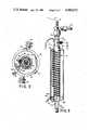
- FIG. 1is a side-elevation view of the complete microreactor assembly
- FIG. 2is a sectional view taken along the section line 2--2 of FIG. 1 in the direction indicated;
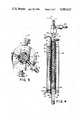
- FIG. 3is a side elevation view, partly in section and partly broken-away, showing more details of the inner construction
- FIG. 4is another side elevation view, partly sectional, which is broken-away differently to show further details of the inner construction.
- FIG. 5is a view taken along the view-lines 5--5 of FIG. 3, partly sectional, in the direction indicated.
- a microreactor assemblyis shown generally at the numeral 10. Beginning from the inside out, there is a reactor tube 14 shown as being metallic, in the middle of which a small metallic tube 12 is axially disposed.
- a thermocouple 11is located in tube 12 and may be moved to any desired position within the tube 12 to permit monitoring the temperature of the reactor tube in any interior region.
- the wire for the thermocoupleis also shown which may be coupled to a central control or data processing unit (not shown).
- a spiral thread or groove 14bis cut in the outer surface 14a, the beginning of the thread being located opposite hole 13c.
- This holecommunicates outwardly with a cooling or cryogenic inlet 19 that is adapted to be coupled to a source (not shown) of liquid CO 2 for example.
- the core 13has its inner surface touching the spirally threaded portion 14b, thereby providing a helical conduit for flow of the coolant down the outside of the tube 14.
- Three transverse holes 13d, spaced at 120°,are drilled in the core enabling the coolant to escape through them.
- a catalystrepresented schematically in the drawings at the numeral 9 whose properties are to be analyzed with relation to different gaseous substances applied to the input of the tube 14, or in relation to different temperatures in it.
- the upper end 14c of the reactor tube 14is adapted to be coupled at inlet 20 to one or more sources of selected gases including carrier gases, for example. These gases then flow through the tube 14 to its lower outlet end 14d to which an appropriate coupling may be attached.
- the tube 14-core 13 sub-assemblyis itself disposed within a slotted metallic tube 15 whose longitudinal slot 15a extends from its upper end to a point close to the lower end of core 13. Fixed along a portion of that slot is a narrow metallic tube 15b. This tube is partially disposed inwardly of the slot so that part comes into contact with the outer surface of core 13.
- a second heat sensor or "RTD" 17is inserted which may comprise, for example, a section of platinum resistance wire whose resistance is a function of temperature. This wire section may itself be incorporated in a bridge circuit of conventional design that produces, when connected to an appropriate electrical source, signals denoting changes in temperature and the direction of those changes. Protruding from the RTD sensor 17 are two leads 17a.
- Wound around the slotted sleeve 15is a heating coil 18 which makes contact with the outer surface of slotted tube 15 as well as a portion of the tube 15b which contains the RTD sensor 17. Coil 18 is also adapted to be connected to a control circuit (not shown) which may be coupled to a central data processing unit.
- the lower end of the sleeve 15is an annular-shaped end cap 15c and the lower portion of tube 14 passes through its central opening with a small clearance. Just above cap 15c two diametrically opposed transverse apertures 15d are formed.
- End cap 16ahas a generally keyhole-shaped aperture to accommodate slotted tube 15. Tapped holes 15d permit end cap 23 to be secured to member 16. End cap 23 has a transverse aperture 23a through which the leads of coil 18 enter via slot 16b. Three screws 21 are screwed into transverse threaded apertures as shown in FIG. 5 until they touch and secure slotted tube 15 in place. Two screws 22 are screwed into respective threaded apertures toward the lower end of housing 16. Screws 22 may be Allen screws.
- Base plate 23has axial passageways formed in it for lead openings.
- thermocouple 11In operation, substances such as gases to be reacted are applied through inlet fitting 20, possibly in an inert carrier gas, and proceed downward into the reactor tube 14 in which a catalyst 9 may be disposed.
- the interior of tube 14has been heated by coil 18 (via tube 15, core 13 and reactor tube 14) to a desired temperature as measured by the thermocouple 11 disposed in axial tube 12.
- RTD sensor 17also measures the temperature of the coil 18. As the heat builds up within the reactor tube 14, the thermocouple 11 transmits corresponding signals to the data processor.
- the processorWhen and if the heat build-up in reactor tube 14, whether solely due to the effects of coil 18 or due to an exothermic reaction, exceeds a predetermined set point, the processor sends signals to appropriate valves that open to permit pulses of a coolant such as liquid carbon dioxide to be applied at the cooling or cryogenic inlet 19. That gas enters into the space between the outer surface 14a of the reactor tube 14 and the inner surface of the core 13. It is guided spirally downward by the threads or grooves 14c formed in surface 14a and exits from core 13 via the three holes 13d into the space between core 13 and slotted tube 15.
- a coolantsuch as liquid carbon dioxide
- the present inventionwith its provision for a first temperature sensing means located right in the reactor tube itself, its low thermal-inertia core, and its external second temperature sensor which makes substantial heat-conductive contact with both the heating and cooling means, overcomes some of the advantages of the prior art.
- the cooling and heating meanscan be effective much more quickly in case of a sudden burst of high temperature due, possibly, to an exothermic reaction within the reactor tube itself. Previous locations of the temperature sensors were such that there would be a large temperature gradient between the heating means and the interior of the reactor tube.
- the present inventionalso effects significant savings in space by the provision of the cooling means as an integral part of, even though external to, the reactor tube.
Landscapes
- Chemical & Material Sciences (AREA)
- Organic Chemistry (AREA)
- Chemical Kinetics & Catalysis (AREA)
- Physics & Mathematics (AREA)
- General Physics & Mathematics (AREA)
- Engineering & Computer Science (AREA)
- Automation & Control Theory (AREA)
- Devices And Processes Conducted In The Presence Of Fluids And Solid Particles (AREA)
- Physical Or Chemical Processes And Apparatus (AREA)
Abstract
Description
Claims (8)
Priority Applications (1)
| Application Number | Priority Date | Filing Date | Title |
|---|---|---|---|
| US06/463,339US4585622A (en) | 1983-02-02 | 1983-02-02 | Chemical microreactor having close temperature control |
Applications Claiming Priority (1)
| Application Number | Priority Date | Filing Date | Title |
|---|---|---|---|
| US06/463,339US4585622A (en) | 1983-02-02 | 1983-02-02 | Chemical microreactor having close temperature control |
Publications (1)
| Publication Number | Publication Date |
|---|---|
| US4585622Atrue US4585622A (en) | 1986-04-29 |
Family
ID=23839761
Family Applications (1)
| Application Number | Title | Priority Date | Filing Date |
|---|---|---|---|
| US06/463,339Expired - Fee RelatedUS4585622A (en) | 1983-02-02 | 1983-02-02 | Chemical microreactor having close temperature control |
Country Status (1)
| Country | Link |
|---|---|
| US (1) | US4585622A (en) |
Cited By (17)
| Publication number | Priority date | Publication date | Assignee | Title |
|---|---|---|---|---|
| US4822570A (en)* | 1986-12-01 | 1989-04-18 | De Dietrich (Usa), Inc. | Thermal sensing apparatus in outlet nozzle |
| US4837374A (en)* | 1987-06-01 | 1989-06-06 | Brown James R | Microreactor for analyzing thin solid samples |
| US4847401A (en)* | 1985-12-31 | 1989-07-11 | Merrell Dow Pharmaceuticals Inc. | Continuous large-scale production of ethyl 2,2-difluoro-4-pentenoate and 2-fluorinated methyl aminoacetonitriles by use of a flow reactor |
| US5084080A (en)* | 1987-11-30 | 1992-01-28 | L'air Liquide, Societe Anonyme Pour L'etude Et L'exploitation Des Procedes Georges Claude | Device for trapping gaseous compounds of refractory metals and pumping plant including same |
| US5100624A (en)* | 1990-06-04 | 1992-03-31 | Fmc Corporation | Apparatus for determining the stability of a peroxygen |
| US5385712A (en)* | 1993-12-07 | 1995-01-31 | Sprunk; Darren K. | Modular chemical reactor |
| US5595707A (en)* | 1990-03-02 | 1997-01-21 | Ventana Medical Systems, Inc. | Automated biological reaction apparatus |
| DE19608297A1 (en)* | 1995-11-29 | 1997-06-05 | Lange Gmbh Dr Bruno | Heated reaction vessel |
| WO2001092225A1 (en)* | 2000-05-29 | 2001-12-06 | Merck Patent Gmbh | Method for producing indols |
| US20030064006A1 (en)* | 2001-10-02 | 2003-04-03 | Carnahan James Claude | Methods and systems for sealed parallel reactions |
| US20050064535A1 (en)* | 2002-12-20 | 2005-03-24 | Dako Cytomation Denmark A/S | Method and apparatus for pretreatment of tissue slides |
| US20060272713A1 (en)* | 2005-05-31 | 2006-12-07 | Garner Sean M | Microfluidic devices with integrated tubular structures |
| US20070149823A1 (en)* | 2004-01-28 | 2007-06-28 | Ube Industries, Ltd., A Corporation Of Japan | Method for producing aldehyde compound or ketone compound by using microreactor |
| DE102006011822A1 (en)* | 2006-03-13 | 2007-09-20 | Technische Universität Darmstadt | Reactor for heterogeneous gas phase reactions, apparatus for testing catalysts for heterogeneous gas phase reactions and methods for testing such catalysts |
| US20090163748A1 (en)* | 2007-12-20 | 2009-06-25 | Man Dwe Gmbh | Tube bundle reactor |
| KR101450363B1 (en)* | 2007-04-11 | 2014-10-14 | 베른트 크리에스매이어 | Device for spraying pigmented fluids |
| CN108499499A (en)* | 2018-04-03 | 2018-09-07 | 同济大学 | A kind of miniature continuous flow-tube reactor of controllable temperature |
Citations (24)
| Publication number | Priority date | Publication date | Assignee | Title |
|---|---|---|---|---|
| US1839738A (en)* | 1928-04-25 | 1932-01-05 | Maria Casale Sacchi | Apparatus for effecting catalytic reactions between gases under pressure and at high temperature |
| US2002525A (en)* | 1933-02-23 | 1935-05-28 | Cambron Adrien | Thermal treatment of gases and vapors |
| US2118567A (en)* | 1935-08-27 | 1938-05-24 | Research Corp | Catalytic oxidation of organic compounds |
| US2222623A (en)* | 1937-03-08 | 1940-11-26 | Houdry Process Corp | Apparatus for controlled treatment of fluids |
| US2408282A (en)* | 1944-07-11 | 1946-09-24 | Wisconsin Alumni Res Found | Fuel distribution system for hightemperature pebble bed furnaces |
| US2508212A (en)* | 1946-12-28 | 1950-05-16 | Owens Illinois Glass Co | Apparatus for heat-treating and sterilizing liquid foods |
| US2622969A (en)* | 1947-12-24 | 1952-12-23 | Universal Oil Prod Co | Recuperative autothermic reactor |
| US2631091A (en)* | 1949-05-21 | 1953-03-10 | Standard Oil Co | High-pressure contacting apparatus |
| US2683652A (en)* | 1951-12-28 | 1954-07-13 | Bell Telephone Labor Inc | Heat treatment of microphonic carbon |
| US2706620A (en)* | 1951-04-28 | 1955-04-19 | Graves Stambaugh Corp | Heat exchanger |
| US2717198A (en)* | 1951-10-25 | 1955-09-06 | Monsanto Chemicals | Ammonia-phosphorus pentoxide reaction products and method of producing same |
| US2887470A (en)* | 1953-12-31 | 1959-05-19 | Snia Viscosa | Process and apparatus for separating and purifying condensations products |
| US3028470A (en)* | 1960-02-12 | 1962-04-03 | Beckman Instruments Inc | Oven temperature control |
| US3057183A (en)* | 1958-08-22 | 1962-10-09 | Phillips Petroleum Co | Chromatographic analyzer |
| US3062624A (en)* | 1959-08-14 | 1962-11-06 | Allegheny Ludlum Steel | Rapid gas analysis |
| US3156734A (en)* | 1961-05-22 | 1964-11-10 | Happel John | Pyrolysis of methane-hydrogen mixtures |
| US3271116A (en)* | 1962-03-06 | 1966-09-06 | Allied Chem | Apparatus for continuous pyrolysis of liquid materials |
| US3279891A (en)* | 1962-07-13 | 1966-10-18 | Siemens Ag | Apparatus for production of fine-crystalline boron phosphide |
| US3414382A (en)* | 1964-12-14 | 1968-12-03 | Standard Oil Co | Method and apparatus for determining the amount of carbon deposited on catalyst |
| US3667914A (en)* | 1970-11-03 | 1972-06-06 | Monsanto Co | Apparatus and process for testing exhaust gas catalyst systems |
| US3787481A (en)* | 1968-04-11 | 1974-01-22 | Snia Viscosa | Method for the continuous performance of esterification under thermal conditions |
| US4234543A (en)* | 1978-10-30 | 1980-11-18 | Thagard Technology Company | Fluid-wall reactor for high temperature chemical reaction processes |
| US4272488A (en)* | 1977-05-25 | 1981-06-09 | John S. Pennish | Apparatus for producing and casting liquid silicon |
| US4474052A (en)* | 1982-12-13 | 1984-10-02 | E. I. Du Pont De Nemours And Company | Laboratory barricade |
- 1983
- 1983-02-02USUS06/463,339patent/US4585622A/ennot_activeExpired - Fee Related
Patent Citations (24)
| Publication number | Priority date | Publication date | Assignee | Title |
|---|---|---|---|---|
| US1839738A (en)* | 1928-04-25 | 1932-01-05 | Maria Casale Sacchi | Apparatus for effecting catalytic reactions between gases under pressure and at high temperature |
| US2002525A (en)* | 1933-02-23 | 1935-05-28 | Cambron Adrien | Thermal treatment of gases and vapors |
| US2118567A (en)* | 1935-08-27 | 1938-05-24 | Research Corp | Catalytic oxidation of organic compounds |
| US2222623A (en)* | 1937-03-08 | 1940-11-26 | Houdry Process Corp | Apparatus for controlled treatment of fluids |
| US2408282A (en)* | 1944-07-11 | 1946-09-24 | Wisconsin Alumni Res Found | Fuel distribution system for hightemperature pebble bed furnaces |
| US2508212A (en)* | 1946-12-28 | 1950-05-16 | Owens Illinois Glass Co | Apparatus for heat-treating and sterilizing liquid foods |
| US2622969A (en)* | 1947-12-24 | 1952-12-23 | Universal Oil Prod Co | Recuperative autothermic reactor |
| US2631091A (en)* | 1949-05-21 | 1953-03-10 | Standard Oil Co | High-pressure contacting apparatus |
| US2706620A (en)* | 1951-04-28 | 1955-04-19 | Graves Stambaugh Corp | Heat exchanger |
| US2717198A (en)* | 1951-10-25 | 1955-09-06 | Monsanto Chemicals | Ammonia-phosphorus pentoxide reaction products and method of producing same |
| US2683652A (en)* | 1951-12-28 | 1954-07-13 | Bell Telephone Labor Inc | Heat treatment of microphonic carbon |
| US2887470A (en)* | 1953-12-31 | 1959-05-19 | Snia Viscosa | Process and apparatus for separating and purifying condensations products |
| US3057183A (en)* | 1958-08-22 | 1962-10-09 | Phillips Petroleum Co | Chromatographic analyzer |
| US3062624A (en)* | 1959-08-14 | 1962-11-06 | Allegheny Ludlum Steel | Rapid gas analysis |
| US3028470A (en)* | 1960-02-12 | 1962-04-03 | Beckman Instruments Inc | Oven temperature control |
| US3156734A (en)* | 1961-05-22 | 1964-11-10 | Happel John | Pyrolysis of methane-hydrogen mixtures |
| US3271116A (en)* | 1962-03-06 | 1966-09-06 | Allied Chem | Apparatus for continuous pyrolysis of liquid materials |
| US3279891A (en)* | 1962-07-13 | 1966-10-18 | Siemens Ag | Apparatus for production of fine-crystalline boron phosphide |
| US3414382A (en)* | 1964-12-14 | 1968-12-03 | Standard Oil Co | Method and apparatus for determining the amount of carbon deposited on catalyst |
| US3787481A (en)* | 1968-04-11 | 1974-01-22 | Snia Viscosa | Method for the continuous performance of esterification under thermal conditions |
| US3667914A (en)* | 1970-11-03 | 1972-06-06 | Monsanto Co | Apparatus and process for testing exhaust gas catalyst systems |
| US4272488A (en)* | 1977-05-25 | 1981-06-09 | John S. Pennish | Apparatus for producing and casting liquid silicon |
| US4234543A (en)* | 1978-10-30 | 1980-11-18 | Thagard Technology Company | Fluid-wall reactor for high temperature chemical reaction processes |
| US4474052A (en)* | 1982-12-13 | 1984-10-02 | E. I. Du Pont De Nemours And Company | Laboratory barricade |
Cited By (53)
| Publication number | Priority date | Publication date | Assignee | Title |
|---|---|---|---|---|
| US4847401A (en)* | 1985-12-31 | 1989-07-11 | Merrell Dow Pharmaceuticals Inc. | Continuous large-scale production of ethyl 2,2-difluoro-4-pentenoate and 2-fluorinated methyl aminoacetonitriles by use of a flow reactor |
| US4822570A (en)* | 1986-12-01 | 1989-04-18 | De Dietrich (Usa), Inc. | Thermal sensing apparatus in outlet nozzle |
| US4837374A (en)* | 1987-06-01 | 1989-06-06 | Brown James R | Microreactor for analyzing thin solid samples |
| US5084080A (en)* | 1987-11-30 | 1992-01-28 | L'air Liquide, Societe Anonyme Pour L'etude Et L'exploitation Des Procedes Georges Claude | Device for trapping gaseous compounds of refractory metals and pumping plant including same |
| US5595707A (en)* | 1990-03-02 | 1997-01-21 | Ventana Medical Systems, Inc. | Automated biological reaction apparatus |
| US7118918B2 (en) | 1990-03-02 | 2006-10-10 | Ventana Medical Systems, Inc. | Automated biological reaction method |
| US6827901B2 (en) | 1990-03-02 | 2004-12-07 | Ventana Medical Systems, Inc. | Automated biological reaction apparatus |
| US6943029B2 (en) | 1990-03-02 | 2005-09-13 | Ventana Medical Systems, Inc. | Automated biological reaction apparatus |
| US5650327A (en)* | 1990-03-02 | 1997-07-22 | Ventana Medical Systems, Inc. | Method for mixing reagent and sample mounted on a slide |
| US5654200A (en)* | 1990-03-02 | 1997-08-05 | Ventana Medical Systems, Inc. | Automated slide processing apparatus with fluid injector |
| US5654199A (en)* | 1990-03-02 | 1997-08-05 | Ventana Medical Systems, Inc. | Method for rinsing a tissue sample mounted on a slide |
| US20050153453A1 (en)* | 1990-03-02 | 2005-07-14 | Ventana Medical Systems, Inc. | Automated biological reaction apparatus |
| US7470541B2 (en) | 1990-03-02 | 2008-12-30 | Ventana Medical System, Inc. | Automated biological reaction apparatus |
| US5100624A (en)* | 1990-06-04 | 1992-03-31 | Fmc Corporation | Apparatus for determining the stability of a peroxygen |
| US5385712A (en)* | 1993-12-07 | 1995-01-31 | Sprunk; Darren K. | Modular chemical reactor |
| DE19608297A1 (en)* | 1995-11-29 | 1997-06-05 | Lange Gmbh Dr Bruno | Heated reaction vessel |
| JP2004501115A (en)* | 2000-05-29 | 2004-01-15 | メルク パテント ゲゼルシャフト ミット ベシュレンクテル ハフトング | Method for producing indole |
| WO2001092225A1 (en)* | 2000-05-29 | 2001-12-06 | Merck Patent Gmbh | Method for producing indols |
| US20030064006A1 (en)* | 2001-10-02 | 2003-04-03 | Carnahan James Claude | Methods and systems for sealed parallel reactions |
| US7400983B2 (en) | 2002-12-20 | 2008-07-15 | Dako Denmark A/S | Information notification sample processing system and methods of biological slide processing |
| US8784735B2 (en) | 2002-12-20 | 2014-07-22 | Dako Denmark A/S | Apparatus for automated processing biological samples |
| US20060088928A1 (en)* | 2002-12-20 | 2006-04-27 | Dakocytomation Denmark A/S | Method and apparatus for automatic staining of tissue samples |
| US10156580B2 (en) | 2002-12-20 | 2018-12-18 | Dako Denmark A/S | Information notification sample processing system and methods of biological slide processing |
| US9778273B2 (en) | 2002-12-20 | 2017-10-03 | Dako Denmark A/S | Isolated communication sample processing system and methods of biological slide processing |
| US9599630B2 (en) | 2002-12-20 | 2017-03-21 | Dako Denmark A/S | Method and apparatus for automatic staining of tissue samples |
| US9229016B2 (en) | 2002-12-20 | 2016-01-05 | Dako Denmark A/S | Information notification sample processing system and methods of biological slide processing |
| US20060085140A1 (en)* | 2002-12-20 | 2006-04-20 | Gordon Feingold | Information notification sample processing system and methods of biological slide processing |
| US20050064535A1 (en)* | 2002-12-20 | 2005-03-24 | Dako Cytomation Denmark A/S | Method and apparatus for pretreatment of tissue slides |
| US8969086B2 (en) | 2002-12-20 | 2015-03-03 | Dako Denmark A/S | Enhanced scheduling sample processing system and methods of biological slide processing |
| US8788217B2 (en) | 2002-12-20 | 2014-07-22 | Dako Denmark A/S | Information notification sample processing system and methods of biological slide processing |
| US7648678B2 (en) | 2002-12-20 | 2010-01-19 | Dako Denmark A/S | Method and system for pretreatment of tissue slides |
| US20060172426A1 (en)* | 2002-12-20 | 2006-08-03 | Dakocytomation Denmark A/S | Systems and methods of sample processing and temperature control |
| US7758809B2 (en) | 2002-12-20 | 2010-07-20 | Dako Cytomation Denmark A/S | Method and system for pretreatment of tissue slides |
| US7937228B2 (en) | 2002-12-20 | 2011-05-03 | Dako Denmark A/S | Information notification sample processing system and methods of biological slide processing |
| US7960178B2 (en) | 2002-12-20 | 2011-06-14 | Dako Denmark A/S | Enhanced scheduling sample processing system and methods of biological slide processing |
| US8216512B2 (en) | 2002-12-20 | 2012-07-10 | Dako Denmark A/S | Apparatus for automated processing biological samples |
| US8257968B2 (en) | 2002-12-20 | 2012-09-04 | Dako Denmark A/S | Method and apparatus for automatic staining of tissue samples |
| US8298815B2 (en) | 2002-12-20 | 2012-10-30 | Dako Denmark A/S | Systems and methods of sample processing and temperature control |
| US8386195B2 (en) | 2002-12-20 | 2013-02-26 | Dako Denmark A/S | Information notification sample processing system and methods of biological slide processing |
| US8394635B2 (en) | 2002-12-20 | 2013-03-12 | Dako Denmark A/S | Enhanced scheduling sample processing system and methods of biological slide processing |
| US8673642B2 (en) | 2002-12-20 | 2014-03-18 | Dako Denmark A/S | Enhanced scheduling sample processing system and methods of biological slide processing |
| US8529836B2 (en) | 2002-12-20 | 2013-09-10 | Dako Denmark A/S | Apparatus for automated processing biological samples |
| US8663978B2 (en) | 2002-12-20 | 2014-03-04 | Dako Denmark A/S | Method and apparatus for automatic staining of tissue samples |
| US7332632B2 (en)* | 2004-01-28 | 2008-02-19 | Ubē Industries, Ltd. | Method for producing aldehyde compound or ketone compound by using microreactor |
| US20070149823A1 (en)* | 2004-01-28 | 2007-06-28 | Ube Industries, Ltd., A Corporation Of Japan | Method for producing aldehyde compound or ketone compound by using microreactor |
| US20060272713A1 (en)* | 2005-05-31 | 2006-12-07 | Garner Sean M | Microfluidic devices with integrated tubular structures |
| DE102006011822B4 (en)* | 2006-03-13 | 2010-05-20 | Technische Universität Darmstadt | Reactor for heterogeneous gas phase reactions, apparatus for testing catalysts for heterogeneous gas phase reactions and methods for testing such catalysts |
| DE102006011822A1 (en)* | 2006-03-13 | 2007-09-20 | Technische Universität Darmstadt | Reactor for heterogeneous gas phase reactions, apparatus for testing catalysts for heterogeneous gas phase reactions and methods for testing such catalysts |
| KR101450363B1 (en)* | 2007-04-11 | 2014-10-14 | 베른트 크리에스매이어 | Device for spraying pigmented fluids |
| US8524156B2 (en) | 2007-12-20 | 2013-09-03 | Man Dwe Gmbh | Tube bundle reactor |
| DE102007061477A1 (en)* | 2007-12-20 | 2009-07-02 | Man Dwe Gmbh | Tube reactor |
| US20090163748A1 (en)* | 2007-12-20 | 2009-06-25 | Man Dwe Gmbh | Tube bundle reactor |
| CN108499499A (en)* | 2018-04-03 | 2018-09-07 | 同济大学 | A kind of miniature continuous flow-tube reactor of controllable temperature |
Similar Documents
| Publication | Publication Date | Title |
|---|---|---|
| US4585622A (en) | Chemical microreactor having close temperature control | |
| EP0074491B1 (en) | Heated junction thermocouple level measurement apparatus | |
| CN101462033B (en) | Tube bundle reactor | |
| US6423948B1 (en) | Microtiter plate with integral heater | |
| US4170455A (en) | Gas monitoring method and apparatus therefor | |
| US4031740A (en) | Apparatus for thermoanalytical investigations | |
| JP3811504B2 (en) | Thermal measurement probe | |
| JPH04262279A (en) | Temperature controlling apparatus for sample | |
| US4361053A (en) | Molten metal bath temperature sensor and sampler | |
| US4440716A (en) | In-situ calibration of local power measuring devices for nuclear reactors | |
| US4532799A (en) | Liquid level sensor | |
| US5163753A (en) | Differential thermal analysis calorimeter for thermal hazard testing | |
| US4404845A (en) | Thermal regulator for liquid chromatographs | |
| Lundin et al. | A simple device to maintain temperatures in the range 4.2–100 K for EPR measurements | |
| US4064756A (en) | Instrument assembly | |
| JP2000185230A (en) | Measurement of parameter in reactor having movable stirrer | |
| EP0616210A1 (en) | Flow cell for calorimetric measurements | |
| GB2129703A (en) | Reactor | |
| US4102196A (en) | Heat sensor | |
| US3505024A (en) | Microcalorimeter flow cell | |
| Flaischlen et al. | Non-invasive temperature measurement in fixed bed reactors using RFID technology | |
| JP6231295B2 (en) | Reactor | |
| US3598534A (en) | Mixing device | |
| US3159996A (en) | Heating apparatus for chromatographic column | |
| AU635257B2 (en) | Indicating device |
Legal Events
| Date | Code | Title | Description |
|---|---|---|---|
| AS | Assignment | Owner name:CHEMICAL DATA SYSTEMS, INC., 7000 LIMESTONE ROAD, Free format text:ASSIGNMENT OF ASSIGNORS INTEREST.;ASSIGNORS:BOWE, WOODFORD A.;LARGIONE, ROBERT;LEVY, EUGENE J.;REEL/FRAME:004091/0496 Effective date:19830128 | |
| AS | Assignment | Owner name:AE/CDS, AUTOCLAVE, INC. Free format text:CHANGE OF NAME;ASSIGNOR:CHEMICAL DATA SYSTEMS, INC.;REEL/FRAME:004507/0993 Effective date:19840802 | |
| FEPP | Fee payment procedure | Free format text:PAYOR NUMBER ASSIGNED (ORIGINAL EVENT CODE: ASPN); ENTITY STATUS OF PATENT OWNER: LARGE ENTITY Free format text:PAT HLDR NO LONGER CLAIMS SMALL ENT STAT AS INDIV INVENTOR (ORIGINAL EVENT CODE: LSM1); ENTITY STATUS OF PATENT OWNER: LARGE ENTITY | |
| FPAY | Fee payment | Year of fee payment:4 | |
| AS | Assignment | Owner name:AE/CDS, AUTOCLAVE, INC., A CORP. OF PA Free format text:CHANGE OF NAME;ASSIGNOR:CHEMICAL DATA SYSTEMS, INC.;REEL/FRAME:005251/0149 Effective date:19840802 Owner name:AUTOCLAVE ENGINEERS, INC., A PA CORP. Free format text:MERGER;ASSIGNOR:AE/CDS, AUTOCLAVE, INC., (MERGED TO);REEL/FRAME:005250/0001 Effective date:19860523 | |
| REMI | Maintenance fee reminder mailed | ||
| REMI | Maintenance fee reminder mailed | ||
| LAPS | Lapse for failure to pay maintenance fees | ||
| FP | Lapsed due to failure to pay maintenance fee | Effective date:19940501 | |
| STCH | Information on status: patent discontinuation | Free format text:PATENT EXPIRED DUE TO NONPAYMENT OF MAINTENANCE FEES UNDER 37 CFR 1.362 |