US4585154A - Fastener driving tool with adjustable three-part magazine canister assembly - Google Patents
Fastener driving tool with adjustable three-part magazine canister assemblyDownload PDFInfo
- Publication number
- US4585154A US4585154AUS06/593,297US59329784AUS4585154AUS 4585154 AUS4585154 AUS 4585154AUS 59329784 AUS59329784 AUS 59329784AUS 4585154 AUS4585154 AUS 4585154A
- Authority
- US
- United States
- Prior art keywords
- package
- ledges
- bottom wall
- improvement
- peripheral wall
- Prior art date
- Legal status (The legal status is an assumption and is not a legal conclusion. Google has not performed a legal analysis and makes no representation as to the accuracy of the status listed.)
- Expired - Lifetime
Links
Images


Classifications
- B—PERFORMING OPERATIONS; TRANSPORTING
- B25—HAND TOOLS; PORTABLE POWER-DRIVEN TOOLS; MANIPULATORS
- B25C—HAND-HELD NAILING OR STAPLING TOOLS; MANUALLY OPERATED PORTABLE STAPLING TOOLS
- B25C1/00—Hand-held nailing tools; Nail feeding devices
- B25C1/001—Nail feeding devices
- B25C1/003—Nail feeding devices for belts of nails
Definitions
- This inventionrelates to fastener driving tools and, more particularly, to improvements in the magazine canister assembly embodied in tools of this type for containing coiled fastener packages of different sizes.
- a typical magazine canister assembly to which the improvements of the present invention relateis disclosed in commonly assigned U.S. Pat. No. 3,330,462 and consists essentially of three sheet metal parts. Two of the parts are hingedly connected together for movement between a closed operative position and an open access position. In the closed operative position, the two hinged parts provide an essentially enclosed cylindrical container.
- the third partconstitutes a movable bottom wall which is mounted for axial adjustment to accommodate different fastener packages, in which the fastener size varies from one package to the other.
- the means for adjusting the axial position of the bottom wallextends between the movable bottom wall part and the bottom wall provided by one of the hinged parts.
- the canister assembly disclosed in the above patenthas proven to be satisfactory in operation.
- One problem which is encountered with this constructionis that the range of adjustment provided is relatively small so that it is not possible for one canister construction to accommodate as many as three or four different size tools.
- One reason for this lack of accommodation of different size toolsis that the overall size of the canister assembly is fixed even though the bottom wall is adjustable to accommodate some variation in the nail size in the fastener packages received therein.
- a canister assemblywhich achieves the advantages of both types of prior art assemblies described above while eliminating the disadvantages thereof and providing the capaiblity of a greater range of adjustment.
- this objectiveis achieved by providing a canister assembly which is constructed essentially of three parts, each of which is preferably molded of plastic material.
- the three partsinclude a mounting part, a packaging supporting part, and a package covering part, all of which are adjustably interrelated with respect to one another so as to contain a selected one of a series of coiled fastener packages in which the fasteners of each coiled package are of incrementally different lengths with respect to the remaining packages of the series.
- the mounting partis suitably fixed to the tool housing, and the package supporting part includes a generally circular fastener point engaging bottom wall and an integral peripheral wall extending in an axial direction from a substantial portion of the exterior periphery of the bottom wall.
- An adjustable mountacts between the exterior periphery of a portion of the peripheral wall and the mounting part for releasably fixedly supporting the package supporting part on the mounting part in a selected one of a plurality of different operative positions depending upon the nail size of the package which is selected.
- the operative positions of the package supporting partare displaced with respect to the mounting part in an axial direction in parallel relation to itself.
- a movable connectionserves to support the package covering part on the mounting part for movement between (1) an operative position overlying the bottom wall of the package supporting part in any of its selected operative positions so as to contain the corresponding selected package in point supported relation on the bottom wall and within the peripheral confinement of the peripheral wall of the package supporting part, and (2) an access position wherein the space overlying the bottom wall is sufficiently open to permit movement of a package into point supported relation to the bottom wall within the peripheral wall of the package supporting part.
- a releasable lockis provided for releasably locking the package covering part in its operative position.
- the adjustable mountcomprises a series of axially spaced concavely arculately extending supporting ledges formed on the mounting part and a plurality of spaced convexly arcuately extending supporting ledges formed on the peripheral wall of the package supporting part.
- the ledgeshave a cross-sectional configuration similar to meshing gear teeth so as to enable the plurality of ledges of the package supporting part to be operable to be selectively intermeshed between any corresponding plurality of ledges among the series of ledges on the mounting part.
- the ledgesare maintained in selected intermeshing relation by abutments adjacent one end of the ledges engaging with cooperating receses and a latch carried by one of the parts adjacent the opposite end of the ledges releasably engaging with a cooperating axially extending latch receiving surface formed on the other part at the adjacent end of the ledges thereof.
- the latchwhich is preferably an overcenter spring press toggle latch
- the package supporting partis made to separate from the other two parts when the canister assembly is subject to unwanted impact forces, as, for example, when the tool is accidentally dropped.
- the function of separationis highly desirable in the larger size fastener packages because the greater weights encountered can cause damage to the parts if the tool is accidentally dropped, as for example, fracture of plastic parts or permanent deformation of metal parts.
- Another object of the present inventionis the provision of a canister assembly of the type described which is effective in operation over a wide range of adjustment, lightweight and simple in construction, and economical to manufacture.
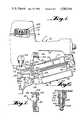
- FIG. 1is a side elevational view with parts broken away for purposes of clearer illustration of a fastener driving tool embodying a canister assembly constructed in accordance with the principles of the present invention.
- FIG. 2is a rear elevational view of the canister assembly showing the rearward connection thereof to the tool housing in-cross section.
- FIG. 3is a top plan view of the canister assembly.
- FIG. 4is a cross-sectional view taken along the line 4--4 of FIG. 3.
- FIG. 5is a sectional view taken along the line 5--5 of FIG. 4.
- FIG. 6is an enlarged fragmentary sectional view taken along the line of 6--6 of FIG. 1 showing the forward connection between the canister assembly and the tool housing.
- FIG. 7is an enlarged fragmentary sectional view taken along the line of 7--7 of FIG. 1 showing the latch mechanism for releasably retaining the canister assembly parts in their closed operative position.
- FIG. 8is a side elevational view of the mounting part of the canister assembly.
- FIG. 9is a rear elevational view of the package supporting part of the canister assembly.
- FIG. 10is a top plan view of the package supporting part shown in FIG. 9.
- the tool 10includes a portable rigid housing assembly, generally indicated at 12, which provides a handle portion 14 and a driving cylinder containing portion 16 extending generally at a right angle at the forward end of the handle portion 14.
- a cylinder 18is mounted within the housing portion 16, within which is slidably mounted a driving piston 20.
- a fastener driving element 22is fixed to the driving piston and extends within a driving track 24 formed in a nose piece 26, forming a part of the housing assembly 12 in a fixed position below the portion 16.
- the handle portion 14contains a reservoir (not shown) for receiving a source of air under pressure which is communicated with the upper end of the cylinder 18 by a pilot pressure operated main valve assembly 28.
- the pilot pressure operated main valve assembly 28is under the control of a trigger valve assembly 30 operated by a trigger assembly 32 in accordance with conventional procedures.
- the nose piece 26includes a ratchet type fastener feeding mechanism, generally indicated at 34, which is operable to cooperate with a leading end portion of a coiled fastener package contained within a canister assembly, generally indicated at 36, which embodies the principles of the present invention.
- the components other than the magazine canister assembly 36are illustrative only and that they may be of any known equivalent construction.
- the components other than the canister assembly 36are exemplarily of the type disclosed in U.S. Pat. No. 3,945,551, the disclosure of which is hereby incorporated by reference into the present specification.
- the coiled fastener packages utilized with the toolmay be of any known construction.
- a preferred embodimentis disclosed in co-pending application Ser. No. 558,533, filed Dec. 6, 1983, the disclosure of which is hereby incorporated by reference into the present specification.
- the fastener package disclosed in the aforesaid co-pending applicationis made up of a series of headed nails interconnected in an array by a pair of parallel wires welded to the shanks of each nail in the array so as to maintain them in substantially parallel relation.
- the fastener feeding mechanism 34includes a swingable door 38 which carries the holding pawl assembly (not shown) of the feeding mechanism.
- the holding pawl assemblyserves to engage the rearward surface of a leading nail of the package so as to prevent rearward movement thereof when the feeding pail assembly (also not shown) is moved through its rearward return stroke after its forward feed stroke has been accomplished.
- the swingable door 38carries a releasable latch mechanism 40 providing a keeper bolt 42 which is adapted to engage within an opening 44 in the tool housing 12 so as to maintain both the fastener feeding mechanism 34 and the canister assembly 36.in their closed operative positions.
- the canister assembly 36is formed essentially of three molded plastic parts including a mounting part, generally indicated at 6, a fastener package supporting part, generally indicated at 48, and a fastener package covering part, generally indicated at 50.
- a mounting partgenerally indicated at 6
- a fastener package supporting partgenerally indicated at 48
- a fastener package covering partgenerally indicated at 50.
- any suitable plastic materialmay be utilized to form the molded parts 46, 48 and 50.
- An exemplary preferred materialis Zytel®, manufactured by DuPont.
- the parts 46 and 48are FE 8018 (14% glass) and the part 50 is ST 801 or ST 800.
- the mounting part 46is essentially in the form of a semi-cylindrical wall 52 having a forward mounting lug 54 extending forwardly from the lower exterior forward edge thereof and a rearward mounting lug 56 extending rearwardly from the upper exterior rearward edge thereof
- the forward extremity of the forward mounting lug 54is laterally offset to engage within a space 58 defined between aligned portions 60 and 62 of the nose piece 26.
- the offset portion of the mounting lug 54is apertured, as at 64, to receive a securing bolt assembly 66 therethrough which also passes through suitable openings in the spaced portions 60 and 62.
- the rearward mounting lug 56is also formed with an opening 68 to receive a mounting bolt assembly 70 which likewise extends through a depending integral portion 72 of the tool housing 12 disposed below the rearward end of the handle portion 14 thereof. It will be understood that the bolt assemblies 66 and 70 serve to fixedly secure the mounting part 46 of the canister assembly 36 with the rigid tool housing 12.
- the main semi-cylindrical wall 52 of the mounting part 46has formed integrally on the interior surface thereof a series of supporting ledges 74 which extend concavely arcuately for an angular extent of approximately 170°.
- the fastener package supporting part 48is formed with a bottom wall 76 of generally circular configuration, having a peripheral wall 78 extending axially from the peripheral edge thereof through a substantial extent thereof, as, for example, approximately 340°.
- a substantial portion of the peripheral wall 78as for example, approximately 180° thereof, has an axial extent greater than the remainder.
- a plurality of convexly arcuately extending supporting ledges 80Formed on the upward axial extension of the peripheral wall 78 on the exterior surface thereof is a plurality of convexly arcuately extending supporting ledges 80.
- the cross-sectional configuration of the ledges 80are complementary with respect to the cross-sectional configuration of the supporting ledges 74 so that the two may be brought together in intermeshing relation somewhat similar to the intermeshing relationship between gear teeth, although, the contact between the ledges is preferably through the entire radial extent thereof rather than along a line.
- the series of supporting ledges 74 on the mounting part 46may exemplarily be twelve whereas the plurality of supporting ledges 80 on the fastener package supporting part 48 is exemplarily three.
- the three ledges 80are capable of intermeshing with the series of twelve ledges 70 in any one of 10 incrementally spaced axial positions.
- the 10 different positionsare provided with indicia of from 1.75 to 4.00 in 0.25 increments which indicia corresponds with the length of shanks included within the fasteners forming the series of coiled fastener packages selected to have their point ends supported on the upwardly facing surface of the bottom wall 76.
- the fastener package supporting part 48is shown with its pluraliy of supporting ledges intermeshed with intermediate ledges 74 within the series provided on the mounting part 46.
- the peripheral wall 52 of the mounting partis formed with a series of recesses or openings 82 at positions between adjacent supporting ledges 74 spaced closely from one of the ends thereof.
- an abutment 84Formed on each of the cooperating supporting ledges 80 is an abutment 84 of a size to enter within the opening or recess 82. It will be noted that the angular position of the abutments 84 enable the same to be readily engaged within the associated openings or recesses 82 prior to the movement of the associated supporting ledges into their full intermeshing relationship.
- the angular position of the abutments 84are such as to prevent disengagement from the recesses 82 in response to a circumferential translational movement of the fastener package supporting part 48 with respect to the mounting part 46 from its full intermeshing position. Consequently, by providing a releasable latch which prevents such movement, the combination of the engagement of the abutments 82 within the recesses 82 and the securement of the latch will serve to fixedly retain the fastener package supporting part 48 in any of its selected positions of adjustment with respect to the mounting part 46. While any suitable latch mechanism may be utilized, as shown, a toggle latch assembly, generally indicated at 86, is preferably carried by the mounting part 46 for cooperative releasable engagement with the fastener package supporting part 48.
- the toggle latch assembly 86includes a first latch member 90 of generally U-shaped cross-sectional configuration, having apertures formed in one end thereof for receiving a pivot pin the ends of which are suitably engaged within the ribs 88.
- Spacer sleeves 94are preferably provided on opposite sides of the pivotal connection of the first latch member 90 with the pivot pin 92.
- the opposite end of the first latch member 90constitutes a manually engageable end 96 and the toggle latch assembly 86 also includes a second latch member 98 which is pivoted, as by a pivot pin 100, at one of its ends to the first latch member 96 intermediate the ends of the latter.
- the opposite end of the second latch member 98is formed into a hooked configuration, as indicated at 102, for cooperative securement with an axially extending latch engaging element 104 formed integrally on the part 48 in radially outwardly extending relation from the exterior surface of the peripheral wall 78 at a position adjacent the ends of the associated plurality of ledges 80.
- the latch engaging element 104is of constant cross section throughout its axial extent and is preferably of hooked shaped configuration to cooperatively receive the hooked shaped end 102 of the second latch member 98.
- the second latch member 98 between its endsis outwardly bowed so as to provide the same with a degree of resilient extension between its ends so that when the latter are extended apart a bias is imposed between the ends tending to move them toward one another. It can thus be seen that the toggle latch assembly 86 operates in generally conventional fashion similar to the toggle latches provided on suitcases or valises.
- the package supporting part 48in addition to the circular bottom wall 76 and the peripheral wall 78, also includes an integral center post 106 which extends axially upwardly from the center of the circular bottom wall 76 for engagement within the open core of the coiled fastener package so as to enable the main body of the coiled fastener package to turn or rotate about the center post as the leading portion is moved outwardly in a generally lateral or tangential direction by the fastener feeding mechanism 34.
- the rearward mounting lug 56 of the mounting part 46extends beyond the mounting aperture 68 and has formed integrally thereon a pair of spaced hinge elements 106.
- the hinge elementsare formed with aligned apertures 108 which have a common axis extending at an angle with respect to a perpendicular plane passing through the axis of the semi-cylindrical wall 52.
- the angular extent of the axisis exemplarily approximately 10°.
- the fastener package covering part 50includes a top wall 110 which is of generally circular configuration of a size to overlay the package supporting part 48 including the bottom wall 76 and the peripheral wall 78 thereof. Extending downwardly from the top wall along a portion of its periphery is a relatively short peripheral wall 112. The peripheral wall has an angular extent of slightly less than 180°. Extending generally tangentially from the rearward end thereof is a hinge element 114 of a size to engage between the hinge elements 106 of the mounting part 46. The hinge element 114 is centrally apertured to receive a pivot pin 115 which also extends through the aligned openings 108 in the hinge elements 106.
- the angular relationship of the pivot pin 116 with respect to a plane passing througn the axis of the central post 106has the effect of enabling the fastener package covering part 50 to move between a closed normal operating position wherein the top wall 110 thereof is disposed in spaced aligned relation with respect to the bottom wall 76 of the fastener package supporting part 48 and an open access wherein the space overlying the bottom wall 76 is sufficiently open to permit movement of a fastener package into point supported relation to the bottom wall within the peripheral wall 76 with the open core fitted over the central post 106.
- the top wall 110 and peripheral wall 112 thereofwill move upwardly and laterally away from the bottom wall 76 and peripheral wall 78 of the package supporting part 48.
- This upward component of movementis important in that it accommodates a flexure or stress of a fastener package holding spring 116.
- the spring 116is preferably formed as an integral portion of the fastener package covering part 50.
- the spring 116is in the form of a generally flat peripherally ribbed rectangular tongue which is integrally connected, as at 118, at one end with the top wall 110.
- the spring 116is molded so as to normally extend downwardly from the hinged connection 118 below the surface of the top wall. Since the part 50 constitutes a single molding, the top wall 110 is formed with a die receiving opening 120 in a position above the spring 116.
- the bottom surface of the springwill move into engagement with the headed end of the fastener package and be resiliently deflected upwardly as the part 50 is moved into its fully closed operative position.
- the spring 116thus serves to normally apply a force on the upper headed end of the fastener package biasing the pointed end into engagement with the upper surface of the bottom wall.
- the portion of the spring 116 which overlies the central post 106 when the part 50 is in its closed positionis formed with an inverted dome-like depression 122, which is adapted to engage within the upper open end of the core of the fastener package so as to cooperate with the central post 106 in guiding the coiled fastener package and rotational movement about its axis as the leading portion is paid out by the operation of the fastener feeding mechanism 34.
- the end of the peripheral wall 112 opposite from the hinge element 114is formed with a downwardly extending locking portion 124.
- This locking portionis disposed in a position to be engaged by a locking portion 126 of the door member 38 when the part 50 is in its closed operative position and the door is likewise disposed in its closed operative position. Release of door latch bolt 42 not only releases the door 38 for movement into its open access position, but the fastener package covering part 50 of the canister assembly 36 as well.
- the canister assembly 36 of the present inventionprovides an effective structure for containing and supporting a coiled fastener package which is not only lightweight but of relatively inexpensive cost.
- the assemblyis made up of essentially three molded plastic parts (46, 48 and 50), two of which (46 and 50) are hinged together for movement between open and closed positions and two of which (48 and 50) are adjustably fixedly interconnected for movement into a plurality of different positions accommodating fastener packages in which the fasteners have a shank size different from the shank size of the fasteners of the other packages in the series.
- the selective adjustmentcan be accomplished relatively simply by disengaging a toggle latch assembly 86 and readjusting the position of the fastener package supporting part 48 with respect to the mounting part 46. After the readjustment, the fixed securement is accomplished by again locking the latch assembly.
- replenishmentcan be easily and conveniently accomplished simply by releasing the latch--42 and enabling the door structure 38 and package covering part 50 of the canister to be swung into their open positions, enabling the new fastener package to be easily fed into operative position after which the parts are moved into their closed position and the latch 40-42 is closed.
- the present canister assemblyachieves both simple and convenient fastener package replacement and overall canister assembly size adjustment commensurate with the adjustment to accommodate the fastener package size. Moreover, these advantages are achieved while at the same time securing a highly desirable wide range of adjustment.
- the wide range of adjustment providedwhich, as previously indicated is from 13/4 to 4 inches, not only permits a wide range of fastener package sizes to be accommodated for a given tool, but, in addition, enables a single canister assembly to accommodate a series of different size tools, as, for example, four different size tools which range in weight and nail size accommodation as follows: (1) a tool weighing 7.6 pounds accommodating nail sizes of from 13/4 to 23/4 inches, (2) an 8 pound tool accommodating nail sizes of from 2 to 31/4 inches, (3) a 10.1 pound tool accommodating nail sizes of from 21/4 to 31/2 inches, and (4) a 10.6 pound tool accommodating nail sizes of from 23/4 to 4 inches.
Landscapes
- Engineering & Computer Science (AREA)
- Mechanical Engineering (AREA)
- Portable Nailing Machines And Staplers (AREA)
- Cookers (AREA)
- Pens And Brushes (AREA)
- Manipulator (AREA)
- Paper (AREA)
- Connection Of Plates (AREA)
- Connection Or Junction Boxes (AREA)
- Surgical Instruments (AREA)
- Sewing Machines And Sewing (AREA)
- Packaging Of Annular Or Rod-Shaped Articles, Wearing Apparel, Cassettes, Or The Like (AREA)
Abstract
Description
Claims (15)
Priority Applications (11)
| Application Number | Priority Date | Filing Date | Title |
|---|---|---|---|
| US06/593,297US4585154A (en) | 1984-03-26 | 1984-03-26 | Fastener driving tool with adjustable three-part magazine canister assembly |
| AU37747/85AAU570162B2 (en) | 1984-03-26 | 1985-01-17 | Pneumatic tool with canister assembly |
| ES540286AES8604803A1 (en) | 1984-03-26 | 1985-02-11 | Fastener driving tool with adjustable three-part canister assembly. |
| AT85301504TATE44486T1 (en) | 1984-03-26 | 1985-03-05 | FASTENER ROLLER WITH ADJUSTABLE THREE-PIECE ROUND MAGAZINE. |
| EP85301504AEP0159126B1 (en) | 1984-03-26 | 1985-03-05 | Fastener driving tool with adjustable three-part canister assembly |
| DE8585301504TDE3571410D1 (en) | 1984-03-26 | 1985-03-05 | Fastener driving tool with adjustable three-part canister assembly |
| JP60049507AJPS60213486A (en) | 1984-03-26 | 1985-03-14 | Fastener driving tool |
| MX204659AMX162934B (en) | 1984-03-26 | 1985-03-19 | IMPROVEMENTS IN A PRESS STRUCTURE FOR PAPER MAKING MACHINE |
| DK125285ADK160681C (en) | 1984-03-26 | 1985-03-20 | SEWING APPLIANCE WITH THIRD-TIME MAGAZINE |
| CA000477355ACA1236951A (en) | 1984-03-26 | 1985-03-25 | Fastener driving tool with adjustable three-part canister assembly |
| MX204725AMX163163B (en) | 1984-03-26 | 1985-03-25 | IMPROVEMENTS TO AN ADJUSTABLE BOX MOUNTING FIXING TOOL FOR THREE-PARTS |
Applications Claiming Priority (1)
| Application Number | Priority Date | Filing Date | Title |
|---|---|---|---|
| US06/593,297US4585154A (en) | 1984-03-26 | 1984-03-26 | Fastener driving tool with adjustable three-part magazine canister assembly |
Publications (1)
| Publication Number | Publication Date |
|---|---|
| US4585154Atrue US4585154A (en) | 1986-04-29 |
Family
ID=24374195
Family Applications (1)
| Application Number | Title | Priority Date | Filing Date |
|---|---|---|---|
| US06/593,297Expired - LifetimeUS4585154A (en) | 1984-03-26 | 1984-03-26 | Fastener driving tool with adjustable three-part magazine canister assembly |
Country Status (10)
| Country | Link |
|---|---|
| US (1) | US4585154A (en) |
| EP (1) | EP0159126B1 (en) |
| JP (1) | JPS60213486A (en) |
| AT (1) | ATE44486T1 (en) |
| AU (1) | AU570162B2 (en) |
| CA (1) | CA1236951A (en) |
| DE (1) | DE3571410D1 (en) |
| DK (1) | DK160681C (en) |
| ES (1) | ES8604803A1 (en) |
| MX (2) | MX162934B (en) |
Cited By (27)
| Publication number | Priority date | Publication date | Assignee | Title |
|---|---|---|---|---|
| US4669648A (en)* | 1983-11-14 | 1987-06-02 | Umberto Monacelli | Magazine for fasteners in coiled form |
| US4858812A (en)* | 1988-06-28 | 1989-08-22 | Stanley-Bostitch, Inc. | Nail driving device with improved nail feeding mechanism |
| USD307234S (en) | 1987-01-20 | 1990-04-17 | Makita Electric Works, Ltd. | Nail gun |
| USD379912S (en)* | 1996-02-28 | 1997-06-17 | Senco Products, Inc. | Pneumatic coil nailer |
| US5697541A (en)* | 1994-12-30 | 1997-12-16 | Senco Products, Inc. | Canister-type magazine for a fastener driving tool |
| US5842625A (en)* | 1994-11-14 | 1998-12-01 | Max Co., Ltd. | Nail guide device of a box nailing machine |
| US5927922A (en)* | 1997-02-10 | 1999-07-27 | High Wind Products, Inc. | Tack, hammer tacker therefor, and method |
| US6032848A (en)* | 1998-11-06 | 2000-03-07 | Illinois Tool Works Inc. | Fastener-driving tool having wear guard defining fastener-guiding surface |
| US6095393A (en)* | 1998-11-06 | 2000-08-01 | Illinois Tool Works Inc. | Fastener-driving tool having magazine mounted to tool handle by mortise and tenon mounting |
| US6126057A (en)* | 1999-02-26 | 2000-10-03 | Li; Ming Chu | Magazine structure for nailing machines |
| US6152346A (en)* | 1999-05-24 | 2000-11-28 | Illinois Tool Work Inc. | Adjustable magazines for nail tools and methods therefor |
| US6189759B1 (en) | 1999-08-06 | 2001-02-20 | Stanley Fastening Systems, Lp | Fastener driving device with enhanced magazine latch assembly |
| US6431428B1 (en)* | 2000-10-16 | 2002-08-13 | Jui-Chin Chen | Pneumatic nail gun |
| US6641019B2 (en)* | 2000-07-28 | 2003-11-04 | Robert Hadfield | Fastener driving tool with multi-size fastener magazine |
| US6644531B2 (en)* | 2000-07-25 | 2003-11-11 | Max Co., Ltd. | Structure and method for fitting magazine to nose member of nailing machine |
| US20040217145A1 (en)* | 2000-12-28 | 2004-11-04 | Naoto Mochizuki | Stapler cartridge and stapler apparatus comprising the same |
| US20040245311A1 (en)* | 2003-05-15 | 2004-12-09 | Mu-Fa Lin | Nail magazine |
| US20050023323A1 (en)* | 2003-07-30 | 2005-02-03 | Jalbert David B. | Integrated check pawl, last nail-retaining, and dry fire lock-out mechanism for fastener-driving tool |
| US20050263560A1 (en)* | 2004-05-25 | 2005-12-01 | Niblett James R | Height adjustable coil nail canister |
| US20060261128A1 (en)* | 2005-05-17 | 2006-11-23 | Ming-Han Wen | Pressing tongue for nails in the magazine for nail gun |
| US20070125824A1 (en)* | 2004-12-03 | 2007-06-07 | Wojcicki Andrzej R | Magazine for wired-collated fasteners with automatic loading |
| US20080110956A1 (en)* | 2005-10-20 | 2008-05-15 | Jeil Tacker Co., Ltd. | Coil nailing device for construction finishing materials |
| US20090114697A1 (en)* | 2004-12-03 | 2009-05-07 | Black & Decker Inc. | Magazine for wired-collated fasteners with automatic loading |
| US20090166393A1 (en)* | 2007-02-01 | 2009-07-02 | Black & Decker Inc. | Multistage solenoid fastening device |
| WO2012006312A1 (en)* | 2010-07-07 | 2012-01-12 | Illinois Tool Works Inc. | Magazine for a nailing tool |
| US8485410B1 (en) | 2008-09-02 | 2013-07-16 | High Wind Products, Inc. | Nail gun magazine for stacked fasteners |
| US12179325B2 (en) | 2022-02-18 | 2024-12-31 | Milwaukee Electric Tool Corporation | Powered fastener driver |
Citations (10)
| Publication number | Priority date | Publication date | Assignee | Title |
|---|---|---|---|---|
| US3259292A (en)* | 1964-03-17 | 1966-07-05 | Bostitch Inc | Fastener driving apparatus |
| US3330462A (en)* | 1966-05-09 | 1967-07-11 | Bostitch Inc | Fastener driving apparatus |
| US3450255A (en)* | 1968-03-08 | 1969-06-17 | Fastener Corp | Bundle or package of fasteners |
| US3543987A (en)* | 1968-06-12 | 1970-12-01 | Fastener Corp | Fastener driving tool |
| US3558031A (en)* | 1966-12-07 | 1971-01-26 | Gaston E Marbaix Ltd | Nail and like magazines |
| US3568908A (en)* | 1968-10-10 | 1971-03-09 | Swingline Inc | Magazine and skip-off preventing mechanism for fluid actuated fastener driving machine |
| US3688966A (en)* | 1969-11-10 | 1972-09-05 | Spotnails | Magazine and feed assembly for a fastener-driving tool |
| US4319705A (en)* | 1979-10-31 | 1982-03-16 | Duo-Fast Corporation | Fastener driving tool |
| JPS5751810A (en)* | 1980-07-23 | 1982-03-26 | Hoechst Ag | High module polyacrylonitrile yarn , fiber and method |
| US4518109A (en)* | 1983-02-02 | 1985-05-21 | Tachikawa Pin Seisakujo Co., Ltd. | Magazine device of air nailer |
Family Cites Families (8)
| Publication number | Priority date | Publication date | Assignee | Title |
|---|---|---|---|---|
| GB1070213A (en)* | 1964-07-08 | 1967-06-01 | George Shey | Refillable cartridge for belt-type staple elements |
| DE2462377C2 (en)* | 1974-08-14 | 1984-05-10 | Max K.K., Tokyo | Magazine container for pneumatic nailers |
| JPS573579B2 (en)* | 1974-11-29 | 1982-01-21 | ||
| IT7622107U1 (en)* | 1976-09-15 | 1978-03-15 | Monacelli Umberto | MAGAZINE FOR BULLETING MACHINE |
| JPS5376206A (en)* | 1976-12-17 | 1978-07-06 | Isuzu Motors Ltd | Exhaust purifying apparatus of internal combustion engine equipment with sub-chamber |
| AU522883B2 (en)* | 1979-04-19 | 1982-07-01 | Signode Corp. | Driving tool |
| JPS56163885A (en)* | 1980-05-22 | 1981-12-16 | Makita Electric Works Ltd | Magazine for nail driver |
| AU1647983A (en)* | 1982-07-28 | 1984-02-02 | Signode Corp. | Magazine for fastener driving tool |
- 1984
- 1984-03-26USUS06/593,297patent/US4585154A/ennot_activeExpired - Lifetime
- 1985
- 1985-01-17AUAU37747/85Apatent/AU570162B2/ennot_activeCeased
- 1985-02-11ESES540286Apatent/ES8604803A1/ennot_activeExpired
- 1985-03-05ATAT85301504Tpatent/ATE44486T1/ennot_activeIP Right Cessation
- 1985-03-05DEDE8585301504Tpatent/DE3571410D1/ennot_activeExpired
- 1985-03-05EPEP85301504Apatent/EP0159126B1/ennot_activeExpired
- 1985-03-14JPJP60049507Apatent/JPS60213486A/enactivePending
- 1985-03-19MXMX204659Apatent/MX162934B/enunknown
- 1985-03-20DKDK125285Apatent/DK160681C/enactive
- 1985-03-25CACA000477355Apatent/CA1236951A/ennot_activeExpired
- 1985-03-25MXMX204725Apatent/MX163163B/enunknown
Patent Citations (11)
| Publication number | Priority date | Publication date | Assignee | Title |
|---|---|---|---|---|
| US3259292A (en)* | 1964-03-17 | 1966-07-05 | Bostitch Inc | Fastener driving apparatus |
| US3330462A (en)* | 1966-05-09 | 1967-07-11 | Bostitch Inc | Fastener driving apparatus |
| US3558031A (en)* | 1966-12-07 | 1971-01-26 | Gaston E Marbaix Ltd | Nail and like magazines |
| US3450255A (en)* | 1968-03-08 | 1969-06-17 | Fastener Corp | Bundle or package of fasteners |
| US3543987A (en)* | 1968-06-12 | 1970-12-01 | Fastener Corp | Fastener driving tool |
| US3568908A (en)* | 1968-10-10 | 1971-03-09 | Swingline Inc | Magazine and skip-off preventing mechanism for fluid actuated fastener driving machine |
| US3688966A (en)* | 1969-11-10 | 1972-09-05 | Spotnails | Magazine and feed assembly for a fastener-driving tool |
| US3945551A (en)* | 1969-11-10 | 1976-03-23 | Max Kabushiki Kaisha | Nailing machine |
| US4319705A (en)* | 1979-10-31 | 1982-03-16 | Duo-Fast Corporation | Fastener driving tool |
| JPS5751810A (en)* | 1980-07-23 | 1982-03-26 | Hoechst Ag | High module polyacrylonitrile yarn , fiber and method |
| US4518109A (en)* | 1983-02-02 | 1985-05-21 | Tachikawa Pin Seisakujo Co., Ltd. | Magazine device of air nailer |
Cited By (38)
| Publication number | Priority date | Publication date | Assignee | Title |
|---|---|---|---|---|
| US4669648A (en)* | 1983-11-14 | 1987-06-02 | Umberto Monacelli | Magazine for fasteners in coiled form |
| USD307234S (en) | 1987-01-20 | 1990-04-17 | Makita Electric Works, Ltd. | Nail gun |
| US4858812A (en)* | 1988-06-28 | 1989-08-22 | Stanley-Bostitch, Inc. | Nail driving device with improved nail feeding mechanism |
| US5842625A (en)* | 1994-11-14 | 1998-12-01 | Max Co., Ltd. | Nail guide device of a box nailing machine |
| US5697541A (en)* | 1994-12-30 | 1997-12-16 | Senco Products, Inc. | Canister-type magazine for a fastener driving tool |
| USD379912S (en)* | 1996-02-28 | 1997-06-17 | Senco Products, Inc. | Pneumatic coil nailer |
| US5927922A (en)* | 1997-02-10 | 1999-07-27 | High Wind Products, Inc. | Tack, hammer tacker therefor, and method |
| US6095393A (en)* | 1998-11-06 | 2000-08-01 | Illinois Tool Works Inc. | Fastener-driving tool having magazine mounted to tool handle by mortise and tenon mounting |
| US6032848A (en)* | 1998-11-06 | 2000-03-07 | Illinois Tool Works Inc. | Fastener-driving tool having wear guard defining fastener-guiding surface |
| US6126057A (en)* | 1999-02-26 | 2000-10-03 | Li; Ming Chu | Magazine structure for nailing machines |
| US6152346A (en)* | 1999-05-24 | 2000-11-28 | Illinois Tool Work Inc. | Adjustable magazines for nail tools and methods therefor |
| US6189759B1 (en) | 1999-08-06 | 2001-02-20 | Stanley Fastening Systems, Lp | Fastener driving device with enhanced magazine latch assembly |
| US6644531B2 (en)* | 2000-07-25 | 2003-11-11 | Max Co., Ltd. | Structure and method for fitting magazine to nose member of nailing machine |
| EP1175969A3 (en)* | 2000-07-25 | 2005-07-20 | Max Co., Ltd. | Structure and method for fitting magazine to nose member of nailing machine |
| US6641019B2 (en)* | 2000-07-28 | 2003-11-04 | Robert Hadfield | Fastener driving tool with multi-size fastener magazine |
| US6431428B1 (en)* | 2000-10-16 | 2002-08-13 | Jui-Chin Chen | Pneumatic nail gun |
| US6913181B2 (en)* | 2000-12-28 | 2005-07-05 | Acco Brands, Inc. | Stapler cartridge and stapler apparatus comprising the same |
| US20040217145A1 (en)* | 2000-12-28 | 2004-11-04 | Naoto Mochizuki | Stapler cartridge and stapler apparatus comprising the same |
| US20040245311A1 (en)* | 2003-05-15 | 2004-12-09 | Mu-Fa Lin | Nail magazine |
| US7048170B2 (en)* | 2003-05-15 | 2006-05-23 | Evening Star International, Inc. | Nail magazine |
| US20050023323A1 (en)* | 2003-07-30 | 2005-02-03 | Jalbert David B. | Integrated check pawl, last nail-retaining, and dry fire lock-out mechanism for fastener-driving tool |
| US6966476B2 (en) | 2003-07-30 | 2005-11-22 | Stanley Fastening Systems, L.P. | Integrated check pawl, last nail-retaining, and dry fire lock-out mechanism for fastener-driving tool |
| US20050263560A1 (en)* | 2004-05-25 | 2005-12-01 | Niblett James R | Height adjustable coil nail canister |
| TWI386288B (en)* | 2004-05-25 | 2013-02-21 | Black & Decker Inc | Height adjustable coil nail canister |
| US8172118B2 (en) | 2004-05-25 | 2012-05-08 | Black & Decker Inc. | Height adjustable coil nail canister |
| US20090114697A1 (en)* | 2004-12-03 | 2009-05-07 | Black & Decker Inc. | Magazine for wired-collated fasteners with automatic loading |
| US7455207B2 (en)* | 2004-12-03 | 2008-11-25 | Black & Decker Inc. | Magazine for wired-collated fasteners with automatic loading |
| US7866521B2 (en) | 2004-12-03 | 2011-01-11 | Black & Decker Inc. | Magazine for wired-collated fasteners with automatic loading |
| US20070125824A1 (en)* | 2004-12-03 | 2007-06-07 | Wojcicki Andrzej R | Magazine for wired-collated fasteners with automatic loading |
| US20060261128A1 (en)* | 2005-05-17 | 2006-11-23 | Ming-Han Wen | Pressing tongue for nails in the magazine for nail gun |
| US20080110956A1 (en)* | 2005-10-20 | 2008-05-15 | Jeil Tacker Co., Ltd. | Coil nailing device for construction finishing materials |
| US7654430B2 (en)* | 2005-10-20 | 2010-02-02 | JEIL TACKER Co. Ltd. | Coil nailing device for construction finishing materials |
| US20090166393A1 (en)* | 2007-02-01 | 2009-07-02 | Black & Decker Inc. | Multistage solenoid fastening device |
| US7665540B2 (en) | 2007-02-01 | 2010-02-23 | Black & Decker Inc. | Multistage solenoid fastening device |
| US7913890B2 (en) | 2007-02-01 | 2011-03-29 | Black & Decker Inc. | Multistage solenoid fastening device |
| US8485410B1 (en) | 2008-09-02 | 2013-07-16 | High Wind Products, Inc. | Nail gun magazine for stacked fasteners |
| WO2012006312A1 (en)* | 2010-07-07 | 2012-01-12 | Illinois Tool Works Inc. | Magazine for a nailing tool |
| US12179325B2 (en) | 2022-02-18 | 2024-12-31 | Milwaukee Electric Tool Corporation | Powered fastener driver |
Also Published As
| Publication number | Publication date |
|---|---|
| AU570162B2 (en) | 1988-03-03 |
| EP0159126A1 (en) | 1985-10-23 |
| AU3774785A (en) | 1985-10-03 |
| ATE44486T1 (en) | 1989-07-15 |
| ES8604803A1 (en) | 1986-03-01 |
| MX162934B (en) | 1991-07-15 |
| CA1236951A (en) | 1988-05-24 |
| DK125285D0 (en) | 1985-03-20 |
| DE3571410D1 (en) | 1989-08-17 |
| DK125285A (en) | 1985-09-27 |
| DK160681C (en) | 1991-09-23 |
| DK160681B (en) | 1991-04-08 |
| MX163163B (en) | 1991-09-25 |
| JPS60213486A (en) | 1985-10-25 |
| ES540286A0 (en) | 1986-03-01 |
| EP0159126B1 (en) | 1989-07-12 |
Similar Documents
| Publication | Publication Date | Title |
|---|---|---|
| US4585154A (en) | Fastener driving tool with adjustable three-part magazine canister assembly | |
| EP0830239B1 (en) | Fastener length adjustable canister-type magazine for a fastener driving tool | |
| US5001817A (en) | Securing and adjustment device particularly for ski boots | |
| US4053094A (en) | Cartridge containing continuous wire coil and portable device for cutting successive lengths from the wire and driving the same | |
| US7377050B2 (en) | Tape measure | |
| EP0955425B1 (en) | Roofing machine | |
| EP0637487B1 (en) | Cartridge for electric stapler | |
| US20100319138A1 (en) | Portable tool kit with auto-release clasp and expandable tools | |
| US4506819A (en) | Staple supply indicator | |
| GB2124962A (en) | Spring actuated fastener driving device | |
| US4716813A (en) | Pneumatically operated stapler with improved actuating and clinching mechanism | |
| US20020162229A1 (en) | Utility knife | |
| CA1175201A (en) | Magazine assembly for coil nails | |
| US4113164A (en) | Stapler | |
| CA2121717A1 (en) | Fastener driving device particularly suited for use as a roofing nailer | |
| WO1999000222A1 (en) | Continuous screw fastening machine | |
| GB1565566A (en) | Devices for rotating screw caps on containers | |
| EP0093605A2 (en) | Emergency locking reels for belts | |
| US4671444A (en) | Stapler with improved jam clearing mechanism | |
| JP2000033305A (en) | Liquid pour-out gun | |
| JPS5914141Y2 (en) | Magazine for clasp driving machine | |
| JPS6128699Y2 (en) | ||
| JPS6233689Y2 (en) | ||
| JPS6237658Y2 (en) | ||
| JPS6212550Y2 (en) |
Legal Events
| Date | Code | Title | Description |
|---|---|---|---|
| AS | Assignment | Owner name:TEXTRON INC., PROVIDENCE, RI A CORP OF DE Free format text:ASSIGNMENT OF ASSIGNORS INTEREST.;ASSIGNORS:FEALEY, WILLIAM S.;CANLAS, PRUDENCIO S.;REEL/FRAME:004245/0155 Effective date:19840321 | |
| STCF | Information on status: patent grant | Free format text:PATENTED CASE | |
| AS | Assignment | Owner name:STANLEY-BOSTITCH, INC., EAST GREENWICH, RHODE ISLA Free format text:ASSIGNMENT OF ASSIGNORS INTEREST.;ASSIGNOR:TEXTRON INC.;REEL/FRAME:004765/0628 Effective date:19870401 Owner name:STANLEY-BOSTITCH, INC., A CORP. OF DE,RHODE ISLAND Free format text:ASSIGNMENT OF ASSIGNORS INTEREST;ASSIGNOR:TEXTRON INC.;REEL/FRAME:004765/0628 Effective date:19870401 | |
| FEPP | Fee payment procedure | Free format text:PAYOR NUMBER ASSIGNED (ORIGINAL EVENT CODE: ASPN); ENTITY STATUS OF PATENT OWNER: LARGE ENTITY | |
| FPAY | Fee payment | Year of fee payment:4 | |
| FPAY | Fee payment | Year of fee payment:8 | |
| FPAY | Fee payment | Year of fee payment:12 | |
| AS | Assignment | Owner name:STANLEY FASTENING SYSTEMS, L.P., RHODE ISLAND Free format text:ASSIGNMENT OF ASSIGNORS INTEREST;ASSIGNOR:STANLEY-BOSTITCH, INC.;REEL/FRAME:009731/0902 Effective date:19990127 |