US4583648A - Angularly adjustable shelf and support - Google Patents
Angularly adjustable shelf and supportDownload PDFInfo
- Publication number
- US4583648A US4583648AUS06/294,638US29463881AUS4583648AUS 4583648 AUS4583648 AUS 4583648AUS 29463881 AUS29463881 AUS 29463881AUS 4583648 AUS4583648 AUS 4583648A
- Authority
- US
- United States
- Prior art keywords
- support
- shelf
- bracket
- notches
- projections
- Prior art date
- Legal status (The legal status is an assumption and is not a legal conclusion. Google has not performed a legal analysis and makes no representation as to the accuracy of the status listed.)
- Expired - Lifetime
Links
Images


Classifications
- A—HUMAN NECESSITIES
- A47—FURNITURE; DOMESTIC ARTICLES OR APPLIANCES; COFFEE MILLS; SPICE MILLS; SUCTION CLEANERS IN GENERAL
- A47B—TABLES; DESKS; OFFICE FURNITURE; CABINETS; DRAWERS; GENERAL DETAILS OF FURNITURE
- A47B55/00—Cabinets, racks or shelf units, having essential features of rigid construction
- A47B55/02—Cabinets, racks or shelf units, having essential features of rigid construction made of wire
- A—HUMAN NECESSITIES
- A47—FURNITURE; DOMESTIC ARTICLES OR APPLIANCES; COFFEE MILLS; SPICE MILLS; SUCTION CLEANERS IN GENERAL
- A47B—TABLES; DESKS; OFFICE FURNITURE; CABINETS; DRAWERS; GENERAL DETAILS OF FURNITURE
- A47B57/00—Cabinets, racks or shelf units, characterised by features for adjusting shelves or partitions
- A47B57/04—Cabinets, racks or shelf units, characterised by features for adjusting shelves or partitions with means for adjusting the inclination of the shelves
- A47B57/045—Cantilever shelves
Definitions
- the present inventionrelates, in general, to shelving, and, more particularly, to adjustable shelving.
- the shelf means embodying the teachings of the present inventionhas means for adjusting the position of that shelf in a plane which is parallel to the supporting surface as well as means for adjusting the angular orientation of that shelf with respect to that supporting surface.
- the angular adjustment featurepermits the shelf means to adapt to a wide variety of situations.
- the shelf support arm of the present inventionacts as an end gate to prevent items stored on the shelf from sliding off the shelf; however, the arm still permits viewing of these items.
- the shelf and arms of the present inventionare collapsible and thus are easily nested together for shipping and/or storing.
- the shelf armcan be attached to a shelf to suppport that shelf from above, thereby adding versatility to the device.
- the shelf armis releasably attachable to a shelf body so that shelf bodies and arms can be interchanged, thereby adding still more versatility to the device.
- FIG. 1is a perspective of a shelf means embodying the teachings of the present invention.
- FIGS. 2-4are elevation views showing various angular orientations of the shelf means embodying the teachings of the present invention with respect to a channel bracket supporting such shelf on a wall or the like.
- FIG. 5is a view taken along line 5--5 of FIG. 4.
- FIG. 6is a view taken along line 6--6 of FIG. 5.
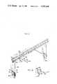
- FIG. 7is a perspective of an alternative embodiment of the shelf means embodying the teachings of the present invention.
- FIGS. 8-10are elevation views showing various angular orientations of the FIG. 7 shelf means with respect to a channel bracket supporting such a shelf means on a wall or the like.
- FIG. 11is a perspective of an alternative embodiment of the present invention.
- FIG. 12is a view taken along line 12--12 of FIG. 11.
- FIG. 13is a perspective of an alternative embodiment of the present invention.
- FIG. 14is a perspective of an alternative embodiment of the present invention.
- FIG. 15is a perspective of an alternative embodiment of the present invention.
- FIGS. 1-6Shown in FIGS. 1-6 is an angularly adjustable shelf means 10 embodying the teachings of the present invention.
- the shelf meansis disengageably mounted on a channel bracket 12 which has oblong holes 14 defined longitudinally therein.
- the channel bracketis a wall standard commonly used to support shelving, and the like, and is attached to a wall or other such supporting structure by fasteners, or the like, as suitable.
- the shelf means 10is symmetric, and thus only one end thereof will be shown and described herein, it being understood that the other end is identical to the end shown and described herein.
- the shelf means 10includes a stepped body 20 having a plurality of levels 22 separated by a riser section 24 and bonded by distal end 26 and proximal end 28.
- the shelf bodypreferably includes a multiplicity of rods 30 and cross-rods 32.
- the rodsare interconnected in groups, as shown by the reference indicator 36 in the preferred embodiment. While rods are disclosed herein, any other forms of the body, such as sheet metal, baskets, prong bars, pocket assemblies, or the like, and ungrouped rods can be used without departing from the scope of the present disclosure.
- Shelf body support arms 40are located on each end of the body.
- the armsare made of wire and sheet metal combined, and each support arm includes a U-shaped body 42 with a support plate 44 on the proximal end thereof.
- the body 42includes leg forming rods 46 and 48 and bight section 50.
- Leg 46includes an offset 52 to make that leg flexible enough to fit a wide variety of items.
- the support armsare coupled to the body 20 by fastener members 56, each of which includes flats 58, 60 and 62 on leg 46 of the arm and are coupled to the outermost rod 30'. Clamps 68 and 70 couple the flats 58 and 62 to the flats 64 and 66 on the arm 30'.
- a plurality of flatsare defined on the support arm so that various shelves and/or shelf positions can be defined by coupling the shelf body to appropriate flats on the support arm, and so that the body 20 can be replaced by an alternative form of the body, which will be discussed below.
- the fastener members 56are included in an overall angular adjustment means for the shelf means 10.
- the support plate 44includes a planar body 72 having a pair of arms 74 and 76 extending outwardly therefrom.
- the arms 74 and 76are spaced apart from each other a distance corresponding to the spacing between the holes 14 on the wall standard 12 so that these arms can be accommodated in the holes 14 as shown in the figures.
- the shelf angular adjustment meansfurther includes a plurality of notches defined in corresponding edges of the plate arms 74 and 76.
- notches 80 and 82are defined in side edge 84 of the arm 74 and notches 86 and 88 are defined in side edge 90 of the leg 76.
- the notchesall open in a common direction as indicated in the figures so that these notches can engage selected edges of the hole defining periphery of the channel bracket.
- notches 80 and 86are aligned so that notches 80 and 86 are in alignment with each other, as are notches 82 and 88. Of course, notches 80 and 88 and 82 and 86 are not in alignment with each other.
- the arms 74 and 76are received in selected holes 14 so that one notch from each arm is engaged against peripheral edge 94 defining each of the holes 14.
- the support plate 44, and hence the shelf,is thus coupled to a wall, or other such member, via the channel bracket.
- the angle of the shelf support arm 40 with respect to the channel bracket 12, and hence with respect to a wallis represented by the indicator B, and is variable by varying the notches used to engage the peripheral edges 94 of the holes 14. It is also noted that the body 20 has an initial angle with respect to the arm 40. In the preferred embodiment, the angle B equals 2° (notches 82 and 86 engaged in holes 14 in FIG. 2, 14° in FIG. 3 (notches 80 and 86 engaged in holes 14), and 28° in FIG. 4 (notches 80 and 88 engaged in holes 14).
- the 2° upward tiltis defined by the angular supporting position of the shelf body 20 with respect to the shelf support arm 40 so that the shelf body assumes the 2° tilt while the plate 44 is extending outwardly at an angle with respect to the wall bracket 12 as shown in FIG. 2.
- shelf means 10includes shelf body 20'.
- the body 20'is planar between the proximal end 28' and the distal end 26', and is coupled to the shelf support arms 40 by fastener members 56 in an angular manner similar to the manner in which body 20 is coupled to the support arms 40 in shelf means 10 to define a pre-mounting tilt of about 2° with respect to the bracket 44.
- the shelf bodies 20 and 20'are interchangeable. It is noted that the flats 60 and 62 on the arm 40 are used to couple the body 20' to that arm.
- a plastic snaplock Pcan also be used to attach the shelf body to the support arm in any embodiment of the present invention.
- the angular orientation of the shelf means 10'is indicated in FIGS. 8-10 and assumes an angle B' with respect to the channel bracket, and hence with respect to the wall, or other such mounting element.
- Angle B'equals 2° in FIG. 9, 14° in FIG. 8 and 28° in FIG. 10.
- the angle B'can be adjusted so that the shelf 20' assumes any suitable orientation such as, for example, horizontal, 2° downwardly, 4° downwardly, or the like.
- the arms 40can also be folded outwardly or inwardly of the shelf so the entire assembly is essentially planar for storage, shipping or the like. Furthermore, the arms can be removed for storage, shipping, or the like.
- FIGS. 11 and 12A further alternative embodiment of the present invention is shown in FIGS. 11 and 12 and includes a support plate 44 having a bar 180 attached thereto, as by welding or the like, to extend upwardly with respect to a mounted plate 44.
- Outer end 182 of the bar 180is attached, as by welding, or the like, to a bracket 186 having holes 188 defined therein to be spaced apart longitudinally of that bracket.
- Prong supports 190are releasably attached to the bracket via the holes 188 to extend outwardly of the bracket as shown in FIGS. 11 and 12.
- the prong supportsinclude legs 192, 194 and 196 and body 198 having a bent section 200 thereon.
- the prong membersare used to support special items, and the three degrees of freedom provided by support plate 44, as above discussed, adds versatility to such display.
- a pocket 210is shown in FIG. 13 in conjunction with an arm 10.
- This pocketwill be adjustable and thus have a wide variety of adaptations available to it.
- pocketsare suitable for displaying hosiery, toys, lightweight books, soft goods or the like.
- the pocketis adjustable to accommodate a wide variety of item widths.
- Means, such as welding, non-slip clips, or the like,can also be included to connect the pocket parts 210A and 210B to the arm 40 in a manner which prevents rotation thereof about arms 40.
- the pocketcan be affixed directly to the plates 44, if so desired, or cross bars can be used to interconnect parts 210A and 210B, if so desired.
- welds and clipsare shown in FIG. 13.
- a basket 220is shown in FIG. 14 in conjunction with an arm 10.
- the basketcan accommodate small packages, or the like. As above, the basket is prevented from rotating with respect to the arm.
- a rodcan be used in place of arms 46 and 48 or the basket can be directly attached to the plate 44.
- a prong member 230is shown in FIG. 15 in conjunction with an arm 10.
- the arm 10is attached by J-hooks 232 to the bottom leg 234 of the member and a plurality of prongs 236 are mounted on a back 238 to extend outwardly of that back.
- the prongshave bent sections 240 and are suitable for supporting a wide vareity of items, and the J-hooks include a one-piece body 242 having one end 244 attached, as by welding or the like, to leg 48 of the arm, and a bent section 246 bent around leg 46 of the arm and bottom leg 234 of the prong member.
- the J-hookscan be used with any embodiment of the present invention, if so desired.
- the FIG. 13 embodimentcan be used to support the prong member 230, if so desired.
- arms 10' and/or 160can be used with the pocket 210, the basket 220 and/or the prong member 230 if so desired.
- These alternative embodimentsare also adjustable with three degrees of freedom as above-discussed.
- angles B and B'are preferred, but other values can be used without departing from the scope of the present invention.
Landscapes
- Assembled Shelves (AREA)
Abstract
Description
The present invention relates, in general, to shelving, and, more particularly, to adjustable shelving.
While adjustable shelving is known, the present inventors are not aware of any shelving which is adjustable with three degrees of freedom. That is, the inventors are not aware of any shelving that is adjustable in a plane parallel to a supporting surface and also angularly with respect to that supporting surface.
The shelf means embodying the teachings of the present invention has means for adjusting the position of that shelf in a plane which is parallel to the supporting surface as well as means for adjusting the angular orientation of that shelf with respect to that supporting surface.
The angular adjustment feature permits the shelf means to adapt to a wide variety of situations.
The shelf support arm of the present invention acts as an end gate to prevent items stored on the shelf from sliding off the shelf; however, the arm still permits viewing of these items.
The shelf and arms of the present invention are collapsible and thus are easily nested together for shipping and/or storing.
The shelf arm can be attached to a shelf to suppport that shelf from above, thereby adding versatility to the device. The shelf arm is releasably attachable to a shelf body so that shelf bodies and arms can be interchanged, thereby adding still more versatility to the device.
It is a main object of the present invention to provide a shelf and a shelf support arm bracket with at least three degrees of adjustment freedom.
It is another object of the present invention to provide a shelf means with an angular adjustment capability.
It is still another object of the present invention to provide a shelf means which is adaptable to a wide variety of shelf styles.
These together with other objects and advantages which will become subsequently apparent reside in the details of construction and operation as more fully hereinafter described and claimed, reference being had to the accompanying drawings forming part hereof, wherein like reference numerals refer to like parts throughout.
FIG. 1 is a perspective of a shelf means embodying the teachings of the present invention.
FIGS. 2-4 are elevation views showing various angular orientations of the shelf means embodying the teachings of the present invention with respect to a channel bracket supporting such shelf on a wall or the like.
FIG. 5 is a view taken along line 5--5 of FIG. 4.
FIG. 6 is a view taken alongline 6--6 of FIG. 5.
FIG. 7 is a perspective of an alternative embodiment of the shelf means embodying the teachings of the present invention.
FIGS. 8-10 are elevation views showing various angular orientations of the FIG. 7 shelf means with respect to a channel bracket supporting such a shelf means on a wall or the like.
FIG. 11 is a perspective of an alternative embodiment of the present invention.
FIG. 12 is a view taken alongline 12--12 of FIG. 11.
FIG. 13 is a perspective of an alternative embodiment of the present invention.
FIG. 14 is a perspective of an alternative embodiment of the present invention.
FIG. 15 is a perspective of an alternative embodiment of the present invention.
Shown in FIGS. 1-6 is an angularly adjustable shelf means 10 embodying the teachings of the present invention. The shelf means is disengageably mounted on achannel bracket 12 which has oblongholes 14 defined longitudinally therein. The channel bracket is a wall standard commonly used to support shelving, and the like, and is attached to a wall or other such supporting structure by fasteners, or the like, as suitable.
The shelf means 10 is symmetric, and thus only one end thereof will be shown and described herein, it being understood that the other end is identical to the end shown and described herein.
The shelf means 10 includes a steppedbody 20 having a plurality oflevels 22 separated by ariser section 24 and bonded bydistal end 26 andproximal end 28. The shelf body preferably includes a multiplicity ofrods 30 andcross-rods 32. The rods are interconnected in groups, as shown by thereference indicator 36 in the preferred embodiment. While rods are disclosed herein, any other forms of the body, such as sheet metal, baskets, prong bars, pocket assemblies, or the like, and ungrouped rods can be used without departing from the scope of the present disclosure.
Shelf body supportarms 40 are located on each end of the body. Preferably, the arms are made of wire and sheet metal combined, and each support arm includes aU-shaped body 42 with asupport plate 44 on the proximal end thereof. Thebody 42 includesleg forming rods bight section 50.Leg 46 includes anoffset 52 to make that leg flexible enough to fit a wide variety of items. The support arms are coupled to thebody 20 byfastener members 56, each of which includesflats leg 46 of the arm and are coupled to the outermost rod 30'. Clamps 68 and 70 couple theflats body 20 can be replaced by an alternative form of the body, which will be discussed below. As will also be discussed below, thefastener members 56 are included in an overall angular adjustment means for the shelf means 10.
Thesupport plate 44 includes aplanar body 72 having a pair ofarms arms holes 14 on thewall standard 12 so that these arms can be accommodated in theholes 14 as shown in the figures.
The shelf angular adjustment means further includes a plurality of notches defined in corresponding edges of theplate arms notches side edge 84 of thearm 74 andnotches side edge 90 of theleg 76. The notches all open in a common direction as indicated in the figures so that these notches can engage selected edges of the hole defining periphery of the channel bracket.
The notches are aligned so thatnotches notches notches
As shown in FIG. 1, thearms holes 14 so that one notch from each arm is engaged againstperipheral edge 94 defining each of theholes 14. Thesupport plate 44, and hence the shelf, is thus coupled to a wall, or other such member, via the channel bracket.
As shown in FIGS. 2, 3 and 4, the angle of theshelf support arm 40 with respect to thechannel bracket 12, and hence with respect to a wall, is represented by the indicator B, and is variable by varying the notches used to engage theperipheral edges 94 of theholes 14. It is also noted that thebody 20 has an initial angle with respect to thearm 40. In the preferred embodiment, the angle B equals 2° (notches holes 14 in FIG. 2, 14° in FIG. 3 (notches notches shelf body 20 with respect to theshelf support arm 40 so that the shelf body assumes the 2° tilt while theplate 44 is extending outwardly at an angle with respect to thewall bracket 12 as shown in FIG. 2.
An alternative form of the shelf means 10 is indicated in FIGS 7-10 and shelf means 10' includes shelf body 20'. The body 20' is planar between the proximal end 28' and the distal end 26', and is coupled to theshelf support arms 40 byfastener members 56 in an angular manner similar to the manner in whichbody 20 is coupled to thesupport arms 40 in shelf means 10 to define a pre-mounting tilt of about 2° with respect to thebracket 44. Thus, theshelf bodies 20 and 20' are interchangeable. It is noted that theflats arm 40 are used to couple the body 20' to that arm.
A plastic snaplock P can also be used to attach the shelf body to the support arm in any embodiment of the present invention.
The angular orientation of the shelf means 10' is indicated in FIGS. 8-10 and assumes an angle B' with respect to the channel bracket, and hence with respect to the wall, or other such mounting element. Angle B' equals 2° in FIG. 9, 14° in FIG. 8 and 28° in FIG. 10.
By appropriately attachingarm 40 to plate 44, the angle B' can be adjusted so that the shelf 20' assumes any suitable orientation such as, for example, horizontal, 2° downwardly, 4° downwardly, or the like.
Thearms 40 can also be folded outwardly or inwardly of the shelf so the entire assembly is essentially planar for storage, shipping or the like. Furthermore, the arms can be removed for storage, shipping, or the like.
A further alternative embodiment of the present invention is shown in FIGS. 11 and 12 and includes asupport plate 44 having abar 180 attached thereto, as by welding or the like, to extend upwardly with respect to a mountedplate 44.Outer end 182 of thebar 180 is attached, as by welding, or the like, to abracket 186 havingholes 188 defined therein to be spaced apart longitudinally of that bracket. Prong supports 190 are releasably attached to the bracket via theholes 188 to extend outwardly of the bracket as shown in FIGS. 11 and 12. The prong supports includelegs body 198 having abent section 200 thereon. The prong members are used to support special items, and the three degrees of freedom provided bysupport plate 44, as above discussed, adds versatility to such display.
Apocket 210 is shown in FIG. 13 in conjunction with anarm 10. This pocket will be adjustable and thus have a wide variety of adaptations available to it. As known to those skilled in the art, pockets are suitable for displaying hosiery, toys, lightweight books, soft goods or the like. The pocket is adjustable to accommodate a wide variety of item widths. Means, such as welding, non-slip clips, or the like, can also be included to connect thepocket parts 210A and 210B to thearm 40 in a manner which prevents rotation thereof aboutarms 40. Alternatively, the pocket can be affixed directly to theplates 44, if so desired, or cross bars can be used to interconnectparts 210A and 210B, if so desired. For the sake of example, welds and clips are shown in FIG. 13.
Abasket 220 is shown in FIG. 14 in conjunction with anarm 10. The basket can accommodate small packages, or the like. As above, the basket is prevented from rotating with respect to the arm. Alternatively, a rod can be used in place ofarms plate 44.
Aprong member 230 is shown in FIG. 15 in conjunction with anarm 10. Thearm 10 is attached by J-hooks 232 to thebottom leg 234 of the member and a plurality ofprongs 236 are mounted on a back 238 to extend outwardly of that back. The prongs have bentsections 240 and are suitable for supporting a wide vareity of items, and the J-hooks include a one-piece body 242 having oneend 244 attached, as by welding or the like, toleg 48 of the arm, and abent section 246 bent aroundleg 46 of the arm andbottom leg 234 of the prong member. The J-hooks can be used with any embodiment of the present invention, if so desired. The FIG. 13 embodiment can be used to support theprong member 230, if so desired.
It is noted that arms 10' and/or 160 can be used with thepocket 210, thebasket 220 and/or theprong member 230 if so desired. These alternative embodiments are also adjustable with three degrees of freedom as above-discussed.
It is noted that the above-discussed values for angles B and B' are preferred, but other values can be used without departing from the scope of the present invention.
As this invention may be embodied in several forms without departing from the spirit or essential characteristics thereof, the present embodiment is, therefore, illustrative and not restrictive, since the scope of the invention is defined by the appended claims rather than by the description preceding them, and all changes that fall within the metes and bounds of the claims or that form their functional as well as conjointly cooperative equivalents are, therefore, intended to be embraced by those claims.
Claims (1)
1. An angularly adjustable shelf device comprising:
a pair of support arms each of which includes a plurality of projections, said projections being received in holes defined in a pair of wall brackets mounted on a wall to couple said support arms to said wall;
angular adjustment means on said support arms, said angular adjustment means including notches defined in each of said projections, with notches in one of said projections being aligned with corresponding notches in another of said projections;
said notches of the respective projections engaging the respective wall brackets at the periphery of the bracket holes defined therein to couple each of said support arms to the respective wall brackets;
notches from each projection engaging said wall bracket holes so that the angle of each of said support arms with respect to said respective wall brackets is adjustably set;
a support bracket having a plurality of spaced apart holes defined therein, each of said support arms including a rod connecting said angular adjustment means to said bracket;
prong support means releasably mounted on said support bracket;
said prong support means comprising a body portion having three legs at one end thereof for engagement with said support bracket, two of said legs mountable in adjacent holes of said plurality of spaced holes and the third leg resting against said support bracket, and a bent section at the other end of said body for supporting and holding articles thereon.
Priority Applications (1)
| Application Number | Priority Date | Filing Date | Title |
|---|---|---|---|
| US06/294,638US4583648A (en) | 1981-08-20 | 1981-08-20 | Angularly adjustable shelf and support |
Applications Claiming Priority (1)
| Application Number | Priority Date | Filing Date | Title |
|---|---|---|---|
| US06/294,638US4583648A (en) | 1981-08-20 | 1981-08-20 | Angularly adjustable shelf and support |
Publications (1)
| Publication Number | Publication Date |
|---|---|
| US4583648Atrue US4583648A (en) | 1986-04-22 |
Family
ID=23134286
Family Applications (1)
| Application Number | Title | Priority Date | Filing Date |
|---|---|---|---|
| US06/294,638Expired - LifetimeUS4583648A (en) | 1981-08-20 | 1981-08-20 | Angularly adjustable shelf and support |
Country Status (1)
| Country | Link |
|---|---|
| US (1) | US4583648A (en) |
Cited By (18)
| Publication number | Priority date | Publication date | Assignee | Title |
|---|---|---|---|---|
| US5305898A (en)* | 1992-10-27 | 1994-04-26 | Merl Milton J | Merchandise saddle display system |
| US5460345A (en)* | 1993-10-05 | 1995-10-24 | Trevola Holdings Pty Ltd | Adjustable merchandise display system |
| US5509541A (en)* | 1994-06-14 | 1996-04-23 | Merl; Milton J. | Bracket construction |
| US5690238A (en)* | 1995-10-24 | 1997-11-25 | Ace Hardware Corporation | Point of purchase compatible merchandising system |
| US5715957A (en)* | 1995-12-26 | 1998-02-10 | Merl; Milton J. | Shelf system |
| US5769248A (en)* | 1996-07-22 | 1998-06-23 | Dci Marketing | Product display grid system |
| US6220461B1 (en) | 1999-07-08 | 2001-04-24 | L.A. Darling Company | Slant shelf system |
| WO2002026084A1 (en)* | 2000-09-29 | 2002-04-04 | Elfa International Ab | Suspension device |
| US20050092701A1 (en)* | 2003-10-30 | 2005-05-05 | Derek Metcalf | Adjustable cantilevered shelf |
| US20050224433A1 (en)* | 2004-03-25 | 2005-10-13 | Heneveld William R Sr | Wall storage system |
| US7182210B2 (en) | 2003-08-19 | 2007-02-27 | Rock-Tenn Shared Services, Llc | Adjustable shelving system |
| US20070158517A1 (en)* | 2006-01-12 | 2007-07-12 | O'sullivan Industries Holdings, Inc. | Mounting hook for standards |
| US7246711B1 (en) | 2003-08-19 | 2007-07-24 | Rock-Tenn Shared Services, Llc | Adjustable shelving unit |
| US20070262037A1 (en)* | 2006-05-12 | 2007-11-15 | Cheng Shen-Jung | Rack Fixture Structure |
| US20090194492A1 (en)* | 2008-02-04 | 2009-08-06 | Brasher Timothy G | Accessory merchandiser |
| US20120305504A1 (en)* | 2011-06-02 | 2012-12-06 | Newell Window Furnishings, Inc. | Drapery display hanger |
| US20180213932A1 (en)* | 2017-01-31 | 2018-08-02 | Drägerwerk AG & Co. KGaA | Flexible bracket system for medical apparatuses |
| US20180228303A1 (en)* | 2017-02-15 | 2018-08-16 | Retail Space Solutions Llc | Bracket for product display grid and related methods |
Citations (17)
| Publication number | Priority date | Publication date | Assignee | Title |
|---|---|---|---|---|
| US710780A (en)* | 1902-05-16 | 1902-10-07 | Erasmus V Hutchens | Bucket or parcel carrier. |
| US2008091A (en)* | 1931-12-16 | 1935-07-16 | United Steel & Wire Co | Sliding shelf |
| US2136109A (en)* | 1936-05-09 | 1938-11-08 | Claude W Kress | Merchandise display |
| US2172881A (en)* | 1939-02-10 | 1939-09-12 | Seeger Refrigerator Co | Adjustable shelf support |
| US2176772A (en)* | 1938-06-15 | 1939-10-17 | Smith Edwin Earl | Scaffold support for automobiles |
| US2717189A (en)* | 1952-01-31 | 1955-09-06 | Servel Inc | Refrigerator shelves |
| CH373533A (en)* | 1961-09-07 | 1963-11-30 | Tissot Willy | Display cabinet |
| GB957329A (en)* | 1961-03-24 | 1964-05-06 | Church & Company Fittings Ltd | Improvements relating to brackets |
| GB965389A (en)* | 1963-01-04 | 1964-07-29 | Vastberga Mek Verkst Ab | Shelf bracket |
| US3346226A (en)* | 1965-08-09 | 1967-10-10 | Irving W Shell | Adjustable angle bracket |
| US3417872A (en)* | 1966-06-14 | 1968-12-24 | United Steel And Wire Company | Display rack |
| US3463433A (en)* | 1967-08-08 | 1969-08-26 | Grant Pulley & Hardware Corp | Adjustable bracket |
| US3538860A (en)* | 1968-08-19 | 1970-11-10 | Westinghouse Electric Corp | Refrigerator shelf arrangement |
| US3602472A (en)* | 1968-11-26 | 1971-08-31 | Anthony J Smyth Tyrrell | Shelf supports |
| US3973678A (en)* | 1975-03-05 | 1976-08-10 | Denver Wood Products Co. | Display brackets |
| US4008873A (en)* | 1976-01-29 | 1977-02-22 | Emhart Industries, Inc. | Angularly adjustable shelf bracket |
| US4344540A (en)* | 1981-01-05 | 1982-08-17 | Marschak Howard J | Display device |
- 1981
- 1981-08-20USUS06/294,638patent/US4583648A/ennot_activeExpired - Lifetime
Patent Citations (17)
| Publication number | Priority date | Publication date | Assignee | Title |
|---|---|---|---|---|
| US710780A (en)* | 1902-05-16 | 1902-10-07 | Erasmus V Hutchens | Bucket or parcel carrier. |
| US2008091A (en)* | 1931-12-16 | 1935-07-16 | United Steel & Wire Co | Sliding shelf |
| US2136109A (en)* | 1936-05-09 | 1938-11-08 | Claude W Kress | Merchandise display |
| US2176772A (en)* | 1938-06-15 | 1939-10-17 | Smith Edwin Earl | Scaffold support for automobiles |
| US2172881A (en)* | 1939-02-10 | 1939-09-12 | Seeger Refrigerator Co | Adjustable shelf support |
| US2717189A (en)* | 1952-01-31 | 1955-09-06 | Servel Inc | Refrigerator shelves |
| GB957329A (en)* | 1961-03-24 | 1964-05-06 | Church & Company Fittings Ltd | Improvements relating to brackets |
| CH373533A (en)* | 1961-09-07 | 1963-11-30 | Tissot Willy | Display cabinet |
| GB965389A (en)* | 1963-01-04 | 1964-07-29 | Vastberga Mek Verkst Ab | Shelf bracket |
| US3346226A (en)* | 1965-08-09 | 1967-10-10 | Irving W Shell | Adjustable angle bracket |
| US3417872A (en)* | 1966-06-14 | 1968-12-24 | United Steel And Wire Company | Display rack |
| US3463433A (en)* | 1967-08-08 | 1969-08-26 | Grant Pulley & Hardware Corp | Adjustable bracket |
| US3538860A (en)* | 1968-08-19 | 1970-11-10 | Westinghouse Electric Corp | Refrigerator shelf arrangement |
| US3602472A (en)* | 1968-11-26 | 1971-08-31 | Anthony J Smyth Tyrrell | Shelf supports |
| US3973678A (en)* | 1975-03-05 | 1976-08-10 | Denver Wood Products Co. | Display brackets |
| US4008873A (en)* | 1976-01-29 | 1977-02-22 | Emhart Industries, Inc. | Angularly adjustable shelf bracket |
| US4344540A (en)* | 1981-01-05 | 1982-08-17 | Marschak Howard J | Display device |
Cited By (30)
| Publication number | Priority date | Publication date | Assignee | Title |
|---|---|---|---|---|
| US5305898A (en)* | 1992-10-27 | 1994-04-26 | Merl Milton J | Merchandise saddle display system |
| US5460345A (en)* | 1993-10-05 | 1995-10-24 | Trevola Holdings Pty Ltd | Adjustable merchandise display system |
| US5509541A (en)* | 1994-06-14 | 1996-04-23 | Merl; Milton J. | Bracket construction |
| US5690238A (en)* | 1995-10-24 | 1997-11-25 | Ace Hardware Corporation | Point of purchase compatible merchandising system |
| US5715957A (en)* | 1995-12-26 | 1998-02-10 | Merl; Milton J. | Shelf system |
| US5769248A (en)* | 1996-07-22 | 1998-06-23 | Dci Marketing | Product display grid system |
| US6220461B1 (en) | 1999-07-08 | 2001-04-24 | L.A. Darling Company | Slant shelf system |
| WO2002026084A1 (en)* | 2000-09-29 | 2002-04-04 | Elfa International Ab | Suspension device |
| US20040031889A1 (en)* | 2000-09-29 | 2004-02-19 | Reine Magnusson | Suspension device |
| US6860456B2 (en) | 2000-09-29 | 2005-03-01 | Elfa International Ag | Suspension device |
| US20070138116A1 (en)* | 2003-08-19 | 2007-06-21 | Derek Metcalf | Adjustable shelving system |
| US7571822B2 (en) | 2003-08-19 | 2009-08-11 | Display Source Alliance, Llc | Adjustable shelving system |
| US7182210B2 (en) | 2003-08-19 | 2007-02-27 | Rock-Tenn Shared Services, Llc | Adjustable shelving system |
| US7246711B1 (en) | 2003-08-19 | 2007-07-24 | Rock-Tenn Shared Services, Llc | Adjustable shelving unit |
| US7806283B2 (en)* | 2003-08-19 | 2010-10-05 | Display Source Alliance, Llc | Adjustable shelving system |
| US20090266780A1 (en)* | 2003-08-19 | 2009-10-29 | Display Source Alliance, Llc | Adjustable shelving system |
| US7128221B2 (en) | 2003-10-30 | 2006-10-31 | Rock-Tenn Shared Services Llc | Adjustable cantilevered shelf |
| US20050092701A1 (en)* | 2003-10-30 | 2005-05-05 | Derek Metcalf | Adjustable cantilevered shelf |
| US20050224433A1 (en)* | 2004-03-25 | 2005-10-13 | Heneveld William R Sr | Wall storage system |
| US20070158517A1 (en)* | 2006-01-12 | 2007-07-12 | O'sullivan Industries Holdings, Inc. | Mounting hook for standards |
| US20070262037A1 (en)* | 2006-05-12 | 2007-11-15 | Cheng Shen-Jung | Rack Fixture Structure |
| US20090194492A1 (en)* | 2008-02-04 | 2009-08-06 | Brasher Timothy G | Accessory merchandiser |
| US8540088B2 (en)* | 2008-02-04 | 2013-09-24 | Milwaukee Electric Tool Corporation | Accessory merchandiser |
| US8919583B2 (en) | 2008-02-04 | 2014-12-30 | Milwaukee Electric Tool Corporation | Accessory merchandiser |
| US20120305504A1 (en)* | 2011-06-02 | 2012-12-06 | Newell Window Furnishings, Inc. | Drapery display hanger |
| US8439207B2 (en)* | 2011-06-02 | 2013-05-14 | Newell Window Furnishings, Inc. | Drapery display hanger |
| US20180213932A1 (en)* | 2017-01-31 | 2018-08-02 | Drägerwerk AG & Co. KGaA | Flexible bracket system for medical apparatuses |
| US11553976B2 (en)* | 2017-01-31 | 2023-01-17 | Drägerwerk AG & Co. KGaA | Flexible bracket system for medical apparatuses |
| US20180228303A1 (en)* | 2017-02-15 | 2018-08-16 | Retail Space Solutions Llc | Bracket for product display grid and related methods |
| US10470590B2 (en)* | 2017-02-15 | 2019-11-12 | Retail Space Solutions Llc | Bracket for product display grid and related methods |
Similar Documents
| Publication | Publication Date | Title |
|---|---|---|
| US4583648A (en) | Angularly adjustable shelf and support | |
| US5641083A (en) | Adjustable cantilever shelving system | |
| US6199706B1 (en) | Merchandising display structure | |
| US6935523B2 (en) | Modular display rack system | |
| US4809941A (en) | Shelf bracket | |
| US3501020A (en) | Bin construction | |
| US3993002A (en) | Shelving structure | |
| US4697712A (en) | Bracket for a grid-type rack | |
| US3730108A (en) | Adjustable shelving structure | |
| US6685037B1 (en) | Telescoping shelf divider | |
| US5397087A (en) | Universal mount for shelving system | |
| US20190053642A1 (en) | Shelving system | |
| US5269112A (en) | Portable display assembly | |
| EP0752823B1 (en) | Display fixture system | |
| US7147114B2 (en) | Merchandise shelving assembly | |
| US6427855B2 (en) | Modular display system | |
| US4783033A (en) | Hanger assembly with U-shaped hanger | |
| US3482709A (en) | Inclined pegboard mounting displays | |
| US9756939B1 (en) | Shoe rack | |
| US5797502A (en) | Universal, height-adjustable hanger bracket | |
| US11246409B2 (en) | Shelf for shoes and other articles | |
| JPH0339688B2 (en) | ||
| US4183488A (en) | Brackets for constructing temporary or moveable shelving | |
| CA3091787A1 (en) | Shelf for shoes and other articles | |
| US5325973A (en) | Bicycle support rack |
Legal Events
| Date | Code | Title | Description |
|---|---|---|---|
| AS | Assignment | Owner name:STAINLESS METAL PRODUCTS, INC.; CHATTANOOGA, TN. Free format text:ASSIGNMENT OF ASSIGNORS INTEREST.;ASSIGNORS:BUFFINGTON, JESSE D.;YOUNG, BRUCE III;REEL/FRAME:003927/0179 Effective date:19810729 | |
| STCF | Information on status: patent grant | Free format text:PATENTED CASE | |
| FEPP | Fee payment procedure | Free format text:PAYOR NUMBER ASSIGNED (ORIGINAL EVENT CODE: ASPN); ENTITY STATUS OF PATENT OWNER: SMALL ENTITY | |
| FPAY | Fee payment | Year of fee payment:4 | |
| FPAY | Fee payment | Year of fee payment:8 | |
| SULP | Surcharge for late payment | ||
| FPAY | Fee payment | Year of fee payment:12 | |
| AS | Assignment | Owner name:SMP INDUSTRIES, INC., TENNESSEE Free format text:CHANGE OF NAME;ASSIGNOR:STAINLESS METAL PRODUCTS, INC.;REEL/FRAME:011712/0961 Effective date:20010117 |