US4582434A - Time corrected, continuously updated clock - Google Patents
Time corrected, continuously updated clockDownload PDFInfo
- Publication number
- US4582434A US4582434AUS06/602,844US60284484AUS4582434AUS 4582434 AUS4582434 AUS 4582434AUS 60284484 AUS60284484 AUS 60284484AUS 4582434 AUS4582434 AUS 4582434A
- Authority
- US
- United States
- Prior art keywords
- clock
- time
- timing information
- responsive
- signal
- Prior art date
- Legal status (The legal status is an assumption and is not a legal conclusion. Google has not performed a legal analysis and makes no representation as to the accuracy of the status listed.)
- Expired - Fee Related
Links
- 238000012937correctionMethods0.000claimsabstractdescription21
- 238000001514detection methodMethods0.000claimsabstract2
- 230000008878couplingEffects0.000claimsdescription3
- 238000010168coupling processMethods0.000claimsdescription3
- 238000005859coupling reactionMethods0.000claimsdescription3
- 230000000007visual effectEffects0.000claims5
- 238000006243chemical reactionMethods0.000claims1
- 239000013078crystalSubstances0.000abstractdescription8
- 230000000737periodic effectEffects0.000abstractdescription5
- 230000001186cumulative effectEffects0.000abstractdescription2
- 238000012360testing methodMethods0.000description19
- 230000006870functionEffects0.000description9
- 239000003990capacitorSubstances0.000description7
- 230000005236sound signalEffects0.000description7
- 230000005540biological transmissionEffects0.000description5
- 230000001360synchronised effectEffects0.000description4
- 238000010586diagramMethods0.000description3
- 230000004044responseEffects0.000description3
- 230000000712assemblyEffects0.000description2
- 238000000429assemblyMethods0.000description2
- 230000008859changeEffects0.000description2
- 238000001914filtrationMethods0.000description2
- 239000003550markerSubstances0.000description2
- 238000012986modificationMethods0.000description2
- 230000004048modificationEffects0.000description2
- 241000238876AcariSpecies0.000description1
- 108010076504Protein Sorting SignalsProteins0.000description1
- 230000000903blocking effectEffects0.000description1
- 238000004891communicationMethods0.000description1
- 230000000295complement effectEffects0.000description1
- 229910003460diamondInorganic materials0.000description1
- 239000010432diamondSubstances0.000description1
- 230000000694effectsEffects0.000description1
- 238000005286illuminationMethods0.000description1
- 238000002955isolationMethods0.000description1
- 238000005259measurementMethods0.000description1
- 238000000034methodMethods0.000description1
- 238000002156mixingMethods0.000description1
- 238000012544monitoring processMethods0.000description1
- 238000002360preparation methodMethods0.000description1
- 238000011084recoveryMethods0.000description1
- 230000008054signal transmissionEffects0.000description1
- 230000001131transforming effectEffects0.000description1
- 230000007704transitionEffects0.000description1
- 238000009966trimmingMethods0.000description1
Images


Classifications
- G—PHYSICS
- G04—HOROLOGY
- G04R—RADIO-CONTROLLED TIME-PIECES
- G04R20/00—Setting the time according to the time information carried or implied by the radio signal
- G04R20/14—Setting the time according to the time information carried or implied by the radio signal the radio signal being a telecommunication standard signal, e.g. GSM
- G04R20/16—Tuning or receiving; Circuits therefor
- G—PHYSICS
- G04—HOROLOGY
- G04R—RADIO-CONTROLLED TIME-PIECES
- G04R40/00—Correcting the clock frequency
Definitions
- This inventionrelates generally to a timing signal referenced clock and is particularly directed to a clock periodically updated by a received reference timing signal, and wherein the clock's internal timing circuit is corrected for more accurate operation in between the periodic clock updates.
- Atomic resonancecan be used to provide time scales having a high degree of uniformity and reproducibility.
- an atomic clock with a cesium-atom oscillatorloses only one second every 370,000 years and is thus stable to one part in 10 12 .
- atomic-based units of timeare not used for general measurement purposes as the occurrence of events are generally measured and recorded in terms of solar, or sidereal, time.
- This time scaleis based upon the mean time of rotation of the earth about its axis in relation to the vernal-equinox point in the sky. It is determined by observing the meridian transits of stars. The mean sidereal day is 23 hours, 56 minutes, and 4.09 seconds. Because of variations in the rotational speed of the earth, sidereal time is not perfectly uniform.
- a universal time scalealso known as Greenwich Mean Time or Universal Coordinated Time (UTC)
- Greenwich Mean Timeis based on the mean angle of rotation of the earth about its axis in relation to the sun. It is referenced to the prime meridian that passes through Greenwich, England.
- an atomic clockprovides the basic intervals of time and, when necessary, corrections are made to keep the clock in agreement with solar time. In this way, UTC maintains accurate solar time while providing the time-interval precision required by many sciences and businesses, such as in the fields of astronomy and communications.
- UTCcan be considered as solar time measured at the prime meridian (Greenwich Mean Time), but the basic intervals of UTC are counted by the much more precise atomic clock.
- Complete BCD information in the form of a frameis transmitted each minute. This information is encoded by controlling the width of the 1-second subcarrier pulses. This BCD time information is updated every minute. Also contained in the BCD signals are UTl data which provides a correction for periodic variations in the speed of rotation of the earth and normal/daylight saving time data.
- Another object of the present inventionis to provide for more accurate operation in a clock by periodic updating of the clock by a received reference time signal and by correcting clock operation in the inter-update periods in accordance with the received reference time signal.
- Still another object of the inventionis to provide for the automatic tuning of a clock receiver to the strongest received reference time signal in a multi-frequency standard time signal transmission system.
- a further object of the present inventionis to provide a highly accurate clock which is capable of receiving standard time broadcasts in North America and the Pacific Ocean area and within 3,600 miles of Colorado or Hawaii.
- a still further object of the present inventionis to provide a highly accurate time standard-referenced clock capable of operating in WWV or WWVH reception areas and of correcting for daylight saving time.
- Yet another object of the present inventionis to provide a microprocessor-based system in which more accurate microprocessor operation is achieved by continuous updating of its reference clock by a received time standard signal.
- Another object of the present inventionis to provide a low cost, highly accurate clock which is referenced to a worldwide transmitted reference time signal.
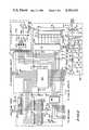
- FIG. 1is a combined schematic and block diagram of a time corrected, continuously updated clock in accordance with the present invention
- FIG. 2is a combined schematic and block diagram of a portion of the clock of FIG. 1 showing an arrangement for correcting and updating the reference clock signal of a microprocessor therein;
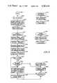
- FIG. 3is a simplified flow chart showing the steps carried out by a microprocessor in exercising control of the time corrected, continuously updated clock of the present invention.
- FIG. 4is a simplified flow chart showing the steps carried out by a microprocessor in interfacing the time corrected, continuously updated clock of the present invention with an accessory device to which the timing signal of the clock is provided.
- FIG. 1there is shown in simplified block and schematic diagram form a time corrected, continuously updated clock 10 in accordance with the present invention.
- time codewhich is decoded by the continuously updated clock 10 which displays the hour and minute information provided in the transmitted signal.
- the time codeis located 100 Hz from the carrier signal, i.e., at 5, 10, or 15 MHz, and is called the "subcarrier".
- the code pulsesare transmitted once every second in a modified IRIG-H format. After suitable identifiers are sent, the bits that make up the units, tens, and hundreds for minutes, hours, and days are sent sequentially. Certain pulses in succession comprise binary-coded groups which represent numbers.
- a position identifier pulseis transmitted which consists of 77 cycles of 100 Hz (770 milliseconds duration).
- the UTl corrections to the nearest 0.1 secondare broadcast via BCD pulses during the final 10 seconds of each frame and are termed control functions. These control functions indicate such things as whether the UTl correction is negative or positive, the amount of correction, and whether daylight saving time or standard time is in effect.
- the WWV/WWVH transmissionsalso include voice announcements.
- a tone decoder circuit 18 and a clock controller circuit 22which includes a clock microprocessor 80 for detecting and eliminating these errors in controlling clock operation.
- One frameis decoded by the tone decoder circuit 18 and stored electronically as digital bits in clock microprocessor 80.
- the next frameis received and stored in another location within clock microprocessor 80. If the two frames do not differ by exactly one minute, an error has occurred, and the continuously updated clock 10 will not use this information to correct its time.
- the first datais discarded and another try is made until several, i.e., three, successful decodes have been made.
- the continuously updated clock 10includes an RF receiver circuit 12 which is a heterodyne, amplitude modulated receiver, designed to receive the 5, 10, and 15 MHz WWV broadcast signals.
- the receiverincludes a telescoping internal antenna 14 as well as an external antenna connector 16 coupled to an RF amplifier 40.
- An amplified RF signalis provided to a mixer circuit 42 to which is also provided the reference frequency output of a local oscillator circuit 48.
- local oscillator 48provides a 5.455 MHz signal to mixer circuit 42 for mixing with the received RF signal.
- the 5 MHz WWV signalWhen the 5 MHz WWV signal is tuned to, the 5 MHz signal from the RF amplifier 40 and the 5.455 MHz signal from the local oscillator 48 are mixed in mixer circuit 42 to produce a difference frequency of 455 kHz (the IF frequency). This IF signal is then amplified and filtered in an IF amplifier and detector 44 for recovery of the 100 Hz and 1000 Hz tones from the WWV signal. These audible frequencies are coupled to a tone decoder circuit 18 as well as to an audio amplifier circuit 54 via a volume control comprised primarily of variable resistor 52.
- a clock microprocessor 80 within the clock controller circuit 22applies a 2-bit binary coded signal to a bandswitching circuit 50 within receiver 12. This causes the bandswitching circuit 50 to output an appropriate bandswitch signal to RF amplifier 40 in tuning to either the 5, 10 or 15 MHz WWV signal.
- bandswitching circuit 50By means of diode switching within bandswitching circuit 50, certain tuned circuits and crystals are selected within RF amplifier 40 and local oscillator 48 to permit the receiver 12 to receive the desired WWV channel.
- An automatic gain control (AGC) amplifier circuit 46is coupled to the RF amplifier 40 and the IF amplifier and detector 44 for filtering out the audio signal from the received RF signal while producing a DC voltage which is inversely related to the average amount of IF signal coupled to the IF amplifier and detector 44.
- This DC voltageis the AGC voltage and is used to control the gain of the RF amplifier 40 and the IF amplifier in maintaining a nearly constant audio signal level over wide variations in the received RF signal level.
- the AGC voltageis also coupled to a signal level comparator circuit 70 which assists the clock microprocessor 80 to determine which WWV channel is the strongest.
- the audio signalwhich passes through the volume control 52, is coupled to the input of an audio amplifier 54 which amplifies this signal and provides it to a speaker 58.
- the clock microprocessor 80provides a control signal to a mute circuit 56 for controlling audio amplifier 54 in either blocking audio signals from speaker 58 or permitting the audio portion of the received RF signal to be provided to and emitted from speaker 58.
- the primary function of the tone decoder circuit 18is to detect the 1000 Hz and 100 Hz tones sent on the WWV carrier signals.
- the receiver circuit 12detects the audio signals amplitude modulating (AM) the carrier.
- the audio signalis amplified by an audio preamplifier circuit 60 and is then provided to 100 and 1000 Hz active bandpass filters 62, 64.
- the 100 and 1000 Hz active bandpass filter circuits 62, 64reject some of the unwanted audio signals and amplify the desired 100 Hz and 1000 Hz signals, respectively.
- the 100 Hz toneis predominant and is passed by active bandpass filter 62 to a 100 Hz tone decoder 66.
- the 100 Hz tone decoder 66contains a phase locked loop (PLL) circuit (not shown) which has a voltage controlled oscillator (VCO, also not shown).
- PLLphase locked loop
- VCOvoltage controlled oscillator
- the output of the 100 Hz tone decoder 66will go low, causing the data light emitting diode (LED) 142 in the display circuit 32 to turn on and indicate to the clock microprocessor 80, which monitors the output of the 100 Hz tone decoder 66, that a 100 Hz signal is being received.
- the clock microprocessor 80also times the length that the tone is present to decide if it is a binary "0", "1", a 10 second marker, or an invalid signal.
- the 1000 Hz tone decoder 68detects at or near 1000 Hz when its VCO frequency is adjusted properly.
- the clock microprocessor 80monitors this output and also uses the information to determine when the beginning of a minute occurs, i.e., 00.0 seconds. If the clock microprocessor 80 determines that the proper 1000 Hz tone has occurred, it provides an output signal to an LED driver circuit 134 for illuminating the capture LED in a status LED display 140.
- the signal level comparator circuit 70 in the tone decoder 18compares eight different voltage levels from the clock microprocessor 80 with the receiver AGC voltage from the AGC amplifier 46. In response to this comparison, the signal level comparator circuit 70 indicates to the clock microprocessor 80 which receiver channel is receiving the best, or strongest, WWV signal. The manner in which this is accomplished is described in detail with respect to FIG. 2.
- the accessory interface system 20is provided for interfacing the continously updated clock 10 with such an accessory 21.
- the interface accessory system 20includes an accessory microprocessor 72 which receives time and date information from the clock microprocessor 80 in the clock controller circuit 22.
- Accessory 21requests the time and date from the accessory microprocessor 72 by sending a low-to-high transition signal via accessory interface circuit 74 to the accessory microprocessor 72.
- Accessory microprocessor 72senses this low voltage and sends the desired information to the accessory 21.
- Accessory microprocessor 72sends the time in the same format as displayed by the continuously updated clock 10, while date information is provided in Julian format, i.e., day of the year, with the accessory microprocessor 72 converting the date into a month/day format and reading the year select switch settings from a dip switch 76 to compute the year and correct the date for a leap year when necesssary.
- the accessory microprocessor 72checks other settings of the dip switch 76 to determine the baud rate and the number of stop bits to be used in the accessory serial information.
- Another accessory device 36such as a frequency counter may be coupled to the oscillator and amplifier circuit 90 in the clock controller 22 for receiving the reference oscillator output signal.
- a display circuit 32is coupled to and driven by the clock controller 22.
- the display circuit 32is multiplexed, with no more than one digit turned on at any given time. However, each digit therein is turned on approximately 100 times each second. This gives the appearance that all digits are turned on simultaneously.
- the clock microprocessor 80sends the appropriate BCD signals to a BCD-to-7-segment decoder and drive circuit 132 within the display circuit 32.
- the BCD-to-7-segment decoder and driver circuit 132decodes the signals into the 7-segment format of the LED digits in the digital display 138 and turns the appropriate segment driver pairs on.
- the clock microprocessor 80sends a 4-bit binary code to a binary-to-decimal decoder 86 within clock controller 22 and causes one of its output lines to turn on the desired digit driver transistor within a digit strobe driver circuit 130. This digit is turned on for approximately 1.25 milliseconds. Then the clock microprocessor 80 outputs different signals to light the next digit. This procedure is repeated again and again. Included in the display circuit 32 is a display ON/OFF switch 136 for turning the digital display 138 on and off to conserve power while permitting the clock to continue to operate.
- the individual LED indicators in the status LED display 140are energized via an LED driver circuit 134 by the clock microprocessor 80.
- the individual LED indicators in the status LED display 140are driven statically, i.e., they are either on or off as directed by their function and are not rapidly turned on and off like the aforementioned LED digits.
- the clock microprocessor 80decides which LED's in the status LED display 140 to turn on and supplies a high signal (approximately 5 VDC) to appropriate transistors within LED driver circuit 134 connected to the LED's to be lit.
- a DC power supply 24is coupled to either an AC source via plug 26 and line 28 or a DC source via input line 30.
- the DC power supply 24is coupled to and energizes the clock microprocessor 80.
- the clock microprocessor 80is a masked programmed Mostek 3870 microprocessor. Non-programmed versions of this microprocessor are available from Mostek Corporation of Carrollton, Tex.
- Microprocessor 80monitors the outputs of the 100 Hz and 1000 Hz tones from the 100 Hz and 1000 Hz tone decoders 66, 68, respectively.
- the 100 Hz tone decoder outputis provided to pin 38 of microprocessor 80, while the 1000 Hz tone decoder output is provided to pin 28 thereof.
- the time code signalis located 100 Hz from the carrier signal and is called the "subcarrier". These coded pulses are sent out once every second and are provided to pin 38 of microprocessor 80. Within a time frame of one minute, enough coded pulses are transmitted to convey, in BCD language, the current minute, hour, and day of the year. Two BCD groups are needed to show the hour and the minute (00 through 23 and 00 through 59); and three groups are needed to show the day of the year (001 through 366). When representing units, tens or hundreds, the basic 1-2-4-8 weights are simply multiplied by 1, 10 or 100 as appropriate.
- the coded informationalways refers to time at the beginning of the 1-minute frame and seconds can be determined by counting pulses within a given frame.
- Each framebegins with a unique spacing of pulses to mark the beginning of a new minute. No 100 Hz pulse is transmitted during the first seconds space, or a hole occurs in the pulse train at that time. Because all 100 Hz pulses in the time code are 30 milliseconds late with respect to UTC, each minute actually begins 1.03 seconds prior to the leading edge of the first 100 Hz tone in the new frame. For synchronization purposes, every 10 seconds a position identifier pulse is transmitted. Unlike the BCD pulses, the position identifiers consist of 77 cycles of 100 Hz. Microprocessor 80 decodes this timing information and provides it to various portions of the continuously updated clock 10 as described below.
- the regular WWV carrier at 5, 10 and 15 MHzuses a 1000 Hz amplitude modulating tone burst to signal the beginning of each minute.
- WWVH from Hawaiiuses a 1200 Hz amplitude modulating tone burst.
- This decoded tone burstis provided to pin 28 of microprocessor 80 from the 1000 Hz tone decoder 66 in the tone decoder circuit 18. It is this tone burst signal at the beginning of each minute which is used by the clock microprocessor 80 in its subsequent time keeping operation.
- the receipt of this 1000 Hz tone burstis used to increment counters (not shown) within the clock microprocessor 80 in measuring the passage of time from receipt of this 1000 Hz tone burst. This timing cycle is compared with an internal software timer within microprocessor 80.
- the clock microprocessor 80By thus comparing the clock rate at which it executes its operating program with a reference time signal, the clock microprocessor 80 is able to compare the frequency of its clock with a frequency standard. This comparison is performed internally within microprocessor 80 and, based upon the results of this comparison, microprocessor 80 provides various outputs to a binary-to-decimal decoder 86 and to a latch circuit 91. If a difference exists between the WWV reference time and the operating time of the clock microprocessor 80, the clock microprocessor 80 provides outputs via its P 0 port, pins 16-19, to latch circuit 91. In addition, clock microprocessor 80 provides various outputs via pins 3-6 to the A, B, C and D inputs of the binary-to-decimal decoder 86.
- the clock microprocessor 80outputs these signals only if the difference between the WWV reference time and its operating clock does not exceed a predetermined limit, i.e., 10 milliseconds. If this limit is exceeded, the clock microprocessor 80 merely updates its internal operating clock to coincide with the WWV reference time. This would typically occur when power is initially applied to the clock for it is then that the microprocessor's internal clock would, in general, differ by more than 10 milliseconds from the WWV reference time.
- a predetermined limiti.e. 10 milliseconds.
- the Q 8 output of binary-to-decimal decoder 86will go high to low providing an ST 1 (STROBE) input to latch circuit 91 causing the D 0 -D 3 inputs thereto to be latched therein.
- ST 1STROBE
- the Q 8 output therefromwill be switched from low to high, then when different inputs are placed on the A-D input pins, Q 8 goes low resulting in the latching of all four of the D 0 -D 3 inputs into latch circuit 91.
- a similar strobe signalis provided from the Q 9 output of decoder 86 to the ST 2 input of latch circuit 91 for latching data from the clock microprocessor into its D 4 -D 7 ports.
- Data representing a time correction signalis thus provided from the clock microprocessor's P 0 port, pins 16-19, to the D 0 -D 3 and D 4 -D 7 ports of latch circuit 91 in a multiplexed manner. Initially, a hexadecimal number in the middle of the frequency trimming range over which the clock microprocessor 80 is capable of selecting is latched into latch circuit 91.
- the number 127is provided to latch circuit 91 which represents the middle of the range of 0 to 255 over which the clock microprocessor 80 can correct using eight bits.
- the clock oscillator for clock microprocessor 80will be within 36 Hz of the desired 3.6 MHz internal time base frequency.
- the use of 256 bits, with each bit representing approximately 1 Hz,permits the clock microprocessor 80 to adjust its operating time approximately 120 Hz above and below the nominal clock oscillator frequency.
- Resistive ladder network 92includes a plurality of resistors and, in combination with latch circuit 91, serves as a digital-to-analog (D/A) converter in transforming the binary output from clock microprocessor 80 representing the difference between the microprocessor frequency and the received WWV reference frequency into an analog voltage representing this frequency difference.
- D/Adigital-to-analog
- NPN transistor 93serves as a buffer amplifier between the oscillator trim circuit 88 comprised of latch circuit 91 and resistive ladder network 92 and an oscillator circuit comprised primarily of a varactor diode 98, an oscillator crystal 100, and an NPN oscillator transistor 104.
- the output from the emitter of NPN transistor 93is provided to the cathode of varactor diode 98.
- the anode of varactor diode 98is connected to ground via resistor 99, reverse biasing varactor 98.
- This conditioncauses the junction of varactor diode 98 to act as a capacitor, whose capacitance is inversely related to the reverse bias voltage applied across the varactor diode. This capacitance affects the clock oscillator frequency and causes it to change slightly.
- Resistors 95, 96 and 99 and grounded capacitor 97provide a biasing function with respect to varactor diode 98, buffer amplifier 93 and oscillator crystal 100. In a preferred embodiment, the crystal oscillator oscillates at a nominal frequency of 3.6 MHz.
- Capacitors 105, 106 in combination with NPN transistor 104form a Colpitts oscillator with oscillator crystal 100 which oscillates at approximately 3.6 MHz.
- Capacitor 103provides power supply filtering, while resistors 101, 102 and 107 bias transistor 104.
- Capacitor 108provides AC coupling of the oscillator output of transistor 104 to the base of transistor 111.
- NPN transistor 111amplifies the output of transistor 104 and isolates transistor 104 from the load on transistor 111.
- Resistors 109 and 110perform a voltage dividing and biasing function with respect to NPN transistor 111, as do grounded resistor 113 and capacitor 114.
- NPN transistor 111serves as an amplifier and buffer in providing an adjusted time base reference signal via AC coupling capacitor 118 on line 77 to pin 2 of clock microprocessor 80. This adjusted time base signal sequences the clock microprocessor 80 through its functions.
- the adjusted time base signalis directly coupled to a complementary pair amplifier comprised of emitter-coupled PNP and NPN transistors 115, 116, which amplify and isolate the 3.6 MHz further so that it may be output via resistor 117 from the clock controller 22 and used as a reference frequency.
- the output of the 3.6 MHz oscillator amplifier circuitmay be provided via line 78 to an accessory device 36 which may, for example, be a frequency counter, for providing a timing reference signal thereto.
- the output from the adjusted timing signal oscillator and amplifier circuit 90may also be provided to an accessory interface system 20 for providing the time and date information serially to yet another accessory 21, such as a computer.
- the accessory interface system 20includes a microprocessor 72 which sends the time in the same format as presented in display circuit 32 via an interface circuit 74 to accessory 21.
- the date informationis provided from the clock controller 22 in Julian format, i.e., date of the year.
- the accessory microprocessor 72converts the date into a month/day format and reads the year select switch setting from the appropriate dip switch in switch assembly 76 to compute the year and correct the date for a leap year when necessary.
- the accessory microprocessor 72checks the other dip switch settings in switch assembly 76 to determine the baud rate and the number of stop bits to be used in the serial information provided from clock controller 22 via accessory interface system 20 to accessory 21.
- the pin 2 input of clock microprocessor 80is a frequency standard input and defines the rate at which the clock microprocessor executes the operating program stored therein.
- the adjusted time base signal provided to pin 2has been more closely synchronized with the beginning of the minute tone provided to the pin 28 input to the clock microprocessor 80 from the received WWV signal.
- Microprocessor timingis thus more closely synchronized with the received WWV signals by virtue of the 1000 Hz tone provided at the beginning of each minute and the adjusted microprocessor clock signal which has been more closely synchronized with the received WWV signal timing information. It is in this manner that clock 10 is updated with WWV timing information and is adjusted for more accurate operation in between receipt of the beginning of the minute audio tones received in the WWV signal.
- binary-to-decimal decoder 86has ten distinct outputs at Q 0 -Q 9 and four input lines at A-D.
- binary-to-decimal decoder 86decodes the binary value into a decimal value and causes the associated decimal output line to go high. Binary values greater than 9 are ignored and none of the output lines go high. An output line is not latched high and, therefore, an output will remain high only while the associated binary value is held on its input lines.
- the function of binary-to-decimal decoder 86is basically to expand the number of output lines of the clock microprocessor 80 from 4 to 10.
- the Q 6 output of binary-to-decimal decoder 86is coupled via resistor 83 to the base of NPN transistor 81 and provides for the turning on of transistor 81 to permit the clock microprocessor 80 to read the status of the eight switches in switch assembly 82 at its input lines 8-15.
- the Q 7 output of binary-to-decimal decoder 86is provided via resistor 89 to the base of NPN transistor 87 and allows clock microprocessor 80 to read the status of the eight switches in switch assembly 84 on the same input lines.
- the respective pluralities of diodes 71, 73 coupled to the outputs of switch assemblies 82 and 84provide isolation between the respective switch assemblies which use the same input pins of the clock microprocessor 80.
- the switches in switch assembly 82permit any one of 24 time zones to be selected and provide a manual channel lock out capability to prevent the clock from tuning to an undesired WWV frequency. This capability is provided to permit a user to prevent the clock from tuning to a frequency which is subject to local interference and may be particularly noisy resulting in degraded timing information.
- switch assembly 84is provided with propagation delay, daylight saving time/standard time, 12/24 hour, UTC 1 correction, and local/GMT time select switches. These manual switches permit the clock user to exercise greater control of clock operation and the information it provides.
- FIG. 2Also shown in FIG. 2 is a portion of the signal level comparator 70 which is coupled to the P 0 port, pins 3, 4 and 5, of the clock microprocessor 80.
- the clock microprocessor 80provides eight different 3-bit binary signals to diodes 120, 121 and 122 in signal level comparator 70.
- the voltage dividercomprised of resistors 123, 124, 125, 126 and 127 converts various combinations of these signals into eight different voltages. These voltages are applied via resistor 128 to the inverting input of a comparator 131.
- the presence of 100 Hz tonesis employed to give more "weight" to channels which are receiving these 100 Hz tones. This is done by Q403 and associated components.
- a +V voltageis coupled across the aforementioned resistive network by means of resistors 126 and 127.
- the receiver AGC voltage from the AGC amplifier 46is provided to the noninverting input of comparator 131. Whenever the AGC voltage is less than the divider voltage at the inverting input of comparator 131, the output of comparator 131 which is provided back to input pin 30 of the clock microprocessor 80 goes low.
- the clock microprocessor 80thus monitors the output voltage of comparator 131 within the signal level comparator circuit 70 of the tone decoder 18 and is thereby able to determine which of the three WWV channel levels is strongest.
- the clock microprocessor 80thus controls both the voltage of the divider circuit coupled across diodes 120, 121 and 122 and the receiving channel being used.
- FIG. 3there are shown various simplified flow charts illustrating the operation of the clock microprocessor 80 in exercising clock control in the four primary operations therein.
- the four primary operations controlled by the clock microprocessor 80include an initialization routine, the main operating program, and external and timer interrupt routines.
- an elliptical symbolindicates the start of an operational sequence
- a rectangleindicates an instruction or set of instructions resulting in the performance of a control function
- a diamondindicates a decision point based upon the comparison of binary signal inputs.
- the operating program of the clock microprocessor 80starts at step 200 and initially executes an initialization routine at step 202. ln the microprocessor initialization routine, its random access memory (RAM) is cleared, all of its ports are set so as to blank the display circuit 32, and various internal operating parameters are set to predetermined conditions at step 204. The operating program in the clock microprocessor 80 then proceeds to the start of the main operating program at step 206.
- RAMrandom access memory
- the microprocessor's main operating programis initiated at step 208 with an initial determination of whether the clock is in a test mode of operation made at step 210. If it is determined that the clock is not in a test mode of operation as established by switches within test circuit 34 coupled to the clock microprocessor 80, the program branches down to step 222. If at step 210 it is determined that the clock is in a test mode of operation, the operating program determines which test mode the clock is in. At step 212, test mode 1 is executed wherein all of the digits and LEDs in the display circuit 32 are illuminated.
- test mode 2at step 214 wherein a stop switch 35 in test circuit 34 is selected and digital display 32 should indicate 1000 if a 1000 Hz tone is generated with the AM LED illuminated when the 1000 Hz tone is detected.
- Test mode 3 at step 216is a similar test for the 1200 Hz WWVH signal.
- test mode 4is executed and the Julian date may be entered.
- the programexecutes test mode 5 wherein the UTC time may be manually entered.
- step 222received signal strength is recorded and each of the respective received signals is weighted accordingly.
- This checkinvolves monitoring the AGC voltage for each of the received channels. Each channel is scanned for 3 seconds, and the receiver is tuned to the strongest signal for approximately 15 seconds. If within this period, the clock acquires a capture signal, the beginning of the minute tone, the clock remains tuned to that channel for 1 minute or as long as it is receiving valid data.
- the programdetermines if the channel should be changed based upon whether the capture light in the status LED display 140 is illuminated. If at step 224 it is determined that the WWV channel should not be changed, the program branches to step 228. However, if at step 224 the program decides that the WWV channel should be changed, the audio amplifier 54 is muted so that the received WWV tones may not be heard, the channel to which the receiver circuit 12 is tuned is changed, and the appropriate LED in the display circuit 32 is illuminated to indicate which channel is now being received. At step 228, it is determined whether a complete frame of WWV data has been received and if not, the program branches to step 236.
- the programcompares the received data with previously received data at step 230 and if both sets of data agree, sets a WWV valid flag at step 232. If both sets of WWV data do not agree, the program stores the new data where the old data was stored and prepares for receipt of data in the next WWV frame.
- the programdetermines if 0.1 seconds has elapsed in order to update the displayed time by 0.1 seconds and monitor the setting of all the switches in the clock. If at step 236, it is determined that 1/10 of a second has not yet elapsed, the program branches to step 240 and determines if the WWV valid flag has been set. If the WWV valid flag has not been set, the program branches to step 246 and provides the Julian date to the accessory microprocessor 72 in the accessory interface system 20.
- the programIf at step 240 it is determined that the WWV valid flag has been set, the program resets the WWV valid flag, resynchronizes the display time if the clock time differs from the WWV reference time by more than 10 milliseconds, turns on the "HI SPEC" LED in the status LED display 140, and sets the "HI SPEC" timer at step 242.
- the programthen at step 244 corrects for differences between the clock time and received WWV time by actuating the oscillator trim circuit 88 and adjusting the operating program reference time to coincide with the received WWV reference time.
- the programupdates all annunciator LEDs in the display circuit 32 at step 248 and proceeds to the start of the main operating program at step 250.
- the external interrupt routine in the clock microprocessor 80is initiated at step 252 in response to illumination of the DATA LED on the status LED display 140.
- the operating program in the clock microprocessor 80times the widths of the data bursts provided in the received WWV signals to determine if the 100 Hz tone burst is a binary 0, a binary 1, or a 10 second marker. Once it is determined whether a received pulse is a 0 or a 1, it is stored in an appropriate RAM location within the clock microprocessor 80 at step 256 and the operating program exits to the main program at step 258.
- the timer interrupt routineis initiated at step 260 with a prescaler (not shown) in the clock microprocessor 80 set to determine when the timer interrupt routine will be periodically executed. Initially the timer interrupt routine increments the internal time in the clock mioroprocessor 80 by 1.25 milliseconds at step 262 and determines if the clock has been set at step 264. If the clock has not been set, the program branches to step 270 where it reads the switch settings in the clock and stores information representing the switch settings in appropriate registers in the clock microprocessor 80. If at step 264, the program determines that the clock has been set, the various LEDs in the display circuit 32 are each sequentially turned on for 1.25 milliseconds at step 266. The program then checks to see if valid WWV timing information has been received within the preceding 24 hours and, if not received, turns off the 1/10 second digit in digital display 138 indicating that the displayed timing data may be inaccurate.
- a prescalernot shown
- the programreads the various clock switch settings and stores this information in various registers within the clock microprocessor 80.
- the programdetermines whether a test mode has been selected by means of the appropriate switch in test circuit 34. If it is determined that a test mode has been selected, the program branches down to step 278 and exits the timer interrupt routine, returning to the main program at step 208 for executing the various test modes of operation. If at step 272 it is determined that a test mode has not been selected by means of test circuit 34, the program branches to step 274 and measures the width of the 1000 Hz tone bursts in order to detect a valid 1000 Hz signal tone marking the beginning of a one minute reference time interval.
- the programturns on the CAPTURE LED in the status LED display 140 and sets a 1 kHz tone flag within the clock microprocessor 80. With this flag set, the program will no longer look for a valid 1000 Hz tone burst each time the timer interrupt routine is executed. Therefore, the external interrupt routine will not be enabled unless this flag is set in the clock microprocessor 80 and the CAPTURE LED is illuminated. Also, if the 1 kHz tone flag is not set, the received WWV channel will not be changed and WWV timing data will not be compared with internal clock microprocessor timing since one complete frame of data has not yet been received. When the CAPTURE LED flag is initially set at step 276, the previously received timing data is incremented by one minute. Once the CAPTURE LED is turned on at step 276, the program proceeds to step 278, exiting the timer interrupt routine and returning to the main operating program.
- FIG. 4there are shown several flow charts illustrating the operation of the accessory interface system 20 under the control of the accessory microprocessor 72.
- the four routines illustrated in the various flow charts in FIG. 4 for the accessory microprocessor 72are similar to those previously discussed with respect to FIG. 3 and the clock microprocessor 80.
- Accessory microprocessor 72 operationis briefly described in the following paragraphs with respect to the flow charts of FIG. 4.
- the program executed by the accessory microprocessor 72is initiated at step 280 and begins with an initialization routine at step 282 wherein its random access memory (RAM) is cleared, all ports are set to a predetermined state, and various internal parameters are set within the accessory microprocessor 72 at step 284.
- the programthen at step 286 proceeds to the start of the main operating program and begins executing the main operating program at step 288.
- the first step in the main operating programinvolves the receipt of time and date data from the clock microprocessor 80 at step 290 whereupon the accessory microprocessor 72 converts the time data to ASCII format at step 292.
- the programthen decodes AM/PM information at step 294 and computes the year from the position of dip switches in the switch assembly 76 at step 296.
- the date received from the clock microprocessor 80is then converted from Julian to a Gregorian date and put into ASCII format at step 298.
- the programthen at step 300 determines if the accessory interface system is in an automatic mode and, if so, branches to step 304 where a timer in the accessory microprocessor 72 is set according to the position of a baud rate dip switch in switch assembly 76 and a timer interrupt is enabled.
- the accessory microprocessor 72then provides the ASCII character to the interface circuit 74 at step 312 for transmission to the accessory device 21 and continues to provide data for transmission to the interface circuit 74 until the program determines at step 310 that all data has been sent. Once it is determined that all the data has been transmitted to the accessory device 21, the timer interrupt routine is disabled at step 308 and the program returns to the start of the main operating program at step 306. If at step 300 it is determined that the accessory interface system 20 is not in the automatic mode of operation, the program then determines whether a request to send data has been received from accessory device 21 at step 302. If a request for data has been received, the program branches to step 304 and prepares to send the requested time and data data to accessory device 21. lf a request for data has not been received from accessory device 21, the program branches to step 306 and returns to the start of the main operating program.
- An external interrupt routineis initiated at step 314 and involves the setting of a request-to-send flag in the accessory microprocessor 72 at step 316 in preparation for the transmission of time and date data to the accessory device 21.
- the external interrupt routinethen returns to the main operating program at step 318.
- a timer interrupt routineis initiated at step 320 and involves the transmission of data in the form of ASCII character at step 322 from the accessory interface system 20 to the accessory device 21. After each bit of data is transmitted to accessory device 21, the timer interrupt routine returns to the main operating program at step 324.
Landscapes
- Physics & Mathematics (AREA)
- General Physics & Mathematics (AREA)
- Electric Clocks (AREA)
Abstract
Description
Claims (15)
Priority Applications (1)
| Application Number | Priority Date | Filing Date | Title |
|---|---|---|---|
| US06/602,844US4582434A (en) | 1984-04-23 | 1984-04-23 | Time corrected, continuously updated clock |
Applications Claiming Priority (1)
| Application Number | Priority Date | Filing Date | Title |
|---|---|---|---|
| US06/602,844US4582434A (en) | 1984-04-23 | 1984-04-23 | Time corrected, continuously updated clock |
Publications (1)
| Publication Number | Publication Date |
|---|---|
| US4582434Atrue US4582434A (en) | 1986-04-15 |
Family
ID=24413025
Family Applications (1)
| Application Number | Title | Priority Date | Filing Date |
|---|---|---|---|
| US06/602,844Expired - Fee RelatedUS4582434A (en) | 1984-04-23 | 1984-04-23 | Time corrected, continuously updated clock |
Country Status (1)
| Country | Link |
|---|---|
| US (1) | US4582434A (en) |
Cited By (90)
| Publication number | Priority date | Publication date | Assignee | Title |
|---|---|---|---|---|
| US4768178A (en)* | 1987-02-24 | 1988-08-30 | Precision Standard Time, Inc. | High precision radio signal controlled continuously updated digital clock |
| US4823328A (en)* | 1987-08-27 | 1989-04-18 | Conklin Charles C | Radio signal controlled digital clock |
| US4885778A (en)* | 1984-11-30 | 1989-12-05 | Weiss Kenneth P | Method and apparatus for synchronizing generation of separate, free running, time dependent equipment |
| US4899117A (en)* | 1987-12-24 | 1990-02-06 | The United States Of America As Represented By The Secretary Of The Army | High accuracy frequency standard and clock system |
| US4920365A (en)* | 1988-04-25 | 1990-04-24 | Siemens Aktiengesellschaft | Electronic digital timepiece having a separate key for controlling the switching of the display from standard to daylight savings time |
| WO1990004814A1 (en)* | 1988-10-26 | 1990-05-03 | Eagle River Industries, Inc. | Event clock with automatic daylight saving adjustment |
| US4933920A (en)* | 1988-12-19 | 1990-06-12 | Irwin Sternberg | Sidereal clock |
| US4993003A (en)* | 1988-08-17 | 1991-02-12 | Electronic-Werke Deutschland Gmbh | Apparatus for updating time-of-day information in a signal |
| US4998279A (en)* | 1984-11-30 | 1991-03-05 | Weiss Kenneth P | Method and apparatus for personal verification utilizing nonpredictable codes and biocharacteristics |
| GB2238438A (en)* | 1989-11-20 | 1991-05-29 | Pioneer Electronic Corp | Radio data system receiver with clock time function |
| US5036500A (en)* | 1988-12-20 | 1991-07-30 | Junghans Uhren Gmbh | Autonomous radio time piece having a resettable receiver actuation switch |
| DE4002723A1 (en)* | 1990-01-31 | 1991-08-01 | Junghans Uhren Gmbh | AUTONOMOUS RADIO WATCH |
| WO1991011763A1 (en)* | 1990-01-29 | 1991-08-08 | The United States Of America, Represented By The Secretary, United States Department Of Commerce | Device and method for providing accurate time and/or frequency |
| WO1991016670A1 (en)* | 1990-04-18 | 1991-10-31 | At&E Corporation | Method and apparatus for accurate time maintenance and display |
| US5068838A (en)* | 1990-07-18 | 1991-11-26 | Klausner Patent Technologies | Location acquisition and time adjusting system |
| US5077706A (en)* | 1988-12-08 | 1991-12-31 | Junghans Uhren Gmbh | Autonomous radio timepiece capable of automatic correction regardless of time zone changes |
| WO1992001978A1 (en)* | 1990-07-18 | 1992-02-06 | Klausner Patent Technologies | Location acquisition and time adjusting system |
| US5105396A (en)* | 1990-05-04 | 1992-04-14 | Junghans Uhren Gmbh | Autonomous radio timepiece |
| US5138707A (en)* | 1989-01-05 | 1992-08-11 | International Business Machines Corporation | Method of operating a timer in a digital data processing system |
| US5168520A (en)* | 1984-11-30 | 1992-12-01 | Security Dynamics Technologies, Inc. | Method and apparatus for personal identification |
| US5237614A (en)* | 1991-06-07 | 1993-08-17 | Security Dynamics Technologies, Inc. | Integrated network security system |
| US5265070A (en)* | 1989-11-08 | 1993-11-23 | Seiko Epson Corporation | Receiving device with timekeeping function |
| US5297120A (en)* | 1992-03-04 | 1994-03-22 | Seiko Instruments Inc. | Radio wave-standardized electronic timepiece |
| US5329500A (en)* | 1993-02-18 | 1994-07-12 | Goldstar Co., Ltd. | Video cassette recorder having automatic time setting function |
| US5367572A (en)* | 1984-11-30 | 1994-11-22 | Weiss Kenneth P | Method and apparatus for personal identification |
| WO1994028433A1 (en)* | 1993-05-27 | 1994-12-08 | Stellar Gps Corporation | Gps synchronized frequency/time source |
| EP0564220A3 (en)* | 1992-03-31 | 1995-01-18 | Glenayre Electronics Inc | Clock synchronization system |
| US5422863A (en)* | 1989-11-08 | 1995-06-06 | Seiko Epson Corporation | Automatically correcting electronic timepiece for selected signal receiving wireless receiver |
| US5469411A (en)* | 1990-04-18 | 1995-11-21 | Seiko Communications Holding N.V. | Method and apparatus for accurate time maintenance and display |
| EP0553722A3 (en)* | 1992-01-28 | 1995-12-13 | Junghans Uhren Gmbh | Small autonomous radio timepiece with analogue display, in particular wristwatch radio |
| DE29519951U1 (en)* | 1995-12-18 | 1996-05-15 | Conrad Electronic GmbH, 92242 Hirschau | Radio clock radio alarm clock, especially RDS radio clock radio |
| US5557585A (en)* | 1993-08-25 | 1996-09-17 | Sony Corp. | Broadcast signal receiver which automatically sets an internal clock |
| US5596552A (en)* | 1990-12-31 | 1997-01-21 | Samsung Electronics Co., Ltd. | Circuit for resetting time of timer |
| US5621703A (en)* | 1993-12-01 | 1997-04-15 | Seiko Instruments Inc. | Radio wave-corrected timepiece |
| US5657297A (en)* | 1994-01-28 | 1997-08-12 | Fujitsu Limited | Clock apparatus having high accuracy |
| US5757786A (en)* | 1993-12-27 | 1998-05-26 | Hyundai Electronics Industries Co., Ltd. | Time synchronization apparatus and a method thereof using a global positioning system of a satellite |
| US5881022A (en)* | 1996-01-11 | 1999-03-09 | Illinois Information Technology Corporation | Frequency shifing device and method for automatic clock adjustment |
| US5901115A (en)* | 1996-04-18 | 1999-05-04 | Helmut Hechinger Gmbh & Co. | Analog radio clock with time zone conversion |
| US5899957A (en)* | 1994-01-03 | 1999-05-04 | Trimble Navigation, Ltd. | Carrier phase differential GPS corrections network |
| US5921938A (en)* | 1997-10-09 | 1999-07-13 | Physio-Control Manufacturing Corporation | System and method for adjusting time associated with medical event data |
| US5940458A (en)* | 1997-05-10 | 1999-08-17 | Hyundai Electronics Industries Co., Ltd. | Method and compensating for time error of time/frequency generator using global positioning system |
| US5970400A (en)* | 1996-04-30 | 1999-10-19 | Magellan Corporation | Adjusting the timing and synchronization of a radio's oscillator with a signal from an SATPS satellite |
| WO1999061960A1 (en)* | 1998-05-25 | 1999-12-02 | Nanyang Polytechnic | Wireless synchronous clock system |
| WO2000007077A1 (en)* | 1998-07-31 | 2000-02-10 | Intel Corporation | Method and apparatus for providing certified time |
| US6069850A (en)* | 1998-03-18 | 2000-05-30 | International Business Machines Corporation | Method and apparatus for driving a battery-backed up clock while a system is powered-down |
| US6128337A (en)* | 1997-05-29 | 2000-10-03 | Trimble Navigation Limited | Multipath signal discrimination |
| US6205091B1 (en)* | 1997-10-17 | 2001-03-20 | Junghans Uhren Gmbh | Method and apparatus for controlling a solar-powered radio-controlled timepiece when a storage element is inadequately charged |
| US20020099811A1 (en)* | 2000-12-06 | 2002-07-25 | Hideyuki Takeda | Time managing apparatus for managing time to synchronize with other apparatuses |
| EP1028535A4 (en)* | 1998-06-09 | 2002-11-20 | Matsushita Electric Industrial Co Ltd | BROADCASTING RECEIVER |
| US20030063525A1 (en)* | 2001-09-28 | 2003-04-03 | Ken Richardson | Microprocessor controlled quartz analog clock movement |
| US20030067844A1 (en)* | 2001-10-04 | 2003-04-10 | Kuo-Ming Liaw | System and method of updating local time in different time zones |
| US6556512B1 (en)* | 1999-10-20 | 2003-04-29 | Sony International (Europe) Gmbh | Mobile terminal for a wireless telecommunication system with accurate real time generation |
| US20030105964A1 (en)* | 2001-12-04 | 2003-06-05 | Brainard John G. | Method and apparatus for performing enhanced time-based authentication |
| US20030132809A1 (en)* | 2002-01-17 | 2003-07-17 | Chinnugounder Senthilkumar | Oscillator with tunable capacitor |
| US20030169642A1 (en)* | 2002-03-08 | 2003-09-11 | Quartex, Inc., A Division Of Primex, Inc. | Time keeping system with automatic daylight savings time adjustment |
| US20030169641A1 (en)* | 2002-03-08 | 2003-09-11 | Quartex A Division Of Primex, Inc. | Time keeping system with automatic daylight savings time adjustment |
| US6680877B1 (en) | 2003-01-24 | 2004-01-20 | Richard M. Lienau | Solar night splitter and event timer |
| US20040022131A1 (en)* | 2002-05-24 | 2004-02-05 | Keith Kibiloski | Radio-controlled clock |
| US6748451B2 (en) | 1998-05-26 | 2004-06-08 | Dow Global Technologies Inc. | Distributed computing environment using real-time scheduling logic and time deterministic architecture |
| US20040127234A1 (en)* | 2001-04-27 | 2004-07-01 | Gerrits Johannes F. | Timekeeper with automatic time setting and time setting method for same |
| US20040167739A1 (en)* | 2003-01-03 | 2004-08-26 | Ilan Shemesh | Clock diagnostics |
| US20040172663A1 (en)* | 2003-02-28 | 2004-09-02 | Orion Electric Company Ltd. | Video receiver |
| US6799116B2 (en) | 2000-12-15 | 2004-09-28 | Trimble Navigation Limited | GPS correction methods, apparatus and signals |
| US20040202051A1 (en)* | 2001-09-10 | 2004-10-14 | Takashi Ihara | Radio corrected clock |
| US20050024157A1 (en)* | 2003-07-21 | 2005-02-03 | Duven Dennis J. | Adaptive Kalman Filter Process for controlling an ensemble clock |
| US20050058157A1 (en)* | 2001-09-21 | 2005-03-17 | Quartex, Inc. | Wireless synchronous time system |
| US20050094495A1 (en)* | 2002-09-06 | 2005-05-05 | Akinari Takada | Radio controlled timepiece and method of controlling the same |
| US20050111304A1 (en)* | 2001-09-21 | 2005-05-26 | Quartex, Inc. | Wireless synchronous time system |
| US20050122952A1 (en)* | 2003-12-08 | 2005-06-09 | Atmel Germany Gmbh | Radio-controlled clock and method for automatically receiving and evaluating any one of plural available time signals |
| US20050131735A1 (en)* | 2003-12-15 | 2005-06-16 | Degeorge Michael P. | Computerized system and method for identifying and storing time zone information in a healthcare environment |
| US20050213433A1 (en)* | 2004-03-24 | 2005-09-29 | Mah Pat Y | Localized signal radio adjusted clock |
| WO2005109120A1 (en)* | 2004-04-15 | 2005-11-17 | Junghans Uhren Gmbh | Radio-controlled wristwatch with means for decoding signals from time signal transmitters from a number of time zones |
| US6985583B1 (en) | 1999-05-04 | 2006-01-10 | Rsa Security Inc. | System and method for authentication seed distribution |
| US20060058926A1 (en)* | 2001-09-21 | 2006-03-16 | Quartex, A Division Of Primex, Inc. | Wireless synchronous time system with solar powered transceiver |
| US20060064244A1 (en)* | 1994-01-03 | 2006-03-23 | Robbins James E | Differential GPS corrections using virtual stations |
| DE102004050242A1 (en)* | 2004-10-15 | 2006-04-27 | Heinz Rinderle | Time control for electronic clock e.g. wrist clock, has additional time measuring system which determines time deviations, where data for error correction is derived from deviation, and error correction is executed automatically |
| US20060158963A1 (en)* | 2001-09-21 | 2006-07-20 | Quartex, Inc., A Division Of Primex, Inc. | Time keeping system with automatic daylight savings time adjustment |
| US20060259806A1 (en)* | 2005-05-12 | 2006-11-16 | Schweitzer Eng. Laboratories, Inc. | Self-calibrating time code generator |
| US20070174614A1 (en)* | 2005-02-18 | 2007-07-26 | Rsa Security Inc. | Derivative seeds |
| US20070202801A1 (en)* | 2006-02-27 | 2007-08-30 | Frantz Frederick E | System and Method for Synchronization of a Plurality of Devices in a Wireless Sensor Arrangement |
| US20070286028A1 (en)* | 2006-06-08 | 2007-12-13 | David Meltzer | Radio Watch |
| US20080112269A1 (en)* | 2006-11-14 | 2008-05-15 | Frank Edward Lawton | Time Broadcast Receiving Time Clock |
| EP1835365A3 (en)* | 2006-03-17 | 2008-05-28 | Görlitz AG | Method for adjusting the internal clock of an energy measuring device |
| US7433274B1 (en)* | 2006-11-20 | 2008-10-07 | Bath Eugene R | Rapid set handicapped alarm clock |
| US20090129208A1 (en)* | 2009-01-28 | 2009-05-21 | Weiss Kenneth P | Apparatus, system and method for keeping time |
| CN101986555A (en)* | 2009-07-06 | 2011-03-16 | 北方电讯网络有限公司 | System and method for built in self test for timing module holdover |
| US20130007734A1 (en)* | 2011-06-30 | 2013-01-03 | International Business Machines Corporation | System, method and computer program product for virtual machine allocation |
| USRE45514E1 (en) | 1997-02-13 | 2015-05-12 | La Crosse Technology Ip Holdings, Llc | Severe weather detector and alarm |
| CN106125154A (en)* | 2016-08-31 | 2016-11-16 | 苏州华芯微电子股份有限公司 | A kind of timing method for pyroelectric infrared human body induction apparatus and device thereof |
| US10466655B1 (en)* | 2018-12-27 | 2019-11-05 | Seiko Epson Corporation | Electronic timepiece and control method of electronic timepiece |
Citations (4)
| Publication number | Priority date | Publication date | Assignee | Title |
|---|---|---|---|---|
| US3530663A (en)* | 1967-09-01 | 1970-09-29 | Patek Philippe Sa | Automatic and continuous time adjusting device for a clock |
| US4117661A (en)* | 1975-03-10 | 1978-10-03 | Bryant Jr Ellis H | Precision automatic local time decoding apparatus |
| US4234958A (en)* | 1977-06-16 | 1980-11-18 | Lathem Time Recorder Co., Inc. | Radio synchronized time-keeping apparatus and method |
| US4440501A (en)* | 1980-06-19 | 1984-04-03 | Werner Schulz | Method of automatic adjustment of self-contained radio-clock by means of time mark |
- 1984
- 1984-04-23USUS06/602,844patent/US4582434A/ennot_activeExpired - Fee Related
Patent Citations (4)
| Publication number | Priority date | Publication date | Assignee | Title |
|---|---|---|---|---|
| US3530663A (en)* | 1967-09-01 | 1970-09-29 | Patek Philippe Sa | Automatic and continuous time adjusting device for a clock |
| US4117661A (en)* | 1975-03-10 | 1978-10-03 | Bryant Jr Ellis H | Precision automatic local time decoding apparatus |
| US4234958A (en)* | 1977-06-16 | 1980-11-18 | Lathem Time Recorder Co., Inc. | Radio synchronized time-keeping apparatus and method |
| US4440501A (en)* | 1980-06-19 | 1984-04-03 | Werner Schulz | Method of automatic adjustment of self-contained radio-clock by means of time mark |
Cited By (158)
| Publication number | Priority date | Publication date | Assignee | Title |
|---|---|---|---|---|
| US4998279A (en)* | 1984-11-30 | 1991-03-05 | Weiss Kenneth P | Method and apparatus for personal verification utilizing nonpredictable codes and biocharacteristics |
| US4885778A (en)* | 1984-11-30 | 1989-12-05 | Weiss Kenneth P | Method and apparatus for synchronizing generation of separate, free running, time dependent equipment |
| US5168520A (en)* | 1984-11-30 | 1992-12-01 | Security Dynamics Technologies, Inc. | Method and apparatus for personal identification |
| US5367572A (en)* | 1984-11-30 | 1994-11-22 | Weiss Kenneth P | Method and apparatus for personal identification |
| US5023908A (en)* | 1984-11-30 | 1991-06-11 | Kenneth Weiss | Method and apparatus for personal identification |
| US4768178A (en)* | 1987-02-24 | 1988-08-30 | Precision Standard Time, Inc. | High precision radio signal controlled continuously updated digital clock |
| US4823328A (en)* | 1987-08-27 | 1989-04-18 | Conklin Charles C | Radio signal controlled digital clock |
| US4899117A (en)* | 1987-12-24 | 1990-02-06 | The United States Of America As Represented By The Secretary Of The Army | High accuracy frequency standard and clock system |
| US4920365A (en)* | 1988-04-25 | 1990-04-24 | Siemens Aktiengesellschaft | Electronic digital timepiece having a separate key for controlling the switching of the display from standard to daylight savings time |
| US4993003A (en)* | 1988-08-17 | 1991-02-12 | Electronic-Werke Deutschland Gmbh | Apparatus for updating time-of-day information in a signal |
| WO1990004814A1 (en)* | 1988-10-26 | 1990-05-03 | Eagle River Industries, Inc. | Event clock with automatic daylight saving adjustment |
| US5077706A (en)* | 1988-12-08 | 1991-12-31 | Junghans Uhren Gmbh | Autonomous radio timepiece capable of automatic correction regardless of time zone changes |
| US4933920A (en)* | 1988-12-19 | 1990-06-12 | Irwin Sternberg | Sidereal clock |
| US5036500A (en)* | 1988-12-20 | 1991-07-30 | Junghans Uhren Gmbh | Autonomous radio time piece having a resettable receiver actuation switch |
| US5138707A (en)* | 1989-01-05 | 1992-08-11 | International Business Machines Corporation | Method of operating a timer in a digital data processing system |
| US5422863A (en)* | 1989-11-08 | 1995-06-06 | Seiko Epson Corporation | Automatically correcting electronic timepiece for selected signal receiving wireless receiver |
| US5265070A (en)* | 1989-11-08 | 1993-11-23 | Seiko Epson Corporation | Receiving device with timekeeping function |
| GB2238438A (en)* | 1989-11-20 | 1991-05-29 | Pioneer Electronic Corp | Radio data system receiver with clock time function |
| GB2238438B (en)* | 1989-11-20 | 1994-07-20 | Pioneer Electronic Corp | Radio data system receiver |
| US5274545A (en)* | 1990-01-29 | 1993-12-28 | The United States Of America As Represented By The Secretary Of Commerce | Device and method for providing accurate time and/or frequency |
| WO1991011763A1 (en)* | 1990-01-29 | 1991-08-08 | The United States Of America, Represented By The Secretary, United States Department Of Commerce | Device and method for providing accurate time and/or frequency |
| DE4002723C2 (en)* | 1990-01-31 | 2003-06-26 | Junghans Uhren Gmbh | Autonomous radio clock |
| DE4002723A1 (en)* | 1990-01-31 | 1991-08-01 | Junghans Uhren Gmbh | AUTONOMOUS RADIO WATCH |
| US5448533A (en)* | 1990-04-18 | 1995-09-05 | Seiko Corporation | Method and apparatus for accurate time maintenance and display |
| WO1991016670A1 (en)* | 1990-04-18 | 1991-10-31 | At&E Corporation | Method and apparatus for accurate time maintenance and display |
| US5469411A (en)* | 1990-04-18 | 1995-11-21 | Seiko Communications Holding N.V. | Method and apparatus for accurate time maintenance and display |
| US5105396A (en)* | 1990-05-04 | 1992-04-14 | Junghans Uhren Gmbh | Autonomous radio timepiece |
| US5068838A (en)* | 1990-07-18 | 1991-11-26 | Klausner Patent Technologies | Location acquisition and time adjusting system |
| WO1992001978A1 (en)* | 1990-07-18 | 1992-02-06 | Klausner Patent Technologies | Location acquisition and time adjusting system |
| US5375018A (en)* | 1990-07-18 | 1994-12-20 | Klausner Patent Technologies | Location acquisition and time adjusting system |
| US5596552A (en)* | 1990-12-31 | 1997-01-21 | Samsung Electronics Co., Ltd. | Circuit for resetting time of timer |
| US5237614A (en)* | 1991-06-07 | 1993-08-17 | Security Dynamics Technologies, Inc. | Integrated network security system |
| EP0553722A3 (en)* | 1992-01-28 | 1995-12-13 | Junghans Uhren Gmbh | Small autonomous radio timepiece with analogue display, in particular wristwatch radio |
| US5297120A (en)* | 1992-03-04 | 1994-03-22 | Seiko Instruments Inc. | Radio wave-standardized electronic timepiece |
| EP0564220A3 (en)* | 1992-03-31 | 1995-01-18 | Glenayre Electronics Inc | Clock synchronization system |
| US5329500A (en)* | 1993-02-18 | 1994-07-12 | Goldstar Co., Ltd. | Video cassette recorder having automatic time setting function |
| US5440313A (en)* | 1993-05-27 | 1995-08-08 | Stellar Gps Corporation | GPS synchronized frequency/time source |
| WO1994028433A1 (en)* | 1993-05-27 | 1994-12-08 | Stellar Gps Corporation | Gps synchronized frequency/time source |
| US5557585A (en)* | 1993-08-25 | 1996-09-17 | Sony Corp. | Broadcast signal receiver which automatically sets an internal clock |
| US5621703A (en)* | 1993-12-01 | 1997-04-15 | Seiko Instruments Inc. | Radio wave-corrected timepiece |
| US5757786A (en)* | 1993-12-27 | 1998-05-26 | Hyundai Electronics Industries Co., Ltd. | Time synchronization apparatus and a method thereof using a global positioning system of a satellite |
| US5899957A (en)* | 1994-01-03 | 1999-05-04 | Trimble Navigation, Ltd. | Carrier phase differential GPS corrections network |
| US7711480B2 (en) | 1994-01-03 | 2010-05-04 | Trimble Navigation Limited | Differential GPS corrections using virtual stations |
| US20060282216A1 (en)* | 1994-01-03 | 2006-12-14 | Robbins James E | Differential GPS corrections using virtual stations |
| US20060064244A1 (en)* | 1994-01-03 | 2006-03-23 | Robbins James E | Differential GPS corrections using virtual stations |
| US5657297A (en)* | 1994-01-28 | 1997-08-12 | Fujitsu Limited | Clock apparatus having high accuracy |
| DE29519951U1 (en)* | 1995-12-18 | 1996-05-15 | Conrad Electronic GmbH, 92242 Hirschau | Radio clock radio alarm clock, especially RDS radio clock radio |
| US5881022A (en)* | 1996-01-11 | 1999-03-09 | Illinois Information Technology Corporation | Frequency shifing device and method for automatic clock adjustment |
| US5901115A (en)* | 1996-04-18 | 1999-05-04 | Helmut Hechinger Gmbh & Co. | Analog radio clock with time zone conversion |
| US5970400A (en)* | 1996-04-30 | 1999-10-19 | Magellan Corporation | Adjusting the timing and synchronization of a radio's oscillator with a signal from an SATPS satellite |
| USRE45514E1 (en) | 1997-02-13 | 2015-05-12 | La Crosse Technology Ip Holdings, Llc | Severe weather detector and alarm |
| US5940458A (en)* | 1997-05-10 | 1999-08-17 | Hyundai Electronics Industries Co., Ltd. | Method and compensating for time error of time/frequency generator using global positioning system |
| US6128337A (en)* | 1997-05-29 | 2000-10-03 | Trimble Navigation Limited | Multipath signal discrimination |
| US5921938A (en)* | 1997-10-09 | 1999-07-13 | Physio-Control Manufacturing Corporation | System and method for adjusting time associated with medical event data |
| US6205091B1 (en)* | 1997-10-17 | 2001-03-20 | Junghans Uhren Gmbh | Method and apparatus for controlling a solar-powered radio-controlled timepiece when a storage element is inadequately charged |
| US6069850A (en)* | 1998-03-18 | 2000-05-30 | International Business Machines Corporation | Method and apparatus for driving a battery-backed up clock while a system is powered-down |
| WO1999061960A1 (en)* | 1998-05-25 | 1999-12-02 | Nanyang Polytechnic | Wireless synchronous clock system |
| SG81231A1 (en)* | 1998-05-25 | 2001-06-19 | Nanyang Polytechnic | Wireless synchronous clock system |
| US6748451B2 (en) | 1998-05-26 | 2004-06-08 | Dow Global Technologies Inc. | Distributed computing environment using real-time scheduling logic and time deterministic architecture |
| EP1028535A4 (en)* | 1998-06-09 | 2002-11-20 | Matsushita Electric Industrial Co Ltd | BROADCASTING RECEIVER |
| US6552752B1 (en) | 1998-06-09 | 2003-04-22 | Matsushita Electric Industrial Co., Ltd. | Clock generating based on a reference signal included in the digital input data of a digital broadcasting receiver |
| WO2000007077A1 (en)* | 1998-07-31 | 2000-02-10 | Intel Corporation | Method and apparatus for providing certified time |
| US6532194B2 (en)* | 1998-07-31 | 2003-03-11 | Intel Corporation | Method and apparatus for providing certified time |
| US7502467B2 (en) | 1999-05-04 | 2009-03-10 | Rsa Security Inc. | System and method for authentication seed distribution |
| US20060256961A1 (en)* | 1999-05-04 | 2006-11-16 | Rsa Security Inc. | System and method for authentication seed distribution |
| US6985583B1 (en) | 1999-05-04 | 2006-01-10 | Rsa Security Inc. | System and method for authentication seed distribution |
| US6556512B1 (en)* | 1999-10-20 | 2003-04-29 | Sony International (Europe) Gmbh | Mobile terminal for a wireless telecommunication system with accurate real time generation |
| US7281061B2 (en)* | 2000-12-06 | 2007-10-09 | Matsushita Electric Industrial Co., Ltd. | Time managing apparatus for managing time to synchronize with other apparatuses |
| US20020099811A1 (en)* | 2000-12-06 | 2002-07-25 | Hideyuki Takeda | Time managing apparatus for managing time to synchronize with other apparatuses |
| US6862526B2 (en) | 2000-12-15 | 2005-03-01 | Trimble Navigation Limited | GPS correction methods, apparatus and signals |
| US6799116B2 (en) | 2000-12-15 | 2004-09-28 | Trimble Navigation Limited | GPS correction methods, apparatus and signals |
| US20040204852A1 (en)* | 2000-12-15 | 2004-10-14 | Robbins James E. | GPS correction methods, apparatus and signals |
| US7031696B2 (en)* | 2001-04-27 | 2006-04-18 | Csem Centre Suisse D'electronique Et De Microtechnique Sa-Recherche Et Developpement | Timekeeper with automatic time setting and time setting method for same |
| US20040127234A1 (en)* | 2001-04-27 | 2004-07-01 | Gerrits Johannes F. | Timekeeper with automatic time setting and time setting method for same |
| US7408845B2 (en)* | 2001-09-10 | 2008-08-05 | Citizen Holdings Co., Ltd. | Radio corrected clock |
| US20040202051A1 (en)* | 2001-09-10 | 2004-10-14 | Takashi Ihara | Radio corrected clock |
| US20050058157A1 (en)* | 2001-09-21 | 2005-03-17 | Quartex, Inc. | Wireless synchronous time system |
| US7499379B2 (en) | 2001-09-21 | 2009-03-03 | Quartex, Division Of Primax, Inc. | Wireless synchronous time system |
| US20060158963A1 (en)* | 2001-09-21 | 2006-07-20 | Quartex, Inc., A Division Of Primex, Inc. | Time keeping system with automatic daylight savings time adjustment |
| US20080198698A1 (en)* | 2001-09-21 | 2008-08-21 | Pikula Michael A | Wireless synchronous time system |
| US20080212413A1 (en)* | 2001-09-21 | 2008-09-04 | Pikula Michael A | Wireless synchronous time system |
| US20050111304A1 (en)* | 2001-09-21 | 2005-05-26 | Quartex, Inc. | Wireless synchronous time system |
| US7539085B2 (en) | 2001-09-21 | 2009-05-26 | Quartex, Division Of Primex, Inc. | Wireless synchronous time system |
| US7411869B2 (en) | 2001-09-21 | 2008-08-12 | Quartex, Division Of Primex, Inc. | Wireless synchronous time system |
| US7369462B2 (en) | 2001-09-21 | 2008-05-06 | Quartex, Division Of Primex, Inc. | Wireless synchronous time system with solar powered transceiver |
| US20080212412A1 (en)* | 2001-09-21 | 2008-09-04 | Pikula Michael A | Wireless synchronous time system |
| US7480210B2 (en) | 2001-09-21 | 2009-01-20 | Quartex, Division Of Primex, Inc. | Wireless synchronous time system |
| US20080316870A1 (en)* | 2001-09-21 | 2008-12-25 | Pikula Michael A | Wireless synchronous time system |
| US7457200B2 (en) | 2001-09-21 | 2008-11-25 | Quartex, Division Of Primex, Inc. | Wireless synchronous time system |
| US7394726B2 (en) | 2001-09-21 | 2008-07-01 | Quartex, Division Of Primex, Inc. | Time keeping system with automatic daylight savings time adjustment |
| US20060058926A1 (en)* | 2001-09-21 | 2006-03-16 | Quartex, A Division Of Primex, Inc. | Wireless synchronous time system with solar powered transceiver |
| US20080159080A1 (en)* | 2001-09-21 | 2008-07-03 | Abbott Mark A | Wireless synchronous time system with solar powered transceiver |
| US20030063525A1 (en)* | 2001-09-28 | 2003-04-03 | Ken Richardson | Microprocessor controlled quartz analog clock movement |
| US20030067844A1 (en)* | 2001-10-04 | 2003-04-10 | Kuo-Ming Liaw | System and method of updating local time in different time zones |
| US20030105964A1 (en)* | 2001-12-04 | 2003-06-05 | Brainard John G. | Method and apparatus for performing enhanced time-based authentication |
| US7363494B2 (en) | 2001-12-04 | 2008-04-22 | Rsa Security Inc. | Method and apparatus for performing enhanced time-based authentication |
| US20040085141A1 (en)* | 2002-01-17 | 2004-05-06 | Intel Corporation, A Delaware Corporation | Oscillator with tunable capacitor |
| US7109810B2 (en)* | 2002-01-17 | 2006-09-19 | Intel Corporation | Oscillator with tunable capacitor |
| US20030132809A1 (en)* | 2002-01-17 | 2003-07-17 | Chinnugounder Senthilkumar | Oscillator with tunable capacitor |
| US20030169641A1 (en)* | 2002-03-08 | 2003-09-11 | Quartex A Division Of Primex, Inc. | Time keeping system with automatic daylight savings time adjustment |
| US20030169642A1 (en)* | 2002-03-08 | 2003-09-11 | Quartex, Inc., A Division Of Primex, Inc. | Time keeping system with automatic daylight savings time adjustment |
| US20050162981A1 (en)* | 2002-03-08 | 2005-07-28 | Quartex, Inc., A Division Of Primex, Inc. | Time keeping system with automatic daylight savings time adjustment |
| US20060153010A1 (en)* | 2002-05-24 | 2006-07-13 | Keith Kibiloski | Radio-controlled clock |
| US20040022131A1 (en)* | 2002-05-24 | 2004-02-05 | Keith Kibiloski | Radio-controlled clock |
| US7012856B2 (en)* | 2002-05-24 | 2006-03-14 | Keith Kibiloski | Radio-controlled clock |
| US7385879B2 (en) | 2002-05-24 | 2008-06-10 | Equity Industries, Inc. | Radio-controlled clock |
| US7372779B2 (en)* | 2002-09-06 | 2008-05-13 | Citizen Holdings Co., Ltd. | Radio controlled timepiece and method of controlling the same |
| US20050094495A1 (en)* | 2002-09-06 | 2005-05-05 | Akinari Takada | Radio controlled timepiece and method of controlling the same |
| US7796474B2 (en) | 2003-01-03 | 2010-09-14 | The Sapling Company, Inc. | Clock diagnostics |
| US7796473B2 (en) | 2003-01-03 | 2010-09-14 | The Sapling Company, Inc. | Clock diagnostics |
| US20040167739A1 (en)* | 2003-01-03 | 2004-08-26 | Ilan Shemesh | Clock diagnostics |
| US20070206446A1 (en)* | 2003-01-03 | 2007-09-06 | Ilan Shemesh | Clock diagnostics |
| US20070206445A1 (en)* | 2003-01-03 | 2007-09-06 | Ilan Shemesh | Clock diagnostics |
| US20070206444A1 (en)* | 2003-01-03 | 2007-09-06 | The Sapling Company, Inc. | Clock diagnostics |
| US7532547B2 (en) | 2003-01-03 | 2009-05-12 | Sapling Company, Inc. | Clock diagnostics |
| US7230884B2 (en)* | 2003-01-03 | 2007-06-12 | The Sapling Company, Inc. | Clock diagnostics |
| US6680877B1 (en) | 2003-01-24 | 2004-01-20 | Richard M. Lienau | Solar night splitter and event timer |
| US20040172663A1 (en)* | 2003-02-28 | 2004-09-02 | Orion Electric Company Ltd. | Video receiver |
| US20050024157A1 (en)* | 2003-07-21 | 2005-02-03 | Duven Dennis J. | Adaptive Kalman Filter Process for controlling an ensemble clock |
| US6958951B2 (en) | 2003-07-21 | 2005-10-25 | The Johns Hopkins University | Adaptive Kalman Filter process for controlling an ensemble clock |
| US20050024156A1 (en)* | 2003-07-23 | 2005-02-03 | Duven Dennis J. | Ensemble oscillator and related methods |
| US7317361B2 (en) | 2003-07-23 | 2008-01-08 | The Johns Hopkins University | Ensemble oscillator and related methods |
| US20050122952A1 (en)* | 2003-12-08 | 2005-06-09 | Atmel Germany Gmbh | Radio-controlled clock and method for automatically receiving and evaluating any one of plural available time signals |
| US20050131735A1 (en)* | 2003-12-15 | 2005-06-16 | Degeorge Michael P. | Computerized system and method for identifying and storing time zone information in a healthcare environment |
| US20050213433A1 (en)* | 2004-03-24 | 2005-09-29 | Mah Pat Y | Localized signal radio adjusted clock |
| US20070201313A1 (en)* | 2004-04-15 | 2007-08-30 | Holger Rudolph | Radio-Controlled Wristwatch With Means For Decoding Signals From Time Signal Transmitters From A Number Of Time Zones |
| WO2005109120A1 (en)* | 2004-04-15 | 2005-11-17 | Junghans Uhren Gmbh | Radio-controlled wristwatch with means for decoding signals from time signal transmitters from a number of time zones |
| DE102004050242B4 (en)* | 2004-10-15 | 2006-07-27 | Heinz Rinderle | Time control for electronic clock e.g. wrist clock, has additional time measuring system which determines time deviations, where data for error correction is derived from deviation, and error correction is executed automatically |
| DE102004050242A1 (en)* | 2004-10-15 | 2006-04-27 | Heinz Rinderle | Time control for electronic clock e.g. wrist clock, has additional time measuring system which determines time deviations, where data for error correction is derived from deviation, and error correction is executed automatically |
| US20070174614A1 (en)* | 2005-02-18 | 2007-07-26 | Rsa Security Inc. | Derivative seeds |
| US8370638B2 (en) | 2005-02-18 | 2013-02-05 | Emc Corporation | Derivative seeds |
| US20060259806A1 (en)* | 2005-05-12 | 2006-11-16 | Schweitzer Eng. Laboratories, Inc. | Self-calibrating time code generator |
| US7398411B2 (en) | 2005-05-12 | 2008-07-08 | Schweitzer Engineering Laboratories, Inc. | Self-calibrating time code generator |
| US20110006908A1 (en)* | 2006-02-27 | 2011-01-13 | Frantz Frederick E | Synchronization of a Plurality of Devices in a Wireless Sensor Arrangement |
| US8085623B2 (en) | 2006-02-27 | 2011-12-27 | Frederick E Frantz | Synchronization of a plurality of devices in a wireless sensor arrangement |
| US8111588B2 (en) | 2006-02-27 | 2012-02-07 | Frederick E Frantz | Synchronization of a plurality of devices in a wireless sensor arrangement |
| US7821876B2 (en) | 2006-02-27 | 2010-10-26 | Frantz Frederick E | Synchronization of a plurality of devices in a wireless sensor arrangement |
| US20070202801A1 (en)* | 2006-02-27 | 2007-08-30 | Frantz Frederick E | System and Method for Synchronization of a Plurality of Devices in a Wireless Sensor Arrangement |
| US20100265937A1 (en)* | 2006-02-27 | 2010-10-21 | Frantz Frederick E | Synchronization of a Plurality of Devices in a Wireless Sensor Arrangement |
| EP1835365A3 (en)* | 2006-03-17 | 2008-05-28 | Görlitz AG | Method for adjusting the internal clock of an energy measuring device |
| US20070286028A1 (en)* | 2006-06-08 | 2007-12-13 | David Meltzer | Radio Watch |
| US7719928B2 (en)* | 2006-06-08 | 2010-05-18 | Seiko Epson Corporation | Radio watch |
| US20080112269A1 (en)* | 2006-11-14 | 2008-05-15 | Frank Edward Lawton | Time Broadcast Receiving Time Clock |
| US7433274B1 (en)* | 2006-11-20 | 2008-10-07 | Bath Eugene R | Rapid set handicapped alarm clock |
| US20090129208A1 (en)* | 2009-01-28 | 2009-05-21 | Weiss Kenneth P | Apparatus, system and method for keeping time |
| CN101986555A (en)* | 2009-07-06 | 2011-03-16 | 北方电讯网络有限公司 | System and method for built in self test for timing module holdover |
| CN101986555B (en)* | 2009-07-06 | 2015-05-13 | 黑莓有限公司 | System and method for built in self test for timing module holdover |
| US8847690B2 (en) | 2009-07-06 | 2014-09-30 | Blackberry Limited | System and method for built in self test for timing module holdover |
| US8884706B2 (en) | 2009-07-06 | 2014-11-11 | Blackberry Limited | System and method for built in self test for timing module holdover |
| US20130007734A1 (en)* | 2011-06-30 | 2013-01-03 | International Business Machines Corporation | System, method and computer program product for virtual machine allocation |
| US8972982B2 (en)* | 2011-06-30 | 2015-03-03 | International Business Machines Corporation | Geophysical virtual machine policy allocation using a GPS, atomic clock source or regional peering host |
| US8954961B2 (en)* | 2011-06-30 | 2015-02-10 | International Business Machines Corporation | Geophysical virtual machine policy allocation using a GPS, atomic clock source or regional peering host |
| US20130007738A1 (en)* | 2011-06-30 | 2013-01-03 | International Business Machines Corporation | Virtual machine allocation |
| US9438477B2 (en) | 2011-06-30 | 2016-09-06 | International Business Machines Corporation | Geophysical virtual machine policy allocation using a GPS, atomic clock source or regional peering host |
| US10530848B2 (en) | 2011-06-30 | 2020-01-07 | International Business Machines Corporation | Virtual machine geophysical allocation management |
| CN106125154A (en)* | 2016-08-31 | 2016-11-16 | 苏州华芯微电子股份有限公司 | A kind of timing method for pyroelectric infrared human body induction apparatus and device thereof |
| CN106125154B (en)* | 2016-08-31 | 2018-06-22 | 苏州华芯微电子股份有限公司 | A kind of timing method and its device for pyroelectric infrared human body inductor |
| US10466655B1 (en)* | 2018-12-27 | 2019-11-05 | Seiko Epson Corporation | Electronic timepiece and control method of electronic timepiece |
Similar Documents
| Publication | Publication Date | Title |
|---|---|---|
| US4582434A (en) | Time corrected, continuously updated clock | |
| CA1127854A (en) | Satellite controlled clock | |
| US7738322B2 (en) | Radio-wave timepieces and time information receivers | |
| US4768178A (en) | High precision radio signal controlled continuously updated digital clock | |
| US4315332A (en) | Electronic timepiece radio | |
| US5265070A (en) | Receiving device with timekeeping function | |
| EP1855167A2 (en) | Radio-controlled timepiece and control method for the same | |
| US5422863A (en) | Automatically correcting electronic timepiece for selected signal receiving wireless receiver | |
| JP2002530657A (en) | Wireless control clock operation mechanism | |
| EP0461849B1 (en) | Paging receiver with a time piece function | |
| US4061980A (en) | Radio receiver with plural converters and frequency control | |
| HK11484A (en) | Improvements in or relating to electronic timepieces | |
| CA2072474C (en) | Radio receiver capable of suppressing a frequency drift in an intermediate frequency | |
| US5073973A (en) | Method and circuitry for automatic control of the frequency for a radio telephone | |
| CA1151328A (en) | Aft arrangement for a phase locked loop tuning system | |
| JP4580511B2 (en) | Clock device | |
| US4201041A (en) | Digital electronic timepiece having a time correcting means | |
| JPH06265650A (en) | Timepiece | |
| JP3502376B2 (en) | Electronic clock with radio wave reception function | |
| GB1518892A (en) | Time signal receiver | |
| GB2358490A (en) | Correcting clock operation | |
| US11119449B2 (en) | Electronic timepiece | |
| JP2004294357A (en) | Clocking device | |
| US4134254A (en) | Electronic timepiece device | |
| JPH11183666A (en) | Radio wave corrected watch and time display system |
Legal Events
| Date | Code | Title | Description |
|---|---|---|---|
| AS | Assignment | Owner name:HEATH COMPANY, HILLTOP ROAD, ST. JOSEPH, MICHIGAN, Free format text:ASSIGNMENT OF ASSIGNORS INTEREST.;ASSIGNORS:PLANGGER, DAVID;WILSON, WAYNE K.;REEL/FRAME:004482/0422 Effective date:19840417 | |
| FEPP | Fee payment procedure | Free format text:PAYOR NUMBER ASSIGNED (ORIGINAL EVENT CODE: ASPN); ENTITY STATUS OF PATENT OWNER: LARGE ENTITY | |
| FPAY | Fee payment | Year of fee payment:4 | |
| FPAY | Fee payment | Year of fee payment:8 | |
| REMI | Maintenance fee reminder mailed | ||
| LAPS | Lapse for failure to pay maintenance fees | ||
| AS | Assignment | Owner name:HEATHKIT COMPANY, INC., MICHIGAN Free format text:ASSIGNMENT OF ASSIGNORS INTEREST;ASSIGNOR:HEATH COMPANY;REEL/FRAME:009187/0821 Effective date:19980202 | |
| FP | Lapsed due to failure to pay maintenance fee | Effective date:19980415 | |
| AS | Assignment | Owner name:SUMITOMO BANK OF NEW YORK TRUST COMPANY, NEW YORK Free format text:SECURITY INTEREST;ASSIGNOR:PACKARD BELL NEC, INC.;REEL/FRAME:009479/0358 Effective date:19970325 | |
| FEPP | Fee payment procedure | Free format text:PAYER NUMBER DE-ASSIGNED (ORIGINAL EVENT CODE: RMPN); ENTITY STATUS OF PATENT OWNER: LARGE ENTITY Free format text:PAYOR NUMBER ASSIGNED (ORIGINAL EVENT CODE: ASPN); ENTITY STATUS OF PATENT OWNER: LARGE ENTITY | |
| AS | Assignment | Owner name:FIRST UNION NATIONAL BANK, CONNECTICUT Free format text:SECURITY INTEREST;ASSIGNOR:HEATHKIT COMPANY, INC.;REEL/FRAME:009756/0567 Effective date:19990210 | |
| AS | Assignment | Owner name:SUMITOMO BANK, THE, LIMITED, NEW YORK BRANCH, AS C Free format text:TRANSFER OF SECURITY INTEREST;ASSIGNOR:SUMITOMO BANK OF NEW YORK TRUST COMPANY;REEL/FRAME:009748/0570 Effective date:19990217 | |
| AS | Assignment | Owner name:PACKARD BELL NEC, INC., CALIFORNIA Free format text:TERMINATION OF SECURITY INTEREST;ASSIGNOR:SUMITOMO BANK LIMITED, THE, NEW YORK BRANCH, AS COLLATERAL AGENT FOR LENDER;REEL/FRAME:010231/0935 Effective date:19990301 | |
| AS | Assignment | Owner name:HEALTHKIT COMPANY, INC., MICHIGAN Free format text:RELEASE OF SECURITY INTEREST;ASSIGNOR:FIRST UNION NATIONAL BANK;REEL/FRAME:011260/0161 Effective date:20001031 | |
| AS | Assignment | Owner name:OLD KENT BANK., A NATIONAL BANK, ILLINOIS Free format text:SECURITY AGREEMENT;ASSIGNOR:HEATHKIT COMPANY, INC., A CORPORATION OF DELAWARE;REEL/FRAME:011467/0870 Effective date:20001031 | |
| AS | Assignment | Owner name:PARK NATIONAL BANK, ILLINOIS Free format text:SECURITY AGREEMENT;ASSIGNOR:HEATHKIT COMPANY, INC.;REEL/FRAME:018375/0670 Effective date:20061011 | |
| STCH | Information on status: patent discontinuation | Free format text:PATENT EXPIRED DUE TO NONPAYMENT OF MAINTENANCE FEES UNDER 37 CFR 1.362 |