US4581707A - Microprocessor controlled valve flow indicators - Google Patents
Microprocessor controlled valve flow indicatorsDownload PDFInfo
- Publication number
- US4581707A US4581707AUS06/346,068US34606882AUS4581707AUS 4581707 AUS4581707 AUS 4581707AUS 34606882 AUS34606882 AUS 34606882AUS 4581707 AUS4581707 AUS 4581707A
- Authority
- US
- United States
- Prior art keywords
- valve
- flow rate
- electronic processing
- processing means
- flow
- Prior art date
- Legal status (The legal status is an assumption and is not a legal conclusion. Google has not performed a legal analysis and makes no representation as to the accuracy of the status listed.)
- Expired - Fee Related
Links
Images


Classifications
- G—PHYSICS
- G01—MEASURING; TESTING
- G01F—MEASURING VOLUME, VOLUME FLOW, MASS FLOW OR LIQUID LEVEL; METERING BY VOLUME
- G01F1/00—Measuring the volume flow or mass flow of fluid or fluent solid material wherein the fluid passes through a meter in a continuous flow
Definitions
- the present inventionrelates to a device for ascertaining the flow rate through at least one valve, which is capable of continuously monitoring and controlling the flow rate through several valves simultaneously.
- a range of mechanical, magnetic and electronic switchesmay be provided on or attachable to valves to provide an indication as to when a valve is fully open or fully closed, however, it has not been possible to accurately indicate intermediate positions of the valve stroke in a simple and economical way.
- valvesFor instance, different types of valve have different flow characteristic curves relating percentage flow through the valve against percentage opening of the valve, so that even if the percentage opening of several different types of valve was the same, then widely differing flow rates result and thus make it extremely difficult for simple mechanical, magnetic and electronic devices, which measure the actual opening of the valve, to give a precise indication of the flow rate through the valve.
- the aim of the present inventionit to provide a device capable of ascertaining flow rate through at least one valve simultaneously and displaying said flow rate or utilising said flow rate to control said at least one valve.
- a device for ascertaining flow rate through at least one valvecomprises a transducer connectable to said at least one valve to be monitored, for providing a first signal representative of the position of the valve member of said at least one valve, electronic processing means receiving said first signal and having means enabling input of the information and/or further signals representing factors influencing the flow rate, said electronic processing means being capable of calculating flow rate through said at least one valve from said first signal and said input information and/or said further signals, the output of said electronic processing means being connected to a display means for displaying said calculated flow rate and/or to control means for adjusting said at least one valve to regulate the flow rate.
- the electronic processing meanscomprises a microprocessor programmed to calculate the flow rate through said at least one valve from equations representing the characteristic curve of said at least one valve which are stored in read-only memory (ROM) associated with the microprocessor.
- ROMread-only memory
- the various factors influencing the flow rateinclude the pressure drop across said at least one valve and the temperature of the fluid and these may be input to the microprocessor either via a keyboard or diectly from respective pressure and temperature sensing devices.
- a further factor influencing the flow rateis the viscosity of the fluid and information regarding the viscosity is input to the microprocessor via the keyboard as an initial condition when setting up.
- the input informationcan be displayed on the display means for an operator to check its accuracy prior to input of the information to the microprocessor to minimise the possibility of errors and additionally, with direct input of information relating to temperature and pressure, information regarding these values can be supplied by the microprocessor to the display to enable an operator to check that the temperature and pressure are at the required levels.
- the output of the microprocessormay additionally or alternatively be connected to means for controlling the position of the valve member of said at least one valve being monitored to enable the flow rate to be regulated or maintained, within prescribed tolerance levels from a desired value, independently of changes in pressure or temperature and/or to annunciate an alarm, if operational conditions cannot be maintained within prescribed tolerance levels.
- FIGS. 1a, 1b, 1c and 1dillustrate typical flow characteristics of four different types of valve
- FIG. 2is a series of graphs illustrating variations in viscosity of various fluids with respect to temperature
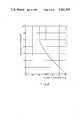
- FIG. 3is a graph illustrating the relationship between the viscosity and percentage change in flow rate at a constant pressure drop
- FIG. 4is a block diagram of the device according to the present invention.
- FIGS. 5a and 5billustrate examples of linear and rotary position transducers.
- FIGS. 1a, 1b, 1c and 1dtypical flow characteristic curves are shown for four different types of valves which clearly illustrate the variation between the flow characteristics of different valves and other types of valves can be treated in a similar way.
- the characteristic illustrated in FIG. 1ais for a Saunders Type "A" (Weir type) diaphragm valve and it can be seen that, for a 50% opening of the valve, the percentage flow through the valve would be of the order of approximately 65% whereas for a different type of diaphragm valve, namely a Saunders Type "KB" (straight through) diaphragm valve as illustrated in FIG.
- a similar percentage openingwould give a percentage flow through the valve of the order of 85%.
- a percentage opening of 50%would provide a 19% flow in the case of the butterfly valve and a 35% flow in the case of a ball valve. Consequently, the difficulties involved in providing a direct readout of the flow rate through a valve determined from the degree of opening of the valve can be clearly seen, in that it is a difficult matter to accommodate for such widely varying flow characteristics of different types of valves.
- the flow rate through a valveis determined by the viscosity of the fluid flowing through the valve and since viscosity varies with temperature, then the temperature of the fluid also has an effect on the flow rate, which introduces an additional variable which is again difficult to compensate for when attempting to provide an accurate indication of the flow rate through a valve.
- Typical viscosity/temperature curvesare illustrated in FIG. 2 for nine different types of fluid of varying viscosity as listed in the Table below:
- a further graph, illustrated in FIG. 3,illustrates the relationship between viscosity and percentage change in flow rate at constant pressure drop which can be assumed to be valid for all valve types, and which illustrates the direct viscosity has on flow rate.
- a position transducer 10which may be a rotary or a linear position transducer, is connected to a valve so that it is displaced with the valve actuator member, opening and closing the valve, so as to measure the valve stroke and to produce an electrical signal determined by the position of the valve actuator member.
- a suitable transducerwould be an analogue potentiometric division transducer and linear transducers are known having strokes of between 2.5 meters and 250 mm and a suitable transducer would be selected according to the stroke of the valve to be monitored.
- a rotary transducerfor valves utilising a rotary movement of the valve member rather than a linear displacement, a rotary transducer would be utilised, also in the form of a potentiometer the wiper of which is attached to the spindle of the valve member.
- FIGS. 5a and 5bExamples of suitable arrangements of transducers are illustrated in FIGS. 5a and 5b, 5a being a schematic illustration of a rotary type transducer and 5b illustrating a linear transducer.
- the transducer Tis potentiometer the wiper of which is displaceable with the valve actuator member of the valve to which it is connected, and two potentiometers A and B are provided to allow adjustment of the circuit to accommodate different transducers.
- a temperature stable resistance and Zener diode networkis provided to maintain stable potentials at the ends of the transducer, and the output voltage of the transducer T is buffered with a voltage follower to enable processor circuitry to be placed remotely from the valve up to a distance of 200 meters.
- the output of the voltage followeris supplied as an input to the analog-to-digital converter 12 of FIG. 4.
- the analog-to-digital converter 12converts the transducer output voltage to a digital signal for input to a microprocessor 13.
- the output of the analog-to-digital converter 12are supplied to the microprocessor 13 via a peripheral random access memory (RAM) and input-output device 15, the output data lines 14 of the analog-to-digital converter 12 being connected to a port A of the input-output device 15 and then provided as an input to the microprocessor 13 via data bus 16.
- Control of the analog-to-digital converter 12is performed by the microprocessor 13 by means of control lines 17 and 18.
- the peripheral RAM and input-output device 15has two further ports, port B and port C for driving the display 19 under the control of the microprocessor 13.
- Input of initial conditions governing the flow rateare provided by means of a key-pad 20 which enables an operator to identify to the processor the particular fluid flowing through a valve being monitored, to specify the type of valve and to input information such as the temperature and pressure of the fluid.
- Detailed information regarding the flow characteristics of the different types of valves to be monitored, together with information regarding the viscosity/temperature curves and the effect viscosity has on flow rate, such as illustrated in graphic form in FIGS. 1 to 3are stored as data in the program memory 21 which also contains the controlling program for the microprocessor 13.
- the program memory 21is suitably Erasable Programmable Read-Only Memory (EPROM) so that if necessary, the contents of the memory can be erased and a new program incorporated for the characteristics of a different family of valves or fluids.
- EPROMErasable Programmable Read-Only Memory
- appropriate meansmay be provided for inputting such information directly into the processor system from temperature probes 23 and pressure gauges 24, or even from flowmeters 25 for comparison purposes.
- the microprocessorcan be provided with suitable output control means 22 operating a servo-mechanism for automatically adjusting the valve to regulate the flow rate within prescribed tolerance limits, so as to enable the flow rate to be maintained independently of variations in pressure or temperature. Further, the microprocessor could annunciate an alarm if prescribed tolerance levels could not be maintained, or actuate other systems regulating the temperature and pressure of the fluid in a pipeline.
- the use of a microprocessorenables a large number of valves to be monitored simultaneously and an indication to be given of fluid flow through each valve for any number of fluid types including water at a specified temperature, preferably in the range 0° to 250° F., (-18° to 120° C.), and for the particular valve actuator position to be expressed as a percentage of the flow of water at 0° F. (-18° C.) through the same valve when fully open.
- the arrangement of the present inventionmay be a single integrated unit monitoring up to 250 valves simultaneously or it may be combined with a mini-computer with a visual display unit (VDU), or a main-frame computer and the output can be provided via the computer if required.
- VDUvisual display unit
- the microprocessor 13performs a series of calculations utilising the input data supplied via the keyboard or directly from in-line sensors, together with the information provided by the position transducer of the valve, and data stored in the memory 21 relating to the flow characteristic curves of each valve and the flow characteristics of the fluid flowing through the valve, to provide an output which is an indication of the flow rate through the valve derived directly from the position of the valve member. It is also possible to utilise the same information to ascertain the effect that variations of temperature or pressure will have on the flow through the valve.
- a devicewhich enables a plurality of valves to be simultaneously monitored and for the flow rate through valves to be ascertained in dependance upon the actual opening of the valve, and whilst the preferred embodiment relates particularly to valves, it should be readily apparent to a person skilled in the art that the device of the present invention is equally applicable with minor modification, relating to the type of transducer used, to pumps, for monitoring the flow therethrough.
Landscapes
- Physics & Mathematics (AREA)
- Fluid Mechanics (AREA)
- General Physics & Mathematics (AREA)
- Flow Control (AREA)
- Measuring Volume Flow (AREA)
- Control Of Positive-Displacement Pumps (AREA)
Abstract
Description
The present invention relates to a device for ascertaining the flow rate through at least one valve, which is capable of continuously monitoring and controlling the flow rate through several valves simultaneously.
At present, a range of mechanical, magnetic and electronic switches may be provided on or attachable to valves to provide an indication as to when a valve is fully open or fully closed, however, it has not been possible to accurately indicate intermediate positions of the valve stroke in a simple and economical way.
For instance, different types of valve have different flow characteristic curves relating percentage flow through the valve against percentage opening of the valve, so that even if the percentage opening of several different types of valve was the same, then widely differing flow rates result and thus make it extremely difficult for simple mechanical, magnetic and electronic devices, which measure the actual opening of the valve, to give a precise indication of the flow rate through the valve.
Further, for a given pressure and valve opening, changes in the temperature and viscosity of the fluid alter the flow performance which is difficult to compensate for with simple arrangements, and with very viscous fluids, if the temperature drops below a certain critical point, then viscosity may increase to an extent at which flow will cease altogether.
The aim of the present invention it to provide a device capable of ascertaining flow rate through at least one valve simultaneously and displaying said flow rate or utilising said flow rate to control said at least one valve.
According to the present invention a device for ascertaining flow rate through at least one valve comprises a transducer connectable to said at least one valve to be monitored, for providing a first signal representative of the position of the valve member of said at least one valve, electronic processing means receiving said first signal and having means enabling input of the information and/or further signals representing factors influencing the flow rate, said electronic processing means being capable of calculating flow rate through said at least one valve from said first signal and said input information and/or said further signals, the output of said electronic processing means being connected to a display means for displaying said calculated flow rate and/or to control means for adjusting said at least one valve to regulate the flow rate.
Preferably, the electronic processing means comprises a microprocessor programmed to calculate the flow rate through said at least one valve from equations representing the characteristic curve of said at least one valve which are stored in read-only memory (ROM) associated with the microprocessor. The various factors influencing the flow rate include the pressure drop across said at least one valve and the temperature of the fluid and these may be input to the microprocessor either via a keyboard or diectly from respective pressure and temperature sensing devices. A further factor influencing the flow rate is the viscosity of the fluid and information regarding the viscosity is input to the microprocessor via the keyboard as an initial condition when setting up. The input information can be displayed on the display means for an operator to check its accuracy prior to input of the information to the microprocessor to minimise the possibility of errors and additionally, with direct input of information relating to temperature and pressure, information regarding these values can be supplied by the microprocessor to the display to enable an operator to check that the temperature and pressure are at the required levels.
Since viscosity of the fluid varies with temperature, data regarding this variation for each type of fluid to be monitored is also stored in read-only memory associated with the microprocessor to enable the microprocessor to compensate for changes in viscosity due to variations in temperature.
The output of the microprocessor may additionally or alternatively be connected to means for controlling the position of the valve member of said at least one valve being monitored to enable the flow rate to be regulated or maintained, within prescribed tolerance levels from a desired value, independently of changes in pressure or temperature and/or to annunciate an alarm, if operational conditions cannot be maintained within prescribed tolerance levels.
The present invention will now be described further, by way of example, with reference to the accompanying drawings, in which:
FIGS. 1a, 1b, 1c and 1d illustrate typical flow characteristics of four different types of valve;
FIG. 2 is a series of graphs illustrating variations in viscosity of various fluids with respect to temperature;
FIG. 3 is a graph illustrating the relationship between the viscosity and percentage change in flow rate at a constant pressure drop;
FIG. 4 is a block diagram of the device according to the present invention; and
FIGS. 5a and 5b illustrate examples of linear and rotary position transducers.
Referring to the graphs shown in FIGS. 1a, 1b, 1c and 1d, typical flow characteristic curves are shown for four different types of valves which clearly illustrate the variation between the flow characteristics of different valves and other types of valves can be treated in a similar way. The characteristic illustrated in FIG. 1a is for a Saunders Type "A" (Weir type) diaphragm valve and it can be seen that, for a 50% opening of the valve, the percentage flow through the valve would be of the order of approximately 65% whereas for a different type of diaphragm valve, namely a Saunders Type "KB" (straight through) diaphragm valve as illustrated in FIG. 1b, a similar percentage opening would give a percentage flow through the valve of the order of 85%. For other types of valve, such as a ball valve, the characteristic of which is illustrated in FIG. 1c, and butterfly valve, a typical characteristic for which is illustrated in FIG. 1d, a percentage opening of 50% would provide a 19% flow in the case of the butterfly valve and a 35% flow in the case of a ball valve. Consequently, the difficulties involved in providing a direct readout of the flow rate through a valve determined from the degree of opening of the valve can be clearly seen, in that it is a difficult matter to accommodate for such widely varying flow characteristics of different types of valves.
In consequence, different techniques have so far only sought to indicate whether the valve was open or closed and the flow rate through the valve was hitherto determined using flowmeters.
Apart from variations in flow characteristics for different valve constructions, the flow rate through a valve is determined by the viscosity of the fluid flowing through the valve and since viscosity varies with temperature, then the temperature of the fluid also has an effect on the flow rate, which introduces an additional variable which is again difficult to compensate for when attempting to provide an accurate indication of the flow rate through a valve. Typical viscosity/temperature curves are illustrated in FIG. 2 for nine different types of fluid of varying viscosity as listed in the Table below:
______________________________________ TYPICAL VISCOSITY TEMP CURVES CURVE FLUID S.G. ______________________________________ 1 GAS OIL 0.85 2 HEAVY DIESEL FUEL 0.88 3 100SEC FUEL OIL 4 BRITOLUM 0.93 5 400 SEC FUEL OIL 0.95 6 900 SEC FUEL OIL 0.95 7 1400 SEC FUEL OIL 0.95 8 3500 SEC FUEL OIL 0.975 9 BUNKER "C" 0.99 ______________________________________
A further graph, illustrated in FIG. 3, illustrates the relationship between viscosity and percentage change in flow rate at constant pressure drop which can be assumed to be valid for all valve types, and which illustrates the direct viscosity has on flow rate.
In the device of the present invention, as illustrated in FIG. 4, aposition transducer 10, which may be a rotary or a linear position transducer, is connected to a valve so that it is displaced with the valve actuator member, opening and closing the valve, so as to measure the valve stroke and to produce an electrical signal determined by the position of the valve actuator member. A suitable transducer would be an analogue potentiometric division transducer and linear transducers are known having strokes of between 2.5 meters and 250 mm and a suitable transducer would be selected according to the stroke of the valve to be monitored. As an alternative to a linear transducer, for valves utilising a rotary movement of the valve member rather than a linear displacement, a rotary transducer would be utilised, also in the form of a potentiometer the wiper of which is attached to the spindle of the valve member.
Examples of suitable arrangements of transducers are illustrated in FIGS. 5a and 5b, 5a being a schematic illustration of a rotary type transducer and 5b illustrating a linear transducer. In each case the transducer T is potentiometer the wiper of which is displaceable with the valve actuator member of the valve to which it is connected, and two potentiometers A and B are provided to allow adjustment of the circuit to accommodate different transducers. A temperature stable resistance and Zener diode network is provided to maintain stable potentials at the ends of the transducer, and the output voltage of the transducer T is buffered with a voltage follower to enable processor circuitry to be placed remotely from the valve up to a distance of 200 meters. The output of the voltage follower is supplied as an input to the analog-to-digital converter 12 of FIG. 4. The analog-to-digital converter 12 converts the transducer output voltage to a digital signal for input to amicroprocessor 13. The output of the analog-to-digital converter 12 are supplied to themicroprocessor 13 via a peripheral random access memory (RAM) and input-output device 15, theoutput data lines 14 of the analog-to-digital converter 12 being connected to a port A of the input-output device 15 and then provided as an input to themicroprocessor 13 viadata bus 16. Control of the analog-to-digital converter 12 is performed by themicroprocessor 13 by means ofcontrol lines
The peripheral RAM and input-output device 15 has two further ports, port B and port C for driving the display 19 under the control of themicroprocessor 13. Input of initial conditions governing the flow rate are provided by means of a key-pad 20 which enables an operator to identify to the processor the particular fluid flowing through a valve being monitored, to specify the type of valve and to input information such as the temperature and pressure of the fluid. Detailed information regarding the flow characteristics of the different types of valves to be monitored, together with information regarding the viscosity/temperature curves and the effect viscosity has on flow rate, such as illustrated in graphic form in FIGS. 1 to 3 are stored as data in theprogram memory 21 which also contains the controlling program for themicroprocessor 13. Theprogram memory 21 is suitably Erasable Programmable Read-Only Memory (EPROM) so that if necessary, the contents of the memory can be erased and a new program incorporated for the characteristics of a different family of valves or fluids.
As an alternative to inputting information regarding the pressure and temperature via the keyboard, appropriate means may be provided for inputting such information directly into the processor system fromtemperature probes 23 andpressure gauges 24, or even fromflowmeters 25 for comparison purposes. Further, the microprocessor can be provided with suitable output control means 22 operating a servo-mechanism for automatically adjusting the valve to regulate the flow rate within prescribed tolerance limits, so as to enable the flow rate to be maintained independently of variations in pressure or temperature. Further, the microprocessor could annunciate an alarm if prescribed tolerance levels could not be maintained, or actuate other systems regulating the temperature and pressure of the fluid in a pipeline.
The use of a microprocessor enables a large number of valves to be monitored simultaneously and an indication to be given of fluid flow through each valve for any number of fluid types including water at a specified temperature, preferably in the range 0° to 250° F., (-18° to 120° C.), and for the particular valve actuator position to be expressed as a percentage of the flow of water at 0° F. (-18° C.) through the same valve when fully open. The arrangement of the present invention may be a single integrated unit monitoring up to 250 valves simultaneously or it may be combined with a mini-computer with a visual display unit (VDU), or a main-frame computer and the output can be provided via the computer if required.
In operation, themicroprocessor 13 performs a series of calculations utilising the input data supplied via the keyboard or directly from in-line sensors, together with the information provided by the position transducer of the valve, and data stored in thememory 21 relating to the flow characteristic curves of each valve and the flow characteristics of the fluid flowing through the valve, to provide an output which is an indication of the flow rate through the valve derived directly from the position of the valve member. It is also possible to utilise the same information to ascertain the effect that variations of temperature or pressure will have on the flow through the valve.
Thus, a device has been provided which enables a plurality of valves to be simultaneously monitored and for the flow rate through valves to be ascertained in dependance upon the actual opening of the valve, and whilst the preferred embodiment relates particularly to valves, it should be readily apparent to a person skilled in the art that the device of the present invention is equally applicable with minor modification, relating to the type of transducer used, to pumps, for monitoring the flow therethrough.
Claims (12)
1. A device for monitoring the flow rate through at least one valve to enable each said valve to be converted effectively into a flow meter, said device comprising a transducer connected to each said valve for providing a first signal representative of the position of the valve member of each said valve, electronic processing means which receives said first signal and having means enabling input of further signals representing static initial conditions and variable operating conditions influencing the flow rate, wherein said electronic processing means includes means enabling storage of data relating to the flow characteristic curves of a plurality of different types of valves, whereby said electronic processing means calculates the flow rate through each said valve from (a) said first signal, (b) the flow characteristics of said valve and (c) said further signals, said device further comprising display means connected to the output of said electronic processing means for displaying said calculated flow rate.
2. A device for monitoring the flow rate through at least one valve to enable each said valve to be converted effectively into a flow meter, said device comprising a transducer connected to each said valve for providing a first signal representative of the position of the valve member of each said valve, a electronic processing means which receives said first signal and having means enabling input of further signals representing static initial conditions and variable operating conditions influencing the flow rate, wherein said electronic processing means includes means enabling storage of data relating to the flow characteristic curves of a plurality of different types of valves, whereby said electronic processing means calculates the flow rate through each said valve from (a) said first signal, (b) the flow characteristics of said valve and (c) said further signals, said device further comprising control means connected to the output of said electronic processing means for adjusting each said valve to regulate the flow rate.
3. A device for monitoring the flow rate through at least one valve to enable each said valve to be converted effectively into a flowmeter, said device comprising a transducer connected to each said valve for providing a first signal representative of the position of the valve member of each said valve, electronic processing means which receives said first signal and having means enabling input of further signals representing static initial conditions and variable operating conditions influencing the flow rate, wherein said electronic processing means includes means enabling storage of data relating to the flow characteristic curves of a plurality of different types of valves, whereby said electronic processing means calculates the flow rate through each said valve from (a) said first signal, (b) the flow characteristics of said valve and (c) said further signals, said device further comprising display means connected to the output of said electronic processing means for displaying said calculated flow rate and control means connected to the output of said electronic processing means for adjusting each said valve to regulate the flow rate.
4. A device as claimed in claim 2 or 3, in which said control means activates a servo-mechanism connected to said valve to regulate the flow rate through said valve in accordance with programmed instructions and prevailing operating conditions.
5. A device as claimed in claim 1, 2 or 3, in which the electronic processing means monitors and controls up to 250 valves simultaneously in accordance with prescribed conditions.
6. A device as claimed in claim 1, 2 or 3, wherein the electronic processing means actuates an alarm if the flow rate ascertained falls outside a predetermined range of acceptable flow rate.
7. A device as claimed in claim 1, 2 or 3, wherein the electronic processing means predicts the effect of variations in temperature, pressure and valve opening on the flow rate.
8. A device as claimed in claim 1, 2 or 3, in which the transducer is connected to the electronic processing means via an analog-to-digital converter for converting the output of the transducer into digital form for input into the electronic processing means.
9. A device as claimed in claim 1, 2 or 3, wherein said electronic processing means is a microprocessor having storage means associated therewith containing data relating to the flow characteristics of a plurality of different types of valves and data regarding the effect of viscosity variations on flow rate and data relating to the variations in viscosity with temperature for a plurality of different fluids.
10. A device as claimed in claim 9, in which the transducer is connected to the electronic processing means via an analog-to-digital converter for converting the output of the transducer into digital form for input into the electronic processing means.
11. A device as claimed in claim 9, further comprising a key-board for enabling input of the static initial conditions to the microprocessor.
12. A device as claimed in claim 9, in which the variable operating conditions are supplied to the microprocessor from temperature and pressure sensors, and wherein calibration data is supplied to the microprocessor from flow meters.
Applications Claiming Priority (2)
| Application Number | Priority Date | Filing Date | Title |
|---|---|---|---|
| GB8017809AGB2077434B (en) | 1980-05-30 | 1980-05-30 | Ascertaining flow rate through valves or pumps |
| GB8017809 | 1980-05-30 |
Publications (1)
| Publication Number | Publication Date |
|---|---|
| US4581707Atrue US4581707A (en) | 1986-04-08 |
Family
ID=10513733
Family Applications (1)
| Application Number | Title | Priority Date | Filing Date |
|---|---|---|---|
| US06/346,068Expired - Fee RelatedUS4581707A (en) | 1980-05-30 | 1981-05-22 | Microprocessor controlled valve flow indicators |
Country Status (15)
| Country | Link |
|---|---|
| US (1) | US4581707A (en) |
| EP (1) | EP0052623B1 (en) |
| JP (1) | JPS57500710A (en) |
| AU (1) | AU568282B2 (en) |
| BE (1) | BE888985A (en) |
| CA (1) | CA1175530A (en) |
| DK (1) | DK7082A (en) |
| ES (1) | ES502504A0 (en) |
| GB (1) | GB2077434B (en) |
| HK (1) | HK100984A (en) |
| IE (1) | IE51205B1 (en) |
| IT (1) | IT1194972B (en) |
| MY (1) | MY8500853A (en) |
| SG (1) | SG64584G (en) |
| WO (1) | WO1981003542A1 (en) |
Cited By (87)
| Publication number | Priority date | Publication date | Assignee | Title |
|---|---|---|---|---|
| US4685066A (en)* | 1984-12-18 | 1987-08-04 | Caterpillar Inc. | Contamination monitor and method |
| US4725964A (en)* | 1984-01-31 | 1988-02-16 | Glaxo Group Limited | Computer controlled adapter unit for fluid system control |
| US4796651A (en)* | 1988-03-30 | 1989-01-10 | LeRoy D. Ginn | Variable gas volume flow measuring and control methods and apparatus |
| US4799169A (en)* | 1987-05-26 | 1989-01-17 | Mark Industries, Inc. | Gas well flow instrumentation |
| US4805118A (en)* | 1987-02-04 | 1989-02-14 | Systecon, Inc. | Monitor and control for a multi-pump system |
| US4807150A (en)* | 1986-10-02 | 1989-02-21 | Phillips Petroleum Company | Constraint control for a compressor system |
| US4888706A (en)* | 1982-07-06 | 1989-12-19 | Institute Of Gas Technology | Fluid distribution to multiple users through distributed intelligence sub-centers |
| US4945491A (en)* | 1987-02-04 | 1990-07-31 | Systecon, Inc. | Monitor and control for a multi-pump system |
| US4951224A (en)* | 1987-07-30 | 1990-08-21 | Jiri Hokynar | Control device for fluid flow |
| US4979641A (en)* | 1987-08-19 | 1990-12-25 | Turner Charles S | Computerized beer dispensing system |
| US5032992A (en)* | 1986-07-23 | 1991-07-16 | American Standard Inc. | Electronic temperature control system |
| US5067094A (en)* | 1989-04-13 | 1991-11-19 | Combustion Engineering, Inc. | Quantifying isolation valve leakage |
| US5107441A (en)* | 1990-10-31 | 1992-04-21 | Otis Engineering Corporation | System for evaluating the flow performance characteristics of a device |
| US5148841A (en)* | 1989-06-27 | 1992-09-22 | Serac Group | Filling apparatus for filling receptacle with metered weights |
| DE4207144A1 (en)* | 1992-03-06 | 1993-09-09 | Bayer Ag | METHOD FOR REGULATING HEAT EXCHANGERS |
| US5251148A (en)* | 1990-06-01 | 1993-10-05 | Valtek, Inc. | Integrated process control valve |
| US5320760A (en)* | 1992-12-07 | 1994-06-14 | E. I. Du Pont De Nemours And Company | Method of determining filter pluggage by measuring pressures |
| US5321601A (en)* | 1992-02-28 | 1994-06-14 | Riedel Dennis S | Apparatus for controlling flow in a sewer regulator |
| US5329465A (en)* | 1987-10-30 | 1994-07-12 | Westinghouse Electric Corp. | Online valve diagnostic monitoring system |
| DE4326343A1 (en)* | 1993-08-05 | 1995-02-09 | Honeywell Ag | Diganose system for control and shut-off valves |
| US5526674A (en)* | 1992-04-30 | 1996-06-18 | Sierra Instruments, Inc. | Method and apparatus for improved flow rate measurement and calibration |
| DE29606674U1 (en)* | 1996-04-12 | 1996-08-22 | E. Wehrle GmbH, 78120 Furtwangen | Combined cold and hot water meter |
| FR2746913A1 (en)* | 1996-03-28 | 1997-10-03 | Samson Ag | METHOD AND DEVICE FOR DETERMINING THE FLOW OF A PROCESS FLUID AT A REGULATORY APPARATUS |
| DE29719163U1 (en) | 1997-10-29 | 1998-02-19 | Fischer Gase GmbH, 74927 Eschelbronn | Measuring device for fire water pipes |
| US5902927A (en)* | 1995-12-01 | 1999-05-11 | Perception Incorporated | Fluid metering apparatus and method |
| US6076542A (en)* | 1995-12-01 | 2000-06-20 | Perception Incorporated | Fluid metering method |
| US20010054967A1 (en)* | 2000-06-23 | 2001-12-27 | Vanderah Richard J. | Low power regulator system and method |
| US6539315B1 (en) | 1999-06-29 | 2003-03-25 | Fisher Controls International, Inc. | Regulator flow measurement apparatus |
| US6542827B1 (en) | 2000-08-31 | 2003-04-01 | Wallace C. Koster | Well tending method and apparatus |
| US20030233203A1 (en)* | 1999-06-29 | 2003-12-18 | Grumstrup Bruce F. | Regulator flow measurement apparatus |
| US6704682B2 (en)* | 2001-07-09 | 2004-03-09 | Angela E. Summers | Dual sensor process pressure switch having high-diagnostic one-out-of-two voting architecture |
| US6725167B2 (en) | 2002-01-16 | 2004-04-20 | Fisher Controls International Llc | Flow measurement module and method |
| US20050017736A1 (en)* | 2001-11-02 | 2005-01-27 | Siemens Aktiengesellschaft | Measuring transducer |
| US20050273204A1 (en)* | 2000-02-14 | 2005-12-08 | Invensys Systems, Inc., A Massachusetts Corporation | Intelligent valve flow linearization |
| US20060117477A1 (en)* | 2004-12-03 | 2006-06-08 | Rosko M S | Sprayer with non-faucet control |
| US20060172442A1 (en)* | 2003-07-16 | 2006-08-03 | Tsuneyuki Okabe | Semiconductor production system and semiconductor production process |
| US20060231637A1 (en)* | 2005-04-19 | 2006-10-19 | Schmitt Randall P | Fluid mixer |
| US20060231636A1 (en)* | 2005-04-19 | 2006-10-19 | Schmitt Randall P | Fluid mixer |
| US20070144485A1 (en)* | 2005-11-18 | 2007-06-28 | Matthew Snow | Water/Alcohol Injection Flow Switch Safety Device |
| US20070157978A1 (en)* | 2004-01-12 | 2007-07-12 | Jonte Patrick B | Multi-mode hands free automatic faucet |
| US20070246267A1 (en)* | 2006-04-20 | 2007-10-25 | Koottungal Paul D | Touch sensor |
| US20070246550A1 (en)* | 2006-04-20 | 2007-10-25 | Rodenbeck Robert W | Electronic user interface for electronic mixing of water for residential faucets |
| US20070246564A1 (en)* | 2006-04-20 | 2007-10-25 | Masco Corporation Of Indiana | Pull-out wand |
| US20080105764A1 (en)* | 2006-10-25 | 2008-05-08 | Yan Jianglin | Faucet spray head |
| US7458520B2 (en) | 2005-04-19 | 2008-12-02 | Masco Corporation Of Indiana | Electronic proportioning valve |
| US7584898B2 (en) | 2005-07-01 | 2009-09-08 | Masco Corporation Of Indiana | Manual override for electronic proportioning valve |
| US20090320478A1 (en)* | 2006-01-04 | 2009-12-31 | General Electric Company | Reduced boundary layer separation steam jet air ejector assembly and method |
| US20100044604A1 (en)* | 2007-03-28 | 2010-02-25 | Masco Corporation Of Indiana | Capacitive touch sensor |
| US7871020B2 (en) | 2006-01-26 | 2011-01-18 | Masco Corporation Of Indiana | Faucet spray head with volume control |
| US20110088784A1 (en)* | 2009-10-19 | 2011-04-21 | Steven Kyle Meehan | Multi-function pull-out wand |
| US8365767B2 (en) | 2006-04-20 | 2013-02-05 | Masco Corporation Of Indiana | User interface for a faucet |
| US8424781B2 (en) | 2006-02-06 | 2013-04-23 | Masco Corporation Of Indiana | Power sprayer |
| US20130153062A1 (en)* | 2011-12-15 | 2013-06-20 | Honeywell International Inc. | Gas valve with fuel rate monitor |
| US8469056B2 (en) | 2007-01-31 | 2013-06-25 | Masco Corporation Of Indiana | Mixing valve including a molded waterway assembly |
| US8561626B2 (en) | 2010-04-20 | 2013-10-22 | Masco Corporation Of Indiana | Capacitive sensing system and method for operating a faucet |
| US8613419B2 (en) | 2007-12-11 | 2013-12-24 | Masco Corporation Of Indiana | Capacitive coupling arrangement for a faucet |
| US8776817B2 (en) | 2010-04-20 | 2014-07-15 | Masco Corporation Of Indiana | Electronic faucet with a capacitive sensing system and a method therefor |
| US20140261714A1 (en)* | 2013-03-15 | 2014-09-18 | Schneider Electric Buildings, Llc | Advanced Valve Actuator With True Flow Feedback |
| US8839815B2 (en) | 2011-12-15 | 2014-09-23 | Honeywell International Inc. | Gas valve with electronic cycle counter |
| US8899264B2 (en) | 2011-12-15 | 2014-12-02 | Honeywell International Inc. | Gas valve with electronic proof of closure system |
| US8944105B2 (en) | 2007-01-31 | 2015-02-03 | Masco Corporation Of Indiana | Capacitive sensing apparatus and method for faucets |
| US8947242B2 (en) | 2011-12-15 | 2015-02-03 | Honeywell International Inc. | Gas valve with valve leakage test |
| US9074770B2 (en) | 2011-12-15 | 2015-07-07 | Honeywell International Inc. | Gas valve with electronic valve proving system |
| US9175458B2 (en) | 2012-04-20 | 2015-11-03 | Delta Faucet Company | Faucet including a pullout wand with a capacitive sensing |
| US9234661B2 (en) | 2012-09-15 | 2016-01-12 | Honeywell International Inc. | Burner control system |
| US9243756B2 (en) | 2006-04-20 | 2016-01-26 | Delta Faucet Company | Capacitive user interface for a faucet and method of forming |
| US9243392B2 (en) | 2006-12-19 | 2016-01-26 | Delta Faucet Company | Resistive coupling for an automatic faucet |
| US20160255859A1 (en)* | 2015-03-04 | 2016-09-08 | Mark Salerno | Method and apparatus for monitoring the dispensing of a soft serve product |
| US9557059B2 (en) | 2011-12-15 | 2017-01-31 | Honeywell International Inc | Gas valve with communication link |
| US9645584B2 (en) | 2014-09-17 | 2017-05-09 | Honeywell International Inc. | Gas valve with electronic health monitoring |
| US20170138154A1 (en)* | 2003-01-10 | 2017-05-18 | Woodward, Inc. | Wireless Control Valve |
| US9683674B2 (en) | 2013-10-29 | 2017-06-20 | Honeywell Technologies Sarl | Regulating device |
| US9835265B2 (en) | 2011-12-15 | 2017-12-05 | Honeywell International Inc. | Valve with actuator diagnostics |
| US9841122B2 (en) | 2014-09-09 | 2017-12-12 | Honeywell International Inc. | Gas valve with electronic valve proving system |
| US9846440B2 (en) | 2011-12-15 | 2017-12-19 | Honeywell International Inc. | Valve controller configured to estimate fuel comsumption |
| US9851103B2 (en) | 2011-12-15 | 2017-12-26 | Honeywell International Inc. | Gas valve with overpressure diagnostics |
| US9995486B2 (en) | 2011-12-15 | 2018-06-12 | Honeywell International Inc. | Gas valve with high/low gas pressure detection |
| US10024439B2 (en) | 2013-12-16 | 2018-07-17 | Honeywell International Inc. | Valve over-travel mechanism |
| US10422531B2 (en) | 2012-09-15 | 2019-09-24 | Honeywell International Inc. | System and approach for controlling a combustion chamber |
| US10503181B2 (en) | 2016-01-13 | 2019-12-10 | Honeywell International Inc. | Pressure regulator |
| US10528065B1 (en)* | 2017-08-24 | 2020-01-07 | Samir Alexander Sidhom | Automated fluid flow control system with accelerated speed of response |
| US10564062B2 (en) | 2016-10-19 | 2020-02-18 | Honeywell International Inc. | Human-machine interface for gas valve |
| US10697815B2 (en) | 2018-06-09 | 2020-06-30 | Honeywell International Inc. | System and methods for mitigating condensation in a sensor module |
| US11035368B2 (en) | 2016-05-31 | 2021-06-15 | Fluid Handling Llc | Pump control design toolbox technique for variable speed pumping applications |
| US11073281B2 (en) | 2017-12-29 | 2021-07-27 | Honeywell International Inc. | Closed-loop programming and control of a combustion appliance |
| US11267003B2 (en) | 2005-05-13 | 2022-03-08 | Delta Faucet Company | Power sprayer |
| CN119914741A (en)* | 2025-04-03 | 2025-05-02 | 四川锦宇装备有限公司 | A control method and circuit adapted to different valve openings of steam regulating valves |
Families Citing this family (8)
| Publication number | Priority date | Publication date | Assignee | Title |
|---|---|---|---|---|
| CA1294345C (en)* | 1985-11-26 | 1992-01-14 | Kevin D. Thompson | Electronic controlled gas valve and method |
| GB8711369D0 (en)* | 1987-05-14 | 1987-06-17 | Nomix Mfg Co Ltd | Electronic pump control |
| US5182951A (en)* | 1988-01-27 | 1993-02-02 | Jorritsma Johannes N | Method and aparatus for calculating flow rates through a pumping station |
| JP2574449B2 (en)* | 1989-02-17 | 1997-01-22 | 株式会社巴技術研究所 | Butterfly valve |
| CA2089328A1 (en)* | 1993-02-11 | 1994-08-12 | John Zegray | Oil consumption meter |
| CN1093612A (en)* | 1993-11-12 | 1994-10-19 | 徐兆火 | Intelligent all-round control circuit device for drinking water treatment machine |
| WO2000032314A1 (en)* | 1998-12-01 | 2000-06-08 | American Standard International, Inc. | Control interface for electronic fluid control valve |
| FR2859018B1 (en)* | 2003-08-22 | 2005-10-07 | Snecma Moteurs | DEVICE FOR ESTIMATING MASS FLOW OF FUEL |
Citations (10)
| Publication number | Priority date | Publication date | Assignee | Title |
|---|---|---|---|---|
| US29383A (en)* | 1860-07-31 | Improvement in preserving food | ||
| US3701280A (en)* | 1970-03-18 | 1972-10-31 | Daniel Ind Inc | Method and apparatus for determining the supercompressibility factor of natural gas |
| US3729995A (en)* | 1971-08-26 | 1973-05-01 | Fischer & Porter Co | Pressure and temperature compensation system for flowmeter |
| US3871214A (en)* | 1972-10-06 | 1975-03-18 | Nissan Motor | Electronic engine intake air flow measuring device |
| US3875955A (en)* | 1974-01-10 | 1975-04-08 | Process Systems | Digital fluid flow rate measurement or control system |
| US3888458A (en)* | 1972-08-09 | 1975-06-10 | Gen Motors Corp | Mass flow air meter |
| USRE29383E (en) | 1974-01-10 | 1977-09-06 | Process Systems, Inc. | Digital fluid flow rate measurement or control system |
| US4108574A (en)* | 1977-01-21 | 1978-08-22 | International Paper Company | Apparatus and method for the indirect measurement and control of the flow rate of a liquid in a piping system |
| US4149254A (en)* | 1975-06-25 | 1979-04-10 | American Chain & Cable Co., Inc. | Method and apparatus for flow metering |
| GB2026704A (en)* | 1978-07-27 | 1980-02-06 | Alsthom Atlantique | Device for Measuring Fluid Flow in Tubing |
Family Cites Families (4)
| Publication number | Priority date | Publication date | Assignee | Title |
|---|---|---|---|---|
| DE1423906A1 (en)* | 1961-12-08 | 1969-01-30 | Siemens Ag | Flow control device |
| JPS5027614A (en)* | 1973-07-17 | 1975-03-20 | ||
| JPS5335888A (en)* | 1976-09-16 | 1978-04-03 | Hitachi Ltd | Flow control valve control system |
| JPS5528108A (en)* | 1978-08-16 | 1980-02-28 | Hitachi Ltd | Control system for constant flow for series power generating station |
- 1980
- 1980-05-30GBGB8017809Apatent/GB2077434B/ennot_activeExpired
- 1981
- 1981-05-22AUAU71724/81Apatent/AU568282B2/ennot_activeCeased
- 1981-05-22USUS06/346,068patent/US4581707A/ennot_activeExpired - Fee Related
- 1981-05-22EPEP81901303Apatent/EP0052623B1/ennot_activeExpired
- 1981-05-22WOPCT/GB1981/000092patent/WO1981003542A1/enactiveIP Right Grant
- 1981-05-22JPJP56501669Apatent/JPS57500710A/jaactivePending
- 1981-05-26BEBE6/47461Apatent/BE888985A/ennot_activeIP Right Cessation
- 1981-05-26ESES502504Apatent/ES502504A0/enactiveGranted
- 1981-05-28ITIT05165/81Apatent/IT1194972B/enactive
- 1981-05-29IEIE1199/81Apatent/IE51205B1/enunknown
- 1981-05-29CACA000378607Apatent/CA1175530A/ennot_activeExpired
- 1982
- 1982-01-11DKDK7082Apatent/DK7082A/ennot_activeApplication Discontinuation
- 1984
- 1984-09-07SGSG645/84Apatent/SG64584G/enunknown
- 1984-12-27HKHK1009/84Apatent/HK100984A/enunknown
- 1985
- 1985-12-30MYMY853/85Apatent/MY8500853A/enunknown
Patent Citations (11)
| Publication number | Priority date | Publication date | Assignee | Title |
|---|---|---|---|---|
| US29383A (en)* | 1860-07-31 | Improvement in preserving food | ||
| US3701280A (en)* | 1970-03-18 | 1972-10-31 | Daniel Ind Inc | Method and apparatus for determining the supercompressibility factor of natural gas |
| US3729995A (en)* | 1971-08-26 | 1973-05-01 | Fischer & Porter Co | Pressure and temperature compensation system for flowmeter |
| US3888458A (en)* | 1972-08-09 | 1975-06-10 | Gen Motors Corp | Mass flow air meter |
| US3871214A (en)* | 1972-10-06 | 1975-03-18 | Nissan Motor | Electronic engine intake air flow measuring device |
| US3875955A (en)* | 1974-01-10 | 1975-04-08 | Process Systems | Digital fluid flow rate measurement or control system |
| GB1476831A (en)* | 1974-01-10 | 1977-06-16 | Process Systems | Digital fluid flow rate measurement or control system |
| USRE29383E (en) | 1974-01-10 | 1977-09-06 | Process Systems, Inc. | Digital fluid flow rate measurement or control system |
| US4149254A (en)* | 1975-06-25 | 1979-04-10 | American Chain & Cable Co., Inc. | Method and apparatus for flow metering |
| US4108574A (en)* | 1977-01-21 | 1978-08-22 | International Paper Company | Apparatus and method for the indirect measurement and control of the flow rate of a liquid in a piping system |
| GB2026704A (en)* | 1978-07-27 | 1980-02-06 | Alsthom Atlantique | Device for Measuring Fluid Flow in Tubing |
Cited By (132)
| Publication number | Priority date | Publication date | Assignee | Title |
|---|---|---|---|---|
| US4888706A (en)* | 1982-07-06 | 1989-12-19 | Institute Of Gas Technology | Fluid distribution to multiple users through distributed intelligence sub-centers |
| US4725964A (en)* | 1984-01-31 | 1988-02-16 | Glaxo Group Limited | Computer controlled adapter unit for fluid system control |
| US4685066A (en)* | 1984-12-18 | 1987-08-04 | Caterpillar Inc. | Contamination monitor and method |
| US5032992A (en)* | 1986-07-23 | 1991-07-16 | American Standard Inc. | Electronic temperature control system |
| US4807150A (en)* | 1986-10-02 | 1989-02-21 | Phillips Petroleum Company | Constraint control for a compressor system |
| US4805118A (en)* | 1987-02-04 | 1989-02-14 | Systecon, Inc. | Monitor and control for a multi-pump system |
| US4945491A (en)* | 1987-02-04 | 1990-07-31 | Systecon, Inc. | Monitor and control for a multi-pump system |
| US4799169A (en)* | 1987-05-26 | 1989-01-17 | Mark Industries, Inc. | Gas well flow instrumentation |
| US4951224A (en)* | 1987-07-30 | 1990-08-21 | Jiri Hokynar | Control device for fluid flow |
| US4979641A (en)* | 1987-08-19 | 1990-12-25 | Turner Charles S | Computerized beer dispensing system |
| US5329465A (en)* | 1987-10-30 | 1994-07-12 | Westinghouse Electric Corp. | Online valve diagnostic monitoring system |
| US4796651A (en)* | 1988-03-30 | 1989-01-10 | LeRoy D. Ginn | Variable gas volume flow measuring and control methods and apparatus |
| US5067094A (en)* | 1989-04-13 | 1991-11-19 | Combustion Engineering, Inc. | Quantifying isolation valve leakage |
| US5148841A (en)* | 1989-06-27 | 1992-09-22 | Serac Group | Filling apparatus for filling receptacle with metered weights |
| US5251148A (en)* | 1990-06-01 | 1993-10-05 | Valtek, Inc. | Integrated process control valve |
| US5107441A (en)* | 1990-10-31 | 1992-04-21 | Otis Engineering Corporation | System for evaluating the flow performance characteristics of a device |
| US5321601A (en)* | 1992-02-28 | 1994-06-14 | Riedel Dennis S | Apparatus for controlling flow in a sewer regulator |
| DE4207144A1 (en)* | 1992-03-06 | 1993-09-09 | Bayer Ag | METHOD FOR REGULATING HEAT EXCHANGERS |
| US5684246A (en)* | 1992-04-30 | 1997-11-04 | Sierra Instruments, Inc. | Method and apparatus for improved flow rate measurement and calibration |
| US5526674A (en)* | 1992-04-30 | 1996-06-18 | Sierra Instruments, Inc. | Method and apparatus for improved flow rate measurement and calibration |
| US5320760A (en)* | 1992-12-07 | 1994-06-14 | E. I. Du Pont De Nemours And Company | Method of determining filter pluggage by measuring pressures |
| DE4326343A1 (en)* | 1993-08-05 | 1995-02-09 | Honeywell Ag | Diganose system for control and shut-off valves |
| US6460565B1 (en) | 1995-12-01 | 2002-10-08 | Perception Incorporated | Fluid metering apparatus and method |
| US5902927A (en)* | 1995-12-01 | 1999-05-11 | Perception Incorporated | Fluid metering apparatus and method |
| US6076542A (en)* | 1995-12-01 | 2000-06-20 | Perception Incorporated | Fluid metering method |
| US6202679B1 (en) | 1995-12-01 | 2001-03-20 | Perception Incorporated | Fluid metering apparatus |
| FR2746913A1 (en)* | 1996-03-28 | 1997-10-03 | Samson Ag | METHOD AND DEVICE FOR DETERMINING THE FLOW OF A PROCESS FLUID AT A REGULATORY APPARATUS |
| DE29606674U1 (en)* | 1996-04-12 | 1996-08-22 | E. Wehrle GmbH, 78120 Furtwangen | Combined cold and hot water meter |
| DE29719163U1 (en) | 1997-10-29 | 1998-02-19 | Fischer Gase GmbH, 74927 Eschelbronn | Measuring device for fire water pipes |
| US20030233203A1 (en)* | 1999-06-29 | 2003-12-18 | Grumstrup Bruce F. | Regulator flow measurement apparatus |
| US6539315B1 (en) | 1999-06-29 | 2003-03-25 | Fisher Controls International, Inc. | Regulator flow measurement apparatus |
| US20040078117A1 (en)* | 1999-06-29 | 2004-04-22 | Fisher Controls International Llc | Low power regulator system and method |
| US6895351B2 (en) | 1999-06-29 | 2005-05-17 | Fisher Controls International Llc | Regulator flow measurement apparatus |
| US6903659B2 (en) | 1999-06-29 | 2005-06-07 | Fisher Controls International Llc. | Low power regulator system and method |
| US20050273204A1 (en)* | 2000-02-14 | 2005-12-08 | Invensys Systems, Inc., A Massachusetts Corporation | Intelligent valve flow linearization |
| US7266427B2 (en) | 2000-02-14 | 2007-09-04 | Invensys Systems, Inc. | Intelligent valve flow linearization |
| US7096093B1 (en)* | 2000-02-14 | 2006-08-22 | Invensys Systems, Inc. | Intelligent valve flow linearization |
| US20010054967A1 (en)* | 2000-06-23 | 2001-12-27 | Vanderah Richard J. | Low power regulator system and method |
| US7064671B2 (en) | 2000-06-23 | 2006-06-20 | Fisher Controls International Llc | Low power regulator system and method |
| US6542827B1 (en) | 2000-08-31 | 2003-04-01 | Wallace C. Koster | Well tending method and apparatus |
| US6704682B2 (en)* | 2001-07-09 | 2004-03-09 | Angela E. Summers | Dual sensor process pressure switch having high-diagnostic one-out-of-two voting architecture |
| US20050017736A1 (en)* | 2001-11-02 | 2005-01-27 | Siemens Aktiengesellschaft | Measuring transducer |
| US7054765B2 (en)* | 2001-11-02 | 2006-05-30 | Siemens Aktiengesellschaft | Measuring transducer |
| US6725167B2 (en) | 2002-01-16 | 2004-04-20 | Fisher Controls International Llc | Flow measurement module and method |
| US20170138154A1 (en)* | 2003-01-10 | 2017-05-18 | Woodward, Inc. | Wireless Control Valve |
| US7510884B2 (en)* | 2003-07-16 | 2009-03-31 | Tokyo Electron Limited | Semiconductor production system and semiconductor production process |
| US20060172442A1 (en)* | 2003-07-16 | 2006-08-03 | Tsuneyuki Okabe | Semiconductor production system and semiconductor production process |
| US9243391B2 (en) | 2004-01-12 | 2016-01-26 | Delta Faucet Company | Multi-mode hands free automatic faucet |
| US8528579B2 (en) | 2004-01-12 | 2013-09-10 | Masco Corporation Of Indiana | Multi-mode hands free automatic faucet |
| US20100096017A1 (en)* | 2004-01-12 | 2010-04-22 | Masco Corporation Of Indiana | Multi-mode hands free automatic faucet |
| US7690395B2 (en) | 2004-01-12 | 2010-04-06 | Masco Corporation Of Indiana | Multi-mode hands free automatic faucet |
| US20070157978A1 (en)* | 2004-01-12 | 2007-07-12 | Jonte Patrick B | Multi-mode hands free automatic faucet |
| US20060117477A1 (en)* | 2004-12-03 | 2006-06-08 | Rosko M S | Sprayer with non-faucet control |
| US7343930B2 (en) | 2004-12-03 | 2008-03-18 | Masco Corporation Of Indiana | Sprayer with non-faucet control |
| US7458520B2 (en) | 2005-04-19 | 2008-12-02 | Masco Corporation Of Indiana | Electronic proportioning valve |
| US7448553B2 (en) | 2005-04-19 | 2008-11-11 | Masco Corporation Of Indiana | Fluid mixer |
| US20060231637A1 (en)* | 2005-04-19 | 2006-10-19 | Schmitt Randall P | Fluid mixer |
| US7475827B2 (en) | 2005-04-19 | 2009-01-13 | Masco Corporation Of Indiana | Fluid mixer |
| US20060231636A1 (en)* | 2005-04-19 | 2006-10-19 | Schmitt Randall P | Fluid mixer |
| US11267003B2 (en) | 2005-05-13 | 2022-03-08 | Delta Faucet Company | Power sprayer |
| US7584898B2 (en) | 2005-07-01 | 2009-09-08 | Masco Corporation Of Indiana | Manual override for electronic proportioning valve |
| US7581516B2 (en)* | 2005-11-18 | 2009-09-01 | Matthew Snow | Water/alcohol injection flow switch safety device |
| US20070144485A1 (en)* | 2005-11-18 | 2007-06-28 | Matthew Snow | Water/Alcohol Injection Flow Switch Safety Device |
| US20090320478A1 (en)* | 2006-01-04 | 2009-12-31 | General Electric Company | Reduced boundary layer separation steam jet air ejector assembly and method |
| US7871020B2 (en) | 2006-01-26 | 2011-01-18 | Masco Corporation Of Indiana | Faucet spray head with volume control |
| US8424781B2 (en) | 2006-02-06 | 2013-04-23 | Masco Corporation Of Indiana | Power sprayer |
| US9715238B2 (en) | 2006-04-20 | 2017-07-25 | Delta Faucet Company | Electronic user interface for electronic mixing of water for residential faucets |
| US9285807B2 (en) | 2006-04-20 | 2016-03-15 | Delta Faucet Company | Electronic user interface for electronic mixing of water for residential faucets |
| US8089473B2 (en) | 2006-04-20 | 2012-01-03 | Masco Corporation Of Indiana | Touch sensor |
| US8118240B2 (en) | 2006-04-20 | 2012-02-21 | Masco Corporation Of Indiana | Pull-out wand |
| US9243756B2 (en) | 2006-04-20 | 2016-01-26 | Delta Faucet Company | Capacitive user interface for a faucet and method of forming |
| US20070246564A1 (en)* | 2006-04-20 | 2007-10-25 | Masco Corporation Of Indiana | Pull-out wand |
| US8162236B2 (en) | 2006-04-20 | 2012-04-24 | Masco Corporation Of Indiana | Electronic user interface for electronic mixing of water for residential faucets |
| US8243040B2 (en) | 2006-04-20 | 2012-08-14 | Masco Corporation Of Indiana | Touch sensor |
| US8365767B2 (en) | 2006-04-20 | 2013-02-05 | Masco Corporation Of Indiana | User interface for a faucet |
| US20070246550A1 (en)* | 2006-04-20 | 2007-10-25 | Rodenbeck Robert W | Electronic user interface for electronic mixing of water for residential faucets |
| US9228329B2 (en) | 2006-04-20 | 2016-01-05 | Delta Faucet Company | Pull-out wand |
| US20070246267A1 (en)* | 2006-04-20 | 2007-10-25 | Koottungal Paul D | Touch sensor |
| US11886208B2 (en) | 2006-04-20 | 2024-01-30 | Delta Faucet Company | Electronic user interface for electronic mixing of water for residential faucets |
| US9856634B2 (en) | 2006-04-20 | 2018-01-02 | Delta Faucet Company | Fluid delivery device with an in-water capacitive sensor |
| US10698429B2 (en) | 2006-04-20 | 2020-06-30 | Delta Faucet Company | Electronic user interface for electronic mixing of water for residential faucets |
| US20080105764A1 (en)* | 2006-10-25 | 2008-05-08 | Yan Jianglin | Faucet spray head |
| US8152078B2 (en) | 2006-10-25 | 2012-04-10 | Masco Corporation Of Indiana | Faucet spray head |
| US9243392B2 (en) | 2006-12-19 | 2016-01-26 | Delta Faucet Company | Resistive coupling for an automatic faucet |
| US20100012194A1 (en)* | 2006-12-19 | 2010-01-21 | Jonte Patrick B | Multi-mode hands free automatic faucet |
| US8844564B2 (en) | 2006-12-19 | 2014-09-30 | Masco Corporation Of Indiana | Multi-mode hands free automatic faucet |
| US8127782B2 (en) | 2006-12-19 | 2012-03-06 | Jonte Patrick B | Multi-mode hands free automatic faucet |
| US8469056B2 (en) | 2007-01-31 | 2013-06-25 | Masco Corporation Of Indiana | Mixing valve including a molded waterway assembly |
| US8944105B2 (en) | 2007-01-31 | 2015-02-03 | Masco Corporation Of Indiana | Capacitive sensing apparatus and method for faucets |
| US20100044604A1 (en)* | 2007-03-28 | 2010-02-25 | Masco Corporation Of Indiana | Capacitive touch sensor |
| US8376313B2 (en) | 2007-03-28 | 2013-02-19 | Masco Corporation Of Indiana | Capacitive touch sensor |
| US8613419B2 (en) | 2007-12-11 | 2013-12-24 | Masco Corporation Of Indiana | Capacitive coupling arrangement for a faucet |
| US9315976B2 (en) | 2007-12-11 | 2016-04-19 | Delta Faucet Company | Capacitive coupling arrangement for a faucet |
| US20110088784A1 (en)* | 2009-10-19 | 2011-04-21 | Steven Kyle Meehan | Multi-function pull-out wand |
| US8448667B2 (en) | 2009-10-19 | 2013-05-28 | Masco Corporation Of Indiana | Multi-function pull-out wand |
| US8561626B2 (en) | 2010-04-20 | 2013-10-22 | Masco Corporation Of Indiana | Capacitive sensing system and method for operating a faucet |
| US8776817B2 (en) | 2010-04-20 | 2014-07-15 | Masco Corporation Of Indiana | Electronic faucet with a capacitive sensing system and a method therefor |
| US9394675B2 (en) | 2010-04-20 | 2016-07-19 | Delta Faucet Company | Capacitive sensing system and method for operating a faucet |
| US9851103B2 (en) | 2011-12-15 | 2017-12-26 | Honeywell International Inc. | Gas valve with overpressure diagnostics |
| US9846440B2 (en) | 2011-12-15 | 2017-12-19 | Honeywell International Inc. | Valve controller configured to estimate fuel comsumption |
| US8899264B2 (en) | 2011-12-15 | 2014-12-02 | Honeywell International Inc. | Gas valve with electronic proof of closure system |
| US9074770B2 (en) | 2011-12-15 | 2015-07-07 | Honeywell International Inc. | Gas valve with electronic valve proving system |
| US9557059B2 (en) | 2011-12-15 | 2017-01-31 | Honeywell International Inc | Gas valve with communication link |
| US20130153062A1 (en)* | 2011-12-15 | 2013-06-20 | Honeywell International Inc. | Gas valve with fuel rate monitor |
| US10697632B2 (en) | 2011-12-15 | 2020-06-30 | Honeywell International Inc. | Gas valve with communication link |
| US10851993B2 (en) | 2011-12-15 | 2020-12-01 | Honeywell International Inc. | Gas valve with overpressure diagnostics |
| US9995486B2 (en) | 2011-12-15 | 2018-06-12 | Honeywell International Inc. | Gas valve with high/low gas pressure detection |
| US8839815B2 (en) | 2011-12-15 | 2014-09-23 | Honeywell International Inc. | Gas valve with electronic cycle counter |
| US8905063B2 (en)* | 2011-12-15 | 2014-12-09 | Honeywell International Inc. | Gas valve with fuel rate monitor |
| US9835265B2 (en) | 2011-12-15 | 2017-12-05 | Honeywell International Inc. | Valve with actuator diagnostics |
| US8947242B2 (en) | 2011-12-15 | 2015-02-03 | Honeywell International Inc. | Gas valve with valve leakage test |
| US9175458B2 (en) | 2012-04-20 | 2015-11-03 | Delta Faucet Company | Faucet including a pullout wand with a capacitive sensing |
| US10422531B2 (en) | 2012-09-15 | 2019-09-24 | Honeywell International Inc. | System and approach for controlling a combustion chamber |
| US9234661B2 (en) | 2012-09-15 | 2016-01-12 | Honeywell International Inc. | Burner control system |
| US9657946B2 (en) | 2012-09-15 | 2017-05-23 | Honeywell International Inc. | Burner control system |
| US11421875B2 (en) | 2012-09-15 | 2022-08-23 | Honeywell International Inc. | Burner control system |
| US9658628B2 (en)* | 2013-03-15 | 2017-05-23 | Schneider Electric Buildings, Llc | Advanced valve actuator with true flow feedback |
| US20140261714A1 (en)* | 2013-03-15 | 2014-09-18 | Schneider Electric Buildings, Llc | Advanced Valve Actuator With True Flow Feedback |
| US9683674B2 (en) | 2013-10-29 | 2017-06-20 | Honeywell Technologies Sarl | Regulating device |
| US10215291B2 (en) | 2013-10-29 | 2019-02-26 | Honeywell International Inc. | Regulating device |
| US10024439B2 (en) | 2013-12-16 | 2018-07-17 | Honeywell International Inc. | Valve over-travel mechanism |
| US9841122B2 (en) | 2014-09-09 | 2017-12-12 | Honeywell International Inc. | Gas valve with electronic valve proving system |
| US10203049B2 (en) | 2014-09-17 | 2019-02-12 | Honeywell International Inc. | Gas valve with electronic health monitoring |
| US9645584B2 (en) | 2014-09-17 | 2017-05-09 | Honeywell International Inc. | Gas valve with electronic health monitoring |
| US20160255859A1 (en)* | 2015-03-04 | 2016-09-08 | Mark Salerno | Method and apparatus for monitoring the dispensing of a soft serve product |
| US10503181B2 (en) | 2016-01-13 | 2019-12-10 | Honeywell International Inc. | Pressure regulator |
| US11035368B2 (en) | 2016-05-31 | 2021-06-15 | Fluid Handling Llc | Pump control design toolbox technique for variable speed pumping applications |
| US10564062B2 (en) | 2016-10-19 | 2020-02-18 | Honeywell International Inc. | Human-machine interface for gas valve |
| US10528065B1 (en)* | 2017-08-24 | 2020-01-07 | Samir Alexander Sidhom | Automated fluid flow control system with accelerated speed of response |
| US11073281B2 (en) | 2017-12-29 | 2021-07-27 | Honeywell International Inc. | Closed-loop programming and control of a combustion appliance |
| US10697815B2 (en) | 2018-06-09 | 2020-06-30 | Honeywell International Inc. | System and methods for mitigating condensation in a sensor module |
| CN119914741A (en)* | 2025-04-03 | 2025-05-02 | 四川锦宇装备有限公司 | A control method and circuit adapted to different valve openings of steam regulating valves |
Also Published As
| Publication number | Publication date |
|---|---|
| AU568282B2 (en) | 1987-12-24 |
| EP0052623B1 (en) | 1986-08-20 |
| CA1175530A (en) | 1984-10-02 |
| IT1194972B (en) | 1988-09-28 |
| HK100984A (en) | 1985-01-04 |
| IE811199L (en) | 1981-11-30 |
| MY8500853A (en) | 1985-12-31 |
| GB2077434B (en) | 1984-04-26 |
| ES8204541A1 (en) | 1982-05-01 |
| DK7082A (en) | 1982-01-11 |
| WO1981003542A1 (en) | 1981-12-10 |
| EP0052623A1 (en) | 1982-06-02 |
| SG64584G (en) | 1985-03-15 |
| JPS57500710A (en) | 1982-04-22 |
| GB2077434A (en) | 1981-12-16 |
| AU7172481A (en) | 1981-12-21 |
| IT8105165A0 (en) | 1981-05-28 |
| ES502504A0 (en) | 1982-05-01 |
| BE888985A (en) | 1981-09-16 |
| IE51205B1 (en) | 1986-10-29 |
Similar Documents
| Publication | Publication Date | Title |
|---|---|---|
| US4581707A (en) | Microprocessor controlled valve flow indicators | |
| EP1599773B1 (en) | Regulator flow measurement apparatus | |
| EP0462432B1 (en) | Integrated process control valve | |
| USRE29383E (en) | Digital fluid flow rate measurement or control system | |
| US7809473B2 (en) | Apparatus and method for pressure fluctuation insensitive mass flow control | |
| US4590575A (en) | Dielectric compensated level control system for use in tanks containing substance | |
| JP4897894B2 (en) | Flow measuring device and method using regulator | |
| US6712084B2 (en) | Apparatus and method for pressure fluctuation insensitive mass flow control | |
| CA1040884A (en) | Flow meter | |
| KR19990067689A (en) | Gas Mass Flow Measurement System | |
| GB2419677A (en) | Pressure fluctuation insensitive mass flow controller | |
| EP0370557B1 (en) | Gas meter | |
| US12169138B2 (en) | Measuring system for measuring flow including two coriolis flow meters connected in series in a main conduit | |
| WO1998004894A1 (en) | Method and apparatus for increasing update rates in measurement instruments | |
| US2100978A (en) | Apparatus for measuring and delivering gas quantities reduced to a normal condition | |
| US3338261A (en) | Control apparatus | |
| Gardner | Introduction to Plant Automation and Controls | |
| NO163347B (en) | DEVICE FOR DETERMINING THE FLOW AMOUNT THROUGH ONE OR MORE VALVES. | |
| EP0205204B1 (en) | Apparatus for measuring a gas mass flowing per unit of time through a pipe | |
| SU1104474A1 (en) | Flow governor | |
| NO772404L (en) | VALVE CONTROL SYSTEM. | |
| CS235665B1 (en) | Device for continuous measurement of instantaneous liquid flow |
Legal Events
| Date | Code | Title | Description |
|---|---|---|---|
| AS | Assignment | Owner name:JOHN MILLAR U.K. LIMITED Free format text:ASSIGNMENT OF ASSIGNORS INTEREST.;ASSIGNOR:MILLAR, JOHN;REEL/FRAME:003990/0584 Effective date:19820119 | |
| FEPP | Fee payment procedure | Free format text:PAYOR NUMBER ASSIGNED (ORIGINAL EVENT CODE: ASPN); ENTITY STATUS OF PATENT OWNER: SMALL ENTITY | |
| FPAY | Fee payment | Year of fee payment:4 | |
| REMI | Maintenance fee reminder mailed | ||
| FPAY | Fee payment | Year of fee payment:8 | |
| SULP | Surcharge for late payment | ||
| REMI | Maintenance fee reminder mailed | ||
| LAPS | Lapse for failure to pay maintenance fees | ||
| FP | Lapsed due to failure to pay maintenance fee | Effective date:19980408 | |
| STCH | Information on status: patent discontinuation | Free format text:PATENT EXPIRED DUE TO NONPAYMENT OF MAINTENANCE FEES UNDER 37 CFR 1.362 |