US4580936A - Blind rivet assembly - Google Patents
Blind rivet assemblyDownload PDFInfo
- Publication number
- US4580936A US4580936AUS06/584,634US58463484AUS4580936AUS 4580936 AUS4580936 AUS 4580936AUS 58463484 AUS58463484 AUS 58463484AUS 4580936 AUS4580936 AUS 4580936A
- Authority
- US
- United States
- Prior art keywords
- shell
- shank
- head
- stem
- bore
- Prior art date
- Legal status (The legal status is an assumption and is not a legal conclusion. Google has not performed a legal analysis and makes no representation as to the accuracy of the status listed.)
- Expired - Lifetime
Links
- 239000011324beadSubstances0.000claimsabstractdescription6
- 238000003776cleavage reactionMethods0.000claimsdescription7
- 230000007017scissionEffects0.000claimsdescription7
- 230000002093peripheral effectEffects0.000claimsdescription6
- 230000006835compressionEffects0.000claimsdescription4
- 238000007906compressionMethods0.000claimsdescription4
- 238000007789sealingMethods0.000description6
- 239000000463materialSubstances0.000description4
- 238000004519manufacturing processMethods0.000description3
- 229910000838Al alloyInorganic materials0.000description2
- 230000015572biosynthetic processEffects0.000description2
- 229920002430Fibre-reinforced plasticPolymers0.000description1
- 238000005452bendingMethods0.000description1
- 239000003365glass fiberSubstances0.000description1
- 230000003313weakening effectEffects0.000description1
Images


Classifications
- F—MECHANICAL ENGINEERING; LIGHTING; HEATING; WEAPONS; BLASTING
- F16—ENGINEERING ELEMENTS AND UNITS; GENERAL MEASURES FOR PRODUCING AND MAINTAINING EFFECTIVE FUNCTIONING OF MACHINES OR INSTALLATIONS; THERMAL INSULATION IN GENERAL
- F16B—DEVICES FOR FASTENING OR SECURING CONSTRUCTIONAL ELEMENTS OR MACHINE PARTS TOGETHER, e.g. NAILS, BOLTS, CIRCLIPS, CLAMPS, CLIPS OR WEDGES; JOINTS OR JOINTING
- F16B19/00—Bolts without screw-thread; Pins, including deformable elements; Rivets
- F16B19/04—Rivets; Spigots or the like fastened by riveting
- F16B19/08—Hollow rivets; Multi-part rivets
- F16B19/10—Hollow rivets; Multi-part rivets fastened by expanding mechanically
- F16B19/1027—Multi-part rivets
- F16B19/1036—Blind rivets
- F16B19/1045—Blind rivets fastened by a pull - mandrel or the like
- F16B19/1054—Blind rivets fastened by a pull - mandrel or the like the pull-mandrel or the like being frangible
- F—MECHANICAL ENGINEERING; LIGHTING; HEATING; WEAPONS; BLASTING
- F16—ENGINEERING ELEMENTS AND UNITS; GENERAL MEASURES FOR PRODUCING AND MAINTAINING EFFECTIVE FUNCTIONING OF MACHINES OR INSTALLATIONS; THERMAL INSULATION IN GENERAL
- F16B—DEVICES FOR FASTENING OR SECURING CONSTRUCTIONAL ELEMENTS OR MACHINE PARTS TOGETHER, e.g. NAILS, BOLTS, CIRCLIPS, CLAMPS, CLIPS OR WEDGES; JOINTS OR JOINTING
- F16B19/00—Bolts without screw-thread; Pins, including deformable elements; Rivets
- F16B19/008—Bolts without screw-thread; Pins, including deformable elements; Rivets with sealing means
Definitions
- This inventionrelates to a blind rivet assembly. More particularly it relates to a blind rivet assembly of the so-called "self-plugging" type, which comprises a tubular shell and a stem, and in which part of the stem remains in the shell of the installed rivet to plug the tubular shell.
- a blind rivetis one which can be set without access to the remote or blind side of the workpieces.
- Rivets of this general kindare well known and have been made in a variety of different forms in order to meet various specific requirements.
- the present inventionprovides blind rivet assembly comprising a tubular shell and a stem;
- the shellhaving an elongate shank, a head at one end, and a bore throughout the head and shank;
- the shell borehaving a radially enlarged counterbore at its head end and an annular locking shoulder facing towards the head end at the junction of the counterbore and the remainder of the bore;
- the shell shankbeing weakened over a zone which extends longitudinally of the shank from a position spaced from the tail end (i.e. the end thereof remote from the head) of the shank towards the head end;
- the stemextending through the bore of the shell and having an elongate pulling portion which projects from the head end of the shell, and an elongate plugging portion connected to the pulling portion by a breakneck and disposed substantially with the shell shank bore;
- the plugging portionbeing formed with a radially enlarged stem head at the end thereof remote from the breakneck, and disposed beyond the tail end of the shank;
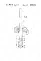
- FIGS. 1 and 2are, respectively a sectional elevation of the shell, and a side elevation of the stem, for a blind rivet, prior to assembly together;
- FIG. 3is a section on the line 3--3 of FIG. 1;
- FIG. 4is a sectional elevation showing the blind rivet assembly positioned and ready to be set in workpieces to be riveted, and showing part of a riveting tool for setting the blind rivet;
- FIGS. 5, 6 and 7are sectional elevations showing successive stages in the setting of the blind rivet.
- FIG. 8corresponds to FIG. 7 but shows a similar rivet used to rivet together workpieces of a greater total thickness.
- the self-plugging blind rivet assembly 10(FIG. 4) consists of two parts, namely, a tubular rivet shell 11 and a stem 12, which are assembled together.
- the rivet shellis made of aluminium alloy and has an elongate shank 13 and a radially enlarged head 14 formed integrally with the shank at one end (the head end) of the shell.
- the shellhas a bore 15 throughout its length, the diameter of the bore being increased at the head end by a head counterbore 16. Except for this, the bore 15 is of uniform diameter (subject to manufacturing tolerances) throughout its length.
- the head counterbore 16is shorter than the thickness of the head and provides a locking shoulder 17 at the junction between the bore 15 and counterbore 16.
- the locking shoulderface towards the head end of the shell.
- the tail end of the shellhas a flat face 18 perpendicular to the longitudinal axis of the shell.
- the shell shankis weakened over a zone 19 which extends from a position 21 spaced away from the tail end face 18 and extending along the shell shank nearly to the head 14.
- the weakened zonecomprises three longitudinal slits 22 spaced equiangularly around the shank.
- the slitsare made as narrow as practicable in the circumferential sense, and define between adjacent ones of them three longitudinal struts 23 which are separated from each other by the slits and which, when the shank is subjected to axial compression, will bend outwardly, as will become apparent.
- the tail-end portion 24 of the shell, between the end 21 of the weakened zone and the tail end face 18 of the shank,is of course stronger then the weakened zone.
- the underside of the head 14 which faces towards the tail end of the bodyis undercut to leave a circumferential sealing lip 25 surrounding a flat face 26 which receives a resilient sealing washer 27 (FIG. 4) which assists the formation of a seal between the shell head and a workpiece in which the rivet is installed.
- the stem 12is also made of aluminium alloy.
- the stemcomprises a plugging portion 31 which, after setting of the rivet, serves to plug the bore of the body, and an elongated pulling portion 32 which is joined to the plugging portion 31 by a breakneck.
- the pulling portionis of less external diameter than the plugging portion, and will pass through the shell bore 15 without interference.
- the breakneckis the weakest part along the length of the stem so that, when the stem is subjected to progressively increasing tension, it will break at the breakneck rather than elsewhere.
- the plugging portion 31is of uniform external diameter throughout its length (subject to manufacturing tolerances) and is an interference fit in the bore 15 of the tubular shell 11, and is appreciably shorter in length than the shell shank 13.
- the part of the plugging portion adjacent the breakneckis formed with a cylindrical cleavage 34 (see FIG. 4) which extends into the plugging portion plug in the longitudinal direction away from the breakneck.
- the cleavagehas a diameter the same as, or minutely greater than, that of the pulling portion 32, and differentiates the part of the plugging portion adjacent to the breakneck into a central cylindrical core 35 of substantially the same diameter as the pulling portion 32, and a skirt 36 which peripherally surrounds the core 35, the skirt being integrally joined with the remainder of the plugging portion in the region further from the breakneck than the cleavage extends.
- the skirtpresents an annular face or step 37 which faces towards the pulling portion 32.
- the skirtis deformable, by means of a suitable riveting tool, to form an outwardly directed flange capable of abutting the locking shoulder 17 in the body, and thus provides locking means for locking the plugging portion in the shell of the rivet.
- An enlarged annular bead 33 at the breakneckhas tapered sides and a diameter larger than that of the cleavage 34 but smaller than that of the skirt.
- the plugging portion 31is formed with a radially enlarged head 38 at the end remote from the breakneck.
- This headhas an underhead surface 39 having an extreme diameter slightly less than that of the shell shank end face 18.
- the underhead face 39is not absolutely flat but is in the form of a very shallow convex cone, having an included angle of about 170 degress (an absolutely flat face would have an included angle of 180 degrees).
- the outer edge 40 of the underhead surface 39is a sharp edge, and the peripheral face 41 of the head 38 is cylindrical i.e. of uniform diameter throughout its length.
- the shell and stemare assembled by inserting the pulling portion 32 of the stem into the tail end of the shell and passing it along the bore until the plugging portion 31 meets the tail end of the shell. Sufficient force is then exerted to drive the pulling portion into the bore, in which it is an interference fit. It may be desirable to support the exterior of the shell in a die or other form of peripheral clamp, to prevent radical expansion of the shell as the plugging portion is driven in.
- the stemis thus forced into the shell until the underface 39 of the stem head 38 contacts the end face 18 of the shell.
- the stem and shellare thus assembled, i.e. in the condition illustrated in FIG. 4.
- the breaknecklies about one third of the way along the weakened zone 19.
- the pulling portion 32 of the stemprojects from the head end of the shell.
- An apertured panel member 42(which may be of a soft or easily fractured material such as glass fibre reinforced plastics material) may be fastened to another apertured member 43 (which may, for example, be a metallic support member for the panel), by bringing the members together with their apertures 44 in register and inserting the shell shank through the apertures until the sealing washer 27 under the head 14 abuts the face 45 of the member nearer the operator, and the tail-end portion 24 and at least a portion of the weakened zone of the shell shank projects beyond the back or blind face 46 of the workpieces.
- the diameter of the apertures 44 in the panelsis of course made very slightly larger than the external diameter of the shell shank.
- the rivetcan be set by means of a rivet setting tool of a known kind sold under the Registered Trade Mark “AVDEL” and comprising means (not shown) for gripping and pulling the pulling portion 32 of the stem which projects from the head of the rivet shell.
- APDELRegistered Trade Mark
- the toolhas annular anvil 47 for abutting the head of the shell and a projecting rim 48 for deforming the locking skirt.
- the toolis offered up to the rivet so that the pulling portion 32 passes through the anvil 47 into engagement with the gripping and pulling means, and the anvil abuts the shell head 14.
- the toolis then operated to pull the stem axially relative to the rivet shell, in a direction to draw the plugging portion 31 towards the head 14 of the shell with a progressively increasing force.
- the shell shank tail portion 24begins to move with the stem towards the shell head 14, accompanied by an outward bending of the three struts 23 at a position generally half-way between the blind face 46 of the panel 42 which constrains the portions of the struts within it against radial expansion and the tail portion 24 of the shell body (see FIG. 5).
- the plugging portion 31moves through the outwardly expanded struts and into the part of the shank which extends within the thickness of the workpiece members 42 and 43, slightly expanding the shank radially. This movement of the shell tail portion 31 with the stem continues until the three struts are bent and forced firmly into abutment with the blind face 46, as shown in FIG. 6, so as to constitute a blind head 49 of greater transverse dimension than the apertures of the workpiece.
- the force required to move the shell tail portion 24 nearer to the head 14increases abruptly, to the extent that, by applying sufficient force, the stem head 41 causes the tail end part 24 of the shell to deform outwardly, so that the head 41 enters into the tail end part 24 of the shell.
- the rimhas an inclined front which, as the plugging portion is drawn towards it, is guided by the bead 33 to engage the skirt annular face 37 and enters the cleavage 34, so as to progressively deforms the locking skirt 36 radially outwardly, away from the central core 35 of the plugging portion. It thereby forms a radially enlarged locking flange 51 (FIG. 7) which abuts at least the inner peripheral edge of the locking shoulder 17, thereby constituting an obstacle to withdrawal of the plugging portion from the body.
- the force required to pull the stemfurther increases abruptly, because of the engagement with the anvil rim 48.
- the breakneckfractures, leaving the plugging portion 31 locked in the body, while the pulling portion 32 becomes detached and can be discarded, as shown in FIG. 7.
- the fracture face 52 of the plugging portionis about level with, or just inside, the face of the shell head.
- the washer 27seals the shell head 14 to the front face 45 of the panel, around the aperture 44.
- the interference fit of the plugging portion 31 in the part of the shell shank within the panelsseals the plugging portion to the shell.
- FIGS. 4, 5, 6 and 7,the example rivet assembly is illustrated being used to fasten together two sheets 42, 43 of a total thickness (or "grip", as the total workpiece thickness is known in the art of blind riveting) which is about the minimum value for which the example rivet assembly can be used.
- a total thicknessor "grip", as the total workpiece thickness is known in the art of blind riveting
- FIG. 8illustrates the use of a similar rivet to fasten together sheets having a grip the maximum value for which this rivet will work successfully.
- FIG. 8illustrates the fully installed condition of the rivet assembly, and comparison with FIG. 7 shows that, since a much shorter length of the struts 32 produces from the blind panel face, a radially smaller blind head 49 results.
- the shell shankcontracts axially by a much smaller amount due to the shorter folded length of the struts. Since the plugging portion has still been pulled through the shell bore until the locking skirt lies in the shell head conterbore 16, the stem head 41 has necessarily been pulled into the shell bore by a much greater distance than in the minimum grip condition illustrated in FIG. 7.
- the maximum gripis determined in practice by the limitations that in the fully installed condition, the stem head 44 cannot enter into the space within the panels, and that the blind head 49 must be large enough to secure the rear panel.
- the sharp leading edge of the headmay cut a ring of material from the shell tail portion 24 (most probably from adjacent the tail end face 18 of the shell).
- the plugging portionhas an uniform external diameter throughout its length (apart from the head), and the shell bore also has a uniform diameter throughout its length (apart from the head end counterbore). Furthermore assembly of the stem and shell is simple, merely requiring the forcing of one into the other.
- the form of the shellmay be modified in various ways.
- the material of the shankcould be punched out to form slots.
- the shankcould merely be formed with longitudinal shear lines or grooves so as to provide longitudinal weakening of the collapsible part of the shank such as to enable it, on being compressed axially, to split into a plurality of longitudinal struts which can be bent or bowed outwardly until doubled and thereby form a radially enlargeg blind head.
- the sealing washer 47may be omitted from beneath the shell head.
- the precise form of the stem head 38may be modified.
- the conical angle of the underhead face 39may be greater, up to and including the case where the face is flat. Alternatively it may be somewhat less than the 170 degrees.
- the peripheral face 41 of the stem headmay not be cylindrical, but could taper outwardly from its leading edge 40. Such taper would be slight, having an included angle in the range from 0 degrees to about 5 degrees.
- Variation of the precise shape of underhead face 39is believed to alter the value of pulling tension at which the stem head initially enters the shell tail, and variation of the precise shape of the stem head peripheral face 41 is believed to alter the tension thereafter required to pull the stem head into the shell tail.
Landscapes
- Engineering & Computer Science (AREA)
- General Engineering & Computer Science (AREA)
- Mechanical Engineering (AREA)
- Insertion Pins And Rivets (AREA)
Abstract
Description
This invention relates to a blind rivet assembly. More particularly it relates to a blind rivet assembly of the so-called "self-plugging" type, which comprises a tubular shell and a stem, and in which part of the stem remains in the shell of the installed rivet to plug the tubular shell. A blind rivet is one which can be set without access to the remote or blind side of the workpieces.
Rivets of this general kind are well known and have been made in a variety of different forms in order to meet various specific requirements.
The present invention provides blind rivet assembly comprising a tubular shell and a stem;
the shell having an elongate shank, a head at one end, and a bore throughout the head and shank;
the shell bore having a radially enlarged counterbore at its head end and an annular locking shoulder facing towards the head end at the junction of the counterbore and the remainder of the bore;
the shell shank being weakened over a zone which extends longitudinally of the shank from a position spaced from the tail end (i.e. the end thereof remote from the head) of the shank towards the head end;
the stem extending through the bore of the shell and having an elongate pulling portion which projects from the head end of the shell, and an elongate plugging portion connected to the pulling portion by a breakneck and disposed substantially with the shell shank bore;
the plugging portion being formed with a radially enlarged stem head at the end thereof remote from the breakneck, and disposed beyond the tail end of the shank;
whereby, when the assemby is inserted through aligned apertures in workpieces to be thereby riveted together so that at least part of the shell shank weekened zone projects beyond the workpieces on the blind side thereof, and the pulling portion of the stem is pulled with increasing tension with respect to the shell;
firstly compression exerted by the stem head on the shell shank tail end causes radial enlargement of at least part of the weakened zone of the shell shank to form a blind head, whilst the plugging portion moves through the shell bore towards the head end thereof;
and thereafter the shell shank tail end deforms to allow the entry of the stem head thereinto;
thereafter the part of the plugging portion adjacent to breakneck being deformable into locking engagement with the annular locking shoulder of the shell counterbore, and the stem being fracturable at the breakneck to leave the plugging portion plugging the shell bore.
Other preferred features of the invention will become apparent from the appended claims. An embodiment of the invention will now be described, by way of example, and with reference to the accompanying drawings in which:
FIGS. 1 and 2 are, respectively a sectional elevation of the shell, and a side elevation of the stem, for a blind rivet, prior to assembly together;
FIG. 3 is a section on theline 3--3 of FIG. 1;
FIG. 4 is a sectional elevation showing the blind rivet assembly positioned and ready to be set in workpieces to be riveted, and showing part of a riveting tool for setting the blind rivet;
FIGS. 5, 6 and 7 are sectional elevations showing successive stages in the setting of the blind rivet; and
FIG. 8 corresponds to FIG. 7 but shows a similar rivet used to rivet together workpieces of a greater total thickness.
The self-plugging blind rivet assembly 10 (FIG. 4) consists of two parts, namely, atubular rivet shell 11 and a stem 12, which are assembled together.
The rivet shell is made of aluminium alloy and has anelongate shank 13 and a radially enlargedhead 14 formed integrally with the shank at one end (the head end) of the shell. The shell has abore 15 throughout its length, the diameter of the bore being increased at the head end by ahead counterbore 16. Except for this, thebore 15 is of uniform diameter (subject to manufacturing tolerances) throughout its length.
Thehead counterbore 16 is shorter than the thickness of the head and provides a lockingshoulder 17 at the junction between thebore 15 andcounterbore 16. The locking shoulder face towards the head end of the shell. The tail end of the shell has aflat face 18 perpendicular to the longitudinal axis of the shell.
The shell shank is weakened over a zone 19 which extends from aposition 21 spaced away from thetail end face 18 and extending along the shell shank nearly to thehead 14. The weakened zone comprises threelongitudinal slits 22 spaced equiangularly around the shank. The slits are made as narrow as practicable in the circumferential sense, and define between adjacent ones of them threelongitudinal struts 23 which are separated from each other by the slits and which, when the shank is subjected to axial compression, will bend outwardly, as will become apparent.
The tail-end portion 24 of the shell, between theend 21 of the weakened zone and thetail end face 18 of the shank, is of course stronger then the weakened zone.
The underside of thehead 14 which faces towards the tail end of the body is undercut to leave acircumferential sealing lip 25 surrounding aflat face 26 which receives a resilient sealing washer 27 (FIG. 4) which assists the formation of a seal between the shell head and a workpiece in which the rivet is installed.
The stem 12 is also made of aluminium alloy. The stem comprises a pluggingportion 31 which, after setting of the rivet, serves to plug the bore of the body, and anelongated pulling portion 32 which is joined to the pluggingportion 31 by a breakneck. The pulling portion is of less external diameter than the plugging portion, and will pass through the shell bore 15 without interference.
The breakneck is the weakest part along the length of the stem so that, when the stem is subjected to progressively increasing tension, it will break at the breakneck rather than elsewhere. Theplugging portion 31 is of uniform external diameter throughout its length (subject to manufacturing tolerances) and is an interference fit in thebore 15 of thetubular shell 11, and is appreciably shorter in length than theshell shank 13.
To enable theplugging portion 31 to be locked to theshell 11 during setting of the rivet, the part of the plugging portion adjacent the breakneck is formed with a cylindrical cleavage 34 (see FIG. 4) which extends into the plugging portion plug in the longitudinal direction away from the breakneck. The cleavage has a diameter the same as, or minutely greater than, that of thepulling portion 32, and differentiates the part of the plugging portion adjacent to the breakneck into a central cylindrical core 35 of substantially the same diameter as thepulling portion 32, and askirt 36 which peripherally surrounds the core 35, the skirt being integrally joined with the remainder of the plugging portion in the region further from the breakneck than the cleavage extends. The skirt presents an annular face orstep 37 which faces towards thepulling portion 32. The skirt is deformable, by means of a suitable riveting tool, to form an outwardly directed flange capable of abutting the lockingshoulder 17 in the body, and thus provides locking means for locking the plugging portion in the shell of the rivet. An enlargedannular bead 33 at the breakneck has tapered sides and a diameter larger than that of thecleavage 34 but smaller than that of the skirt.
The pluggingportion 31 is formed with a radially enlargedhead 38 at the end remote from the breakneck. This head has anunderhead surface 39 having an extreme diameter slightly less than that of the shellshank end face 18. In this example theunderhead face 39 is not absolutely flat but is in the form of a very shallow convex cone, having an included angle of about 170 degress (an absolutely flat face would have an included angle of 180 degrees). Theouter edge 40 of theunderhead surface 39 is a sharp edge, and theperipheral face 41 of thehead 38 is cylindrical i.e. of uniform diameter throughout its length.
The shell and stem are assembled by inserting thepulling portion 32 of the stem into the tail end of the shell and passing it along the bore until theplugging portion 31 meets the tail end of the shell. Sufficient force is then exerted to drive the pulling portion into the bore, in which it is an interference fit. It may be desirable to support the exterior of the shell in a die or other form of peripheral clamp, to prevent radical expansion of the shell as the plugging portion is driven in. The stem is thus forced into the shell until theunderface 39 of thestem head 38 contacts theend face 18 of the shell. The stem and shell are thus assembled, i.e. in the condition illustrated in FIG. 4. The breakneck lies about one third of the way along the weakened zone 19. The pullingportion 32 of the stem projects from the head end of the shell.
The interference between theplugging portion 31 and the interior of theshell shank 13 maintains the parts of the rivet in an assembled condition ready for use.
The use of the assembledrivet 10 to fasten together apertured workpiece members will now be described.
An apertured panel member 42 (which may be of a soft or easily fractured material such as glass fibre reinforced plastics material) may be fastened to another apertured member 43 (which may, for example, be a metallic support member for the panel), by bringing the members together with their apertures 44 in register and inserting the shell shank through the apertures until the sealing washer 27 under thehead 14 abuts theface 45 of the member nearer the operator, and the tail-end portion 24 and at least a portion of the weakened zone of the shell shank projects beyond the back orblind face 46 of the workpieces. The diameter of the apertures 44 in the panels is of course made very slightly larger than the external diameter of the shell shank.
The rivet can be set by means of a rivet setting tool of a known kind sold under the Registered Trade Mark "AVDEL" and comprising means (not shown) for gripping and pulling thepulling portion 32 of the stem which projects from the head of the rivet shell. As illustrated in FIGS. 4, 5 and 6, the tool hasannular anvil 47 for abutting the head of the shell and a projectingrim 48 for deforming the locking skirt. The tool is offered up to the rivet so that thepulling portion 32 passes through theanvil 47 into engagement with the gripping and pulling means, and the anvil abuts theshell head 14. The tool is then operated to pull the stem axially relative to the rivet shell, in a direction to draw theplugging portion 31 towards thehead 14 of the shell with a progressively increasing force.
Due to the abutment between theface 39 of thestem head 41 and theend face 18 of the shell tail, axial compression is exerted on the shell. Since the weakest portion of the shell is the weakened zone, it is the weakened zone which deforms first. The shellshank tail portion 24 begins to move with the stem towards theshell head 14, accompanied by an outward bending of the threestruts 23 at a position generally half-way between theblind face 46 of thepanel 42 which constrains the portions of the struts within it against radial expansion and thetail portion 24 of the shell body (see FIG. 5). The pluggingportion 31 moves through the outwardly expanded struts and into the part of the shank which extends within the thickness of theworkpiece members shell tail portion 31 with the stem continues until the three struts are bent and forced firmly into abutment with theblind face 46, as shown in FIG. 6, so as to constitute ablind head 49 of greater transverse dimension than the apertures of the workpiece.
At this stage, the force required to move theshell tail portion 24 nearer to thehead 14 increases abruptly, to the extent that, by applying sufficient force, thestem head 41 causes thetail end part 24 of the shell to deform outwardly, so that thehead 41 enters into thetail end part 24 of the shell.
Continued pulling of the mandrel by the tool eventually brings the plugging portion into engagement with the projectingannular rim 48 which projects forwardly of the anvil into theshell head counterbore 16. The rim has an inclined front which, as the plugging portion is drawn towards it, is guided by thebead 33 to engage the skirtannular face 37 and enters thecleavage 34, so as to progressively deforms the lockingskirt 36 radially outwardly, away from the central core 35 of the plugging portion. It thereby forms a radially enlarged locking flange 51 (FIG. 7) which abuts at least the inner peripheral edge of the lockingshoulder 17, thereby constituting an obstacle to withdrawal of the plugging portion from the body. Once the skirt is fully deformed, the force required to pull the stem further increases abruptly, because of the engagement with theanvil rim 48. On applying sufficient further force, therefore, the breakneck fractures, leaving the pluggingportion 31 locked in the body, while the pullingportion 32 becomes detached and can be discarded, as shown in FIG. 7. The fracture face 52 of the plugging portion is about level with, or just inside, the face of the shell head.
The residual tension on the stem clamps thepanels blind face 46 this clamping is transmitted through theblind rivet head 49, which is of substantial radial extent. On thefront face 45 the clamping is exerted through the shellhead sealing washer 27. It may be that if the residual tension is sufficient, the sealing washer is compressed sufficiently that therim 25 contracts theface 45 of the panel.
Thewasher 27 seals theshell head 14 to thefront face 45 of the panel, around the aperture 44. The interference fit of the pluggingportion 31 in the part of the shell shank within the panels seals the plugging portion to the shell. There is no need for thestem head 41 to seal within the shell tail portion 24 (provided it is mechanically locked therein), because the interior of the shell shank bore is open to the outside space through theslots 22.
In FIGS. 4, 5, 6 and 7, the example rivet assembly is illustrated being used to fasten together twosheets struts 32 produces from the blind panel face, a radially smallerblind head 49 results. Also the shell shank contracts axially by a much smaller amount due to the shorter folded length of the struts. Since the plugging portion has still been pulled through the shell bore until the locking skirt lies in the shell head conterbore 16, thestem head 41 has necessarily been pulled into the shell bore by a much greater distance than in the minimum grip condition illustrated in FIG. 7.
The maximum grip is determined in practice by the limitations that in the fully installed condition, the stem head 44 cannot enter into the space within the panels, and that theblind head 49 must be large enough to secure the rear panel.
When thestem 41 is pulled into the rivet shell, it is found that, depending on the precise circumstances of each particular placing operation, the sharp leading edge of the head may cut a ring of material from the shell tail portion 24 (most probably from adjacent the tail end face 18 of the shell).
The means by which, in the foregoing embodiment, the formation of a blind head is achieved during setting of the rivet, and by which the plugging portion is enabled to become disengaged from the tail-end portion of the rivet shell may also be modified slightly, as is mentioned below. A number of suitable solutions have been proposed in the past in connection with pull-to-set self-plugging blind rivets. However, it is believed that the solution to this problem described in the foregoing example offers advantages in that, on the one hand it facilitates good control over the different forces required at different stages of the setting operation, and at the same time enables a single size of rivet to be versatile in the range of thickness of workpiece (i.e. "grip range") which can be accommodated. It also makes manufacture of the stem and shell simple, since as described the plugging portion has an uniform external diameter throughout its length (apart from the head), and the shell bore also has a uniform diameter throughout its length (apart from the head end counterbore). Furthermore assembly of the stem and shell is simple, merely requiring the forcing of one into the other.
The invention is not restricted to the details of the foregoing example. For instance the form of the shell may be modified in various ways. In particular, instead of having threestruts 22 there could be only two, or a greater number, for example six, made by appropriately varying the number of slits. Furthermore, the material of the shank could be punched out to form slots. Alternatively, the shank could merely be formed with longitudinal shear lines or grooves so as to provide longitudinal weakening of the collapsible part of the shank such as to enable it, on being compressed axially, to split into a plurality of longitudinal struts which can be bent or bowed outwardly until doubled and thereby form a radially enlargeg blind head.
The sealingwasher 47 may be omitted from beneath the shell head.
As previously mentioned, the precise form of thestem head 38 may be modified. The conical angle of theunderhead face 39 may be greater, up to and including the case where the face is flat. Alternatively it may be somewhat less than the 170 degrees. Similarly, theperipheral face 41 of the stem head may not be cylindrical, but could taper outwardly from its leadingedge 40. Such taper would be slight, having an included angle in the range from 0 degrees to about 5 degrees. Variation of the precise shape ofunderhead face 39 is believed to alter the value of pulling tension at which the stem head initially enters the shell tail, and variation of the precise shape of the stem headperipheral face 41 is believed to alter the tension thereafter required to pull the stem head into the shell tail.
Claims (12)
1. A blind rivet assembly comprising:
a shell having an elongate shank, a head at one end, and a bore throughout the head and shank;
a shell bore having a radially enlarged counterbore at a head end thereof and an annular locking shoulder facing towards the head end at a junction of the counterbore and a remainder of the bore;
a shell shank having a weakened zone which extends longitudinally of the shank from a position spaced from the tail end of the shank towards the head end thereof;
a stem extending through the bore of the shell and having an elongate pulling portion which projects from the head end of the shell, and an elongate plugging portion connected to the pulling portion by a breakneck and disposed substantially within the shell shank bore, the plugging portion being formed with a radially enlarged stem head at the end thereof remote from the breakneck, and disposed beyond the tail end of the shank, the plugging portion having a diameter greater than a diameter of the pulling portion;
a cylindrical skirt surrounding a portion of said plugging portion adjacent said breakneck and forming an extension of said plugging portion, said skirt having an annular face facing said pulling portion and being separated from said plugging portion by a cleavage having a diameter substantially the same as said pulling portion; and
an annular enlarged diameter bead defined on said pulling portion adjacent said breakneck, said bead having a tapered side and a diameter smaller than that of said skirt and greater than that of said cleavage;
whereby, when the assembly is inserted through aligned apertures in workpieces to be thereby riveted together so that at least part of the shell shank zone projects beyond the workpiece on the blind side thereof, and the pulling portion of the stem is pulled with the increasing tension with respect to the shell by a pulling tool, compression exerted by the stem head on the shell shank tail end causes radial enlargement of at least part of the weakened zone of the shell shank to form a blind head, while the plugging portion moves through the shell bore towards the head end thereof and thereafter the shell shank tail end deforms to allow the entry of the stem head thereinto, and thereafter the skirt is deformable into locking engagement with the annular locking shoulder of the shell counterbore by a projecting rim of the tool, and the stem is fracturable at the breakneck to leave the plugging portion plugging the shell bore, whereby said annular bead guides said projecting rim into alignment with said skirt face.
2. A blind rivet assembly as claimed in claim 1, in which the weakened zone of the shell shank comprises a plurality of circumferentially spaced lines of weakness extending longitudinally of the shank.
3. A blind rivet assembly as claimed in claim 2, in which the lines of weakness comprise slots extending radially through the shank.
4. A blind rivet assembly as claimed in claim 1, in which the plugging portion of the stem is in interference fit in the bore of the shell shank.
5. A blind rivet assembly as claimed in claim 1, in which the bore of the shell shank, apart from the counterbore at the head end, is of substantially, uniform diameter throughout its length.
6. A blind rivet assembly asclaimed in claim 1, in which the plugging portion of the stem, apart from the radially enlarged head, is a substantially uniform diameter throughout its length.
7. A blind rivet assembly as claimed in claim 1, in which the radially enlarged stem head is initially in contact with the adjacent tail end of the shell shank.
8. A blind rivet assembly as claimed in claim 1, in which the stem head has a surface, which faces towards the shell shank, which surface is substantially flat.
9. A blind rivet assembly as claimed in claim 1, in which the stem head has a surface, which faces towards the shell shank, which surface is bounded by a sharp edge.
10. A blind rivet assembly as claimed in claim 9, in which the surface has a diameter which is less than the external diameter of the shell shank at the tail end thereof.
11. A blind rivet assembly as claimed in claim 1, in which the stem head has a peripheral surface which is substantially cylindrical with its minimum diameter at the end thereof which is nearer the shell shank.
12. A blind rivet assembly as claimed in claim 11, in which the uncluded angle of the taper is not more than 10 degrees.
Applications Claiming Priority (2)
| Application Number | Priority Date | Filing Date | Title |
|---|---|---|---|
| GB08306188AGB2136075B (en) | 1983-03-07 | 1983-03-07 | Rivet |
| GB8306188 | 1983-03-07 |
Publications (1)
| Publication Number | Publication Date |
|---|---|
| US4580936Atrue US4580936A (en) | 1986-04-08 |
Family
ID=10539110
Family Applications (1)
| Application Number | Title | Priority Date | Filing Date |
|---|---|---|---|
| US06/584,634Expired - LifetimeUS4580936A (en) | 1983-03-07 | 1984-02-29 | Blind rivet assembly |
Country Status (8)
| Country | Link |
|---|---|
| US (1) | US4580936A (en) |
| JP (1) | JPS59166708A (en) |
| AU (1) | AU564123B2 (en) |
| CA (1) | CA1244269A (en) |
| DE (1) | DE3407464A1 (en) |
| FR (1) | FR2542396B1 (en) |
| GB (1) | GB2136075B (en) |
| IT (1) | IT1180686B (en) |
Cited By (67)
| Publication number | Priority date | Publication date | Assignee | Title |
|---|---|---|---|---|
| US4869629A (en)* | 1988-07-22 | 1989-09-26 | Textron Inc. | Blind fastener |
| US5326205A (en)* | 1992-05-27 | 1994-07-05 | Anspach Jr William E | Expandable rivet assembly |
| US5501695A (en)* | 1992-05-27 | 1996-03-26 | The Anspach Effort, Inc. | Fastener for attaching objects to bones |
| US5599147A (en)* | 1995-05-02 | 1997-02-04 | Allfast Fastening Systems, Inc. | Blind rivet with a tapered locking mechanism |
| US5603592A (en)* | 1994-10-03 | 1997-02-18 | Huck International, Inc. | High strength blind bolt with uniform high clamp over an extended grip range |
| US5689873A (en)* | 1996-01-11 | 1997-11-25 | Allfast Fastening Systems, Inc. | Tacking fastener |
| US5741099A (en)* | 1996-05-17 | 1998-04-21 | Asar Group, Inc. | Self tapping blind setting rivet assembly |
| US5762456A (en)* | 1996-05-17 | 1998-06-09 | Asar Group, Inc. | Self tapping blind setting bolt rivet assembly |
| US5868370A (en)* | 1996-11-25 | 1999-02-09 | Itw De France | Fixing device, fastening support incorporating it, and its use for a vehicle sun visor |
| US5899938A (en)* | 1996-11-27 | 1999-05-04 | Joseph H. Sklar | Graft ligament anchor and method for attaching a graft ligament to a bone |
| US5906462A (en)* | 1997-12-10 | 1999-05-25 | Siemens Energy & Automation, Inc. | Use of a blind rivet to retain a mechanical frame into a plastic base |
| US5915901A (en)* | 1996-07-12 | 1999-06-29 | Asar Group, Inc. | Blind setting rivet assembly |
| US5957641A (en)* | 1996-07-18 | 1999-09-28 | B & B Hardware, Inc. | Headed fastener with precisely calculated groove under head to accommodate O'ring sealing member as a self-sealing assembly |
| WO1999062417A1 (en) | 1998-06-04 | 1999-12-09 | Synthes Ag Chur | Surgical blind rivet with closing element |
| WO1999064751A1 (en)* | 1998-06-05 | 1999-12-16 | Textron Fastening Systems Limited | Method of forming a tubular member |
| US6077009A (en)* | 1999-04-09 | 2000-06-20 | Huck International, Inc. | Blind fastener with high strength blind head and high clamp and high shear load resistance |
| US6221107B1 (en) | 1998-08-03 | 2001-04-24 | Mark E. Steiner | Ligament fixation device and method |
| FR2825762A1 (en)* | 2001-06-11 | 2002-12-13 | Peugeot Citroen Automobiles Sa | Rivet useful for fixing together parts of an automobile includes a sealing device comprising an annular seal that forms a seal with a flange on the rivet casing |
| US6533816B2 (en) | 1999-02-09 | 2003-03-18 | Joseph H. Sklar | Graft ligament anchor and method for attaching a graft ligament to a bone |
| US6554862B2 (en) | 1996-11-27 | 2003-04-29 | Ethicon, Inc. | Graft ligament anchor and method for attaching a graft ligament to a bone |
| US20030093890A1 (en)* | 2001-10-25 | 2003-05-22 | Ralph Luhm | Two piece tack rivets and method of forming holes for permanent fasteners |
| GB2388063A (en)* | 2002-04-23 | 2003-11-05 | Emhart Llc | Improved peel-type blind rivet |
| US20040110569A1 (en)* | 2002-12-06 | 2004-06-10 | Avk Industrial Products, A Division Of Sps Technologies Inc. | Blind threaded fastener forming technique |
| US6796759B2 (en) | 2001-01-12 | 2004-09-28 | A. L. Pepper Aasgaard, III | Self-polishing and tapping rivet assembly |
| US20040223832A1 (en)* | 2003-05-05 | 2004-11-11 | Aasgaard A.L. Pepper | Blind-setting coring rivet assembly |
| US20040228706A1 (en)* | 2003-05-13 | 2004-11-18 | Jones Steven V. | Blind fastener |
| US20040236336A1 (en)* | 2001-06-07 | 2004-11-25 | Opus Medical, Inc. | Method and apparatus for attaching connective tissues to bone using a suture anchoring device |
| USRE38664E1 (en) | 1996-01-11 | 2004-11-30 | Allfast Fastening Systems, Inc. | Method for creating a hole for a permanent fastener that replaces a tacking fastener |
| US20050143825A1 (en)* | 2002-07-09 | 2005-06-30 | Albert Enayati | Intervertebral prosthesis |
| US20050277986A1 (en)* | 2001-02-12 | 2005-12-15 | Arthrocare Corporation | Knotless suture lock apparatus and method for securing tissue |
| US20060002784A1 (en)* | 2004-07-01 | 2006-01-05 | Curtis David A W | Fastener apparatus for roofing and steel building construction |
| US7083647B1 (en) | 1996-11-27 | 2006-08-01 | Sklar Joseph H | Fixation screw, graft ligament anchor assembly, and method for securing a graft ligament in a bone tunnel |
| US20060271105A1 (en)* | 2002-11-19 | 2006-11-30 | Foerster Seth A | Devices and methods for repairing soft tissue |
| US20060271060A1 (en)* | 2005-05-26 | 2006-11-30 | Arthrocare Corporation | Threaded knotless suture anchoring device and method |
| US20070059120A1 (en)* | 2005-09-15 | 2007-03-15 | Vigliotti Daniel P | Blind rivet and method |
| US20070243036A1 (en)* | 2006-03-14 | 2007-10-18 | Pao-Jen Chen | Structure enhanced waterproof pull nail |
| US20080015594A1 (en)* | 1999-12-30 | 2008-01-17 | Arthrocare Corporation | Methods for attaching connective tissues to bone using a multi-component anchor |
| US20080051836A1 (en)* | 2006-08-03 | 2008-02-28 | Seth Foerster | Method and apparatus for attaching connective tissues to bone using a knotless suture anchoring device |
| US20080091206A1 (en)* | 2006-10-13 | 2008-04-17 | Jeffrey Johnson | Bone Plate |
| US20080161864A1 (en)* | 2006-09-29 | 2008-07-03 | Depuy Mitek, Inc. | Femoral fixation |
| US20080319478A1 (en)* | 2007-04-25 | 2008-12-25 | Foerster Seth A | Knotless suture anchor having discrete polymer components and related methods |
| US20090024149A1 (en)* | 2007-07-17 | 2009-01-22 | Wilson-Cook Medical Inc. | Rivet introduction system |
| US20090069823A1 (en)* | 2007-09-12 | 2009-03-12 | Foerster Seth A | Implant and delivery system for soft tissue repair |
| USD592946S1 (en) | 2007-07-25 | 2009-05-26 | Spinal U.S.A. | Locking rivet head |
| US20090222040A1 (en)* | 2001-02-12 | 2009-09-03 | Arthrocare Corporation | Methods and devices for attaching connective tissues to bone using a knotless suture anchoring device |
| US20090281625A1 (en)* | 2008-05-06 | 2009-11-12 | Rhausler, Inc. | Expandable intervertebral implant |
| US20100101177A1 (en)* | 2008-10-23 | 2010-04-29 | Mcgee Thomas | Anchor device with double-sectioned head and method of using the same |
| US7901456B2 (en) | 2001-09-28 | 2011-03-08 | Ethicon, Inc. | Expanding ligament graft fixation system method |
| CN102747959A (en)* | 2012-07-12 | 2012-10-24 | 赵群燕 | Method for fixing object and expansion bolt and special borer for method |
| US20120305709A1 (en)* | 2011-05-31 | 2012-12-06 | Airbus Operations Gmbh | Connection arrangement, particularly for aircraft structure parts |
| CN103527596A (en)* | 2013-10-30 | 2014-01-22 | 无锡安士达五金有限公司 | Titanium alloy folding shockproof rivet |
| US8657854B2 (en) | 2001-02-12 | 2014-02-25 | Arthrocare Corporation | Knotless suture anchoring device having deforming section to accommodate sutures of various diameters |
| US20140271039A1 (en)* | 2013-03-15 | 2014-09-18 | Pcc Structurals, Inc. | Blind, bulbing, tacking rivet and method of installation |
| US20140314513A1 (en)* | 2011-08-26 | 2014-10-23 | Newfrey Llc | Blind rivet with a plastic rivet body |
| US9023083B2 (en) | 2012-01-27 | 2015-05-05 | Arthrocare Corporation | Method for soft tissue repair with free floating suture locking member |
| US9034014B2 (en) | 2012-01-27 | 2015-05-19 | Arthrocare Corporation | Free floating wedge suture anchor for soft tissue repair |
| US9198649B2 (en) | 2012-01-27 | 2015-12-01 | Arthrocare Corporation | Rotating locking member suture anchor and method for soft tissue repair |
| US9226742B2 (en) | 2012-01-27 | 2016-01-05 | Arthrocare Corporation | Restricted wedge suture anchor and method for soft tissue repair |
| US9316243B2 (en) | 2010-11-11 | 2016-04-19 | Henrob Limited | Method for forming a joint in a stack of light metal alloy sheets |
| US9364210B2 (en) | 2012-01-27 | 2016-06-14 | Arthrocare Corporation | Biased wedge suture anchor and method for soft tissue repair |
| US9636101B2 (en) | 2011-09-01 | 2017-05-02 | Arthrocare Corporation | Bone anchor having an integrated stress isolator |
| US9855028B2 (en) | 2012-04-06 | 2018-01-02 | Arthrocare Corporation | Multi-suture knotless anchor for attaching tissue to bone and related method |
| US10603091B2 (en) | 2014-02-24 | 2020-03-31 | Curtin University Of Technology | Fastener |
| US10920813B2 (en)* | 2017-02-22 | 2021-02-16 | Bollhoff Otalu S.A. | Insert to be crimped, fixing part and assembly comprising one such insert and methods for manufacturing such parts |
| CN115502905A (en)* | 2022-05-26 | 2022-12-23 | 鲁般智慧(深圳)科技有限公司 | Sealing element clamp, assembling equipment and assembling method |
| US20230037581A1 (en)* | 2020-04-28 | 2023-02-09 | HELLA GmbH & Co. KGaA | Rivet sleeve and blind rivet with a rivet sleeve |
| US12251168B2 (en) | 2021-05-28 | 2025-03-18 | Medos International Sarl | Systems, methods, and devices for localized tracking of a vertebral body or other anatomic structure |
Families Citing this family (6)
| Publication number | Priority date | Publication date | Assignee | Title |
|---|---|---|---|---|
| CA1253017A (en)* | 1983-09-29 | 1989-04-25 | Usm Corporation | Large secondary head rivet |
| IT1182207B (en)* | 1984-05-30 | 1987-09-30 | George Siebol | IMPROVEMENT IN BLIND RIVET COMPLEXES WITH SELF-REGULATING LOCKING PIN |
| DE3942482C1 (en)* | 1989-12-22 | 1991-01-24 | Ulrich 2359 Henstedt-Ulzburg De Schildknecht | |
| GB2388880B (en)* | 2002-04-23 | 2005-10-19 | Emhart Llc | Improved blind rivet |
| JP5830819B2 (en)* | 2011-06-21 | 2015-12-09 | ポップリベット・ファスナー株式会社 | How to attach the metal collar |
| DE102013103615A1 (en)* | 2013-04-10 | 2014-10-30 | Dr. Ing. H.C. F. Porsche Aktiengesellschaft | Blind rivet and blind rivet connection |
Citations (5)
| Publication number | Priority date | Publication date | Assignee | Title |
|---|---|---|---|---|
| US2536353A (en)* | 1944-12-14 | 1951-01-02 | United Shoe Machinery Corp | Two-part rivet |
| US3055255A (en)* | 1957-03-25 | 1962-09-25 | Avdel Ltd | Blind rivet with internal mandrel supporting element |
| US3230818A (en)* | 1963-05-31 | 1966-01-25 | Olympic Screw & Rivet Corp | Pull-type blind rivet |
| US4046053A (en)* | 1975-04-01 | 1977-09-06 | Aerpat A.G. | Blind rivet |
| US4355934A (en)* | 1979-09-28 | 1982-10-26 | Aerpat A.G. | Self-plugging blind rivet |
Family Cites Families (12)
| Publication number | Priority date | Publication date | Assignee | Title |
|---|---|---|---|---|
| BE656111A (en)* | ||||
| US3073205A (en)* | 1958-12-16 | 1963-01-15 | Olympic Screw & Rivet Corp | Blind rivet assembly having mandrel with a deformable skirt portion |
| NL248062A (en)* | 1959-07-17 | |||
| GB890252A (en)* | 1959-07-23 | 1962-02-28 | Olympic Screw And Rivet Corp | Improvements in or relating to blind rivets |
| CA1061614A (en)* | 1975-11-17 | 1979-09-04 | George Siebol | Blind spacer fastener |
| US4127345A (en)* | 1977-09-21 | 1978-11-28 | Huck Manufacturing Company | Lock spindle blind fastener for single action application |
| JPS5752415Y2 (en)* | 1978-03-03 | 1982-11-15 | ||
| GB2052667B (en)* | 1979-05-11 | 1983-12-07 | Binns L | Blind rivet assembly |
| CA1162087A (en)* | 1979-06-07 | 1984-02-14 | Ludwig Kraemer | Blind rivet |
| US4246828A (en)* | 1979-07-24 | 1981-01-27 | Monogram Industries, Inc. | Blind fastener |
| DE8025471U1 (en)* | 1979-09-28 | 1982-03-18 | Aerpat Ag, Zug | Self-clogging blind rivet |
| GB2097083A (en)* | 1981-04-21 | 1982-10-27 | Gkn Screws Fasteners Ltd | Blind rivet |
- 1983
- 1983-03-07GBGB08306188Apatent/GB2136075B/ennot_activeExpired
- 1984
- 1984-02-29USUS06/584,634patent/US4580936A/ennot_activeExpired - Lifetime
- 1984-02-29DEDE19843407464patent/DE3407464A1/enactiveGranted
- 1984-02-29CACA000448553Apatent/CA1244269A/ennot_activeExpired
- 1984-03-05AUAU25270/84Apatent/AU564123B2/ennot_activeExpired
- 1984-03-05ITIT47798/84Apatent/IT1180686B/enactive
- 1984-03-06FRFR8403438Apatent/FR2542396B1/ennot_activeExpired
- 1984-03-06JPJP59041469Apatent/JPS59166708A/enactiveGranted
Patent Citations (5)
| Publication number | Priority date | Publication date | Assignee | Title |
|---|---|---|---|---|
| US2536353A (en)* | 1944-12-14 | 1951-01-02 | United Shoe Machinery Corp | Two-part rivet |
| US3055255A (en)* | 1957-03-25 | 1962-09-25 | Avdel Ltd | Blind rivet with internal mandrel supporting element |
| US3230818A (en)* | 1963-05-31 | 1966-01-25 | Olympic Screw & Rivet Corp | Pull-type blind rivet |
| US4046053A (en)* | 1975-04-01 | 1977-09-06 | Aerpat A.G. | Blind rivet |
| US4355934A (en)* | 1979-09-28 | 1982-10-26 | Aerpat A.G. | Self-plugging blind rivet |
Cited By (122)
| Publication number | Priority date | Publication date | Assignee | Title |
|---|---|---|---|---|
| US4869629A (en)* | 1988-07-22 | 1989-09-26 | Textron Inc. | Blind fastener |
| US5326205A (en)* | 1992-05-27 | 1994-07-05 | Anspach Jr William E | Expandable rivet assembly |
| US5501695A (en)* | 1992-05-27 | 1996-03-26 | The Anspach Effort, Inc. | Fastener for attaching objects to bones |
| US5603592A (en)* | 1994-10-03 | 1997-02-18 | Huck International, Inc. | High strength blind bolt with uniform high clamp over an extended grip range |
| US5651649A (en)* | 1994-10-03 | 1997-07-29 | Huck International, Inc. | High strength torque type blind bolt with anti-rotation |
| US5599147A (en)* | 1995-05-02 | 1997-02-04 | Allfast Fastening Systems, Inc. | Blind rivet with a tapered locking mechanism |
| US5689873A (en)* | 1996-01-11 | 1997-11-25 | Allfast Fastening Systems, Inc. | Tacking fastener |
| USRE39582E1 (en) | 1996-01-11 | 2007-04-24 | Allfast Fastening Systems, Inc. | Method for replacing a tacking fastener |
| USRE38664E1 (en) | 1996-01-11 | 2004-11-30 | Allfast Fastening Systems, Inc. | Method for creating a hole for a permanent fastener that replaces a tacking fastener |
| US5741099A (en)* | 1996-05-17 | 1998-04-21 | Asar Group, Inc. | Self tapping blind setting rivet assembly |
| US5762456A (en)* | 1996-05-17 | 1998-06-09 | Asar Group, Inc. | Self tapping blind setting bolt rivet assembly |
| US5915901A (en)* | 1996-07-12 | 1999-06-29 | Asar Group, Inc. | Blind setting rivet assembly |
| US5957641A (en)* | 1996-07-18 | 1999-09-28 | B & B Hardware, Inc. | Headed fastener with precisely calculated groove under head to accommodate O'ring sealing member as a self-sealing assembly |
| US5868370A (en)* | 1996-11-25 | 1999-02-09 | Itw De France | Fixing device, fastening support incorporating it, and its use for a vehicle sun visor |
| US6554862B2 (en) | 1996-11-27 | 2003-04-29 | Ethicon, Inc. | Graft ligament anchor and method for attaching a graft ligament to a bone |
| US7578844B2 (en) | 1996-11-27 | 2009-08-25 | Joseph H. Sklar | Graft ligament anchor and method for attaching a graft ligament to a bone |
| US8562680B2 (en) | 1996-11-27 | 2013-10-22 | Jo Hays | Graft ligament anchor and method for attaching a graft ligament to a bone |
| US7329281B2 (en) | 1996-11-27 | 2008-02-12 | Ethicon, Inc. | Graft ligament anchor and method for attaching a graft ligament to a bone |
| US8636799B2 (en) | 1996-11-27 | 2014-01-28 | Joseph H. Sklar | Fixation screw, graft ligament anchor assembly, and method for securing a graft ligament in a bone tunnel |
| US6932841B2 (en) | 1996-11-27 | 2005-08-23 | Joseph H. Sklar | Graft ligament anchor and method for attaching a graft ligament to a bone |
| US8298285B2 (en) | 1996-11-27 | 2012-10-30 | Joseph H. Sklar | Graft ligament anchor and method for attaching a graft ligament to a bone |
| US5899938A (en)* | 1996-11-27 | 1999-05-04 | Joseph H. Sklar | Graft ligament anchor and method for attaching a graft ligament to a bone |
| US20060030941A1 (en)* | 1996-11-27 | 2006-02-09 | Sklar Joseph H | Graft ligament anchor and method for attaching a graft ligament to a bone |
| US20070032870A1 (en)* | 1996-11-27 | 2007-02-08 | Sklar Joseph H | Fixation screw, graft ligament anchor assembly, and method for securing a graft ligament in a bone tunnel |
| US7083647B1 (en) | 1996-11-27 | 2006-08-01 | Sklar Joseph H | Fixation screw, graft ligament anchor assembly, and method for securing a graft ligament in a bone tunnel |
| US8048158B2 (en) | 1996-11-27 | 2011-11-01 | Depuy Mitek, Inc. | Graft ligament anchor and method for attaching a graft ligament to a bone |
| US5906462A (en)* | 1997-12-10 | 1999-05-25 | Siemens Energy & Automation, Inc. | Use of a blind rivet to retain a mechanical frame into a plastic base |
| EP0922865A3 (en)* | 1997-12-10 | 2001-03-21 | Siemens Energy & Automation, Inc. | Blind rivet for fastening a frame to a plastic base |
| WO1999062418A1 (en) | 1998-06-04 | 1999-12-09 | Synthes Ag Chur | Surgical blind rivets with closing elements |
| WO1999062417A1 (en) | 1998-06-04 | 1999-12-09 | Synthes Ag Chur | Surgical blind rivet with closing element |
| US6406234B2 (en) | 1998-06-04 | 2002-06-18 | Synthes (Usa) | Blind rivet with fastener |
| US6447399B1 (en) | 1998-06-05 | 2002-09-10 | Textron Fastening Systems Limited | Method of forming a tubular member |
| WO1999064751A1 (en)* | 1998-06-05 | 1999-12-16 | Textron Fastening Systems Limited | Method of forming a tubular member |
| US6221107B1 (en) | 1998-08-03 | 2001-04-24 | Mark E. Steiner | Ligament fixation device and method |
| US8778023B2 (en) | 1999-02-09 | 2014-07-15 | Joseph H. Sklar | Graft ligament anchor and method for attaching a graft ligament to a bone |
| US20030191530A1 (en)* | 1999-02-09 | 2003-10-09 | Sklar Joseph H. | Graft ligament anchor and method for attaching a graft ligament to a bone |
| US7837731B2 (en) | 1999-02-09 | 2010-11-23 | Sklar Joseph H | Graft ligament anchor and method for attaching a graft ligament to a bone |
| US6939379B2 (en) | 1999-02-09 | 2005-09-06 | Joseph H. Sklar | Graft ligament anchor and method for attaching a graft ligament to a bone |
| US6533816B2 (en) | 1999-02-09 | 2003-03-18 | Joseph H. Sklar | Graft ligament anchor and method for attaching a graft ligament to a bone |
| US10143547B2 (en) | 1999-02-09 | 2018-12-04 | Joseph H. Sklar | Graft ligament anchor and method for attaching a graft ligament to a bone |
| US20060015107A1 (en)* | 1999-02-09 | 2006-01-19 | Sklar Joseph H | Graft ligament anchor and method for attaching a graft ligament to a bone |
| US6077009A (en)* | 1999-04-09 | 2000-06-20 | Huck International, Inc. | Blind fastener with high strength blind head and high clamp and high shear load resistance |
| US20080015594A1 (en)* | 1999-12-30 | 2008-01-17 | Arthrocare Corporation | Methods for attaching connective tissues to bone using a multi-component anchor |
| US8109966B2 (en) | 1999-12-30 | 2012-02-07 | Arthrocare Corporation | Methods for attaching connective tissues to bone using a multi-component anchor |
| US6796759B2 (en) | 2001-01-12 | 2004-09-28 | A. L. Pepper Aasgaard, III | Self-polishing and tapping rivet assembly |
| US8685060B2 (en) | 2001-02-12 | 2014-04-01 | Arthrocare Corporation | Methods and devices for attaching connective tissues to bone using a knotless suture anchoring device |
| US20050277986A1 (en)* | 2001-02-12 | 2005-12-15 | Arthrocare Corporation | Knotless suture lock apparatus and method for securing tissue |
| US8657854B2 (en) | 2001-02-12 | 2014-02-25 | Arthrocare Corporation | Knotless suture anchoring device having deforming section to accommodate sutures of various diameters |
| US8444672B2 (en) | 2001-02-12 | 2013-05-21 | Arthrocare Corporation | Methods and devices for attaching connective tissues to bone using a knotless suture anchoring device |
| US7695494B2 (en) | 2001-02-12 | 2010-04-13 | Arthrocare Corporation | Method and apparatus for attaching connective tissues to bone using a knotless suture anchoring device |
| US20090222041A1 (en)* | 2001-02-12 | 2009-09-03 | Arthrocare Corporation | Methods and devices for attaching connective tissues to bone using a knotless suture anchoring device |
| US20090222040A1 (en)* | 2001-02-12 | 2009-09-03 | Arthrocare Corporation | Methods and devices for attaching connective tissues to bone using a knotless suture anchoring device |
| US20040236336A1 (en)* | 2001-06-07 | 2004-11-25 | Opus Medical, Inc. | Method and apparatus for attaching connective tissues to bone using a suture anchoring device |
| FR2825762A1 (en)* | 2001-06-11 | 2002-12-13 | Peugeot Citroen Automobiles Sa | Rivet useful for fixing together parts of an automobile includes a sealing device comprising an annular seal that forms a seal with a flange on the rivet casing |
| US20110112641A1 (en)* | 2001-09-28 | 2011-05-12 | Depuy Mitek, Inc. | Expanding ligament graft fixation system and method |
| US7901456B2 (en) | 2001-09-28 | 2011-03-08 | Ethicon, Inc. | Expanding ligament graft fixation system method |
| US8349010B2 (en) | 2001-09-28 | 2013-01-08 | Depuy Mitek, Inc. | Expanding ligament graft fixation system |
| US6772500B2 (en) | 2001-10-25 | 2004-08-10 | Allfast Fastening Systems, Inc. | Method of forming holes for permanent fasteners |
| US20040240963A1 (en)* | 2001-10-25 | 2004-12-02 | Ralph Luhm | Two piece tack rivets |
| US20030093890A1 (en)* | 2001-10-25 | 2003-05-22 | Ralph Luhm | Two piece tack rivets and method of forming holes for permanent fasteners |
| GB2388063A (en)* | 2002-04-23 | 2003-11-05 | Emhart Llc | Improved peel-type blind rivet |
| GB2388063B (en)* | 2002-04-23 | 2005-11-23 | Emhart Llc | Improved blind rivet |
| US20050143825A1 (en)* | 2002-07-09 | 2005-06-30 | Albert Enayati | Intervertebral prosthesis |
| US20060271105A1 (en)* | 2002-11-19 | 2006-11-30 | Foerster Seth A | Devices and methods for repairing soft tissue |
| US6857962B2 (en)* | 2002-12-06 | 2005-02-22 | Avk Industrial Products, A Division Of Sps Technologies Inc. | Blind threaded fastener forming technique |
| US20040110569A1 (en)* | 2002-12-06 | 2004-06-10 | Avk Industrial Products, A Division Of Sps Technologies Inc. | Blind threaded fastener forming technique |
| US20040223832A1 (en)* | 2003-05-05 | 2004-11-11 | Aasgaard A.L. Pepper | Blind-setting coring rivet assembly |
| US20040228706A1 (en)* | 2003-05-13 | 2004-11-18 | Jones Steven V. | Blind fastener |
| US7384226B2 (en)* | 2003-05-13 | 2008-06-10 | Newfrey Llc | Blind fastener |
| US7329077B2 (en)* | 2004-07-01 | 2008-02-12 | Curtis David A W | Fastener apparatus for roofing and steel building construction |
| US20060002784A1 (en)* | 2004-07-01 | 2006-01-05 | Curtis David A W | Fastener apparatus for roofing and steel building construction |
| US7597518B1 (en) | 2005-04-20 | 2009-10-06 | Curtis David A W | Fastener apparatus for roofing and steel building construction |
| US20060271060A1 (en)* | 2005-05-26 | 2006-11-30 | Arthrocare Corporation | Threaded knotless suture anchoring device and method |
| US20070059120A1 (en)* | 2005-09-15 | 2007-03-15 | Vigliotti Daniel P | Blind rivet and method |
| US7887273B2 (en) | 2005-09-15 | 2011-02-15 | Newfrey Llc | Blind rivet and method |
| US20070243036A1 (en)* | 2006-03-14 | 2007-10-18 | Pao-Jen Chen | Structure enhanced waterproof pull nail |
| US8133258B2 (en) | 2006-08-03 | 2012-03-13 | Arthrocare Corporation | Method and apparatus for attaching connective tissues to bone using a knotless suture anchoring device |
| US20080051836A1 (en)* | 2006-08-03 | 2008-02-28 | Seth Foerster | Method and apparatus for attaching connective tissues to bone using a knotless suture anchoring device |
| US8317829B2 (en) | 2006-08-03 | 2012-11-27 | Arthrocare Corporation | Method and apparatus for attaching connective tissues to bone using a knotless suture anchoring device |
| US8747470B2 (en) | 2006-09-29 | 2014-06-10 | Depuy Mitek, Llc | Femoral fixation |
| US8226714B2 (en) | 2006-09-29 | 2012-07-24 | Depuy Mitek, Inc. | Femoral fixation |
| US9592115B2 (en) | 2006-09-29 | 2017-03-14 | Depuy Mitek, Llc | Femoral fixation |
| US10441409B2 (en) | 2006-09-29 | 2019-10-15 | Depuy Synthes Products, Inc | Femoral fixation |
| US20080161864A1 (en)* | 2006-09-29 | 2008-07-03 | Depuy Mitek, Inc. | Femoral fixation |
| US9907646B2 (en) | 2006-09-29 | 2018-03-06 | Depuy Mitek, Llc | Femoral fixation |
| US9265602B2 (en) | 2006-09-29 | 2016-02-23 | Depuy Mitek, Llc | Femoral fixation |
| US20080091206A1 (en)* | 2006-10-13 | 2008-04-17 | Jeffrey Johnson | Bone Plate |
| US7674279B2 (en) | 2006-10-13 | 2010-03-09 | Spinal U.S.A. | Bone plate |
| US8137381B2 (en) | 2007-04-25 | 2012-03-20 | Arthrocare Corporation | Knotless suture anchor having discrete polymer components and related methods |
| US20080319478A1 (en)* | 2007-04-25 | 2008-12-25 | Foerster Seth A | Knotless suture anchor having discrete polymer components and related methods |
| US20090024149A1 (en)* | 2007-07-17 | 2009-01-22 | Wilson-Cook Medical Inc. | Rivet introduction system |
| USD592946S1 (en) | 2007-07-25 | 2009-05-26 | Spinal U.S.A. | Locking rivet head |
| US20110213417A1 (en)* | 2007-09-12 | 2011-09-01 | Foerster Seth A | Implant and delivery system for soft tissue repair |
| US7963972B2 (en) | 2007-09-12 | 2011-06-21 | Arthrocare Corporation | Implant and delivery system for soft tissue repair |
| US20090069823A1 (en)* | 2007-09-12 | 2009-03-12 | Foerster Seth A | Implant and delivery system for soft tissue repair |
| US8425536B2 (en) | 2007-09-12 | 2013-04-23 | Arthrocare Corporation | Implant and delivery system for soft tissue repair |
| US20090281625A1 (en)* | 2008-05-06 | 2009-11-12 | Rhausler, Inc. | Expandable intervertebral implant |
| US20100101177A1 (en)* | 2008-10-23 | 2010-04-29 | Mcgee Thomas | Anchor device with double-sectioned head and method of using the same |
| US8292560B2 (en) | 2008-10-23 | 2012-10-23 | Avk Industrial Products | Anchor device with double-sectioned head and method of using the same |
| US9316243B2 (en) | 2010-11-11 | 2016-04-19 | Henrob Limited | Method for forming a joint in a stack of light metal alloy sheets |
| US20120305709A1 (en)* | 2011-05-31 | 2012-12-06 | Airbus Operations Gmbh | Connection arrangement, particularly for aircraft structure parts |
| US8950707B2 (en)* | 2011-05-31 | 2015-02-10 | Airbus Operations Gmbh | Connection arrangement, particularly for aircraft structure parts |
| US20140314513A1 (en)* | 2011-08-26 | 2014-10-23 | Newfrey Llc | Blind rivet with a plastic rivet body |
| US9109618B2 (en)* | 2011-08-26 | 2015-08-18 | Newfrey Llc | Blind rivet with a plastic rivet body |
| US9636101B2 (en) | 2011-09-01 | 2017-05-02 | Arthrocare Corporation | Bone anchor having an integrated stress isolator |
| US9198649B2 (en) | 2012-01-27 | 2015-12-01 | Arthrocare Corporation | Rotating locking member suture anchor and method for soft tissue repair |
| US9226742B2 (en) | 2012-01-27 | 2016-01-05 | Arthrocare Corporation | Restricted wedge suture anchor and method for soft tissue repair |
| US9034014B2 (en) | 2012-01-27 | 2015-05-19 | Arthrocare Corporation | Free floating wedge suture anchor for soft tissue repair |
| US9364210B2 (en) | 2012-01-27 | 2016-06-14 | Arthrocare Corporation | Biased wedge suture anchor and method for soft tissue repair |
| US9023083B2 (en) | 2012-01-27 | 2015-05-05 | Arthrocare Corporation | Method for soft tissue repair with free floating suture locking member |
| US9855028B2 (en) | 2012-04-06 | 2018-01-02 | Arthrocare Corporation | Multi-suture knotless anchor for attaching tissue to bone and related method |
| CN102747959A (en)* | 2012-07-12 | 2012-10-24 | 赵群燕 | Method for fixing object and expansion bolt and special borer for method |
| US9051954B2 (en)* | 2013-03-15 | 2015-06-09 | Sps Technologies, Llc | Blind, bulbing, tacking rivet and method of installation |
| US20140271039A1 (en)* | 2013-03-15 | 2014-09-18 | Pcc Structurals, Inc. | Blind, bulbing, tacking rivet and method of installation |
| CN103527596A (en)* | 2013-10-30 | 2014-01-22 | 无锡安士达五金有限公司 | Titanium alloy folding shockproof rivet |
| US10603091B2 (en) | 2014-02-24 | 2020-03-31 | Curtin University Of Technology | Fastener |
| US10920813B2 (en)* | 2017-02-22 | 2021-02-16 | Bollhoff Otalu S.A. | Insert to be crimped, fixing part and assembly comprising one such insert and methods for manufacturing such parts |
| US20230037581A1 (en)* | 2020-04-28 | 2023-02-09 | HELLA GmbH & Co. KGaA | Rivet sleeve and blind rivet with a rivet sleeve |
| US12188504B2 (en)* | 2020-04-28 | 2025-01-07 | HELLA GmbH & Co. KGaA | Rivet sleeve and blind rivet with a rivet sleeve |
| US12251168B2 (en) | 2021-05-28 | 2025-03-18 | Medos International Sarl | Systems, methods, and devices for localized tracking of a vertebral body or other anatomic structure |
| CN115502905A (en)* | 2022-05-26 | 2022-12-23 | 鲁般智慧(深圳)科技有限公司 | Sealing element clamp, assembling equipment and assembling method |
| CN115502905B (en)* | 2022-05-26 | 2025-09-05 | 鲁般智慧(深圳)科技有限公司 | Sealing fixture, assembly equipment and assembly method |
Also Published As
| Publication number | Publication date |
|---|---|
| FR2542396B1 (en) | 1987-12-11 |
| CA1244269A (en) | 1988-11-08 |
| AU564123B2 (en) | 1987-07-30 |
| GB2136075A (en) | 1984-09-12 |
| DE3407464A1 (en) | 1984-09-13 |
| AU2527084A (en) | 1984-09-13 |
| GB8306188D0 (en) | 1983-04-13 |
| IT1180686B (en) | 1987-09-23 |
| IT8447798A0 (en) | 1984-03-05 |
| FR2542396A1 (en) | 1984-09-14 |
| GB2136075B (en) | 1986-11-05 |
| JPH0331922B2 (en) | 1991-05-09 |
| JPS59166708A (en) | 1984-09-20 |
Similar Documents
| Publication | Publication Date | Title |
|---|---|---|
| US4580936A (en) | Blind rivet assembly | |
| EP0536957B1 (en) | Self-plugging blind rivet | |
| US6537005B1 (en) | Blind fastener | |
| US4012984A (en) | Blind rivet assembly with locking collar on rivet stem | |
| KR100799448B1 (en) | Insert and installation method | |
| US4143580A (en) | Lock spindle blind rivet | |
| US4355934A (en) | Self-plugging blind rivet | |
| US3491649A (en) | Rivets | |
| US4046053A (en) | Blind rivet | |
| EP0344005B1 (en) | Blind rivet | |
| US6389676B1 (en) | Blind riveting | |
| EP0328314B1 (en) | Blind rivet | |
| US2531270A (en) | Blind rivet | |
| AU2001295714B2 (en) | Blind fastener | |
| US4002099A (en) | Rivet | |
| GB2120741A (en) | Blind rivets | |
| GB2163823A (en) | Self-plugging blind rivet | |
| US5569006A (en) | Bulb fastener | |
| GB2060110A (en) | Self-plugging Blind Rivet | |
| GB2124317A (en) | Blind rivet assembly | |
| CA2168198A1 (en) | Method of securing members together | |
| US4219924A (en) | Process for installing lock spindle blind rivet | |
| GB2159595A (en) | Blind rivets | |
| GB2076493A (en) | Blind Fastener with Deformable Clamping Means | |
| GB2227538A (en) | Swageable tubular member |
Legal Events
| Date | Code | Title | Description |
|---|---|---|---|
| AS | Assignment | Owner name:AVDEL LIMITED, MUNDELLS, WELWYN GARDEN CITY, HERTF Free format text:ASSIGNMENT OF ASSIGNORS INTEREST.;ASSIGNORS:FRANCIS, ALBERT C.;LACEY, RAYMOND D.;WOODROW, MICHAEL;REEL/FRAME:004493/0860 Effective date:19840220 | |
| STCF | Information on status: patent grant | Free format text:PATENTED CASE | |
| CC | Certificate of correction | ||
| AS | Assignment | Owner name:AVDEL SYSTEMS LIMITED Free format text:CHANGE OF NAME;ASSIGNOR:AVDEL LIMITED;REEL/FRAME:004998/0961 Effective date:19880608 Owner name:AVDEL SYSTEMS LIMITED, ENGLAND Free format text:CHANGE OF NAME;ASSIGNOR:AVDEL LIMITED;REEL/FRAME:004998/0961 Effective date:19880608 | |
| FEPP | Fee payment procedure | Free format text:PAYOR NUMBER ASSIGNED (ORIGINAL EVENT CODE: ASPN); ENTITY STATUS OF PATENT OWNER: LARGE ENTITY | |
| FPAY | Fee payment | Year of fee payment:4 | |
| FPAY | Fee payment | Year of fee payment:8 | |
| FPAY | Fee payment | Year of fee payment:12 |