US4578702A - CATV tap-off unit with detachable directional coupler - Google Patents
CATV tap-off unit with detachable directional couplerDownload PDFInfo
- Publication number
- US4578702A US4578702AUS06/615,814US61581484AUS4578702AUS 4578702 AUS4578702 AUS 4578702AUS 61581484 AUS61581484 AUS 61581484AUS 4578702 AUS4578702 AUS 4578702A
- Authority
- US
- United States
- Prior art keywords
- cable
- main housing
- catv
- chassis
- signal transmission
- Prior art date
- Legal status (The legal status is an assumption and is not a legal conclusion. Google has not performed a legal analysis and makes no representation as to the accuracy of the status listed.)
- Expired - Lifetime
Links
Images


Classifications
- H—ELECTRICITY
- H03—ELECTRONIC CIRCUITRY
- H03H—IMPEDANCE NETWORKS, e.g. RESONANT CIRCUITS; RESONATORS
- H03H7/00—Multiple-port networks comprising only passive electrical elements as network components
- H03H7/48—Networks for connecting several sources or loads, working on the same frequency or frequency band, to a common load or source
- H03H7/482—Networks for connecting several sources or loads, working on the same frequency or frequency band, to a common load or source particularly adapted for use in common antenna systems
- H—ELECTRICITY
- H04—ELECTRIC COMMUNICATION TECHNIQUE
- H04N—PICTORIAL COMMUNICATION, e.g. TELEVISION
- H04N7/00—Television systems
- H04N7/10—Adaptations for transmission by electrical cable
- H04N7/102—Circuits therefor, e.g. noise reducers, equalisers, amplifiers
- H04N7/104—Switchers or splitters
Definitions
- the present inventionrelates to an off-premises signal transmission device for distributing cable television (“CATV”) signals to a plurality of CATV subscribers.
- CATVcable television
- CATV signalsare transmitted by a CATV cable from a head end to a plurality of subscribers located remotely from the head end.
- the cable systemincludes one or more trunk cables extending from the head end, a plurality of feeder cables branched from the trunk cable, and a plurality of drop cables branched from the feeder cables for delivering the CATV signal to subscriber homes.
- Each subscriberhas one or more in-home CATV converter/tuners connected to the drop cable entering the subscriber's home.
- the CATV converter/tunerenables the subscriber to select one of a plurality of CATV signals (channels) available on the drop cable.
- the CATV service companyenables the in-home CATV converter to allow the subscriber to view those TV channels to which he or she has subscribed.
- the subscriberhas access to the in-home converter and may modify that device to receive TV channels for which he has not subscribed, thus resulting in a loss of revenue to the CATV service company.
- the subscribermay remove the expensive CATV converter, e.g., in the event that the subscriber moves. Again, the CATV company incurs a loss.
- each external control unitincludes a plurality of converter/tuners for providing cable TV signals to a plurality of subscribers via drop cables connecting the external control unit to each subscriber's house.
- Each subscriberhas a subscriber processing unit which can communicate with the external control unit via the drop cable to allow the subscriber, using keys on the subscriber processing unit, to request a TV channel for viewing.
- FIG. 1A requirement for a CATV system having external control units as above-described is to improve maintenance efficiency and to minimize as much as possible the disruption of cable TV service to subscribers in the event of the need to repair an external control unit.
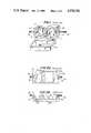
- signal transmission devices connected in series with a CATV cablesuch as tap-off devices, can be arranged as shown in FIG. 1.
- Reference numeral 11is a box-like main housing. Cover 12 is supported on main housing 11 such that the cover can be freely opened and closed with respect to the main housing.
- a recessed chassis 13is disposed in main housing 11. Collars 131 and 132, respectively having input and output connecting terminals 14 and 15, are formed at two ends of chassis 13.
- Input and output connecting terminals 14 and 15are connected to feeder cable 16 to which a plurality of other tap-off devices are connected at various locations along the cable. Input and output connecting terminals 14 and 15 are coupled to each other through a connecting cable 17 disposed along the rear surface of chassis 13, as shown in FIGS. 2(a) and 2(b). Internal electronic units 18 connected to input connecting terminal 14 are arranged on chassis 13.
- the input feeder cable 16must be connected to output feeder cable 16 through a short-circuiting pin or wire (not shown) at the time of repair or replacement of the defective internal unit 18. This results in a time-consuming and cumbersome operation.
- the present inventionhas been made in consideration of the above situation, and has for its object to provide a signal transmission device which allows maintenance and repair procedures to be performed on CATV external control units while minimally disrupting the transmission of CATV signals to subscribers further down the cable.
- a CATV signal transmission deviceconnected in series between a first feeder cable portion and a second feeder cable portion and including a main housing having an input terminal and an output terminal for respectively connecting the main housing to the first and second feeder cable portions, a support member detachably mounted in the main housing and having electronic circuitry mounted thereon, and a coupling member for electrically connecting the first feeder cable portion, the second feeder cable portion, and the electronic circuitry when the support member is mounted in the housing, and for electrically connecting the first feeder cable portion and the second feeder cable portion when the support member is not mounted in said housing.
- FIG. 1is a perspective view illustrating a conventional signal transmission device
- FIGS. 2(a) and 2(b)are a plan view and a sectional view, respectively, of the device shown in FIG. 1;
- FIG. 3is an illustration of part of a CATV system for which the present invention has application
- FIG. 4is a perspective view illustrating a signal transmission device according to an embodiment of the present invention.
- FIG. 5is a perspective view illustrating a detailed structure of the device shown in FIG. 4.
- FIG. 6is a circuit diagram of a portion of the device shown in FIGS. 4 and 5.
- reference numerals 30 and 31denote two CATV feeder cables branched from trunk cables (not shown) connected to a head end.
- Signal transmission device 32is mounted on or adjacent to utility pole 33 and connected to feeder cables 30 and 31.
- Drop cables 35are connected between signal transmission device 32 and one or more subscriber houses 34. Only one subscriber house is shown in FIG. 3 for illustrative convenience. However, in one embodiment, as many as six drop cables can be connected between signal transmission device 32 and as many as six subscriber houses.
- a subscriber processing unit 36 for communicating with signal transmission device 32 to enable a subscriber to select a TV channel for viewingis installed as an indoor unit in each subscriber house 34.
- Signal transmission device 32is connected in series with feeder cables 30 and 31 by connecting the feeder cables to input terminals 301 and 311, respectively, of the signal transmission device and to output terminals 302 and 312 thereof, respectively.
- Feeder cables 30 and 31are subsequently connected to other signal transmission devices (not shown) in like manner.
- second feeder cable 31is provided for system expansion (e.g., to carry additional CATV channels), and is not required to practice the present invention.
- FIG. 4shows the detailed construction of signal transmission device 32.
- a hinged cover 38is mounted on a box-like main housing 37 such that cover 38 can be freely opened or closed with respect to the main housing.
- Feeder cables 30 and 31are connected to input terminals 301 and 311 of main housing 37 and to output terminals 302 and 312 thereof.
- a first conventional directional coupler 39 and a first conventional distributor 40, each associated with feeder cable 30,are located at one end of main housing 37.
- a second conventional directional coupler 41 and a second conventional distributor 42, each associated with feeder cable 31,are located at the other end of main housing 37.
- Chassis 45is detachably mounted in main housing 37.
- Chassis 45includes a plurality of detachably mounted electronic circuit modules, including common control unit 43 and a plurality of subscriber units 44.
- the detachable mounting of the electronic circuit modules to the chassismay be accomplished, for example, by the use of conventional electrical plugs and sockets.
- Distributors 40 and 42are mounted on chassis 45.
- Two terminal blocks 48 and 49are mounted to main housing 37.
- Directional couplers 39 and 41are respectively detachably connected to and mounted on terminal blocks 48 and 49 and distributors 40 and 42.
- Feeder cables 30 and 31are respectively connected to connecting cables 46 and 47 at both ends of main housing 37 in a manner to be described below.
- FIG. 5shows feeder cable 30 at one end of main housing 37.
- the input side of the feeder cable 30is electrically connected to a first terminal 481 of terminal block 48.
- a second terminal 482 of terminal block 48is electrically connected to one end of cable 46.
- the other end of connecting cable 46is connected to the output side of feeder cable 30 at the output end of main housing 37.
- First directional coupler 39is detachably mounted on terminal block 48 by means of plugs 391 and 392 engaging terminal 481 and 482 of terminal block 48.
- First directional coupler 39electrically couples connecting plugs 391, 392, and 393 thereof to the first and second terminals 481 and 482 of terminal block 48, and to first distributor 40, respectively.
- Feeder cable 31is arranged with respect to terminal block 49 (shown in FIG. 4) at the output side of main housing 37 in the same manner as feeder cable 30 is arranged at the input side thereof. Accordingly, a detailed illustration and description of the second connecting arrangement with respect to feeder cable 31 is not shown.
- first and second directional couplers 39 and 41are removed from terminal blocks 48 and 49, respectively, and chassis 45 is removed from main housing 37.
- this interruption of serviceis eliminated by remounting first and second directional couplers 39 and 41 on first and second terminal blocks 48 and 49, respectively.
- the inputs and outputs of feeder cables 30 and 31are respectively electrically connected through directional couplers 39 and 40 and cables 46 and 47, respectively. Subsequently, signals continue to be transmitted further along feeder cables 30 and 31, respectively.
- FIG. 6shows a diagram of the electronic circuitry of the coupler of the invention.
- the circuitry for only feeder cable 30is shown.
- the circuitry for feeder cable 31is identical.
- detachable directional coupler 39having three plugs 391, 392, and 393.
- Plugs 391 and 392connect to terminals 481 and 482 mounted on terminal block 48, and plug 393 connects to terminal 401 of distributor 40 mounted on chassis 45.
- Feeder cable 30 carrying cable TV signals from a head endis attached to terminal 301. Cable TV signals enter directional coupler 391 via terminals 301 and 481.
- Directional coupler 39passes these signals to conventional distributor 40 via plug 393 and terminal 401 for use by the electronic circuitry of the signal transmission device.
- directional coupler 39passes TV signals from plug 391 to terminal 302 via plug 392, terminal 482, and connecting cable 46.
- Feeder cable 30connects to terminal 302 to carry cable TV signals to other signal transmission devices further down the cable.
- directional coupler 39In the event that chassis 45 must be removed from main housing 37 for repair or maintenance, directional coupler 39 is unplugged from terminals 401, 481 and 482, thus breaking the connection between terminals 401, 481, and 482. However, once chassis 45 has been removed, directional coupler 39 can immediately be plugged back into terminals 481 and 482 to re-establish a connection between terminals 301 and 302. Separate jumper wires or other devices are not required to maintain a continuous transmission of signals to other signal transmission devices and other subscribers, located further down the cable. Accordingly, maintenance and repair procedures can be performed on the signal transmission devices while minimally disrupting service to subscribers further down the cable.
Landscapes
- Engineering & Computer Science (AREA)
- Multimedia (AREA)
- Signal Processing (AREA)
- Two-Way Televisions, Distribution Of Moving Picture Or The Like (AREA)
Abstract
Description
Claims (3)
Priority Applications (1)
| Application Number | Priority Date | Filing Date | Title |
|---|---|---|---|
| US06/615,814US4578702A (en) | 1984-05-31 | 1984-05-31 | CATV tap-off unit with detachable directional coupler |
Applications Claiming Priority (1)
| Application Number | Priority Date | Filing Date | Title |
|---|---|---|---|
| US06/615,814US4578702A (en) | 1984-05-31 | 1984-05-31 | CATV tap-off unit with detachable directional coupler |
Publications (1)
| Publication Number | Publication Date |
|---|---|
| US4578702Atrue US4578702A (en) | 1986-03-25 |
Family
ID=24466918
Family Applications (1)
| Application Number | Title | Priority Date | Filing Date |
|---|---|---|---|
| US06/615,814Expired - LifetimeUS4578702A (en) | 1984-05-31 | 1984-05-31 | CATV tap-off unit with detachable directional coupler |
Country Status (1)
| Country | Link |
|---|---|
| US (1) | US4578702A (en) |
Cited By (75)
| Publication number | Priority date | Publication date | Assignee | Title |
|---|---|---|---|---|
| US4755776A (en)* | 1987-03-06 | 1988-07-05 | Broadband Networks, Inc. | Tap device for broadband communications systems |
| US4937599A (en)* | 1988-05-18 | 1990-06-26 | Tempustech, Inc. | Variable configuration time clock |
| US4962447A (en)* | 1989-09-05 | 1990-10-09 | Allan Ullman | Radio frequency signal and power distribution duct |
| US4963966A (en)* | 1989-12-04 | 1990-10-16 | Scientific Atlanta, Inc. | CATV distribution system, especially adapted for off-premises premium channel interdiction |
| US4992627A (en)* | 1989-08-18 | 1991-02-12 | Raychem Corporation | Telecommunications terminal housing and method of enclosing a telecommunications terminal with a minimum clearance opening container |
| WO1991007018A1 (en)* | 1989-11-03 | 1991-05-16 | Raynet Gmbh | Transmission of broadband signals |
| US5045823A (en)* | 1989-08-18 | 1991-09-03 | Smart House Limited Partnership | Terminating scheme for transmitting multiple signals on a coaxial cable to multiple tap outlets |
| US5058198A (en)* | 1989-03-31 | 1991-10-15 | Am Communications, Inc. | Radio frequency tap unit which can be reconfigured with minimal disruption of service |
| US5194947A (en)* | 1990-05-07 | 1993-03-16 | Scientific-Atlanta, Inc. | Apparatus for tapping CATV signals from a cable and for controlling the distribution |
| US5281933A (en)* | 1991-10-29 | 1994-01-25 | North American Philips Corporation | Line power tapping device for cable TV distribution having a moveable module |
| US5461349A (en)* | 1994-10-17 | 1995-10-24 | Simons; Keneth A. | Directional coupler tap and system employing same |
| US5528684A (en)* | 1994-09-02 | 1996-06-18 | Antec Corp. | Coaxial cable interface including security cover for demarcation point |
| US5583931A (en)* | 1993-02-16 | 1996-12-10 | Antec Corp. | Combination telephone network interface and coaxial cable apparatus and coaxial cable module |
| US5583932A (en)* | 1993-02-16 | 1996-12-10 | Antec Corp. | Combination telephone network interface and cable television apparatus |
| US5600717A (en)* | 1993-02-16 | 1997-02-04 | Antec Corp. | Combination telephone network interface and cable television apparatus and cable television module |
| US5606606A (en)* | 1993-02-16 | 1997-02-25 | Antec Corp. | Combination telephone network interface and cable television apparatus and cable television module |
| US5623542A (en)* | 1993-02-16 | 1997-04-22 | Antec Corp. | Combination telephone network interface and cable television apparatus and cable television module |
| EP0739052A3 (en)* | 1995-04-20 | 1997-12-10 | J.E. Thomas Specialties Limited | Circuitry for use with coaxial cable distribution networks |
| US5892653A (en)* | 1995-06-23 | 1999-04-06 | Maspro Denkoh Company, Ltd. | Multi-tap distribution box |
| US5920239A (en)* | 1997-10-07 | 1999-07-06 | Scientific-Atlanta, Inc. | Multiple dwelling unit tap off including an equalizer circuit |
| US5926076A (en)* | 1997-08-07 | 1999-07-20 | Werlatone, Inc. | Adjustable broadband directional coupler |
| US6031300A (en)* | 1997-03-28 | 2000-02-29 | Bell Atlantic Networks Services, Inc. | Bridge tap remover |
| USH1879H (en)* | 1998-03-06 | 2000-10-03 | Scientific-Atlanta, Inc. | Signal equalizer circuit for cable tap |
| US6133939A (en)* | 1999-01-11 | 2000-10-17 | Motorola, Inc. | CATV directional component with signal reversing capability and method |
| US6560778B1 (en)* | 1999-03-29 | 2003-05-06 | Masprodenkoh Kabushikikaisha | Tap device of cable broadcasting system |
| US6570465B2 (en) | 2000-12-01 | 2003-05-27 | Danny Q. Tang | Multi-tap kit for cable television systems |
| US6811430B1 (en) | 2003-11-04 | 2004-11-02 | Tyco Electronics Corporation | Toggle type telecommunications terminal blocks including a travel limit member |
| US20040219815A1 (en)* | 2003-04-30 | 2004-11-04 | Thompson Roy Keller | Toggle type telecommunications terminal blocks |
| US20050171499A1 (en)* | 2004-02-02 | 2005-08-04 | The Procter & Gamble Company | Simple disposable absorbent article |
| US20050199410A1 (en)* | 2004-03-12 | 2005-09-15 | Voon Sze-Moey | Housing having a cable conduit and related systems and methods |
| US7110534B1 (en) | 2000-07-27 | 2006-09-19 | Tyco Electronics Corporation | Terminal blocks and methods for making and breaking connections in a telecommunication conductor |
| US20060264860A1 (en)* | 2005-05-18 | 2006-11-23 | Theodora Beck | Disposable absorbent article having layered containment pockets |
| US20060293638A1 (en)* | 2005-06-23 | 2006-12-28 | Lavon Gary D | Disposable absorbent article having doubled side flaps and backsheet strips |
| US20060293637A1 (en)* | 2005-06-22 | 2006-12-28 | The Procter & Gamble Company | Disposable absorbent article having dual layer barrier cuff strips |
| US7737324B2 (en) | 2005-11-23 | 2010-06-15 | The Procter & Gamble Company | Disposable absorbent article having deployable chassis ears |
| US7857801B2 (en) | 2007-03-23 | 2010-12-28 | The Procter & Gamble Company | Diaper having deployable chassis ears and stretch waistband |
| US8979815B2 (en) | 2012-12-10 | 2015-03-17 | The Procter & Gamble Company | Absorbent articles with channels |
| US9060904B2 (en) | 2007-06-18 | 2015-06-23 | The Procter & Gamble Company | Disposable absorbent article with sealed absorbent core with substantially continuously distributed absorbent particulate polymer material |
| US9066838B2 (en) | 2011-06-10 | 2015-06-30 | The Procter & Gamble Company | Disposable diaper having reduced absorbent core to backsheet gluing |
| US9072634B2 (en) | 2007-06-18 | 2015-07-07 | The Procter & Gamble Company | Disposable absorbent article with substantially continuously distributed absorbent particulate polymer material and method |
| US9216118B2 (en) | 2012-12-10 | 2015-12-22 | The Procter & Gamble Company | Absorbent articles with channels and/or pockets |
| US9216116B2 (en) | 2012-12-10 | 2015-12-22 | The Procter & Gamble Company | Absorbent articles with channels |
| US9375358B2 (en) | 2012-12-10 | 2016-06-28 | The Procter & Gamble Company | Absorbent article with high absorbent material content |
| US9468566B2 (en) | 2011-06-10 | 2016-10-18 | The Procter & Gamble Company | Absorbent structure for absorbent articles |
| US9532910B2 (en) | 2012-11-13 | 2017-01-03 | The Procter & Gamble Company | Absorbent articles with channels and signals |
| US9713556B2 (en) | 2012-12-10 | 2017-07-25 | The Procter & Gamble Company | Absorbent core with high superabsorbent material content |
| US9713557B2 (en) | 2012-12-10 | 2017-07-25 | The Procter & Gamble Company | Absorbent article with high absorbent material content |
| US9763835B2 (en) | 2003-02-12 | 2017-09-19 | The Procter & Gamble Company | Comfortable diaper |
| US9789009B2 (en) | 2013-12-19 | 2017-10-17 | The Procter & Gamble Company | Absorbent articles having channel-forming areas and wetness indicator |
| US9789011B2 (en) | 2013-08-27 | 2017-10-17 | The Procter & Gamble Company | Absorbent articles with channels |
| US9968497B2 (en) | 2014-05-27 | 2018-05-15 | The Procter & Gamble Company | Absorbent core with curved channel-forming areas |
| US9974699B2 (en) | 2011-06-10 | 2018-05-22 | The Procter & Gamble Company | Absorbent core for disposable absorbent articles |
| US9974698B2 (en) | 2014-05-27 | 2018-05-22 | The Procter & Gamble Company | Absorbent core with curved and straight absorbent material areas |
| US9987176B2 (en) | 2013-08-27 | 2018-06-05 | The Procter & Gamble Company | Absorbent articles with channels |
| US10052242B2 (en) | 2014-05-27 | 2018-08-21 | The Procter & Gamble Company | Absorbent core with absorbent material pattern |
| US10071002B2 (en) | 2013-06-14 | 2018-09-11 | The Procter & Gamble Company | Absorbent article and absorbent core forming channels when wet |
| US10130527B2 (en) | 2013-09-19 | 2018-11-20 | The Procter & Gamble Company | Absorbent cores having material free areas |
| US10137039B2 (en) | 2013-12-19 | 2018-11-27 | The Procter & Gamble Company | Absorbent cores having channel-forming areas and C-wrap seals |
| US10149788B2 (en) | 2011-06-10 | 2018-12-11 | The Procter & Gamble Company | Disposable diapers |
| US10292875B2 (en) | 2013-09-16 | 2019-05-21 | The Procter & Gamble Company | Absorbent articles with channels and signals |
| US10322040B2 (en) | 2015-03-16 | 2019-06-18 | The Procter & Gamble Company | Absorbent articles with improved cores |
| US20190207332A1 (en)* | 2018-01-04 | 2019-07-04 | Ppc Broadband, Inc. | Modular circuit board multi-tap |
| US10441481B2 (en) | 2014-05-27 | 2019-10-15 | The Proctre & Gamble Company | Absorbent core with absorbent material pattern |
| US10470948B2 (en) | 2003-02-12 | 2019-11-12 | The Procter & Gamble Company | Thin and dry diaper |
| US10507144B2 (en) | 2015-03-16 | 2019-12-17 | The Procter & Gamble Company | Absorbent articles with improved strength |
| US10543129B2 (en) | 2015-05-29 | 2020-01-28 | The Procter & Gamble Company | Absorbent articles having channels and wetness indicator |
| US10561546B2 (en) | 2011-06-10 | 2020-02-18 | The Procter & Gamble Company | Absorbent structure for absorbent articles |
| US10632029B2 (en) | 2015-11-16 | 2020-04-28 | The Procter & Gamble Company | Absorbent cores having material free areas |
| US10639215B2 (en) | 2012-12-10 | 2020-05-05 | The Procter & Gamble Company | Absorbent articles with channels and/or pockets |
| US10736795B2 (en) | 2015-05-12 | 2020-08-11 | The Procter & Gamble Company | Absorbent article with improved core-to-backsheet adhesive |
| US10842690B2 (en) | 2016-04-29 | 2020-11-24 | The Procter & Gamble Company | Absorbent core with profiled distribution of absorbent material |
| US10958870B2 (en) | 2018-07-26 | 2021-03-23 | Ppc Broadband, Inc. | Cable television multi-tap system |
| US11123240B2 (en) | 2016-04-29 | 2021-09-21 | The Procter & Gamble Company | Absorbent core with transversal folding lines |
| US11207220B2 (en) | 2013-09-16 | 2021-12-28 | The Procter & Gamble Company | Absorbent articles with channels and signals |
| US11233366B2 (en)* | 2020-03-04 | 2022-01-25 | Holland Electronics, Llc | Uninterruptable tap |
Citations (4)
| Publication number | Priority date | Publication date | Assignee | Title |
|---|---|---|---|---|
| US3881160A (en)* | 1974-05-20 | 1975-04-29 | Joseph I Ross | Catv multi-tap distribution box |
| JPS59149748A (en)* | 1983-02-07 | 1984-08-27 | 株式会社東芝 | Power source supplying device |
| US4481641A (en)* | 1982-09-30 | 1984-11-06 | Ford Motor Company | Coaxial cable tap coupler for a data transceiver |
| US4484218A (en)* | 1980-04-30 | 1984-11-20 | The Manitoba Telephone System | Video distribution control system |
- 1984
- 1984-05-31USUS06/615,814patent/US4578702A/ennot_activeExpired - Lifetime
Patent Citations (5)
| Publication number | Priority date | Publication date | Assignee | Title |
|---|---|---|---|---|
| US3881160A (en)* | 1974-05-20 | 1975-04-29 | Joseph I Ross | Catv multi-tap distribution box |
| US3895318A (en)* | 1974-05-20 | 1975-07-15 | Joseph I Ross | Catv multi-tap distribution box with switch |
| US4484218A (en)* | 1980-04-30 | 1984-11-20 | The Manitoba Telephone System | Video distribution control system |
| US4481641A (en)* | 1982-09-30 | 1984-11-06 | Ford Motor Company | Coaxial cable tap coupler for a data transceiver |
| JPS59149748A (en)* | 1983-02-07 | 1984-08-27 | 株式会社東芝 | Power source supplying device |
Cited By (124)
| Publication number | Priority date | Publication date | Assignee | Title |
|---|---|---|---|---|
| US4755776A (en)* | 1987-03-06 | 1988-07-05 | Broadband Networks, Inc. | Tap device for broadband communications systems |
| US4937599A (en)* | 1988-05-18 | 1990-06-26 | Tempustech, Inc. | Variable configuration time clock |
| US5058198A (en)* | 1989-03-31 | 1991-10-15 | Am Communications, Inc. | Radio frequency tap unit which can be reconfigured with minimal disruption of service |
| US5045823A (en)* | 1989-08-18 | 1991-09-03 | Smart House Limited Partnership | Terminating scheme for transmitting multiple signals on a coaxial cable to multiple tap outlets |
| US4992627A (en)* | 1989-08-18 | 1991-02-12 | Raychem Corporation | Telecommunications terminal housing and method of enclosing a telecommunications terminal with a minimum clearance opening container |
| US4962447A (en)* | 1989-09-05 | 1990-10-09 | Allan Ullman | Radio frequency signal and power distribution duct |
| US5363432A (en)* | 1989-11-03 | 1994-11-08 | Raynet Gmbh | Transmission of broadband signals to subscribers using a telecommunications cable |
| WO1991007018A1 (en)* | 1989-11-03 | 1991-05-16 | Raynet Gmbh | Transmission of broadband signals |
| US4963966A (en)* | 1989-12-04 | 1990-10-16 | Scientific Atlanta, Inc. | CATV distribution system, especially adapted for off-premises premium channel interdiction |
| US5194947A (en)* | 1990-05-07 | 1993-03-16 | Scientific-Atlanta, Inc. | Apparatus for tapping CATV signals from a cable and for controlling the distribution |
| US5281933A (en)* | 1991-10-29 | 1994-01-25 | North American Philips Corporation | Line power tapping device for cable TV distribution having a moveable module |
| US5583931A (en)* | 1993-02-16 | 1996-12-10 | Antec Corp. | Combination telephone network interface and coaxial cable apparatus and coaxial cable module |
| US5583932A (en)* | 1993-02-16 | 1996-12-10 | Antec Corp. | Combination telephone network interface and cable television apparatus |
| US5600717A (en)* | 1993-02-16 | 1997-02-04 | Antec Corp. | Combination telephone network interface and cable television apparatus and cable television module |
| US5606606A (en)* | 1993-02-16 | 1997-02-25 | Antec Corp. | Combination telephone network interface and cable television apparatus and cable television module |
| US5623542A (en)* | 1993-02-16 | 1997-04-22 | Antec Corp. | Combination telephone network interface and cable television apparatus and cable television module |
| US5528684A (en)* | 1994-09-02 | 1996-06-18 | Antec Corp. | Coaxial cable interface including security cover for demarcation point |
| US5461349A (en)* | 1994-10-17 | 1995-10-24 | Simons; Keneth A. | Directional coupler tap and system employing same |
| EP0739052A3 (en)* | 1995-04-20 | 1997-12-10 | J.E. Thomas Specialties Limited | Circuitry for use with coaxial cable distribution networks |
| US5892653A (en)* | 1995-06-23 | 1999-04-06 | Maspro Denkoh Company, Ltd. | Multi-tap distribution box |
| US6031300A (en)* | 1997-03-28 | 2000-02-29 | Bell Atlantic Networks Services, Inc. | Bridge tap remover |
| US5926076A (en)* | 1997-08-07 | 1999-07-20 | Werlatone, Inc. | Adjustable broadband directional coupler |
| US5920239A (en)* | 1997-10-07 | 1999-07-06 | Scientific-Atlanta, Inc. | Multiple dwelling unit tap off including an equalizer circuit |
| USH1879H (en)* | 1998-03-06 | 2000-10-03 | Scientific-Atlanta, Inc. | Signal equalizer circuit for cable tap |
| US7086078B1 (en) | 1999-01-11 | 2006-08-01 | General Instrument Corporation | CATV directional component with signal reversing capability and method |
| US6133939A (en)* | 1999-01-11 | 2000-10-17 | Motorola, Inc. | CATV directional component with signal reversing capability and method |
| EP1022815A3 (en)* | 1999-01-11 | 2000-12-20 | General Instrument Corporation | Catv directional component with signal reversing capability and method |
| US6560778B1 (en)* | 1999-03-29 | 2003-05-06 | Masprodenkoh Kabushikikaisha | Tap device of cable broadcasting system |
| US7110534B1 (en) | 2000-07-27 | 2006-09-19 | Tyco Electronics Corporation | Terminal blocks and methods for making and breaking connections in a telecommunication conductor |
| US6570465B2 (en) | 2000-12-01 | 2003-05-27 | Danny Q. Tang | Multi-tap kit for cable television systems |
| US11135096B2 (en) | 2003-02-12 | 2021-10-05 | The Procter & Gamble Company | Comfortable diaper |
| US9763835B2 (en) | 2003-02-12 | 2017-09-19 | The Procter & Gamble Company | Comfortable diaper |
| US11793682B2 (en) | 2003-02-12 | 2023-10-24 | The Procter & Gamble Company | Thin and dry diaper |
| US10660800B2 (en) | 2003-02-12 | 2020-05-26 | The Procter & Gamble Company | Comfortable diaper |
| US10470948B2 (en) | 2003-02-12 | 2019-11-12 | The Procter & Gamble Company | Thin and dry diaper |
| US11234868B2 (en) | 2003-02-12 | 2022-02-01 | The Procter & Gamble Company | Comfortable diaper |
| US6893280B2 (en) | 2003-04-30 | 2005-05-17 | Tyco Electronics Corporation | Toggle type telecommunications terminal blocks |
| US20040219815A1 (en)* | 2003-04-30 | 2004-11-04 | Thompson Roy Keller | Toggle type telecommunications terminal blocks |
| US6811430B1 (en) | 2003-11-04 | 2004-11-02 | Tyco Electronics Corporation | Toggle type telecommunications terminal blocks including a travel limit member |
| US7736351B2 (en) | 2004-02-02 | 2010-06-15 | The Procter & Gamble Company | Simple disposable absorbent article |
| US20050171499A1 (en)* | 2004-02-02 | 2005-08-04 | The Procter & Gamble Company | Simple disposable absorbent article |
| US20100241097A1 (en)* | 2004-02-02 | 2010-09-23 | Pankaj Nigam | Simple disposable absorbent article |
| US7430124B2 (en)* | 2004-03-12 | 2008-09-30 | Hewlett-Packard Development Company, L.P. | Housing having a cable conduit and related systems and methods |
| US20050199410A1 (en)* | 2004-03-12 | 2005-09-15 | Voon Sze-Moey | Housing having a cable conduit and related systems and methods |
| US20060264860A1 (en)* | 2005-05-18 | 2006-11-23 | Theodora Beck | Disposable absorbent article having layered containment pockets |
| US7763004B2 (en) | 2005-05-18 | 2010-07-27 | The Procter & Gamble Company | Disposable absorbent article having layered containment pockets |
| US20100125263A1 (en)* | 2005-06-22 | 2010-05-20 | Gary Dean Lavon | Disposable absorbent article having dual layer barrier cuff strips |
| US20060293637A1 (en)* | 2005-06-22 | 2006-12-28 | The Procter & Gamble Company | Disposable absorbent article having dual layer barrier cuff strips |
| US7695463B2 (en) | 2005-06-22 | 2010-04-13 | The Procter & Gamble Company | Disposable absorbent article having dual layer barrier cuff strips |
| US20060293638A1 (en)* | 2005-06-23 | 2006-12-28 | Lavon Gary D | Disposable absorbent article having doubled side flaps and backsheet strips |
| US7618404B2 (en) | 2005-06-23 | 2009-11-17 | The Procter & Gamble Company | Disposable absorbent article having doubled side flaps and backsheet strips |
| US7737324B2 (en) | 2005-11-23 | 2010-06-15 | The Procter & Gamble Company | Disposable absorbent article having deployable chassis ears |
| US7857801B2 (en) | 2007-03-23 | 2010-12-28 | The Procter & Gamble Company | Diaper having deployable chassis ears and stretch waistband |
| US9060904B2 (en) | 2007-06-18 | 2015-06-23 | The Procter & Gamble Company | Disposable absorbent article with sealed absorbent core with substantially continuously distributed absorbent particulate polymer material |
| US9072634B2 (en) | 2007-06-18 | 2015-07-07 | The Procter & Gamble Company | Disposable absorbent article with substantially continuously distributed absorbent particulate polymer material and method |
| US9241845B2 (en) | 2007-06-18 | 2016-01-26 | The Procter & Gamble Company | Disposable absorbent article with sealed absorbent core with substantially continuously distributed absorbent particulate polymer material |
| US9974699B2 (en) | 2011-06-10 | 2018-05-22 | The Procter & Gamble Company | Absorbent core for disposable absorbent articles |
| US11911250B2 (en) | 2011-06-10 | 2024-02-27 | The Procter & Gamble Company | Absorbent structure for absorbent articles |
| US9649232B2 (en) | 2011-06-10 | 2017-05-16 | The Procter & Gamble Company | Disposable diaper having reduced absorbent core to backsheet gluing |
| US10517777B2 (en) | 2011-06-10 | 2019-12-31 | The Procter & Gamble Company | Disposable diaper having first and second absorbent structures and channels |
| US9066838B2 (en) | 2011-06-10 | 2015-06-30 | The Procter & Gamble Company | Disposable diaper having reduced absorbent core to backsheet gluing |
| US9468566B2 (en) | 2011-06-10 | 2016-10-18 | The Procter & Gamble Company | Absorbent structure for absorbent articles |
| US9173784B2 (en) | 2011-06-10 | 2015-11-03 | The Procter & Gamble Company | Disposable diaper having reduced absorbent core to backsheet gluing |
| US10149788B2 (en) | 2011-06-10 | 2018-12-11 | The Procter & Gamble Company | Disposable diapers |
| US10893987B2 (en) | 2011-06-10 | 2021-01-19 | The Procter & Gamble Company | Disposable diapers with main channels and secondary channels |
| US11135105B2 (en) | 2011-06-10 | 2021-10-05 | The Procter & Gamble Company | Absorbent structure for absorbent articles |
| US10130525B2 (en) | 2011-06-10 | 2018-11-20 | The Procter & Gamble Company | Absorbent structure for absorbent articles |
| US10561546B2 (en) | 2011-06-10 | 2020-02-18 | The Procter & Gamble Company | Absorbent structure for absorbent articles |
| US11110011B2 (en) | 2011-06-10 | 2021-09-07 | The Procter & Gamble Company | Absorbent structure for absorbent articles |
| US11602467B2 (en) | 2011-06-10 | 2023-03-14 | The Procter & Gamble Company | Absorbent structure for absorbent articles |
| US9532910B2 (en) | 2012-11-13 | 2017-01-03 | The Procter & Gamble Company | Absorbent articles with channels and signals |
| US10449097B2 (en) | 2012-11-13 | 2019-10-22 | The Procter & Gamble Company | Absorbent articles with channels and signals |
| US10966885B2 (en) | 2012-12-10 | 2021-04-06 | The Procter & Gamble Company | Absorbent article with high absorbent material content |
| US9216116B2 (en) | 2012-12-10 | 2015-12-22 | The Procter & Gamble Company | Absorbent articles with channels |
| US9216118B2 (en) | 2012-12-10 | 2015-12-22 | The Procter & Gamble Company | Absorbent articles with channels and/or pockets |
| US10022280B2 (en) | 2012-12-10 | 2018-07-17 | The Procter & Gamble Company | Absorbent article with high absorbent material content |
| US8979815B2 (en) | 2012-12-10 | 2015-03-17 | The Procter & Gamble Company | Absorbent articles with channels |
| US12016761B2 (en) | 2012-12-10 | 2024-06-25 | The Procter & Gamble Company | Absorbent article with high absorbent material content |
| US9375358B2 (en) | 2012-12-10 | 2016-06-28 | The Procter & Gamble Company | Absorbent article with high absorbent material content |
| US12274609B2 (en) | 2012-12-10 | 2025-04-15 | The Procter & Gamble Company | Absorbent article with high absorbent material content |
| US9713557B2 (en) | 2012-12-10 | 2017-07-25 | The Procter & Gamble Company | Absorbent article with high absorbent material content |
| US9713556B2 (en) | 2012-12-10 | 2017-07-25 | The Procter & Gamble Company | Absorbent core with high superabsorbent material content |
| US10639215B2 (en) | 2012-12-10 | 2020-05-05 | The Procter & Gamble Company | Absorbent articles with channels and/or pockets |
| US11273086B2 (en) | 2013-06-14 | 2022-03-15 | The Procter & Gamble Company | Absorbent article and absorbent core forming channels when wet |
| US10071002B2 (en) | 2013-06-14 | 2018-09-11 | The Procter & Gamble Company | Absorbent article and absorbent core forming channels when wet |
| US9789011B2 (en) | 2013-08-27 | 2017-10-17 | The Procter & Gamble Company | Absorbent articles with channels |
| US10765567B2 (en) | 2013-08-27 | 2020-09-08 | The Procter & Gamble Company | Absorbent articles with channels |
| US11406544B2 (en) | 2013-08-27 | 2022-08-09 | The Procter & Gamble Company | Absorbent articles with channels |
| US11612523B2 (en) | 2013-08-27 | 2023-03-28 | The Procter & Gamble Company | Absorbent articles with channels |
| US9987176B2 (en) | 2013-08-27 | 2018-06-05 | The Procter & Gamble Company | Absorbent articles with channels |
| US11759376B2 (en) | 2013-08-27 | 2023-09-19 | The Procter & Gamble Company | Absorbent articles with channels |
| US10736794B2 (en) | 2013-08-27 | 2020-08-11 | The Procter & Gamble Company | Absorbent articles with channels |
| US10335324B2 (en) | 2013-08-27 | 2019-07-02 | The Procter & Gamble Company | Absorbent articles with channels |
| US11957551B2 (en) | 2013-09-16 | 2024-04-16 | The Procter & Gamble Company | Absorbent articles with channels and signals |
| US11207220B2 (en) | 2013-09-16 | 2021-12-28 | The Procter & Gamble Company | Absorbent articles with channels and signals |
| US10292875B2 (en) | 2013-09-16 | 2019-05-21 | The Procter & Gamble Company | Absorbent articles with channels and signals |
| US11944526B2 (en) | 2013-09-19 | 2024-04-02 | The Procter & Gamble Company | Absorbent cores having material free areas |
| US10130527B2 (en) | 2013-09-19 | 2018-11-20 | The Procter & Gamble Company | Absorbent cores having material free areas |
| US11154437B2 (en) | 2013-09-19 | 2021-10-26 | The Procter & Gamble Company | Absorbent cores having material free areas |
| US11191679B2 (en) | 2013-12-19 | 2021-12-07 | The Procter & Gamble Company | Absorbent articles having channel-forming areas and wetness indicator |
| US10828206B2 (en) | 2013-12-19 | 2020-11-10 | Procter & Gamble Company | Absorbent articles having channel-forming areas and wetness indicator |
| US9789009B2 (en) | 2013-12-19 | 2017-10-17 | The Procter & Gamble Company | Absorbent articles having channel-forming areas and wetness indicator |
| US12226292B2 (en) | 2013-12-19 | 2025-02-18 | The Procter & Gamble Company | Absorbent articles having channel-forming areas and wetness indicator |
| US10675187B2 (en) | 2013-12-19 | 2020-06-09 | The Procter & Gamble Company | Absorbent articles having channel-forming areas and wetness indicator |
| US10137039B2 (en) | 2013-12-19 | 2018-11-27 | The Procter & Gamble Company | Absorbent cores having channel-forming areas and C-wrap seals |
| US9968497B2 (en) | 2014-05-27 | 2018-05-15 | The Procter & Gamble Company | Absorbent core with curved channel-forming areas |
| US9974698B2 (en) | 2014-05-27 | 2018-05-22 | The Procter & Gamble Company | Absorbent core with curved and straight absorbent material areas |
| US10441481B2 (en) | 2014-05-27 | 2019-10-15 | The Proctre & Gamble Company | Absorbent core with absorbent material pattern |
| US10052242B2 (en) | 2014-05-27 | 2018-08-21 | The Procter & Gamble Company | Absorbent core with absorbent material pattern |
| US10507144B2 (en) | 2015-03-16 | 2019-12-17 | The Procter & Gamble Company | Absorbent articles with improved strength |
| US10322040B2 (en) | 2015-03-16 | 2019-06-18 | The Procter & Gamble Company | Absorbent articles with improved cores |
| US11918445B2 (en) | 2015-05-12 | 2024-03-05 | The Procter & Gamble Company | Absorbent article with improved core-to-backsheet adhesive |
| US10736795B2 (en) | 2015-05-12 | 2020-08-11 | The Procter & Gamble Company | Absorbent article with improved core-to-backsheet adhesive |
| US11497657B2 (en) | 2015-05-29 | 2022-11-15 | The Procter & Gamble Company | Absorbent articles having channels and wetness indicator |
| US10543129B2 (en) | 2015-05-29 | 2020-01-28 | The Procter & Gamble Company | Absorbent articles having channels and wetness indicator |
| US10632029B2 (en) | 2015-11-16 | 2020-04-28 | The Procter & Gamble Company | Absorbent cores having material free areas |
| US11123240B2 (en) | 2016-04-29 | 2021-09-21 | The Procter & Gamble Company | Absorbent core with transversal folding lines |
| US10842690B2 (en) | 2016-04-29 | 2020-11-24 | The Procter & Gamble Company | Absorbent core with profiled distribution of absorbent material |
| US10784597B2 (en)* | 2018-01-04 | 2020-09-22 | Ppc Broadband, Inc. | Modular circuit board multi-tap |
| US20190207332A1 (en)* | 2018-01-04 | 2019-07-04 | Ppc Broadband, Inc. | Modular circuit board multi-tap |
| US11522304B2 (en) | 2018-01-04 | 2022-12-06 | Ppc Broadband, Inc. | Modular circuit board multi-tap |
| US10958870B2 (en) | 2018-07-26 | 2021-03-23 | Ppc Broadband, Inc. | Cable television multi-tap system |
| US12132246B2 (en) | 2018-07-26 | 2024-10-29 | Ppc Broadband, Inc. | Cable television multi-tap system comprising a tap housing having a removable access cover allowing at least replacement of a directional coupler with another directional coupler |
| US11233366B2 (en)* | 2020-03-04 | 2022-01-25 | Holland Electronics, Llc | Uninterruptable tap |
Similar Documents
| Publication | Publication Date | Title |
|---|---|---|
| US4578702A (en) | CATV tap-off unit with detachable directional coupler | |
| US6393607B1 (en) | AC port device for cable television tap | |
| US5130893A (en) | Signal distribution system | |
| US7086078B1 (en) | CATV directional component with signal reversing capability and method | |
| US7339111B2 (en) | System handling video, control signals and power | |
| US5599190A (en) | Communication wiring system including a reconfigurable outlet assembly | |
| US5909154A (en) | Broadband signal tap with continuity bridge | |
| US5482469A (en) | Dual monitor self-contained six port digital signal cross-connect module | |
| US20020097105A1 (en) | Multi-circuit signal transformer | |
| GR3001245T3 (en) | Divider device, particularly for the main divider of telecommunication installations | |
| US5434610A (en) | Methods and apparatus for the reconfiguration of cable television systems | |
| US20090265745A1 (en) | Reversible Faceplate Terminal Adapter Which Changes Signal Flow Direction | |
| US6791213B2 (en) | Reconfigurable signal distribution system | |
| US4542372A (en) | Data distribution apparatus | |
| MXPA04008686A (en) | A measurement arrangement and telecommunications assembly. | |
| EP0895354A2 (en) | Voltage-controlled oscillator | |
| US4575840A (en) | Telephone line access device for main distribution frame | |
| US6262636B1 (en) | Apparatus for reversing direction of signal flow in a broadband signal tap | |
| US20030021092A1 (en) | Faceted extended interface module | |
| US5920239A (en) | Multiple dwelling unit tap off including an equalizer circuit | |
| EP1135923B1 (en) | A method for the distribution and transfer of communication and multimedia signals, as well as a signal distribution arrangement for the transfer of the communication and multimedia signals | |
| US6078507A (en) | Patch panel with incorporated distribution amplifiers | |
| US6504874B1 (en) | Arrangement for digital transmission of information across wires | |
| JP3057193B2 (en) | MDF device | |
| KR200355070Y1 (en) | Tap-off for catv |
Legal Events
| Date | Code | Title | Description |
|---|---|---|---|
| AS | Assignment | Owner name:AMERICAN TELEVISION & COMMUNICATIONS CORPORATION, Free format text:ASSIGNMENT OF ASSIGNORS INTEREST.;ASSIGNOR:CAMPBELL, WALLACE S. III;REEL/FRAME:004267/0421 Effective date:19840529 Owner name:AMERICAN TELEVISION & COMMUNICATIONS CORPORATION,C Free format text:ASSIGNMENT OF ASSIGNORS INTEREST;ASSIGNOR:CAMPBELL, WALLACE S. III;REEL/FRAME:004267/0421 Effective date:19840529 | |
| STCF | Information on status: patent grant | Free format text:PATENTED CASE | |
| FPAY | Fee payment | Year of fee payment:4 | |
| AS | Assignment | Owner name:TIME WARNER ENTERTAINMENT COMPANY L.P., NEW YORK Free format text:ASSIGNMENT OF ASSIGNORS INTEREST.;ASSIGNOR:AMERICAN TELEVISION AND COMMUNICATIONS CORPORATION, A CORP. OF DE;REEL/FRAME:006243/0645 Effective date:19920630 | |
| FEPP | Fee payment procedure | Free format text:PAYOR NUMBER ASSIGNED (ORIGINAL EVENT CODE: ASPN); ENTITY STATUS OF PATENT OWNER: LARGE ENTITY | |
| FPAY | Fee payment | Year of fee payment:8 | |
| FPAY | Fee payment | Year of fee payment:12 |