US4578060A - Wound drainage device - Google Patents
Wound drainage deviceDownload PDFInfo
- Publication number
- US4578060A US4578060AUS06/515,504US51550483AUS4578060AUS 4578060 AUS4578060 AUS 4578060AUS 51550483 AUS51550483 AUS 51550483AUS 4578060 AUS4578060 AUS 4578060A
- Authority
- US
- United States
- Prior art keywords
- housing
- bellows
- container
- fluids
- variable force
- Prior art date
- Legal status (The legal status is an assumption and is not a legal conclusion. Google has not performed a legal analysis and makes no representation as to the accuracy of the status listed.)
- Expired - Lifetime
Links
Images


Classifications
- A—HUMAN NECESSITIES
- A61—MEDICAL OR VETERINARY SCIENCE; HYGIENE
- A61M—DEVICES FOR INTRODUCING MEDIA INTO, OR ONTO, THE BODY; DEVICES FOR TRANSDUCING BODY MEDIA OR FOR TAKING MEDIA FROM THE BODY; DEVICES FOR PRODUCING OR ENDING SLEEP OR STUPOR
- A61M1/00—Suction or pumping devices for medical purposes; Devices for carrying-off, for treatment of, or for carrying-over, body-liquids; Drainage systems
- A61M1/64—Containers with integrated suction means
- A61M1/68—Containers incorporating a flexible member creating suction
Definitions
- This inventionrelates to suction devices and more particularly to an improved device for automatic removal of fluids from a wound.
- Canadian Pat. No. 879,849discloses a device which includes a container with a concertina-pleated wall that can be expanded to increase the volume of the container.
- a detachable external spring bowserves to extend the pleated wall thereby causing suction within the container.
- the concertina-pleated wallsare consecutively numbered to permit measurement of the fluid collected when the container is in an open extended position.
- the evacuator disclosed in U.S. Pat. No. 3,376,868includes a compressible container made from resilient elastomeric material whose memory causes the walls to return to an uncompressed state.
- a valve turret on the top of the containerprovides both an inlet and a vent opening which is sealable by means such as a plug or a resilient diaphragm connected to the top.
- U.S. Pat. No. 3,774,611discloses a contamination free evacuator including a compressible-expandable container having an inlet and an outlet region, and a fluid stabilizer inside the container.
- a contamination free evacuatoris also disclosed in U.S. Pat. No. 3,779,243 which includes a compressible and expandable evacuator bag having both a drain inlet and an exhaust outlet fromed in the bag.
- the latterfurther includes a magnetic one-way exhaust valve which prevents the contamination of the bag by closing upon completion of exhausting fluids from the bag.
- the device of the present inventionis designed to provide a substantially constant negative pressure throughout the range of drawing and collecting body fluids from a wound into the device. Also the device is available to the user in a preactivated state. The device thus avoids the need for the handler to discharge the air within the device as is found to be the case with almost all of the apparatus of the above discussed prior art. Additional ease of operation is provided herein in that this device permits one hand operation freeing the handler to attend to additional matters while simultaneously activating the device. The device is also designed to permit alternatively either total discard or evacuation of the collected fluids and reactivation for subsequent reuse.
- the devicecomprises an elongated housing having at least one end wall at one end thereof, said end wall having an opening, an airtight and watertight resilient elongated bellows disposed within the housing, the bellows being collapsible and expandable and having an upper and a lower end, means for communicating with the interior of the bellows, means for maintaining the upper end of the bellows adjacent said end wall of the housing, means for collapsing the bellows within the housing, and variable force means for automatically expanding the bellows from its collapsed state such that the combined resultant force of the variable forces provided by the bellows and the variable force expansion means allows for the creation of a substantially constant level of negative pressure within the bellows so as to provide for the removal of fluids from the wound at a substantially constant level of suction substantially throughout the range of evacuation.
- the first positionis suitably chosen so that the bellows is substantially fully collapsed when the tab is at the first position.
- the variable force spring assemblypreferably is a ribbon spring having a free end extending along the longitudinal axis of the housing and being attached to the bellows. Release of the tab from its respective cutout allows the ribbon spring to draw the collar toward the other end of the housing so as to expand the bellows and produce a negative pressure therein.
- the ribbon springe.g., a negator spring, is programmed so that its restoring force combined with that of the bellows provides a substantially constant force of suction of fluid into the bellows.
- the housingis substantially rigid and is formed of a transparent plastic so as to permit visible inspection of the operation of the bellows, the collar, and the ribbon spring within the housing.
- the bellowsis formed of a transparent plastic so as to permit visible inspection of the fluid withdrawn therein from the wound. Graduations are provided on the housing so as to permit the measurement of fluid withdrawn therein from the wound. In addition, textured, e.g., frosted predetermined areas are provided on the housing to permit selective imprinting of desired information thereon.
- the bellowsincludes an integral member extending outwardly from the end wall of the housing.
- the integral memberis dimensioned and configured so as to pass through the second opening out from the housing such that the upper end of the bellows is maintained in a secured relationship with the end wall of the housing.
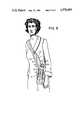
- Meansare also provided, preferably in the form of a strap passing through a C-clip on the housing for portably supporting same on the body as a self-contained portable unit.
- FIG. 2is an exploded view of an alternative embodiment of the device of FIG. 1.
- FIG. 3is an end view of the device of FIG. 1 taken in the direction of arrow "A".
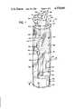
- FIG. 5is a side elevational view partially in cross-section of the device of FIG. 1 taken in the direction of line A--A of FIG. 1.
- the bottommost flangeis positioned above the upper end 32 of bellows 14 a distance at least slightly larger than the thickness of end wall 22. Hence, the bottommost flange after passing through hole 24 rests against the upper surface of end wall 22 and does not allow the tube 42 to be withdrawn back through the opening 24. In this manner the upper end 32 of the bellows 14 is kept adjacent the end wall 22. The bellows 14 can then be expanded downward toward the lower end of the housing 12.
- assembly of the device 10is accomplished by inserting the above-mentioned components bellows 14 first through the open end of housing 12 so that the tabs 50 are slidably engaged within slits 26.
- the bellows 14is inserted tube 42 first. Once the bottommost flange of the tube 42 passes through the end wall opening 24, the tube 42 cannot pass back into the housing 12.
- the upper end of the bellows 14is thereby kept adjacent the cover 22 and thus serves as a fixed point from which the bellows 14 can expand by means of the force of spring assembly 20 combined with the restoring force of the resilient bellows 14 itself.
- the coiled spring portion 68can be kept coiled within a pocket 78 defined within an annular wall 80 formed integrally with the bottom end wall 66.
- the free portion 70 of spring assembly 20passes through an opening 82 formed in annular wall 80.
- the bottom end wall 66is integrally formed both with the base 18 and housing 12 in two halves joined at seam 84 as shown in FIG. 1.
- the tabs 50 according to FIG. 1have an outwardly projecting member 86 against which the user's fingers can rest in order to aid in compressing the bellows.
- the tube 42 as shown in FIG. 5is secured to the upper end wall 22 by a key shaped member 88 which passes through a like dimensioned notch in the upper end wall 22. By slightly twisting the key shaped member 88, the tube 42 is locked in place.
- the assembly of the device 10may be finalized by the bonding of separate structural components together.
- the ring 30 of the other end of housing 12is glued into the groove 72 on the upperside of the integral base top end wall 60.
- the cross bar 48can also be glued into its cutouts (not shown) in the collar ring 46 of slide collar 16.
- the end walls 22 and 60, and tube 42can be constructed separately from their respective structures and glued thereto.
- ultrasonic weldingis used to attach the ring 30 to the groove 72.
- Assembly of the device 10is not limited to gluing and ultrasonic welding but may be accomplished by any other conventional means known and appreciated by those skilled in such arts including but not limited to mechanical means such as screws.
- the embodiment of FIG. 1can be assembled by installing the bellows 14 and spring assembly 20 within one half of the integral housing 12 and base 18 and thereafter securing the second half thereto along seam 84.
- the housing 12will be made of a transparent plastic and will have etched graduations 90 thereon as shown in FIGS. 1 and 2. The user will therefore be able to visibly inspect the proper operation of the device 10. Additionally he can measure the amount of fluid collected upon holding the bellows upper end 32 upside down and comparing the fluid level against the graduations 90.
- the duct 106is sealed with seal cap 112 so that fluid from a wound may enter the bellows 14 through tubing 118, duct 108 and one-way valve 110 which prevents any fluid within the bellows 14 from returning to the wound.
- the cap on the remaining Y connector ductpermits evacuation of fluid from the bellows 14 by advancing the tabs 50 toward the first position ("B") thereby compressing the bellows 14.
- the fluidmay be totally evacuated from the bellows 14 which then is ready for continued use.
- the bellows 14can be partially evacuated into another container to permit immediate transfer of the fluid for study, e.g., in a pathology laboratory, without disrupting the hookup of the device 10 for further removal of fluid from a wound or the like.
Landscapes
- Health & Medical Sciences (AREA)
- Heart & Thoracic Surgery (AREA)
- Vascular Medicine (AREA)
- Engineering & Computer Science (AREA)
- Anesthesiology (AREA)
- Biomedical Technology (AREA)
- Hematology (AREA)
- Life Sciences & Earth Sciences (AREA)
- Animal Behavior & Ethology (AREA)
- General Health & Medical Sciences (AREA)
- Public Health (AREA)
- Veterinary Medicine (AREA)
- External Artificial Organs (AREA)
Abstract
Description
Claims (27)
Priority Applications (1)
| Application Number | Priority Date | Filing Date | Title |
|---|---|---|---|
| US06/515,504US4578060A (en) | 1983-07-20 | 1983-07-20 | Wound drainage device |
Applications Claiming Priority (1)
| Application Number | Priority Date | Filing Date | Title |
|---|---|---|---|
| US06/515,504US4578060A (en) | 1983-07-20 | 1983-07-20 | Wound drainage device |
Publications (1)
| Publication Number | Publication Date |
|---|---|
| US4578060Atrue US4578060A (en) | 1986-03-25 |
Family
ID=24051638
Family Applications (1)
| Application Number | Title | Priority Date | Filing Date |
|---|---|---|---|
| US06/515,504Expired - LifetimeUS4578060A (en) | 1983-07-20 | 1983-07-20 | Wound drainage device |
Country Status (1)
| Country | Link |
|---|---|
| US (1) | US4578060A (en) |
Cited By (87)
| Publication number | Priority date | Publication date | Assignee | Title |
|---|---|---|---|---|
| US4664652A (en)* | 1985-02-07 | 1987-05-12 | Snyder Laboratories, Inc. | Wound evacuator |
| US4702397A (en)* | 1984-09-18 | 1987-10-27 | Infusion Systems Corporation | Pressurized fluid dispenser |
| US4781689A (en)* | 1986-11-13 | 1988-11-01 | Andrew Sealfon | Spring-operated liquid-dispensing device |
| US4850807A (en)* | 1987-06-16 | 1989-07-25 | Frantz Medical Development Ltd. | Disposable cassette for fluid delivery pump systems |
| EP0245876A3 (en)* | 1986-05-16 | 1989-08-09 | Testa-Laboratorium A/S | Aspirator |
| US4950247A (en)* | 1986-09-02 | 1990-08-21 | Rosenblatt/Ima Invention Enterprises | Aspirator for collection of bodily fluids including improved safety and efficiency elements |
| US4979944A (en)* | 1989-08-21 | 1990-12-25 | The Pullman Company | Surgical vacuum evacuation device |
| US5071409A (en)* | 1990-01-12 | 1991-12-10 | Lior Rosenberg | Vacuum device particularly useful for draining wounds |
| US5098386A (en)* | 1991-05-17 | 1992-03-24 | Smith Ina L | Infant nasal suction apparatus |
| US5149325A (en)* | 1991-02-25 | 1992-09-22 | Baxter International Inc. | Vacuum system for auto transfusion device |
| US5223228A (en)* | 1991-02-25 | 1993-06-29 | Baxter International Inc. | Tray for autotransfusion module |
| US5237309A (en)* | 1987-07-20 | 1993-08-17 | Frantz Medical Development, Ltd. | Pump cassette and method of pumping |
| USD339194S (en) | 1991-02-25 | 1993-09-07 | Baxter International Inc. | Pressure control module |
| US5382244A (en)* | 1991-02-25 | 1995-01-17 | Baxter International Inc. | Stand alone control module |
| EP0655253A1 (en)* | 1993-10-26 | 1995-05-31 | Daiken Iki Co. Ltd. | Fluid aspiration-collection apparatus |
| US5496299A (en)* | 1994-09-21 | 1996-03-05 | C. R. Bard, Inc. | Suction reservoir |
| US5588958A (en)* | 1994-09-21 | 1996-12-31 | C. R. Bard, Inc. | Closed wound orthopaedic drainage and autotransfusion system |
| WO1997023250A1 (en)* | 1995-12-22 | 1997-07-03 | Science Incorporated | Fluid dispenser with fill adapter |
| US6770061B2 (en) | 2000-12-19 | 2004-08-03 | Hill-Rom Services, Inc. | Low exposure waste disposal suction system and associated method |
| US20050080387A1 (en)* | 2001-11-29 | 2005-04-14 | Yoshifumi Matsuura | Discharging implement for medical care |
| US20060287584A1 (en)* | 2005-06-16 | 2006-12-21 | Javier Garcia-Bengochia | Surgical retractor extensions |
| GB2431351A (en)* | 2005-03-16 | 2007-04-25 | Ind Ltd Ak | Wound dressing vacuum system and vacuum regulator |
| US20070129694A1 (en)* | 2003-06-05 | 2007-06-07 | Opie John C | Fluid evacuator system |
| US20080004549A1 (en)* | 2006-06-12 | 2008-01-03 | Anderson Paul J | Negative pressure wound treatment device, and methods |
| US20080082059A1 (en)* | 2006-09-28 | 2008-04-03 | David Fink | Portable wound therapy system |
| US20080108977A1 (en)* | 2006-10-13 | 2008-05-08 | Heaton Keith P | Reduced pressure delivery system having a manually-activated pump for providing treatment to low-severity wounds |
| US20080200905A1 (en)* | 2007-02-09 | 2008-08-21 | Keith Patrick Heaton | System and method for applying reduced pressure at a tissue site |
| US20090012482A1 (en)* | 2007-03-14 | 2009-01-08 | Pinto Moshe | Devices and methods for application of reduced pressure therapy |
| US20090012485A1 (en)* | 2007-03-23 | 2009-01-08 | Michaels Thomas L | Fluid collection and disposal system having interchangeable collection and other features and methods relating thereto |
| US20090254066A1 (en)* | 2006-10-13 | 2009-10-08 | Keith Patrick Heaton | Reduced pressure indicator for a reduced pressure source |
| US20090259203A1 (en)* | 2007-10-11 | 2009-10-15 | Dean Hu | Closed incision negative pressure wound therapy device and methods of use |
| US20090275922A1 (en)* | 2008-05-02 | 2009-11-05 | Richard Daniel John Coulthard | Manually-actuated reduced pressure treatment system having regulated pressure capabilities |
| US20100030166A1 (en)* | 2008-07-11 | 2010-02-04 | Aidan Marcus Tout | Manually-actuated, reduced-pressure systems for treating wounds |
| US20100042021A1 (en)* | 2008-02-14 | 2010-02-18 | Spiracur, Inc. | Devices and methods for treatment of damaged tissue |
| US20100056995A1 (en)* | 2008-09-03 | 2010-03-04 | Kriesel Marshall S | Two part fluid dispenser |
| US20100137775A1 (en)* | 2008-11-25 | 2010-06-03 | Spiracur Inc. | Device for delivery of reduced pressure to body surfaces |
| US20100174250A1 (en)* | 2009-01-07 | 2010-07-08 | Spiracur Inc. | Reduced pressure therapy of the sacral region |
| US20100228205A1 (en)* | 2009-03-04 | 2010-09-09 | Spiracur Inc. | Devices and methods to apply alternating level of reduced pressure to tissue |
| USD629502S1 (en) | 2009-02-17 | 2010-12-21 | Spiracur Inc. | Reduced pressure therapy device |
| US20110015594A1 (en)* | 2009-04-10 | 2011-01-20 | Dean Hu | Methods and Devices for Applying Closed Incision Negative Pressure Wound Therapy |
| US20110106026A1 (en)* | 2009-04-10 | 2011-05-05 | Kenneth Wu | Methods and devices for applying closed incision negative pressure wound therapy |
| US20110118680A1 (en)* | 2009-07-15 | 2011-05-19 | Cardinal Health, Inc. | Fluid collection and disposal system and related methods |
| US20110178482A1 (en)* | 2007-03-23 | 2011-07-21 | Cardinal Health, Inc. | Fluid collection and disposal system and related methods |
| US20120071845A1 (en)* | 2010-08-10 | 2012-03-22 | Dean Hu | Controlled negative pressure apparatus and absorbency mechanism |
| USD672452S1 (en)* | 2010-07-09 | 2012-12-11 | Research Medical Pty Ltd | Wound drainage flow control device |
| USD686724S1 (en) | 2009-02-17 | 2013-07-23 | Spiracur Inc. | Reduced pressure therapy device |
| US8753322B2 (en) | 2010-08-10 | 2014-06-17 | Spiracur Inc. | Controlled negative pressure apparatus and alarm mechanism |
| US8834452B2 (en) | 2008-05-21 | 2014-09-16 | Smith & Nephew, Inc. | Wound therapy system and related methods therefor |
| US8834451B2 (en) | 2002-10-28 | 2014-09-16 | Smith & Nephew Plc | In-situ wound cleansing apparatus |
| US8882678B2 (en) | 2009-03-13 | 2014-11-11 | Atrium Medical Corporation | Pleural drainage system and method of use |
| US8998866B2 (en) | 2010-07-02 | 2015-04-07 | Smith & Nephew Plc | Provision of wound filler |
| EP2334368A4 (en)* | 2008-09-03 | 2015-05-06 | Marshall S Kriesel | TWO-PART FLUID DISPENSER |
| US9198801B2 (en) | 2004-04-05 | 2015-12-01 | Bluesky Medical Group, Inc. | Flexible reduced pressure treatment appliance |
| US20160106891A1 (en)* | 2013-06-19 | 2016-04-21 | Nuangle Medical (Pty) Ltd | Fluid drainage container |
| US20160177976A1 (en)* | 2013-08-27 | 2016-06-23 | Gustav Magenwirth Gmbh & Co. | Master Cylinder Fitting |
| US9427505B2 (en) | 2012-05-15 | 2016-08-30 | Smith & Nephew Plc | Negative pressure wound therapy apparatus |
| WO2017040021A1 (en) | 2015-09-01 | 2017-03-09 | Kci Licensing, Inc. | Reduced pressure tissue therapy device |
| DE102015219775A1 (en)* | 2015-10-13 | 2017-04-13 | MedicPart Plus GmbH | Manually operated suction device for absorbing body fluids, suction attachment for such a suction device and set for absorbing body fluids with a suction device and a suction attachment |
| USD786420S1 (en)* | 2014-11-26 | 2017-05-09 | Nuangle Medical (Pty) Ltd | Fluid drainage device |
| CN107583114A (en)* | 2017-09-25 | 2018-01-16 | 田玲玲 | A kind of Emergence fast and safely sputum aspirator |
| CN107666917A (en)* | 2015-06-02 | 2018-02-06 | 贝曼哈尔伯施塔特医疗有限责任公司 | Equipment for draining, particularly for being drained to CSDH |
| US9956327B2 (en) | 2007-07-02 | 2018-05-01 | Smith & Nephew Plc | Wound treatment apparatus with exudate volume reduction by heat |
| US10004835B2 (en) | 2008-09-05 | 2018-06-26 | Smith & Nephew, Inc. | Canister membrane for wound therapy system |
| US10058642B2 (en) | 2004-04-05 | 2018-08-28 | Bluesky Medical Group Incorporated | Reduced pressure treatment system |
| US10071190B2 (en) | 2008-02-27 | 2018-09-11 | Smith & Nephew Plc | Fluid collection |
| US10207035B2 (en) | 2004-05-21 | 2019-02-19 | Smith & Nephew, Inc. | Flexible reduced pressure treatment appliance |
| US10265441B2 (en) | 2012-09-14 | 2019-04-23 | Kci Licensing, Inc. | System, method, and apparatus for regulating pressure |
| US10537657B2 (en) | 2010-11-25 | 2020-01-21 | Smith & Nephew Plc | Composition I-II and products and uses thereof |
| US10682446B2 (en) | 2014-12-22 | 2020-06-16 | Smith & Nephew Plc | Dressing status detection for negative pressure wound therapy |
| US10737000B2 (en) | 2008-08-21 | 2020-08-11 | Smith & Nephew, Inc. | Sensor with electrical contact protection for use in fluid collection canister and negative pressure wound therapy systems including same |
| US10744239B2 (en) | 2014-07-31 | 2020-08-18 | Smith & Nephew, Inc. | Leak detection in negative pressure wound therapy system |
| US10835414B2 (en) | 2011-01-20 | 2020-11-17 | Scott Stephan | Therapeutic treatment pad |
| US10898175B2 (en) | 2016-10-04 | 2021-01-26 | Jgmg Bengochea, Llc | Retractor extension clip systems |
| US10912869B2 (en) | 2008-05-21 | 2021-02-09 | Smith & Nephew, Inc. | Wound therapy system with related methods therefor |
| US10946123B2 (en)* | 2004-10-12 | 2021-03-16 | Merit Medical Systems, Inc. | Corporeal drainage system |
| US20210338918A1 (en)* | 2018-10-16 | 2021-11-04 | Kci Licensing, Inc. | Rotationally actuated negative-pressure wound therapy device |
| US11291760B2 (en)* | 2010-08-10 | 2022-04-05 | Kci Licensing, Inc. | Controlled negative pressure apparatus and alarm mechanism |
| US20220143298A1 (en)* | 2019-02-11 | 2022-05-12 | Xpella (Pty) Ltd | Fluid drainage device |
| US20220184295A1 (en)* | 2020-12-11 | 2022-06-16 | Hisham Alshaer | Manually operated negative pressure wound treatment apparatus coupled with smart feedback system |
| US11452806B2 (en)* | 2019-10-04 | 2022-09-27 | Covidien Lp | Outflow collection vessels, systems, and components thereof for hysteroscopic surgical procedures |
| US11471571B2 (en) | 2017-04-19 | 2022-10-18 | Smith & Nephew, Inc. | Negative pressure wound therapy canisters |
| US11638666B2 (en) | 2011-11-25 | 2023-05-02 | Smith & Nephew Plc | Composition, apparatus, kit and method and uses thereof |
| US11931226B2 (en) | 2013-03-15 | 2024-03-19 | Smith & Nephew Plc | Wound dressing sealant and use thereof |
| US11938231B2 (en) | 2010-11-25 | 2024-03-26 | Smith & Nephew Plc | Compositions I-I and products and uses thereof |
| US12133789B2 (en) | 2014-07-31 | 2024-11-05 | Smith & Nephew, Inc. | Reduced pressure therapy apparatus construction and control |
| US12280203B2 (en) | 2019-10-03 | 2025-04-22 | T.J.Smith And Nephew, Limited | Apparatuses and methods for negative pressure wound therapy |
| US12350129B2 (en) | 2013-03-15 | 2025-07-08 | Smith & Nephew Plc | Wound dressing sealant and use thereof |
Citations (51)
| Publication number | Priority date | Publication date | Assignee | Title |
|---|---|---|---|---|
| US799297A (en)* | 1905-04-03 | 1905-09-12 | Joseph F Betzler | Fountain-pen. |
| US1677603A (en)* | 1924-11-03 | 1928-07-17 | Wadhams Oil Company | Grease-gun grease container |
| US2074223A (en)* | 1935-11-05 | 1937-03-16 | Fred T Horiuchi | Blood transfusion apparatus |
| US2595493A (en)* | 1949-09-09 | 1952-05-06 | Ollie F Slaby | Liquid extracting apparatus |
| US2597059A (en)* | 1946-04-13 | 1952-05-20 | Trico Products Corp | Windshield clearing device |
| FR1239249A (en)* | 1958-10-31 | 1960-08-19 | Kigass Ltd | Pump in particular for supplying fuel to vehicle engines |
| US3084691A (en)* | 1960-11-04 | 1963-04-09 | Air Shields | Aspirator |
| GB939529A (en)* | 1958-10-31 | 1963-10-16 | Kigass Ltd | Improvements in, or relating to, pumps |
| US3111145A (en)* | 1959-05-29 | 1963-11-19 | Kerns Homer | Bellows pump for blood transfusions |
| US3115138A (en)* | 1960-07-14 | 1963-12-24 | Mcelvenny | Evacuator |
| US3376868A (en)* | 1964-06-04 | 1968-04-09 | Howe Sound Co | Surgical evacuator device |
| DE1282856B (en)* | 1962-05-23 | 1968-11-14 | Pfrimmer & Co J | Device for sterile withdrawal and transfer of blood or the like. |
| US3416431A (en)* | 1967-03-30 | 1968-12-17 | Mc Graw Edison Co | Negator spring toaster |
| US3421662A (en)* | 1967-03-07 | 1969-01-14 | Ralph W Hanson | Dispersal device |
| DE1810801A1 (en)* | 1968-11-25 | 1970-06-04 | Dr Med Gerhard Metz | Suction device with disposable bags for surgical wound drainage |
| US3556101A (en)* | 1969-02-07 | 1971-01-19 | Hollister Inc | Surgical suction assembly |
| CA879849A (en)* | 1971-08-31 | Protek Ag. | Automatic suction drains | |
| US3654964A (en)* | 1969-03-03 | 1972-04-11 | Jean Mercier | Pressure vessels |
| US3680560A (en)* | 1968-11-26 | 1972-08-01 | Voys Inc Le | Vacuum drainage collecting apparatus with disposable liner |
| GB1304324A (en)* | 1970-02-02 | 1973-01-24 | ||
| US3742952A (en)* | 1971-04-28 | 1973-07-03 | Alpha Ind Inc | Surgical suction pump assembly |
| US3774611A (en)* | 1972-06-08 | 1973-11-27 | J Tussey | Stabilized contamination free surgical evacuator |
| US3779243A (en)* | 1971-10-15 | 1973-12-18 | J Tussey | Contamination free surgical evacuator |
| US3809086A (en)* | 1971-12-09 | 1974-05-07 | Sherwood Medical Ind Inc | Wound drainage device |
| US3809087A (en)* | 1973-05-17 | 1974-05-07 | R Lewis | Closed wound suction apparatus having biased plate members |
| US3843016A (en)* | 1972-08-04 | 1974-10-22 | Thermo Electron Corp | Disposable aspirator |
| US3845765A (en)* | 1972-03-30 | 1974-11-05 | Plus Ika Kogyo Kk | Drainage fluid removing device |
| US3871554A (en)* | 1974-02-04 | 1975-03-18 | Sybron Corp | Eye wash station |
| US3875941A (en)* | 1974-04-03 | 1975-04-08 | Medical Dynamics Inc | System for evacuating fluids from the body |
| GB1395799A (en)* | 1972-03-27 | 1975-05-29 | Reick F G Wilder J R Picut R F | Surgical evacuator |
| US3889677A (en)* | 1973-11-19 | 1975-06-17 | Int Paper Co | Self-contained fluid evacuator |
| GB1400139A (en)* | 1972-08-23 | 1975-07-16 | Mathys R | Suction drainage device |
| US3911920A (en)* | 1974-02-25 | 1975-10-14 | Thommiss C Susinn | Breast pump |
| US3931834A (en)* | 1974-06-26 | 1976-01-13 | The Goodyear Tire & Rubber Company | Expansion tank diaphragm assembly |
| US3945392A (en)* | 1972-08-09 | 1976-03-23 | C. R. Bard, Inc. | Disposable safety float valve |
| GB1435771A (en)* | 1972-08-09 | 1976-05-12 | Bard Inc C R | Medical drainage collection assembly |
| US3965902A (en)* | 1973-03-23 | 1976-06-29 | Respiratory Care, Inc. | Disposable fluid collection container |
| US3989046A (en)* | 1975-01-30 | 1976-11-02 | Sorenson Research Co., Inc. | Asceptic disposble rigid receiver for body drainage |
| US4013076A (en)* | 1975-06-17 | 1977-03-22 | Diemolding Corporation | Aspirator jar |
| US4022209A (en)* | 1973-11-19 | 1977-05-10 | International Paper Company | Resilient self-contained fluid evacuator |
| GB1480144A (en)* | 1973-07-17 | 1977-07-20 | Int Paper Co | Self-contained wound evacuator |
| US4058123A (en)* | 1975-10-01 | 1977-11-15 | International Paper Company | Combined irrigator and evacuator for closed wounds |
| JPS53196A (en)* | 1976-06-23 | 1978-01-05 | Canon Inc | Automatic vender |
| US4073294A (en)* | 1975-07-23 | 1978-02-14 | Medical Development Corporation | Negative pressure drainage vessel |
| US4085751A (en)* | 1975-10-02 | 1978-04-25 | Sherwood Medical Industries Inc. | Drainage apparatus |
| US4111204A (en)* | 1976-10-07 | 1978-09-05 | C. R. Bard, Inc. | Suction collection system |
| GB1524375A (en)* | 1974-08-16 | 1978-09-13 | Health Technology Lab | Equipment for wthdrawing body liquids |
| US4136802A (en)* | 1977-09-21 | 1979-01-30 | The Continental Group, Inc. | Spray dispenser with spring biased flexible container |
| US4141361A (en)* | 1970-02-09 | 1979-02-27 | Snyder Manufacturing Co., Incorporated | Evacuator |
| GB2039745A (en)* | 1979-01-11 | 1980-08-20 | Howmedica | Wound drainage device |
| US4278089A (en)* | 1978-11-09 | 1981-07-14 | Howmedica, Inc. | Wound drainage device |
- 1983
- 1983-07-20USUS06/515,504patent/US4578060A/ennot_activeExpired - Lifetime
Patent Citations (56)
| Publication number | Priority date | Publication date | Assignee | Title |
|---|---|---|---|---|
| CA879849A (en)* | 1971-08-31 | Protek Ag. | Automatic suction drains | |
| US799297A (en)* | 1905-04-03 | 1905-09-12 | Joseph F Betzler | Fountain-pen. |
| US1677603A (en)* | 1924-11-03 | 1928-07-17 | Wadhams Oil Company | Grease-gun grease container |
| US2074223A (en)* | 1935-11-05 | 1937-03-16 | Fred T Horiuchi | Blood transfusion apparatus |
| US2597059A (en)* | 1946-04-13 | 1952-05-20 | Trico Products Corp | Windshield clearing device |
| US2595493A (en)* | 1949-09-09 | 1952-05-06 | Ollie F Slaby | Liquid extracting apparatus |
| FR1239249A (en)* | 1958-10-31 | 1960-08-19 | Kigass Ltd | Pump in particular for supplying fuel to vehicle engines |
| GB939529A (en)* | 1958-10-31 | 1963-10-16 | Kigass Ltd | Improvements in, or relating to, pumps |
| US3111145A (en)* | 1959-05-29 | 1963-11-19 | Kerns Homer | Bellows pump for blood transfusions |
| US3115138A (en)* | 1960-07-14 | 1963-12-24 | Mcelvenny | Evacuator |
| US3084691A (en)* | 1960-11-04 | 1963-04-09 | Air Shields | Aspirator |
| DE1282856B (en)* | 1962-05-23 | 1968-11-14 | Pfrimmer & Co J | Device for sterile withdrawal and transfer of blood or the like. |
| US3376868A (en)* | 1964-06-04 | 1968-04-09 | Howe Sound Co | Surgical evacuator device |
| US3421662A (en)* | 1967-03-07 | 1969-01-14 | Ralph W Hanson | Dispersal device |
| US3416431A (en)* | 1967-03-30 | 1968-12-17 | Mc Graw Edison Co | Negator spring toaster |
| DE1810801A1 (en)* | 1968-11-25 | 1970-06-04 | Dr Med Gerhard Metz | Suction device with disposable bags for surgical wound drainage |
| US3680560A (en)* | 1968-11-26 | 1972-08-01 | Voys Inc Le | Vacuum drainage collecting apparatus with disposable liner |
| US3556101A (en)* | 1969-02-07 | 1971-01-19 | Hollister Inc | Surgical suction assembly |
| US3654964A (en)* | 1969-03-03 | 1972-04-11 | Jean Mercier | Pressure vessels |
| GB1304324A (en)* | 1970-02-02 | 1973-01-24 | ||
| US4141361A (en)* | 1970-02-09 | 1979-02-27 | Snyder Manufacturing Co., Incorporated | Evacuator |
| US3742952A (en)* | 1971-04-28 | 1973-07-03 | Alpha Ind Inc | Surgical suction pump assembly |
| US3779243A (en)* | 1971-10-15 | 1973-12-18 | J Tussey | Contamination free surgical evacuator |
| GB1404959A (en)* | 1971-12-09 | 1975-09-03 | Sherwood Medical Ind Inc | Wound drainage device |
| US3809086A (en)* | 1971-12-09 | 1974-05-07 | Sherwood Medical Ind Inc | Wound drainage device |
| GB1395799A (en)* | 1972-03-27 | 1975-05-29 | Reick F G Wilder J R Picut R F | Surgical evacuator |
| US3845765A (en)* | 1972-03-30 | 1974-11-05 | Plus Ika Kogyo Kk | Drainage fluid removing device |
| US3774611A (en)* | 1972-06-08 | 1973-11-27 | J Tussey | Stabilized contamination free surgical evacuator |
| US3843016A (en)* | 1972-08-04 | 1974-10-22 | Thermo Electron Corp | Disposable aspirator |
| GB1435771A (en)* | 1972-08-09 | 1976-05-12 | Bard Inc C R | Medical drainage collection assembly |
| GB1435772A (en)* | 1972-08-09 | 1976-05-12 | Bard Inc C R | Medical drainage assembly |
| US3945392A (en)* | 1972-08-09 | 1976-03-23 | C. R. Bard, Inc. | Disposable safety float valve |
| GB1400139A (en)* | 1972-08-23 | 1975-07-16 | Mathys R | Suction drainage device |
| US3965902A (en)* | 1973-03-23 | 1976-06-29 | Respiratory Care, Inc. | Disposable fluid collection container |
| US3809087A (en)* | 1973-05-17 | 1974-05-07 | R Lewis | Closed wound suction apparatus having biased plate members |
| GB1480144A (en)* | 1973-07-17 | 1977-07-20 | Int Paper Co | Self-contained wound evacuator |
| US4022209A (en)* | 1973-11-19 | 1977-05-10 | International Paper Company | Resilient self-contained fluid evacuator |
| US3889677A (en)* | 1973-11-19 | 1975-06-17 | Int Paper Co | Self-contained fluid evacuator |
| GB1485279A (en)* | 1973-11-19 | 1977-09-08 | Int Paper Co | Self-contained fluid evacuator |
| US3871554A (en)* | 1974-02-04 | 1975-03-18 | Sybron Corp | Eye wash station |
| US3911920A (en)* | 1974-02-25 | 1975-10-14 | Thommiss C Susinn | Breast pump |
| US3875941A (en)* | 1974-04-03 | 1975-04-08 | Medical Dynamics Inc | System for evacuating fluids from the body |
| US3931834A (en)* | 1974-06-26 | 1976-01-13 | The Goodyear Tire & Rubber Company | Expansion tank diaphragm assembly |
| GB1524375A (en)* | 1974-08-16 | 1978-09-13 | Health Technology Lab | Equipment for wthdrawing body liquids |
| US3989046A (en)* | 1975-01-30 | 1976-11-02 | Sorenson Research Co., Inc. | Asceptic disposble rigid receiver for body drainage |
| US4013076A (en)* | 1975-06-17 | 1977-03-22 | Diemolding Corporation | Aspirator jar |
| US4073294A (en)* | 1975-07-23 | 1978-02-14 | Medical Development Corporation | Negative pressure drainage vessel |
| US4112947A (en)* | 1975-10-01 | 1978-09-12 | International Paper Company | Combined irrigator and evacuator for closed wounds |
| US4058123A (en)* | 1975-10-01 | 1977-11-15 | International Paper Company | Combined irrigator and evacuator for closed wounds |
| US4085751A (en)* | 1975-10-02 | 1978-04-25 | Sherwood Medical Industries Inc. | Drainage apparatus |
| JPS53196A (en)* | 1976-06-23 | 1978-01-05 | Canon Inc | Automatic vender |
| US4111204A (en)* | 1976-10-07 | 1978-09-05 | C. R. Bard, Inc. | Suction collection system |
| US4111204B1 (en)* | 1976-10-07 | 1983-01-18 | ||
| US4136802A (en)* | 1977-09-21 | 1979-01-30 | The Continental Group, Inc. | Spray dispenser with spring biased flexible container |
| US4278089A (en)* | 1978-11-09 | 1981-07-14 | Howmedica, Inc. | Wound drainage device |
| GB2039745A (en)* | 1979-01-11 | 1980-08-20 | Howmedica | Wound drainage device |
Non-Patent Citations (1)
| Title |
|---|
| Bellows Websters Seventh New Collegiate Dictionary GC Thomson Co. Springfield, Mass. 1963, p. 79.* |
Cited By (212)
| Publication number | Priority date | Publication date | Assignee | Title |
|---|---|---|---|---|
| US4702397A (en)* | 1984-09-18 | 1987-10-27 | Infusion Systems Corporation | Pressurized fluid dispenser |
| US4664652A (en)* | 1985-02-07 | 1987-05-12 | Snyder Laboratories, Inc. | Wound evacuator |
| EP0245876A3 (en)* | 1986-05-16 | 1989-08-09 | Testa-Laboratorium A/S | Aspirator |
| US4950247A (en)* | 1986-09-02 | 1990-08-21 | Rosenblatt/Ima Invention Enterprises | Aspirator for collection of bodily fluids including improved safety and efficiency elements |
| US4781689A (en)* | 1986-11-13 | 1988-11-01 | Andrew Sealfon | Spring-operated liquid-dispensing device |
| US4850807A (en)* | 1987-06-16 | 1989-07-25 | Frantz Medical Development Ltd. | Disposable cassette for fluid delivery pump systems |
| US5237309A (en)* | 1987-07-20 | 1993-08-17 | Frantz Medical Development, Ltd. | Pump cassette and method of pumping |
| US4979944A (en)* | 1989-08-21 | 1990-12-25 | The Pullman Company | Surgical vacuum evacuation device |
| US5071409A (en)* | 1990-01-12 | 1991-12-10 | Lior Rosenberg | Vacuum device particularly useful for draining wounds |
| US5223228A (en)* | 1991-02-25 | 1993-06-29 | Baxter International Inc. | Tray for autotransfusion module |
| US5149325A (en)* | 1991-02-25 | 1992-09-22 | Baxter International Inc. | Vacuum system for auto transfusion device |
| USD339194S (en) | 1991-02-25 | 1993-09-07 | Baxter International Inc. | Pressure control module |
| US5382244A (en)* | 1991-02-25 | 1995-01-17 | Baxter International Inc. | Stand alone control module |
| US5098386A (en)* | 1991-05-17 | 1992-03-24 | Smith Ina L | Infant nasal suction apparatus |
| US5700244A (en)* | 1992-04-17 | 1997-12-23 | Science Incorporated | Fluid dispenser with fill adapter |
| EP0655253A1 (en)* | 1993-10-26 | 1995-05-31 | Daiken Iki Co. Ltd. | Fluid aspiration-collection apparatus |
| US5542939A (en)* | 1993-10-26 | 1996-08-06 | Daiken Iki Co., Ltd. | Fluid aspiration-collection apparatus |
| US5496299A (en)* | 1994-09-21 | 1996-03-05 | C. R. Bard, Inc. | Suction reservoir |
| US5588958A (en)* | 1994-09-21 | 1996-12-31 | C. R. Bard, Inc. | Closed wound orthopaedic drainage and autotransfusion system |
| WO1997023250A1 (en)* | 1995-12-22 | 1997-07-03 | Science Incorporated | Fluid dispenser with fill adapter |
| US6770061B2 (en) | 2000-12-19 | 2004-08-03 | Hill-Rom Services, Inc. | Low exposure waste disposal suction system and associated method |
| US7144385B2 (en)* | 2001-11-29 | 2006-12-05 | Sumitomo Bakelite Company Limited | Discharging implement for medical care |
| US20050080387A1 (en)* | 2001-11-29 | 2005-04-14 | Yoshifumi Matsuura | Discharging implement for medical care |
| US9205001B2 (en) | 2002-10-28 | 2015-12-08 | Smith & Nephew Plc | Apparatus for aspirating, irrigating and cleansing wounds |
| US10278869B2 (en) | 2002-10-28 | 2019-05-07 | Smith & Nephew Plc | Apparatus for aspirating, irrigating and cleansing wounds |
| US9844474B2 (en) | 2002-10-28 | 2017-12-19 | Smith & Nephew Plc | Apparatus for aspirating, irrigating and cleansing wounds |
| US9844473B2 (en) | 2002-10-28 | 2017-12-19 | Smith & Nephew Plc | Apparatus for aspirating, irrigating and cleansing wounds |
| US10842678B2 (en) | 2002-10-28 | 2020-11-24 | Smith & Nephew Plc | Apparatus for aspirating, irrigating and cleansing wounds |
| US8834451B2 (en) | 2002-10-28 | 2014-09-16 | Smith & Nephew Plc | In-situ wound cleansing apparatus |
| US9387126B2 (en) | 2002-10-28 | 2016-07-12 | Smith & Nephew Plc | Apparatus for aspirating, irrigating and cleansing wounds |
| US20070129694A1 (en)* | 2003-06-05 | 2007-06-07 | Opie John C | Fluid evacuator system |
| US10350339B2 (en) | 2004-04-05 | 2019-07-16 | Smith & Nephew, Inc. | Flexible reduced pressure treatment appliance |
| US10363346B2 (en) | 2004-04-05 | 2019-07-30 | Smith & Nephew, Inc. | Flexible reduced pressure treatment appliance |
| US11730874B2 (en) | 2004-04-05 | 2023-08-22 | Smith & Nephew, Inc. | Reduced pressure treatment appliance |
| US9198801B2 (en) | 2004-04-05 | 2015-12-01 | Bluesky Medical Group, Inc. | Flexible reduced pressure treatment appliance |
| US10058642B2 (en) | 2004-04-05 | 2018-08-28 | Bluesky Medical Group Incorporated | Reduced pressure treatment system |
| US10105471B2 (en) | 2004-04-05 | 2018-10-23 | Smith & Nephew, Inc. | Reduced pressure treatment system |
| US10842919B2 (en) | 2004-04-05 | 2020-11-24 | Smith & Nephew, Inc. | Reduced pressure treatment system |
| US10207035B2 (en) | 2004-05-21 | 2019-02-19 | Smith & Nephew, Inc. | Flexible reduced pressure treatment appliance |
| US10946123B2 (en)* | 2004-10-12 | 2021-03-16 | Merit Medical Systems, Inc. | Corporeal drainage system |
| GB2431351A (en)* | 2005-03-16 | 2007-04-25 | Ind Ltd Ak | Wound dressing vacuum system and vacuum regulator |
| US8048109B2 (en) | 2005-06-16 | 2011-11-01 | Javier Garcia-Bengochea | Surgical retractor extensions |
| US20100113881A1 (en)* | 2005-06-16 | 2010-05-06 | Javier Garcia-Bengochea | Surgical retractor extensions |
| US20100105985A1 (en)* | 2005-06-16 | 2010-04-29 | Javier Garcia-Bengochea | Surgical retractor extensions |
| WO2006138515A3 (en)* | 2005-06-16 | 2007-11-22 | Jgmg Bengochea Llc | Surgical retractor extensions |
| US20060287584A1 (en)* | 2005-06-16 | 2006-12-21 | Javier Garcia-Bengochia | Surgical retractor extensions |
| US9839727B2 (en) | 2006-06-12 | 2017-12-12 | Wound Care Technologies, Inc. | Negative pressure wound treatment device, and methods |
| US12151059B2 (en) | 2006-06-12 | 2024-11-26 | Wound Care Technologies, Inc. | Negative pressure wound treatment device, and methods |
| US8025650B2 (en) | 2006-06-12 | 2011-09-27 | Wound Care Technologies, Inc. | Negative pressure wound treatment device, and methods |
| US20080004549A1 (en)* | 2006-06-12 | 2008-01-03 | Anderson Paul J | Negative pressure wound treatment device, and methods |
| US8992492B2 (en) | 2006-06-12 | 2015-03-31 | Wound Care Technologies, Inc. | Negative pressure wound treatment device, and methods |
| US8641691B2 (en)* | 2006-09-28 | 2014-02-04 | Smith & Nephew, Inc. | Portable wound therapy system |
| US12115302B2 (en) | 2006-09-28 | 2024-10-15 | Smith & Nephew, Inc. | Portable wound therapy system |
| US9227000B2 (en) | 2006-09-28 | 2016-01-05 | Smith & Nephew, Inc. | Portable wound therapy system |
| US20080082059A1 (en)* | 2006-09-28 | 2008-04-03 | David Fink | Portable wound therapy system |
| US11141325B2 (en) | 2006-09-28 | 2021-10-12 | Smith & Nephew, Inc. | Portable wound therapy system |
| US10130526B2 (en) | 2006-09-28 | 2018-11-20 | Smith & Nephew, Inc. | Portable wound therapy system |
| US9642955B2 (en) | 2006-09-28 | 2017-05-09 | Smith & Nephew, Inc. | Portable wound therapy system |
| US8007257B2 (en) | 2006-10-13 | 2011-08-30 | Kci Licensing Inc. | Reduced pressure delivery system having a manually-activated pump for providing treatment to low-severity wounds |
| US20080108977A1 (en)* | 2006-10-13 | 2008-05-08 | Heaton Keith P | Reduced pressure delivery system having a manually-activated pump for providing treatment to low-severity wounds |
| US8287507B2 (en) | 2006-10-13 | 2012-10-16 | Kci Licensing, Inc. | Reduced pressure indicator for a reduced pressure source |
| US20090254066A1 (en)* | 2006-10-13 | 2009-10-08 | Keith Patrick Heaton | Reduced pressure indicator for a reduced pressure source |
| US8679079B2 (en) | 2006-10-13 | 2014-03-25 | Kci Licensing, Inc. | Reduced pressure delivery system having a manually-activated pump for providing treatment to low-severity wounds |
| US10398808B2 (en)* | 2006-10-13 | 2019-09-03 | Kci Licensing, Inc. | Reduced pressure delivery system having a manually-activated pump for providing treatment to low-severity wounds |
| EP2079507A4 (en)* | 2006-10-13 | 2014-01-29 | Kci Licensing Inc | Reduced pressure delivery system having a manually-activated pump for providing treatment to low-severity wounds |
| US20080200905A1 (en)* | 2007-02-09 | 2008-08-21 | Keith Patrick Heaton | System and method for applying reduced pressure at a tissue site |
| US10792402B2 (en) | 2007-02-09 | 2020-10-06 | Kci Licensing, Inc. | System and method for applying reduced pressure at a tissue site |
| US8535283B2 (en)* | 2007-02-09 | 2013-09-17 | Kci Licensing, Inc. | System and method for applying reduced pressure at a tissue site |
| US10335521B2 (en) | 2007-03-14 | 2019-07-02 | The Board Of Trustees Of The Leland Stanford Junior University | Reduced pressure therapy devices |
| US20090076467A1 (en)* | 2007-03-14 | 2009-03-19 | Pinto Moshe | Methods for application of reduced pressure therapy |
| US20090012482A1 (en)* | 2007-03-14 | 2009-01-08 | Pinto Moshe | Devices and methods for application of reduced pressure therapy |
| US8007491B2 (en) | 2007-03-14 | 2011-08-30 | The Board Of Trustees Of The Leland Stanford Junior University | Methods for application of reduced pressure therapy |
| US8529532B2 (en) | 2007-03-14 | 2013-09-10 | The Board Of Trustees Of The Leland Stanford Junior University | Reduced pressure therapy devices |
| US10117977B2 (en) | 2007-03-14 | 2018-11-06 | The Board Of Trustees Of The Leland Stanford Junior University | Devices and methods for application of reduced pressure therapy |
| US20090012485A1 (en)* | 2007-03-23 | 2009-01-08 | Michaels Thomas L | Fluid collection and disposal system having interchangeable collection and other features and methods relating thereto |
| US20110178482A1 (en)* | 2007-03-23 | 2011-07-21 | Cardinal Health, Inc. | Fluid collection and disposal system and related methods |
| US9889239B2 (en) | 2007-03-23 | 2018-02-13 | Allegiance Corporation | Fluid collection and disposal system and related methods |
| US10252856B2 (en) | 2007-03-23 | 2019-04-09 | Allegiance Corporation | Fluid collection and disposal system having interchangeable collection and other features and methods relating thereof |
| US9604778B2 (en) | 2007-03-23 | 2017-03-28 | Allegiance Corporation | Fluid collection and disposal system having interchangeable collection and other features and methods relating thereto |
| US8500706B2 (en)* | 2007-03-23 | 2013-08-06 | Allegiance Corporation | Fluid collection and disposal system having interchangeable collection and other features and methods relating thereto |
| US9956327B2 (en) | 2007-07-02 | 2018-05-01 | Smith & Nephew Plc | Wound treatment apparatus with exudate volume reduction by heat |
| US8435221B2 (en) | 2007-10-11 | 2013-05-07 | Spiracur, Inc. | Closed incision negative pressure wound therapy device and methods of use |
| US8562576B2 (en) | 2007-10-11 | 2013-10-22 | Spiracur, Inc. | Closed incision negative pressure wound therapy device and methods of use |
| US8834434B2 (en) | 2007-10-11 | 2014-09-16 | Spiracur Inc. | Closed incision negative pressure wound therapy device and methods of use |
| US8246590B2 (en) | 2007-10-11 | 2012-08-21 | Spiracur, Inc. | Closed incision negative pressure wound therapy device and methods of use |
| US20090259203A1 (en)* | 2007-10-11 | 2009-10-15 | Dean Hu | Closed incision negative pressure wound therapy device and methods of use |
| US9421133B2 (en) | 2007-10-11 | 2016-08-23 | Kci Licensing, Inc. | Closed incision negative pressure wound therapy device and methods of use |
| US20110105963A1 (en)* | 2007-10-11 | 2011-05-05 | Spiracur, Inc. | Closed incision negative pressure wound therapy device and methods of use |
| US8337474B2 (en) | 2008-02-14 | 2012-12-25 | Spiracur Inc. | Devices and methods for treatment of damaged tissue |
| US20100042021A1 (en)* | 2008-02-14 | 2010-02-18 | Spiracur, Inc. | Devices and methods for treatment of damaged tissue |
| US20100198173A1 (en)* | 2008-02-14 | 2010-08-05 | Spiracur, Inc. | Devices and methods for treatment of damaged tissue |
| CN102006895B (en)* | 2008-02-14 | 2014-07-02 | 斯皮拉克尔公司 | Devices and methods for treating damaged tissue |
| US8128607B2 (en) | 2008-02-14 | 2012-03-06 | Spiracur Inc. | Devices and methods for treatment of damaged tissue |
| US20110130691A1 (en)* | 2008-02-14 | 2011-06-02 | Dean Hu | Devices and methods for treatment of damaged tissue |
| US8177764B2 (en) | 2008-02-14 | 2012-05-15 | Spiracur Inc. | Devices and methods for treatment of damaged tissue |
| US8961481B2 (en) | 2008-02-14 | 2015-02-24 | Spiracur Inc. | Devices and methods for treatment of damaged tissue |
| US8926575B2 (en) | 2008-02-14 | 2015-01-06 | Spiracur Inc. | Devices and methods for treatment of damaged tissue |
| US9283307B2 (en) | 2008-02-14 | 2016-03-15 | Kci Licensing, Inc. | Devices and methods for treatment of damaged tissue |
| US9895471B2 (en)* | 2008-02-14 | 2018-02-20 | Kci Licensing, Inc. | Devices and methods for treatment of damaged tissue |
| US20100198174A1 (en)* | 2008-02-14 | 2010-08-05 | Spiracur, Inc. | Devices and methods for treatment of damaged tissue |
| CN102006895A (en)* | 2008-02-14 | 2011-04-06 | 斯皮拉克尔公司 | Devices and methods for treating damaged tissue |
| US11141520B2 (en) | 2008-02-27 | 2021-10-12 | Smith & Nephew Plc | Fluid collection |
| US10071190B2 (en) | 2008-02-27 | 2018-09-11 | Smith & Nephew Plc | Fluid collection |
| US12201764B2 (en) | 2008-02-27 | 2025-01-21 | Smith & Nephew Plc | Fluid collection |
| EP2687245A3 (en)* | 2008-05-02 | 2014-09-17 | KCI Licensing Inc. | Manually-actuated reduced pressure pump having regulated pressure capabilities |
| EP3034104A1 (en)* | 2008-05-02 | 2016-06-22 | KCI Licensing Inc. | Reduced pressure pump having regulated pressure capabilities |
| US9974891B2 (en) | 2008-05-02 | 2018-05-22 | Kci Licensing, Inc. | Manually-actuated reduced pressure treatment system having regulated pressure capabilities |
| US20090275922A1 (en)* | 2008-05-02 | 2009-11-05 | Richard Daniel John Coulthard | Manually-actuated reduced pressure treatment system having regulated pressure capabilities |
| US10946122B2 (en) | 2008-05-02 | 2021-03-16 | Kci Licensing, Inc. | Manually-actuated reduced pressure treatment system having regulated pressure capabilities |
| US8864748B2 (en) | 2008-05-02 | 2014-10-21 | Kci Licensing, Inc. | Manually-actuated reduced pressure treatment system having regulated pressure capabilities |
| US9974890B2 (en) | 2008-05-21 | 2018-05-22 | Smith & Nephew, Inc. | Wound therapy system and related methods therefor |
| US8834452B2 (en) | 2008-05-21 | 2014-09-16 | Smith & Nephew, Inc. | Wound therapy system and related methods therefor |
| US10967106B2 (en) | 2008-05-21 | 2021-04-06 | Smith & Nephew, Inc. | Wound therapy system and related methods therefor |
| US9375521B2 (en) | 2008-05-21 | 2016-06-28 | Smith & Nephew, Inc. | Wound therapy system and related methods therefor |
| US10912869B2 (en) | 2008-05-21 | 2021-02-09 | Smith & Nephew, Inc. | Wound therapy system with related methods therefor |
| US20100030166A1 (en)* | 2008-07-11 | 2010-02-04 | Aidan Marcus Tout | Manually-actuated, reduced-pressure systems for treating wounds |
| US10420866B2 (en) | 2008-07-11 | 2019-09-24 | Kci Licensing, Inc. | Manually-actuated, reduced-pressure systems for treating wounds |
| CN102089018A (en)* | 2008-07-11 | 2011-06-08 | 凯希特许有限公司 | Manually actuated decompression system for treating trauma |
| CN104147648A (en)* | 2008-07-11 | 2014-11-19 | 凯希特许有限公司 | Manually-actuated, reduced-pressure systems for treating wounds |
| US8641692B2 (en) | 2008-07-11 | 2014-02-04 | Kci Licensing, Inc. | Manually-actuated, reduced-pressure systems for treating wounds |
| US10737000B2 (en) | 2008-08-21 | 2020-08-11 | Smith & Nephew, Inc. | Sensor with electrical contact protection for use in fluid collection canister and negative pressure wound therapy systems including same |
| EP2334368A4 (en)* | 2008-09-03 | 2015-05-06 | Marshall S Kriesel | TWO-PART FLUID DISPENSER |
| US20100056995A1 (en)* | 2008-09-03 | 2010-03-04 | Kriesel Marshall S | Two part fluid dispenser |
| US8622965B2 (en)* | 2008-09-03 | 2014-01-07 | Bioquiddity, Inc. | Two part fluid dispenser |
| US10004835B2 (en) | 2008-09-05 | 2018-06-26 | Smith & Nephew, Inc. | Canister membrane for wound therapy system |
| US10182947B2 (en) | 2008-11-25 | 2019-01-22 | Kci Licensing, Inc. | Pressure indicator |
| US20100137775A1 (en)* | 2008-11-25 | 2010-06-03 | Spiracur Inc. | Device for delivery of reduced pressure to body surfaces |
| US20100160901A1 (en)* | 2008-11-25 | 2010-06-24 | Dean Hu | Device for delivery of reduced pressure to body surfaces |
| US20110137270A1 (en)* | 2008-11-25 | 2011-06-09 | Dean Hu | Pressure indicator |
| US9259358B2 (en) | 2009-01-07 | 2016-02-16 | Kci Licensing, Inc. | Reduced pressure therapy of the sacral region |
| US20100174250A1 (en)* | 2009-01-07 | 2010-07-08 | Spiracur Inc. | Reduced pressure therapy of the sacral region |
| US8361043B2 (en) | 2009-01-07 | 2013-01-29 | Spiracur Inc. | Reduced pressure therapy of the sacral region |
| USD629502S1 (en) | 2009-02-17 | 2010-12-21 | Spiracur Inc. | Reduced pressure therapy device |
| USD686724S1 (en) | 2009-02-17 | 2013-07-23 | Spiracur Inc. | Reduced pressure therapy device |
| US20100228205A1 (en)* | 2009-03-04 | 2010-09-09 | Spiracur Inc. | Devices and methods to apply alternating level of reduced pressure to tissue |
| US8728045B2 (en) | 2009-03-04 | 2014-05-20 | Spiracur Inc. | Devices and methods to apply alternating level of reduced pressure to tissue |
| WO2010102146A1 (en)* | 2009-03-04 | 2010-09-10 | Spiracur Inc. | Devices and methods to apply alternating level of reduced pressure to tissue |
| US9814807B2 (en) | 2009-03-13 | 2017-11-14 | Atrium Medical Corporation | Chest drainage systems and methods |
| US9314599B2 (en) | 2009-03-13 | 2016-04-19 | Atrium Medical Corporation | Pleural drainage system and method of use |
| US8992493B2 (en) | 2009-03-13 | 2015-03-31 | Atrium Medical Corporation | Chest drainage systems and methods |
| US8882678B2 (en) | 2009-03-13 | 2014-11-11 | Atrium Medical Corporation | Pleural drainage system and method of use |
| US11896755B2 (en) | 2009-03-13 | 2024-02-13 | Atrium Medical Corporation | Chest drainage systems and methods |
| US10933175B2 (en) | 2009-03-13 | 2021-03-02 | Atrium Medical Corporation | Chest drainage systems and methods |
| US20110106026A1 (en)* | 2009-04-10 | 2011-05-05 | Kenneth Wu | Methods and devices for applying closed incision negative pressure wound therapy |
| US8366693B2 (en) | 2009-04-10 | 2013-02-05 | Spiracur, Inc. | Methods and devices for applying closed incision negative pressure wound therapy |
| US20110015594A1 (en)* | 2009-04-10 | 2011-01-20 | Dean Hu | Methods and Devices for Applying Closed Incision Negative Pressure Wound Therapy |
| US9044234B2 (en) | 2009-04-10 | 2015-06-02 | Spiracur Inc. | Methods and devices for applying closed incision negative pressure wound therapy |
| US9345822B2 (en) | 2009-04-10 | 2016-05-24 | Kci Licensing, Inc. | Methods and devices for applying closed incision negative pressure wound therapy |
| US8444614B2 (en) | 2009-04-10 | 2013-05-21 | Spiracur, Inc. | Methods and devices for applying closed incision negative pressure wound therapy |
| US8409159B2 (en) | 2009-04-10 | 2013-04-02 | Spiracur, Inc. | Methods and devices for applying closed incision negative pressure wound therapy |
| US8398604B2 (en) | 2009-04-10 | 2013-03-19 | Spiracur, Inc. | Methods and devices for applying closed incision negative pressure wound therapy |
| US20110118680A1 (en)* | 2009-07-15 | 2011-05-19 | Cardinal Health, Inc. | Fluid collection and disposal system and related methods |
| US8460256B2 (en) | 2009-07-15 | 2013-06-11 | Allegiance Corporation | Collapsible fluid collection and disposal system and related methods |
| US8998866B2 (en) | 2010-07-02 | 2015-04-07 | Smith & Nephew Plc | Provision of wound filler |
| US9801761B2 (en) | 2010-07-02 | 2017-10-31 | Smith & Nephew Plc | Provision of wound filler |
| USD672452S1 (en)* | 2010-07-09 | 2012-12-11 | Research Medical Pty Ltd | Wound drainage flow control device |
| US20170128641A1 (en)* | 2010-08-10 | 2017-05-11 | Kci Licensing, Inc. | Controlled Negative Pressure Apparatus And Alarm Mechanism |
| US9943629B2 (en) | 2010-08-10 | 2018-04-17 | Kci Licensing, Inc. | Alarm system |
| US9579430B2 (en)* | 2010-08-10 | 2017-02-28 | Kci Licensing, Inc. | Controlled negative pressure apparatus and alarm mechanism |
| US10314954B2 (en)* | 2010-08-10 | 2019-06-11 | Kci Licensing, Inc. | Controlled negative pressure apparatus and alarm mechanism |
| US11291760B2 (en)* | 2010-08-10 | 2022-04-05 | Kci Licensing, Inc. | Controlled negative pressure apparatus and alarm mechanism |
| US20120083754A1 (en)* | 2010-08-10 | 2012-04-05 | Dean Hu | Controlled negative pressure apparatus and alarm mechanism |
| US8858516B2 (en)* | 2010-08-10 | 2014-10-14 | Spiracur Inc. | Controlled negative pressure apparatus and absorbency mechanism |
| US20140243767A1 (en)* | 2010-08-10 | 2014-08-28 | Spiracur Inc. | Controlled negative pressure apparatus and alarm mechanism |
| US20120071845A1 (en)* | 2010-08-10 | 2012-03-22 | Dean Hu | Controlled negative pressure apparatus and absorbency mechanism |
| US8795246B2 (en) | 2010-08-10 | 2014-08-05 | Spiracur Inc. | Alarm system |
| US8728046B2 (en)* | 2010-08-10 | 2014-05-20 | Spiracur Inc. | Controlled negative pressure apparatus and alarm mechanism |
| US8753322B2 (en) | 2010-08-10 | 2014-06-17 | Spiracur Inc. | Controlled negative pressure apparatus and alarm mechanism |
| US11730876B2 (en) | 2010-11-25 | 2023-08-22 | Smith & Nephew Plc | Composition I-II and products and uses thereof |
| US10537657B2 (en) | 2010-11-25 | 2020-01-21 | Smith & Nephew Plc | Composition I-II and products and uses thereof |
| US11938231B2 (en) | 2010-11-25 | 2024-03-26 | Smith & Nephew Plc | Compositions I-I and products and uses thereof |
| US10835414B2 (en) | 2011-01-20 | 2020-11-17 | Scott Stephan | Therapeutic treatment pad |
| US11638666B2 (en) | 2011-11-25 | 2023-05-02 | Smith & Nephew Plc | Composition, apparatus, kit and method and uses thereof |
| US9427505B2 (en) | 2012-05-15 | 2016-08-30 | Smith & Nephew Plc | Negative pressure wound therapy apparatus |
| US9545465B2 (en) | 2012-05-15 | 2017-01-17 | Smith & Newphew Plc | Negative pressure wound therapy apparatus |
| US10299964B2 (en) | 2012-05-15 | 2019-05-28 | Smith & Nephew Plc | Negative pressure wound therapy apparatus |
| US10702418B2 (en) | 2012-05-15 | 2020-07-07 | Smith & Nephew Plc | Negative pressure wound therapy apparatus |
| US12116991B2 (en) | 2012-05-15 | 2024-10-15 | Smith & Nephew Plc | Negative pressure wound therapy apparatus |
| US10265441B2 (en) | 2012-09-14 | 2019-04-23 | Kci Licensing, Inc. | System, method, and apparatus for regulating pressure |
| US12350129B2 (en) | 2013-03-15 | 2025-07-08 | Smith & Nephew Plc | Wound dressing sealant and use thereof |
| US11931226B2 (en) | 2013-03-15 | 2024-03-19 | Smith & Nephew Plc | Wound dressing sealant and use thereof |
| US20160106891A1 (en)* | 2013-06-19 | 2016-04-21 | Nuangle Medical (Pty) Ltd | Fluid drainage container |
| US10092681B2 (en)* | 2013-06-19 | 2018-10-09 | Xpella (Pty) Ltd. | Fluid drainage container |
| US20160177976A1 (en)* | 2013-08-27 | 2016-06-23 | Gustav Magenwirth Gmbh & Co. | Master Cylinder Fitting |
| US12115298B2 (en) | 2014-07-31 | 2024-10-15 | Smith & Nephew, Inc. | Wound pressure determination for reduced pressure wound therapy |
| US12133789B2 (en) | 2014-07-31 | 2024-11-05 | Smith & Nephew, Inc. | Reduced pressure therapy apparatus construction and control |
| US10744239B2 (en) | 2014-07-31 | 2020-08-18 | Smith & Nephew, Inc. | Leak detection in negative pressure wound therapy system |
| USD786420S1 (en)* | 2014-11-26 | 2017-05-09 | Nuangle Medical (Pty) Ltd | Fluid drainage device |
| US10973965B2 (en) | 2014-12-22 | 2021-04-13 | Smith & Nephew Plc | Systems and methods of calibrating operating parameters of negative pressure wound therapy apparatuses |
| US11654228B2 (en) | 2014-12-22 | 2023-05-23 | Smith & Nephew Plc | Status indication for negative pressure wound therapy |
| US10737002B2 (en) | 2014-12-22 | 2020-08-11 | Smith & Nephew Plc | Pressure sampling systems and methods for negative pressure wound therapy |
| US10682446B2 (en) | 2014-12-22 | 2020-06-16 | Smith & Nephew Plc | Dressing status detection for negative pressure wound therapy |
| US10780202B2 (en) | 2014-12-22 | 2020-09-22 | Smith & Nephew Plc | Noise reduction for negative pressure wound therapy apparatuses |
| US20180140754A1 (en)* | 2015-06-02 | 2018-05-24 | Primed Halberstadt Medizintechnik Gmbh | Device for drainage, in particular for the drainage of a chronic subdural hematoma |
| US11065370B2 (en)* | 2015-06-02 | 2021-07-20 | Primed Halberstadt Medizintechnik Gmbh | Device for drainage, in particular for the drainage of a chronic subdural hematoma |
| CN107666917B (en)* | 2015-06-02 | 2021-11-09 | 贝曼哈尔伯施塔特医疗有限责任公司 | Device for draining, in particular for draining chronic subdural hematomas |
| CN107666917A (en)* | 2015-06-02 | 2018-02-06 | 贝曼哈尔伯施塔特医疗有限责任公司 | Equipment for draining, particularly for being drained to CSDH |
| WO2017040021A1 (en) | 2015-09-01 | 2017-03-09 | Kci Licensing, Inc. | Reduced pressure tissue therapy device |
| US20180169308A1 (en)* | 2015-09-01 | 2018-06-21 | Kci Licensing, Inc. | Reduced pressure tissue therapy device |
| US11027050B2 (en)* | 2015-09-01 | 2021-06-08 | Kci Licensing, Inc. | Reduced pressure tissue therapy device |
| DE102015219775A1 (en)* | 2015-10-13 | 2017-04-13 | MedicPart Plus GmbH | Manually operated suction device for absorbing body fluids, suction attachment for such a suction device and set for absorbing body fluids with a suction device and a suction attachment |
| US10898175B2 (en) | 2016-10-04 | 2021-01-26 | Jgmg Bengochea, Llc | Retractor extension clip systems |
| US11844505B2 (en) | 2017-02-21 | 2023-12-19 | Jgmg Bengochea, Llc | Retractor extension clip systems and methods |
| US11471571B2 (en) | 2017-04-19 | 2022-10-18 | Smith & Nephew, Inc. | Negative pressure wound therapy canisters |
| CN107583114A (en)* | 2017-09-25 | 2018-01-16 | 田玲玲 | A kind of Emergence fast and safely sputum aspirator |
| US20210338918A1 (en)* | 2018-10-16 | 2021-11-04 | Kci Licensing, Inc. | Rotationally actuated negative-pressure wound therapy device |
| US12144919B2 (en)* | 2019-02-11 | 2024-11-19 | Xpella (Pty) Ltd | Fluid drainage device |
| US20220143298A1 (en)* | 2019-02-11 | 2022-05-12 | Xpella (Pty) Ltd | Fluid drainage device |
| US12280203B2 (en) | 2019-10-03 | 2025-04-22 | T.J.Smith And Nephew, Limited | Apparatuses and methods for negative pressure wound therapy |
| US11452806B2 (en)* | 2019-10-04 | 2022-09-27 | Covidien Lp | Outflow collection vessels, systems, and components thereof for hysteroscopic surgical procedures |
| US20220184295A1 (en)* | 2020-12-11 | 2022-06-16 | Hisham Alshaer | Manually operated negative pressure wound treatment apparatus coupled with smart feedback system |
| US12208197B2 (en)* | 2020-12-11 | 2025-01-28 | Hisham Alshaer | Manually operated negative pressure wound treatment apparatus coupled with smart feedback system |
Similar Documents
| Publication | Publication Date | Title |
|---|---|---|
| US4578060A (en) | Wound drainage device | |
| US4278089A (en) | Wound drainage device | |
| US4392860A (en) | Disposable wound drainage device | |
| US4516973A (en) | One-piece disposable collection bag having a rigid cover for a suction canister unit | |
| US4529402A (en) | Closed wound suction evacuator with rotary valve | |
| US4664652A (en) | Wound evacuator | |
| US4141361A (en) | Evacuator | |
| US4266545A (en) | Portable suction device for collecting fluids from a closed wound | |
| US4525166A (en) | Rolled flexible medical suction drainage device | |
| DK168786B1 (en) | Apparatus for draining a body cavity | |
| US4455140A (en) | Body fluid collection device | |
| GB2141933A (en) | Medical evacuator and a valve means therefor | |
| US4981474A (en) | Body fluid drainage device | |
| US3376868A (en) | Surgical evacuator device | |
| US4112949A (en) | Apparatus for collecting body fluid | |
| EP0186783B1 (en) | Fluid evacuator for medical use | |
| US4073294A (en) | Negative pressure drainage vessel | |
| US4664660A (en) | Chest drainage apparatus with ambient air sealing | |
| US2883985A (en) | Medical appliance | |
| US4525167A (en) | Body fluid suction device | |
| US4828546A (en) | Bulb evacuator for closed wound suction | |
| US4346711A (en) | Body fluid collection device with disposable liner | |
| US3945392A (en) | Disposable safety float valve | |
| EP0070655A1 (en) | Wound drainage device | |
| AU629762B2 (en) | Combined surgical drainage device and autotransfusion apparatus |
Legal Events
| Date | Code | Title | Description |
|---|---|---|---|
| AS | Assignment | Owner name:HOWMEDICA, INC. 235 42ND ST., NEW YORK, NY 10017 Free format text:ASSIGNMENT OF ASSIGNORS INTEREST.;ASSIGNORS:HUCK, CHARLES M.;LARRABEE, EDWARD W.;REEL/FRAME:004231/0562;SIGNING DATES FROM 19840302 TO 19840306 | |
| AS | Assignment | Owner name:PFIZER HOSPITAL PRODUCTS GROUP, INC. Free format text:ASSIGNMENT OF ASSIGNORS INTEREST.;ASSIGNOR:HOWMEDICA, INC.,;REEL/FRAME:004476/0960 Effective date:19840626 | |
| STCF | Information on status: patent grant | Free format text:PATENTED CASE | |
| FEPP | Fee payment procedure | Free format text:PAYOR NUMBER ASSIGNED (ORIGINAL EVENT CODE: ASPN); ENTITY STATUS OF PATENT OWNER: LARGE ENTITY | |
| FPAY | Fee payment | Year of fee payment:4 | |
| AS | Assignment | Owner name:BANQUE PARIBAS Free format text:SECURITY INTEREST;ASSIGNOR:DEKNATEL TECHNOLOGY CORPORATION, A CORP. OF DE;REEL/FRAME:005921/0658 Effective date:19911120 | |
| FEPP | Fee payment procedure | Free format text:PAYER NUMBER DE-ASSIGNED (ORIGINAL EVENT CODE: RMPN); ENTITY STATUS OF PATENT OWNER: LARGE ENTITY Free format text:PAYOR NUMBER ASSIGNED (ORIGINAL EVENT CODE: ASPN); ENTITY STATUS OF PATENT OWNER: LARGE ENTITY | |
| AS | Assignment | Owner name:DEKNATEL TECHNOLOGY CORPORATION A CORP. OF DE, NE Free format text:ASSIGNMENT OF ASSIGNORS INTEREST.;ASSIGNOR:PFIZER HOSPITAL PRODUCTS GROUP, INC., A CORP. OF DE;REEL/FRAME:005949/0166 Effective date:19911119 | |
| AS | Assignment | Owner name:DEKNATEL TECHNOLOGY CORPORATION A CORPORATION OF Free format text:ASSIGNMENT OF ASSIGNORS INTEREST.;ASSIGNOR:PFIZER HOSPITAL PRODUCTS GROUP, INC., A CORPORATION OF DE;REEL/FRAME:006073/0874 Effective date:19911122 | |
| REMI | Maintenance fee reminder mailed | ||
| FPAY | Fee payment | Year of fee payment:8 | |
| SULP | Surcharge for late payment | ||
| FPAY | Fee payment | Year of fee payment:12 |