US4577576A - Stitching adjustment device of a sewing machine - Google Patents
Stitching adjustment device of a sewing machineDownload PDFInfo
- Publication number
- US4577576A US4577576AUS06/644,126US64412684AUS4577576AUS 4577576 AUS4577576 AUS 4577576AUS 64412684 AUS64412684 AUS 64412684AUS 4577576 AUS4577576 AUS 4577576A
- Authority
- US
- United States
- Prior art keywords
- sewing machine
- connector
- electronic control
- control device
- stitching
- Prior art date
- Legal status (The legal status is an assumption and is not a legal conclusion. Google has not performed a legal analysis and makes no representation as to the accuracy of the status listed.)
- Expired - Fee Related
Links
- 238000009958sewingMethods0.000titleclaimsabstractdescription22
- WABPQHHGFIMREM-UHFFFAOYSA-Nlead(0)Chemical compound[Pb]WABPQHHGFIMREM-UHFFFAOYSA-N0.000claimsdescription3
- 239000004744fabricSubstances0.000description2
- 230000006870functionEffects0.000description1
- 238000012986modificationMethods0.000description1
- 230000004048modificationEffects0.000description1
- 210000003813thumbAnatomy0.000description1
Images
Classifications
- D—TEXTILES; PAPER
- D05—SEWING; EMBROIDERING; TUFTING
- D05B—SEWING
- D05B19/00—Programme-controlled sewing machines
Definitions
- This inventionrelates to a stitching adjustment device of a sewing machine which stores stitch control signals in an electronic memory, and produces stitched patterns.
- Stitching amplitudeis in general controlled by operating thumbs provided at a front part of a head of the sewing machine.
- a large operating portionis necessary for heightening operability of the control.
- this kind of sewing machineis of multi-functions, and it is difficult to furnish operating levers for adjustment at the head of the sewing machine due to problems of a furnishing space or structural conditions of printed electronic parts and operating parts thereof.
- the manual operation of the levercauses inconvenience in handling the fabric during operation.
- an amplitude adjusting device of an external control systemwhich has a connector via a lead wire and is operated by foot stepping, independently of a stitching width adjusting device provided at the head of the sewing machine for adjusting amplitude under stitching, and which is detachably attached to the head of the sewing machine through said connector, and works when connected to the head of the sewing machine, in place of the stitching width adjusting device provided at the head of the sewing machine.
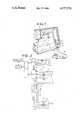
- FIG. 1is a sewing machine bearing an embodiment of the invention
- FIG. 2is a control circuit of the same.
- FIG. 1shows a sewing machine provided at a front part of a head thereof with a switch 2 for driving and stopping the sewing machine, a speed control device 3, an adjusting device 4 for adjusting stitching width, and a connecting end 6 for receiving one end of a connector 5.
- An amplitude adjusting device 7 of an external control systemis for adjusting stitching amplitude by a foot stepping operation, and has the other connecting end 9 of the connector 5. When the connecting ends 6 and 9 are connected to each other, the external control system amplitude adjusting device 7 is operated in place of the stitching width adjusting device 4.
- an electronic memorystores stitch control signals, program control signals and others, and together with a central processing unit (CPU), a random access memory (RAM) and input-output port (I/O) forms a micro-compouter.
- CPUcentral processing unit
- RAMrandom access memory
- I/Oinput-output port
- a speed control circuitis provided for controlling speed of a machine motor (not shown), and is designated of driving when the switch 2 is ON and is designated of speed by the speed control device 3, and gives control information thereof to CPU.
- a stitching width adjusting manual circuitis designated of adjusting values by means of the stitching width adjusting device 4 to adjust stitching width, and give control informations thereof to CPU.
- a variable resistor (VR1)is connected to a plus electric source (Vcc) and a ground (G) with its both ends, and gives electric potential of adjusting value to be received by a connecting piece (C1) to a control input terminal (B) of the manual circuit (MR).
- One connecting end of the connector 5has connecting pieces which are respectively connected to the electric source (Vcc), ground (G), connecting piece (C1) and control input terminal (B), and the connector makes a connection between the connecting piece (C1) and the control input terminal (B) via a connecting piece (C3) when it does not have a connection with the other connecting end 9.
- both ends of a variable resistor (VR2) and a connecting piece (C2)are connected to the other connecting end 9 of the connector 5 via lead wires 8.
- both ends of the variable resistor (VR2)are connected to the electric source (Vcc) and the ground (G).
- the control input terminal (B) and the connecting piece (C1)are separated by the connecting piece (C3) by connection of the connecting piece (C2) to the control input terminal (B).
- the connecting piece (C3)connects the connecting piece (C1) of the variable resistor (VR1) of the adjusting device 4 with the control input terminal (B) of the manual circuit (MR). Therefore, the stitching width is adjusted by moving the connecting piece (C1) by the hand manual operation.
- the connecting piece (C3)breaks the connection between the connecting piece (C1) and the control input terminal (B), and instead the connecting piece (C2) of the amplitude adjusting device 7 is connected to the terminal (B).
- the stitching widthis adjusted by moving the connecting piece (C2) by the foot stepping operation.
- the external system amplitude adjusting deviceis made detachably connected with respect to the front part of the head of the sewing machine by means of the easy structure, and the stitching width adjusting device and its function are switched each other, so that operability is excellent while the sewing machine is driven as handling the fabric such as an embroidery stitching, and there is no structural problem in the area around the head part.
Landscapes
- Engineering & Computer Science (AREA)
- Textile Engineering (AREA)
- Sewing Machines And Sewing (AREA)
Abstract
Description
This invention relates to a stitching adjustment device of a sewing machine which stores stitch control signals in an electronic memory, and produces stitched patterns.
Stitching amplitude is in general controlled by operating thumbs provided at a front part of a head of the sewing machine. When embroidery stitching or pattern stitching are performed, a large operating portion is necessary for heightening operability of the control. However, this kind of sewing machine is of multi-functions, and it is difficult to furnish operating levers for adjustment at the head of the sewing machine due to problems of a furnishing space or structural conditions of printed electronic parts and operating parts thereof. The manual operation of the lever causes inconvenience in handling the fabric during operation.
The present invention to solve such problems as mentioned above, in which an amplitude adjusting device of an external control system is prepared which has a connector via a lead wire and is operated by foot stepping, independently of a stitching width adjusting device provided at the head of the sewing machine for adjusting amplitude under stitching, and which is detachably attached to the head of the sewing machine through said connector, and works when connected to the head of the sewing machine, in place of the stitching width adjusting device provided at the head of the sewing machine.
FIG. 1 is a sewing machine bearing an embodiment of the invention, and
FIG. 2 is a control circuit of the same.
An embodiment will be explained in reference to the attached drawing. FIG. 1 shows a sewing machine provided at a front part of a head thereof with aswitch 2 for driving and stopping the sewing machine, aspeed control device 3, anadjusting device 4 for adjusting stitching width, and a connectingend 6 for receiving one end of aconnector 5.
An amplitude adjustingdevice 7 of an external control system is for adjusting stitching amplitude by a foot stepping operation, and has the other connectingend 9 of theconnector 5. When the connectingends amplitude adjusting device 7 is operated in place of the stitchingwidth adjusting device 4.
In FIG. 2, an electronic memory (ROM) stores stitch control signals, program control signals and others, and together with a central processing unit (CPU), a random access memory (RAM) and input-output port (I/O) forms a micro-compouter.
A speed control circuit (SP) is provided for controlling speed of a machine motor (not shown), and is designated of driving when theswitch 2 is ON and is designated of speed by thespeed control device 3, and gives control information thereof to CPU.
A stitching width adjusting manual circuit (MR) is designated of adjusting values by means of the stitching width adjustingdevice 4 to adjust stitching width, and give control informations thereof to CPU.
With respect to the adjustingdevice 4, a variable resistor (VR1) is connected to a plus electric source (Vcc) and a ground (G) with its both ends, and gives electric potential of adjusting value to be received by a connecting piece (C1) to a control input terminal (B) of the manual circuit (MR).
One connecting end of theconnector 5 has connecting pieces which are respectively connected to the electric source (Vcc), ground (G), connecting piece (C1) and control input terminal (B), and the connector makes a connection between the connecting piece (C1) and the control input terminal (B) via a connecting piece (C3) when it does not have a connection with the other connectingend 9.
With respect to the external control system amplitude adjustingdevice 7, both ends of a variable resistor (VR2) and a connecting piece (C2) are connected to the other connectingend 9 of theconnector 5 via lead wires 8. When the connectingend 9 is connected to the connectingend 6, both ends of the variable resistor (VR2) are connected to the electric source (Vcc) and the ground (G). The control input terminal (B) and the connecting piece (C1) are separated by the connecting piece (C3) by connection of the connecting piece (C2) to the control input terminal (B).
A next reference will be made to service of the above mentioned structure. If theconnecting ends device 4 with the control input terminal (B) of the manual circuit (MR). Therefore, the stitching width is adjusted by moving the connecting piece (C1) by the hand manual operation.
If theconnecting ends amplitude adjusting device 7 is connected to the terminal (B). Thus, the stitching width is adjusted by moving the connecting piece (C2) by the foot stepping operation.
According to the invention, the external system amplitude adjusting device is made detachably connected with respect to the front part of the head of the sewing machine by means of the easy structure, and the stitching width adjusting device and its function are switched each other, so that operability is excellent while the sewing machine is driven as handling the fabric such as an embroidery stitching, and there is no structural problem in the area around the head part.
While the invention has been illustrated and described as embodied in a stitching adjustment device of a sewing machine, it is not intended to be limited to the details shown, since various modifications and structural changes may be made without departing in any way from the spirit of the present invention.
Without further analysis, the foregoing will so fully reveal the gist of the present invention that other can, by applying current knowledge, readily adapt it for various applications without omitting features that, from the standpoint of prior art, fairly constitute essential characteristics of the generic or specific aspects of this invention.
Claims (2)
1. In a sewing machine comprising a stitch forming device; an electronic control device including a memory storing stitch control signals which may be selectively read out to control said stitch forming device to produce a selected pattern of stitches; means (3) for controlling a rotation speed of an electric motor for driving said sewing machine, said means being connected to said electronic control device and said motor by a speed control circuit; and means (4) for adjusting the amplitude of the stitches, said amplitude adjusting means being connected to said electronic control device by an amplitude adjusting circuit, the improvement comprising an external foot-operated controller for adjusting the amplitudes of the stitches, said foot-operated controller being positioned separately from said sewing machine; a first group of lead wires each having one end connected to said electronic control device through said amplitude adjusting circuit; a second group of lead wires each having one end connected to said foot-operated controller; and connector means including a first connector and a second connector, said first connector being provided on said sewing machine and holding an opposite end of each lead-wire of said first group, said second connector holding an opposite end of each lead wire of said second group, said second connector being detachably-connectable to said first connector so as to connect said foot-operated controller to said electronic control device through said amplitude adjusting circuit by said first and second groups of lead wires and disconnect said amplitude adjusting means from said electronic control device.
2. The sewing machine as defined in claim 1, wherein said controller is a foot-operated switch which includes a variable resistor which causes the stitching width to be adjusted as a resistance of said resistor is varied.
Applications Claiming Priority (2)
| Application Number | Priority Date | Filing Date | Title |
|---|---|---|---|
| JP1983136694UJPS6044769U (en) | 1983-09-05 | 1983-09-05 | Sewing machine seam adjustment device |
| JP58-136694[U] | 1983-09-05 |
Publications (1)
| Publication Number | Publication Date |
|---|---|
| US4577576Atrue US4577576A (en) | 1986-03-25 |
Family
ID=15181284
Family Applications (1)
| Application Number | Title | Priority Date | Filing Date |
|---|---|---|---|
| US06/644,126Expired - Fee RelatedUS4577576A (en) | 1983-09-05 | 1984-08-23 | Stitching adjustment device of a sewing machine |
Country Status (2)
| Country | Link |
|---|---|
| US (1) | US4577576A (en) |
| JP (1) | JPS6044769U (en) |
Cited By (4)
| Publication number | Priority date | Publication date | Assignee | Title |
|---|---|---|---|---|
| US20080223273A1 (en)* | 2007-03-13 | 2008-09-18 | Juki Corporation | Sewing machine |
| AU2015200644B2 (en)* | 2014-06-30 | 2017-02-02 | Janome Corporation | Sewing machine provided with zigzag motion mechanism |
| US10883212B2 (en)* | 2019-02-01 | 2021-01-05 | Zeng Hsing Industrial Co., Ltd. | Position indicating circuit for a foot controller of a sewing machine, and detecting system using the same |
| US12258693B2 (en)* | 2022-03-25 | 2025-03-25 | Brother Kogyo Kabushiki Kaisha | Sewing machine and embroidery device |
Citations (2)
| Publication number | Priority date | Publication date | Assignee | Title |
|---|---|---|---|---|
| US4299182A (en)* | 1978-07-28 | 1981-11-10 | Janome Sewing Machine Co., Ltd. | Two-way operation system control device for sewing machines |
| US4401042A (en)* | 1980-03-25 | 1983-08-30 | Janome Sewing Machine Co., Ltd. | Electronic control sewing machine |
- 1983
- 1983-09-05JPJP1983136694Upatent/JPS6044769U/enactivePending
- 1984
- 1984-08-23USUS06/644,126patent/US4577576A/ennot_activeExpired - Fee Related
Patent Citations (2)
| Publication number | Priority date | Publication date | Assignee | Title |
|---|---|---|---|---|
| US4299182A (en)* | 1978-07-28 | 1981-11-10 | Janome Sewing Machine Co., Ltd. | Two-way operation system control device for sewing machines |
| US4401042A (en)* | 1980-03-25 | 1983-08-30 | Janome Sewing Machine Co., Ltd. | Electronic control sewing machine |
Cited By (4)
| Publication number | Priority date | Publication date | Assignee | Title |
|---|---|---|---|---|
| US20080223273A1 (en)* | 2007-03-13 | 2008-09-18 | Juki Corporation | Sewing machine |
| AU2015200644B2 (en)* | 2014-06-30 | 2017-02-02 | Janome Corporation | Sewing machine provided with zigzag motion mechanism |
| US10883212B2 (en)* | 2019-02-01 | 2021-01-05 | Zeng Hsing Industrial Co., Ltd. | Position indicating circuit for a foot controller of a sewing machine, and detecting system using the same |
| US12258693B2 (en)* | 2022-03-25 | 2025-03-25 | Brother Kogyo Kabushiki Kaisha | Sewing machine and embroidery device |
Also Published As
| Publication number | Publication date |
|---|---|
| JPS6044769U (en) | 1985-03-29 |
Similar Documents
| Publication | Publication Date | Title |
|---|---|---|
| EP0077788B1 (en) | A driving control device | |
| US4577576A (en) | Stitching adjustment device of a sewing machine | |
| US4726307A (en) | Two-needle corner sewing machine | |
| US4280423A (en) | Display arrangement for giving a visible pattern corresponding to one or more stitch parameters in a sewing machine | |
| JPS6351717B2 (en) | ||
| US4501210A (en) | Electrode control sewing machine | |
| JP2649537B2 (en) | Embroidery machine with automatic identification device | |
| US4342271A (en) | Stitch length range indicating arrangement in a multiple pattern sewing machine | |
| JPS6029517B2 (en) | sewing machine | |
| US4098206A (en) | Electronic motor speed regulating system having adjustable high and low speed ranges | |
| US4413577A (en) | Pattern feed balancing arrangement in an electronically controlled sewing machine | |
| US4161150A (en) | Simplified actuation of two step buttonhole in electronically controlled sewing machine | |
| US4318359A (en) | Pattern generator for electronic sewing machines | |
| US5008601A (en) | Multifunction switching control system | |
| US4164192A (en) | Sewing machine motor speed limiting by pattern selection | |
| US4694762A (en) | Sewing machine control apparatus | |
| US4055130A (en) | Bight stop mechanism for sewing machines | |
| US4509445A (en) | Sewing machine control device | |
| US4149476A (en) | Twin needle memory device | |
| US4599962A (en) | Electronic sewing machine | |
| JP2686967B2 (en) | Automatic embroidery sewing machine | |
| JP2879275B2 (en) | Automatic thread trimming sewing machine for pattern sewing | |
| US4736697A (en) | Fabric presser device of a sewing machine | |
| US4142474A (en) | Sewing machine patterning means | |
| JP2879274B2 (en) | Automatic thread trimming sewing machine for pattern sewing |
Legal Events
| Date | Code | Title | Description |
|---|---|---|---|
| AS | Assignment | Owner name:JANOME SEWING MACHINE CO., LTD. NO. 1-1, KYOBASHI, Free format text:ASSIGNMENT OF ASSIGNORS INTEREST.;ASSIGNORS:HANYU, SUSUMU;KATO, KENJI;REEL/FRAME:004312/0854 Effective date:19840810 Owner name:JANOME SEWING MACHINE CO., LTD. A CORP. OF JAPAN,J Free format text:ASSIGNMENT OF ASSIGNORS INTEREST;ASSIGNORS:HANYU, SUSUMU;KATO, KENJI;REEL/FRAME:004312/0854 Effective date:19840810 | |
| FEPP | Fee payment procedure | Free format text:PAYOR NUMBER ASSIGNED (ORIGINAL EVENT CODE: ASPN); ENTITY STATUS OF PATENT OWNER: LARGE ENTITY | |
| FPAY | Fee payment | Year of fee payment:4 | |
| FPAY | Fee payment | Year of fee payment:8 | |
| REMI | Maintenance fee reminder mailed | ||
| LAPS | Lapse for failure to pay maintenance fees | ||
| FP | Lapsed due to failure to pay maintenance fee | Effective date:19980325 | |
| STCH | Information on status: patent discontinuation | Free format text:PATENT EXPIRED DUE TO NONPAYMENT OF MAINTENANCE FEES UNDER 37 CFR 1.362 |