US4577197A - Ink jet printer droplet height sensing control - Google Patents
Ink jet printer droplet height sensing controlDownload PDFInfo
- Publication number
- US4577197A US4577197AUS06/692,260US69226085AUS4577197AUS 4577197 AUS4577197 AUS 4577197AUS 69226085 AUS69226085 AUS 69226085AUS 4577197 AUS4577197 AUS 4577197A
- Authority
- US
- United States
- Prior art keywords
- droplets
- droplet
- swath
- printer
- ink jet
- Prior art date
- Legal status (The legal status is an assumption and is not a legal conclusion. Google has not performed a legal analysis and makes no representation as to the accuracy of the status listed.)
- Expired - Fee Related
Links
- 238000012360testing methodMethods0.000claimsabstractdescription31
- 238000007639printingMethods0.000claimsabstractdescription26
- 230000004044responseEffects0.000claimsabstractdescription13
- 230000003247decreasing effectEffects0.000claimsdescription4
- 238000010408sweepingMethods0.000claims2
- 239000000835fiberSubstances0.000description9
- 230000015572biosynthetic processEffects0.000description4
- 239000013307optical fiberSubstances0.000description3
- 238000001514detection methodMethods0.000description2
- 230000000694effectsEffects0.000description2
- 230000005686electrostatic fieldEffects0.000description2
- 239000012530fluidSubstances0.000description2
- 230000007246mechanismEffects0.000description2
- 238000000034methodMethods0.000description2
- 238000012986modificationMethods0.000description2
- 230000004048modificationEffects0.000description2
- 230000000737periodic effectEffects0.000description2
- 230000008569processEffects0.000description2
- 230000001960triggered effectEffects0.000description2
- 238000011109contaminationMethods0.000description1
- 238000012937correctionMethods0.000description1
- 230000007423decreaseEffects0.000description1
- 238000013461designMethods0.000description1
- 230000005684electric fieldEffects0.000description1
- 230000004886head movementEffects0.000description1
- 230000003116impacting effectEffects0.000description1
- 238000007641inkjet printingMethods0.000description1
- 238000009434installationMethods0.000description1
- 238000005259measurementMethods0.000description1
- NJPPVKZQTLUDBO-UHFFFAOYSA-NnovaluronChemical compoundC1=C(Cl)C(OC(F)(F)C(OC(F)(F)F)F)=CC=C1NC(=O)NC(=O)C1=C(F)C=CC=C1FNJPPVKZQTLUDBO-UHFFFAOYSA-N0.000description1
- JTJMJGYZQZDUJJ-UHFFFAOYSA-NphencyclidineChemical compoundC1CCCCN1C1(C=2C=CC=CC=2)CCCCC1JTJMJGYZQZDUJJ-UHFFFAOYSA-N0.000description1
- 230000005855radiationEffects0.000description1
- 238000004064recyclingMethods0.000description1
- 230000000638stimulationEffects0.000description1
- 239000002699waste materialSubstances0.000description1
- XLYOFNOQVPJJNP-UHFFFAOYSA-NwaterSubstancesOXLYOFNOQVPJJNP-UHFFFAOYSA-N0.000description1
Images


Classifications
- B—PERFORMING OPERATIONS; TRANSPORTING
- B41—PRINTING; LINING MACHINES; TYPEWRITERS; STAMPS
- B41J—TYPEWRITERS; SELECTIVE PRINTING MECHANISMS, i.e. MECHANISMS PRINTING OTHERWISE THAN FROM A FORME; CORRECTION OF TYPOGRAPHICAL ERRORS
- B41J2/00—Typewriters or selective printing mechanisms characterised by the printing or marking process for which they are designed
- B41J2/005—Typewriters or selective printing mechanisms characterised by the printing or marking process for which they are designed characterised by bringing liquid or particles selectively into contact with a printing material
- B41J2/01—Ink jet
- B41J2/07—Ink jet characterised by jet control
- B41J2/125—Sensors, e.g. deflection sensors
Definitions
- the present inventionrelates to ink jet printing and, more particularly, to an ink jet printer having a single reciprocating jet which concurrently sweeps droplets in a direction perpendicular to the jet reciprocating direction while the jet reciprocates to print full pages of information one swath at a time.
- the ink jet printerhas a height control sensor for maintaining predetermined spacing between swaths of printed information.
- U.S. Pat. Nos. 3,465,350 and 3,465,351 to R. I. Keur et al. and U.S. Pat. No. 3,555,558 to Shermandisclose ink droplet printing devices in which an ink nozzle is moved perpnedicularly to the movement of web. Ink droplet placement is controlled by an electric field and unnecessary drops are deflected to a waste reservoir. Circuitry is provided to ensure that the droplets are charged in phase with data or video signals and that carriage motion variables are connected to ensure a uniform margin.
- U.S. Pat. No. 3,737,914 to Hertzdiscloses a multi-jet printer whose printing head is moved from side-to-side, while the recording mechanism is moved in a direction perpendicular to that of the head movement.
- U.S. Pat. No. 4,050,075 to Hertz et al.discloses an ink jet writing system mounted on a travelling carriage, the carriage and recording medium being selectively moved to effect relative movement between them.
- U.S. Pat. No. 4,178,595 to Jinnai et al. and U.S. Pat. No. 4,313,684 to Tazaki et al.disclose ink jet printers with oscillating print heads but are of the type which use drops-on-demand rather than print heads which emit continuous streams of ink that are concurrently broken into droplets and charged for deflection by an electrostatic field to the proper location on a receiving surface or to a gutter for recirculation.
- U.S. Pat. No. 4,293,863 to Davis et al.discloses a printing device having an oscillating print head with a plurality of ink emitting nozzles and a recording medium that is mounted on a rotatable drum.
- the printing headis moved in either direction at a uniform velocity parallel to the area of rotation of the drum, thus printing along helical print lines or the print head may be moved a discrete distance after each rotation of the drum such that the print lines are circumferential.
- Several revolutions of the drumare necessary to print a line of complete fonts.
- U.S. Pat. No. 3,769,630 to J. D. Hill et al.discloses an ink jet system wherein the droplets not required for printing are directed to a first gutter where the charges on the collected droplets develop a current that is sensed in an electronic feedback loop for sysnchronization of the droplet formation with droplet charging.
- An auxilliary gutteris positioned to receive droplets during a checking interval when a relatively high charge is applied to the unused droplets.
- U.S. Pat. No. 4,255,754 to P. A. Crean et al.discloses the use of paired photodetectors to sense ink drops, one each for two output fibers, that are used to generate an electrical zero crossing signal.
- the zero crossing signalis used to indicate alignment or misalignment of a drop relative to the bisector of the distance between two output fibers.
- the sensor of this patentemploys one input optical fiber and at least two output optical fibers. The free ends of the fibers are spaced a small distance from each other; the free end of the input fiber is on one side of the flight path of the drops and the free ends of the output fibers are on the opposite side.
- the remote end of the input fiberis coupled to a light source, such as an infrared light emitting diode (LED).
- the remote ends of each output fiberare coupled to separate photodetectors such as, for example, a photodiode responsive to infrared radiation.
- the inkis substantially a dye dissolved in water and is, of course, transparent to the infrared, thus reducing the problems of contamination usually associated with ink drop sensors.
- the photodiodesare coupled to differential amplifiers, so that the output of the amplifiers are measurements of the location of drops relative to the bisector of the distance between the output fiber ends confronting their associated input fibers and drops passing therebetween. Amplifier outputs are used in servo loops to position subsequently generated drops to the bisector location. The zero crossing may be used, depending upon its orientation with respect to the drop stream direction, as a time reference to measure the velocity of the drop. Therefore, the drop velocity information may be used in a servo loop to achieve a desired velocity.
- the sensor of this inventionuses a sensor similar to the one in U.S. Pat. No. 4,255,754, though the use and purpose is different, and the disclosure of this patent is incorporated by reference herein.
- U.S. Pat. No. 3,886,564 to H. E. Naylor et al.discloses the use of differentially sensed, capacitive sensors to determine when a drop passing therebetween is equally distant therefrom, and such a sensor may be used to determine height and placement of drops in an ink stream.
- U.S. Pat. No. 3,992,713 to J. M. Carmichael et al.discloses a sensor for synchronizing the drop break-off time to the charge applied by the charge electrode by using a pedestal voltage level rather than by referencing the charge level to zero, thus enabling the charge pulses to reach the required levels more quickly and accurately.
- This synchronizing sensoris located to one side of the carriage printer.
- U.S. Pat. No. 4,063,253 to S. Ito et al.discloses a sensor and circuitry to detect ink drops for a predetermined time period and indicating improper operation if this should occur.
- the disorder sensed in the recording operationmay be indicated by energizing a light or stopping the recording.
- U.S. Pat. No. 4,136,345 to M. H. Neville et aldiscloses the placement of several spaced apart serially arranged sensors which are positioned in a sensing plane parallel to the deflection plane of the ink drops. One of the sensors is positioned for sensing ink drops after deflection. Timing means are connected to the sensors to compare the time of occurrence of a drop sensed between two sensors and a third one to indicate whether the drop being sensed is high or low relative to a predetermined optimum height of the drop.
- U.S. Pat. No. 4,328,504 to H. Weber et al.discloses a sensor and circuitry for sensing ink drops after impacting the recording medium and comparing the sensor signals to desired signals for correcting the printing.
- U.S. Pat. No. 4,333,083 to S. F. Aldridgediscloses a plurality of spaced conductive members on opposite sides of an ink jet stream and having an amplifier circuit connected thereto to develop an output signal in response to the passage of charged drops. The output signal is processed to measure flight time.
- None of the above referencesoptically sense one or more of the upper and lower droplets in one vertical column sweep of droplets that normally print horizontal swaths of information one swath at a time from a single reciprocating jet and, in response thereto, determine and compare the interdroplet spacing of the ink droplets to a desired spacing. Any difference between the determined spacing and the desired spacing is indicative of correction required. At least one of the printer operating parameters is adjusted to maintain the correct interdroplet spacing for proper stitching between the printed and subsequently printed swaths based on the comparison.
- a height control sensoris positioned adjacent one end of a platen holding a recording medium, such as paper, to sense a sweep of droplets before or after a swath of information is printed on the paper.
- a mounting structure fixedly attached to the stationary base of the ink jet printerhas an elongated opening therein for the passage of a sweep of test droplets.
- a gutter to receive the sweep of test dropletsis fixedly mounted to the printer base behind the mounting structure opening.
- First and second pairs of photodetectorsare mounted at predetermined locations on the mounting structure adjacent one elongated edge of the opening therein.
- the charging status of each droplet in the sweep of test dropletsare sequentially stored in a memory unit of the ink jet printer controller.
- the quantity of droplets therebetween and consequently the interdroplet spacingmay be determined and adjusted.
- separate sequential bursts of dropletsare directed to vertically fanned, overlapping pixel targets in a gutter and past the upper and lower photodetector pairs of the height control sensor. This causes an increase number of droplets to past each photodetector pair with the result that several droplets are detected by each photodetector pairs.
- the photodetector pairsthrough differential sensing, produce signals from which the droplet having a trajectory closest to the desired one is determined and identified from a history or log table stored in the memory of the printer's controller.
- the printheadAt the end of each printed swath, at predetermined times, or after predetermined numbers of printed swaths, the printhead is moved beyond its normal reciprocating print width to a location in alignment with the height control sensor and associated gutter for a check on the interdroplet spacing of the vertically swept droplets.
- This check or calibrationis required since the droplet trajectories tend to drift during operation, for example, due to pressure fluctuations in the droplet generator of the printhead.
- the controllerreceives signals from the control sensor via associated circuitry from which the controller uses to adjust one of the operating parameters of the printer to place the droplets in their correct trajectories and thus maintain the proper interdroplet spacings.
- the parameter adjustedis the droplet generator pressure which gradually decreases because of minute system pressure losses through seals and the like.
- the present inventionovercomes the complex sensing devices and circuitries and, in many cases, varying degrees of inaccuracy caused by weak field intensities sensed by capacitive sensors of the prior art ink jet printers by providing highly accurate, differential sensing photodetector pairs which identify the trajectories of droplets in a columnar sweep of test droplets passing thereby and locates them in a sequentially established history or log table whereby the total number of droplets determined is directly related to the interdroplet spacing which may be corrected by adjusting the operating parameters of the ink jet printer, thus correcting for the normal drift of the droplet trajectories.
- FIG. 1is a side elevation view in schematic form of a single, continuous stream type ink jet printer having a reciprocating droplet generator and a height control sensor according to the present invention.
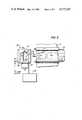
- FIG. 2is a front view of the portion of the ink jet printer as viewed along section 2--2 of FIG. 1.
- FIG. 3is an enlarged, partial perspective view of the ink jet printer of FIG. 1 showing the height control sensor.
- the pictorial ink jet printer of FIG. 1includes a reciprocating printhead 1 shown in dashed lines which comprises a droplet generator 14 with a grounded ink manifold 7 having a single nozzle 2 through which fluid ink 11 is emitted under pressure creating a continuous stream 3 of the ink from the nozzle.
- a piezoelectric device 4 coupled to a wall of the manifold 7periodically stimulates the ink with a pressure wave which promotes the formation of droplets 5 adjacent a charging electrode 6.
- the inkis conductive, so that voltage applied to the charging electrode at the moment of drop formation, results in a droplet 5 having a charge proportional to the applied voltage.
- the charged dropletsare deflected by deflection plates 10 and 12 in the plane of FIG. 1 or in the direction of periodic stepped movement of the recording medium 19 as depicted by arrow 20.
- the deflection plates 10, 12have a high electrostatic field between them established by + and - voltage potentials.
- the charging voltages applied to charging electrode 6are in the range of 10 to 200 volts, while the potential difference between the deflection plates 10, 12 is in the vicinity of 2000-3000 volts.
- the droplets not directed to the recording mediumare directed to gutter 9 in deflection plate 10.
- the gutter directed dropletsmay be charged or uncharged, as a design choice, but in the preferred embodiment of FIG. 1, the uncharged droplets follow the straight line trajectory 8 to the recording medium.
- a height control sensor 16is located adjacent one end of an elongated platen 23 as more fully described later with respect to FIGS. 2 and 3.
- the height control sensoroperates in a servo loop with the droplet generator controls to adjust the spacing of droplets 5 which are swept or fanned in a vertical direction or columnar manner.
- the droplet vertical deflection processis substantially linear and the droplets are substantially evenly spaced, so that the droplets can be positioned accurately within its vertical range to all droplet target areas on the recording medium, hereinafter referred to as pixels 13. See FIG. 2.
- the vertical height of the droplet deflectionis that number of pixels required to print a selected character or font.
- the charged droplets 5 from nozzle 2form a vertical trace height or deflection bandwidth "H" at the printing plane of the recording medium.
- this heightis composed of a column of twelve droplets or pixels.
- the printhead 1has a droplet generator 14 with a single nozzle 2 and is mounted on a movable carriage 40 and adapted for reciprocal movement by means well known in the art such as slide rails 41. Reciprocating traversal of the platen 23 by the printhead is accomplished by drive means 25 in response to signals from the controller 27 through digital to analog (D/A) converter 26 and amplifier 21.
- D/Adigital to analog
- FIG. 1The reciprocating droplet generator's nozzle is aimed towards the recording medium.
- the direction of reciprocationis depicted by arrow 17 (FIG. 3), which direction is parallel to the platen and the portion of the recording medium thereon which is to receive the ink droplets.
- the drop generatoris generally positioned on one end of the platen when not printing, and traverses back and forth adjacent the recording medium on the platen, printing in both directions during the printing mode. At the end of some or each traversal, the droplet generator proceeds a relatively short distance beyond the end of the platen to the height sensor 16 where one or more columnar sweeps of test drops are sensed.
- the single stream of dropletsare continually swept in a direction perpendicular to the traversal direction for a height "H," so that a stripe or swath of information having height "H" may be printed, one swath at a time, until a full page of information is recorded.
- the platenis stepped in a direction perpendicular to the droplet generator reciprocating direction for a distance of one swath height of "H" distance.
- the droplet generator, charging electrode and deflection platesare all mounted on the carriage 40 to form the printhead of the ink jet printer.
- a portion of the printheadis omitted and the charging electrode is partially omitted for clarity of operation of the height control sensor 16.
- the ink jet printeris designed to record information on an incrementally movable recording medium, which is held stationary during the printing of a swath of information then stepped the distance of one swath prior to the printing of the next swath of information.
- the system of FIG. 1makes black marks on the recording medium, for example, white paper, in response to electrical information signals.
- the information or video signalsare applied to the controller 27 which is a microprocessor such as, for example, the model 6800 sold by the Motorola Corporation.
- Video signals representative of an imageare stored, for example, in designated memory locations within the controller.
- the controlleralso includes output ports that issue electrical control signals to the various system components.
- Amplifier 29couples the controller to the recording medium stepper motor 22. Under the direction of the controller, the recording medium is stepped an incremental distance "H" at the end of each traversal by the printing head or droplet generator.
- the ink dropletsare directed to the recording medium or to the gutter 9, depending whether, during the traversal of the droplet generator, the droplets are required for printing at specific pixel locations or not.
- the controller 27also includes an output to drive the piezoelectric device 4 that promotes the droplet formation.
- the piezoelectric deviceis driven at a frequency that gives rise to droplet generation rates typically in the vicinity of 100 to 150 kilohertz (KHz).
- the amplifier 37 and D/A converter 38couple the piezoelectric device and the controller together.
- a flexible conduit 42connects the gutter 9 to the ink reservoir 39 to permit the unused ink to be recycled.
- Another conduit 28connects the gutter 24, used for the collection of the sweep of test ink droplets or a known proportion thereof, to the ink reservoir for recycling the ink received by this gutter.
- the trajectories to the upper and lowermost pixels in the columnar sweep of pixelsis diagrammatically depicted by dashed lines to show the vertical deflection of the droplets as they are directed to the recording medium in FIG. 1 and to the gutter 24 in FIG. 3, when the printhead is in the test position.
- the droplets not targeted for the recording medium during the printing of the swath of informationare, of course, directed to gutter 9.
- the controller 27in response to receipt of digitized data signals at its input terminal 43, applies the charging voltage to the charging electrode 6 via D/A converter 35 and amplifier 36 by means well known in the art to convert video or digitized data signals to droplet charge signals and to compensate concurrently the charge signals for aerodynamic and electrostatic effects.
- D/A converter 35 and amplifier 36by means well known in the art to convert video or digitized data signals to droplet charge signals and to compensate concurrently the charge signals for aerodynamic and electrostatic effects.
- the height control sensor 16is optionally placed at one end or the other of the platen 23 and positioned to receive a columnar sweep of test droplets or predetermined portion thereof from the printhead.
- the height control sensoris aligned with the swath 44, shown in dashed line, having printed information or to have information printed therein, so that the only movement necessary by the printhead to position itself for emitting the sweep of test droplets or a portion of the sweep of droplets is a periodic extension of its normal printing movement (see arrow 17 in FIG. 3) a short distant to align the nozzle with the height control sensor target or opening 45.
- a pair of droplet sensors 46are placed in the printing plane of that portion of the recording medium 19 targeted to receive a single swath of printing.
- the pair of sensors 46are mounted on a mounting structure 47 which is fixedly attached to the stationary printer base (not shown).
- the mounting structurehas an elongated opening 45 oriented to have a vertical or columnar sweep of test droplets pass therethrough.
- a gutter 24is fixedly positioned downstream from height control sensor to receive the sensed test droplets for collection and return to the ink reservoir 39 by conduit 28.
- Each pair of sensors 46have a pair of photodetectors 48 fixedly mounted at predetermined positions adjacent a one of the elongated edges 49 to sense and determine the uppermost droplet and the lowermost droplet used in the columnar sweep of test sweep of droplets or predetermined portion thereof that pass through the opening 45.
- Optical fibers 50are mounted on the mounting structure with their ends 51 adjacent the elongated opening edge opposite the one having the droplet sensors 46 and confronting the pairs of photodetectors.
- the charging electrode 6is partially removed and the deflection plates 10, 12 are omitted for clarity to better show the trajectories of the uppermost and lowermost droplets 5 that are shown in dashed line through the height control sensor 16 and into gutter 24.
- the difference in the upper and lower droplets as they pass the pairs of photodetectors 48is the height of the swath 44 of information printed or to be printed and is indicated as "H.”
- a sequence or sweep of test dropletsmay be thrown past the height control sensor 16 and the location of the droplets that pass at the centerline between each pair of photodetectors 48 are identified by circuitry 30 and recorded in a memory unit of the controller 27 as the upper and lower droplets in the printing bandwidth "H.”
- a test sweep of droplets for the entire swath heightis not required. Instead, separate sequential bursts or sweeps of droplets are directed to the vicinity of the upper and lower pixel of the swath height "H.” Each burst of test droplets are directed to columns of overlapping pixel targets in the plane of the swath printed or to be printed on the recording medium. The burst of sequentially generated test droplets may be directed past either the upper or the lower drop sensor 46 first, then directed past the other one.
- Each burst of dropletsmust have in trajectories which encompass or include in its range of trajectories, the desired droplet trajectory which would direct a droplet to first the upper pixel in the swath then the lower pixel or visa versa.
- the closest droplet trajectory to the desired trajectoryis identified and, via the sensor circuitry 30 and controller 27, the voltage of the droplet following that trajectory is identified.
- the controllerautomatically adjusts the printer operating parameters to maintain the desired upper and lower droplet trajectories of the printing sweep of droplets. Although many parameters of the printer may drift out of tolerance, they may be compensated for by varying the drop generator pressure, so that it is primarily the drop generator pressure that is adjusted in response to the signals generated by the sensor circuitry.
- the sequence and voltage at time of droplet chargingare some of the droplet characteristics of each test droplet that are temporarily stored in a history or log table in the memory unit of the controller.
- the upper and lower test droplets and their interspatial distancescan be readily determined by the controller by means well known in the art.
- the number of test droplets found by the controller to pass the height control sensor 16is compared to the predetermined desired number of droplets and the information used to maintain or obtain the desired number of droplets per swath height "H.”
- the number of droplets per swath height "H"is determined by one of several printhead parameters such as the droplet generator manifold pressure, ink stream stimulation frequency and the like.
- the controllermaintains the correct interdroplet spacing per swath height by adjusting at least one of the ink jet printer parameters such as the charging voltage, deflection voltage, manifold pressure, etc.
- the controllermaintains the correct interdroplet spacing per swath height "H" by increasing or decreasing the fluid pressure in the droplet generator manifold 7 by a servo controller pump 32.
- the signal from the controller 27 to the pumpis via D/A converter 33 and amplifier 34.
- test sweep of dropletsmight be a simple sequential fan of droplets or two separate bursts of vertically fanned droplets that are directed past each droplet sensor 46 as described above, a more complex pattern could be used.
- the sweep of test dropletscould be vertically fanned in such a manner to enable the pair of sensors 46 and sensor circuitry 30 to account for possible mechanical misalignment encountered in mounting the photodetectors 48 on the mounting structure 47 or the mounting of the mounting structure 47 on the printer base.
- the detection algorithm of the sensor circuitry 30will not be affected by any overall motion of the height control sensor.
- the sensors 46are provided with electronic circuitry 30 which determines whether any droplet passing the height control sensor 16 falls into one of three disjunct classes: not sensed, sensed high, or sensed low as well as identifying the ones passing the centerline between the pairs of photodetectors 48.
- the sensed high and sensed lowrefer to the high and low sides of each sensor 46.
- the controller 27utilizes this information to build the history table showing the status of each droplet thrown.
- the desired control of the number of droplets per swath heightis provided by a straight forward algorithm for use by the controller in analyzing the history table generated and enabling the adjustment of the droplet generator manifold pressure accordingly.
- a variety of compensation algorithmswhich are familiar to those skilled in the art can be prepared and used to adjust the manifold pressure to account for system pressure losses as well as to print swaths with higher or lower heights.
- the circuitry 30amplifies signals from the sensor and directs the amplified signals into a comparator included therein which is triggered one way if the sensed-high signal is larger than the sensed-low signal and is triggered the other way, if the sensed-low signal is larger.
- This informationis encoded along with a droplet detect signal generated when a droplet passes the bisector location between a pair of photodectors 48 and the two signals are read by the controller 27. The presence of the two signals are used by the controller to decide if a droplet 5 was detected and, if so, on which side of the pair of photodetectors (or whether it was exactly in the center between them) it was on.
- the controller 27may make an individual decision on each subsequent droplet produced by the droplet generator. Although these parameters may be adjusted, the preferred embodiment utilizes the height control sensor to adjust the pressure in the ink manifold 7 to maintain the appropriate upper and lower droplet trajectories to cause the droplets to impact the appropriate upper and lower pixels on each swath height. Thus, the desired number of droplets or interdroplet spacing for the swath height to be printed by the reciprocating, single nozzle printhead is maintained by adjusting the droplet generator manifold pressure.
- the controller 27can utilize the fact that there is a known time window during which the first droplet in a test sweep should be detected, the height control sensor 16 may be disabled until this window starts, thus reducing the probability of misleading signals from the everpresent electronic noise.
- the height control sensor of this inventionis the high degree of accuracy achieved by the two pairs of photodetectors 48, since this configuration is not affected by mechanical shifts in the sensor or by changes of the gain or offset of the electric circuitry.
- a flaw in many prior art systemsis that they use only a single sensor.
- the use of a pair of sensorsi.e., two sensors having a pair of photodetectors each) makes the installation replacement or adjustment of the height control sensor a relatively simple process with large tolerances.
- the present inventionutilizes a height control sensor having two pair of photodetectors to sense a columnar sequence or sweep of droplets or predetermined portions thereof from a reciprocating printhead emitting a single stream of ink droplets in order to identify the droplets having trajectories closest to the desired trajectories that direct them to the upper and lowermost pixels in a printed swath.
- a controllerdetermines the total number of droplets in the sweep between the identified upper and lower droplets from a history table generated in a memory unit therein and compares the actual number of droplets in the column of droplets between each pair of photodetectors against a desired number of droplets.
- a signalis generated by the ink jet printer controller in response to the comparison of the sweep of test droplets to the desired number of droplets to adjust a parameter of the ink jet printer, such as its stream pressure to increase droplet velocity as necessary to maintain the appropriate number of ink droplets per swath of information to be printed and to ensure that the individual swaths remain of constant height.
- a parameter of the ink jet printersuch as its stream pressure to increase droplet velocity as necessary to maintain the appropriate number of ink droplets per swath of information to be printed and to ensure that the individual swaths remain of constant height.
- separate bursts of sequentially generated test dropletsare fanned by each of the upper and lower droplet sensors.
- the test dropletsmay be directed to overlapping pixel targets.
- the droplet parameters of the closest droplet sensed by the upper and lower droplet sensorsis used to adjust the droplet trajectories aimed for the upper and lower pixels in a swath of information to be printed and is used to establish vertical interdroplet spacings in the swath.
- a constant print heightprovides a high quality image without gaps or overlaps between the individual adjacent swaths of printed information which collectively make up a full page of information.
Landscapes
- Particle Formation And Scattering Control In Inkjet Printers (AREA)
Abstract
Description
Claims (8)
Priority Applications (2)
| Application Number | Priority Date | Filing Date | Title |
|---|---|---|---|
| US06/692,260US4577197A (en) | 1985-01-17 | 1985-01-17 | Ink jet printer droplet height sensing control |
| JP61006172AJPH0729439B2 (en) | 1985-01-17 | 1986-01-14 | Ink jet printer |
Applications Claiming Priority (1)
| Application Number | Priority Date | Filing Date | Title |
|---|---|---|---|
| US06/692,260US4577197A (en) | 1985-01-17 | 1985-01-17 | Ink jet printer droplet height sensing control |
Publications (1)
| Publication Number | Publication Date |
|---|---|
| US4577197Atrue US4577197A (en) | 1986-03-18 |
Family
ID=24779874
Family Applications (1)
| Application Number | Title | Priority Date | Filing Date |
|---|---|---|---|
| US06/692,260Expired - Fee RelatedUS4577197A (en) | 1985-01-17 | 1985-01-17 | Ink jet printer droplet height sensing control |
Country Status (2)
| Country | Link |
|---|---|
| US (1) | US4577197A (en) |
| JP (1) | JPH0729439B2 (en) |
Cited By (35)
| Publication number | Priority date | Publication date | Assignee | Title |
|---|---|---|---|---|
| WO1989000108A1 (en)* | 1987-07-08 | 1989-01-12 | Hertz Carl H | Electronic method and device for adjustment of jet direction in an ink jet apparatus |
| US5069556A (en)* | 1989-03-17 | 1991-12-03 | Hitachi, Ltd. | Method for correcting drift of printing position and printing apparatus for practising the same |
| US5352887A (en)* | 1992-08-28 | 1994-10-04 | Motorola, Inc. | Circuit for detecting a droplet in motion and method therefor |
| US5956055A (en)* | 1997-10-10 | 1999-09-21 | Lexmark International, Inc. | Method of compensating for skewed printing in an ink jet printer |
| US6062682A (en)* | 1996-09-16 | 2000-05-16 | Samsung Electronics Co., Ltd. | Method for homogenizing a pigment ink contained in an ink cartridge mounted in an ink jet printer |
| US6347857B1 (en) | 1999-09-23 | 2002-02-19 | Encad, Inc. | Ink droplet analysis apparatus |
| WO2002040273A3 (en)* | 2000-11-09 | 2002-09-12 | Therics Inc | Method and apparatus for obtaining information about a dispensed fluid during printing |
| US6616261B2 (en) | 2001-07-18 | 2003-09-09 | Lexmark International, Inc. | Automatic bi-directional alignment method and sensor for an ink jet printer |
| US6629747B1 (en) | 2002-06-20 | 2003-10-07 | Lexmark International, Inc. | Method for determining ink drop velocity of carrier-mounted printhead |
| US20030189611A1 (en)* | 2002-04-08 | 2003-10-09 | Fan Tai-Lin | Jet printer calibration |
| US20050185015A1 (en)* | 2004-02-16 | 2005-08-25 | Yuji Yakura | Liquid discharger and method for controlling the same |
| US20060139392A1 (en)* | 2004-12-28 | 2006-06-29 | Cesar Fernandez | Detection apparatus |
| US20120013735A1 (en)* | 2010-07-15 | 2012-01-19 | Kai Tao | IV monitoring by video and image processing |
| US9372486B2 (en) | 2011-12-21 | 2016-06-21 | Deka Products Limited Partnership | System, method, and apparatus for monitoring, regulating, or controlling fluid flow |
| US9435455B2 (en) | 2011-12-21 | 2016-09-06 | Deka Products Limited Partnership | System, method, and apparatus for monitoring, regulating, or controlling fluid flow |
| US9724466B2 (en) | 2011-12-21 | 2017-08-08 | Deka Products Limited Partnership | Flow meter |
| US9746093B2 (en) | 2011-12-21 | 2017-08-29 | Deka Products Limited Partnership | Flow meter and related system and apparatus |
| US9746094B2 (en) | 2011-12-21 | 2017-08-29 | Deka Products Limited Partnership | Flow meter having a background pattern with first and second portions |
| US9759343B2 (en) | 2012-12-21 | 2017-09-12 | Deka Products Limited Partnership | Flow meter using a dynamic background image |
| USD799025S1 (en) | 2013-11-06 | 2017-10-03 | Deka Products Limited Partnership | Apparatus to control fluid flow through a tube |
| USD802118S1 (en) | 2013-11-06 | 2017-11-07 | Deka Products Limited Partnership | Apparatus to control fluid flow through a tube |
| USD813376S1 (en) | 2013-11-06 | 2018-03-20 | Deka Products Limited Partnership | Apparatus to control fluid flow through a tube |
| USD815730S1 (en) | 2013-11-06 | 2018-04-17 | Deka Products Limited Partnership | Apparatus to control fluid flow through a tube |
| USD816829S1 (en) | 2013-11-06 | 2018-05-01 | Deka Products Limited Partnership | Apparatus to control fluid flow through a tube |
| DE102017103876A1 (en) | 2017-02-24 | 2018-08-30 | Vermes Microdispensing GmbH | Guidance system for detection devices |
| US10088346B2 (en) | 2011-12-21 | 2018-10-02 | Deka Products Limited Partnership | System, method, and apparatus for monitoring, regulating, or controlling fluid flow |
| US10228683B2 (en) | 2011-12-21 | 2019-03-12 | Deka Products Limited Partnership | System, method, and apparatus for monitoring, regulating, or controlling fluid flow |
| USD854145S1 (en) | 2016-05-25 | 2019-07-16 | Deka Products Limited Partnership | Apparatus to control fluid flow through a tube |
| US10488848B2 (en) | 2011-12-21 | 2019-11-26 | Deka Products Limited Partnership | System, method, and apparatus for monitoring, regulating, or controlling fluid flow |
| US10753850B2 (en) | 2015-10-09 | 2020-08-25 | Vermes Microdispensing GmbH | Drop-detection device |
| US10809116B2 (en) | 2015-10-09 | 2020-10-20 | Vermes Microdispensing GmbH | Light-guiding element arrangement for optical drop detection |
| USD905848S1 (en) | 2016-01-28 | 2020-12-22 | Deka Products Limited Partnership | Apparatus to control fluid flow through a tube |
| USD964563S1 (en) | 2019-07-26 | 2022-09-20 | Deka Products Limited Partnership | Medical flow clamp |
| US11744935B2 (en) | 2016-01-28 | 2023-09-05 | Deka Products Limited Partnership | Apparatus for monitoring, regulating, or controlling fluid flow |
| US11839741B2 (en) | 2019-07-26 | 2023-12-12 | Deka Products Limited Partneship | Apparatus for monitoring, regulating, or controlling fluid flow |
Citations (18)
| Publication number | Priority date | Publication date | Assignee | Title |
|---|---|---|---|---|
| US3465350A (en)* | 1968-03-13 | 1969-09-02 | Dick Co Ab | Ink drop writing apparatus |
| US3465351A (en)* | 1968-03-13 | 1969-09-02 | Dick Co Ab | Ink drop writing apparatus |
| US3555558A (en)* | 1969-01-21 | 1971-01-12 | Dick Co Ab | Ink drop writing apparatus with data synchronizing means |
| US3737914A (en)* | 1970-04-02 | 1973-06-05 | C Hertz | Liquid jet recorder |
| US3769630A (en)* | 1972-06-27 | 1973-10-30 | Ibm | Ink jet synchronization and failure detection system |
| US3828354A (en)* | 1973-09-27 | 1974-08-06 | Ibm | Ink drop charge compensation method and apparatus for ink drop printer |
| US3886564A (en)* | 1973-08-17 | 1975-05-27 | Ibm | Deflection sensors for ink jet printers |
| US3992713A (en)* | 1975-06-20 | 1976-11-16 | International Business Machines Corporation | Ink jet printing system with pedestal synchronization |
| US4050075A (en)* | 1974-10-17 | 1977-09-20 | Hertz Carl H | Ink jet method and apparatus |
| US4063253A (en)* | 1975-03-10 | 1977-12-13 | Hitachi, Ltd. | Ink jet recording apparatus |
| US4136345A (en)* | 1977-10-31 | 1979-01-23 | International Business Machines Corporation | Object deflection sensor |
| US4178595A (en)* | 1977-11-04 | 1979-12-11 | Ricoh Company, Ltd. | Ink jet printing apparatus with ink replenishing |
| US4249076A (en)* | 1977-11-23 | 1981-02-03 | Asea Aktiebolag | Optical measuring device using optical fibers |
| US4255754A (en)* | 1979-03-19 | 1981-03-10 | Xerox Corporation | Differential fiber optic sensing method and apparatus for ink jet recorders |
| US4293863A (en)* | 1979-09-12 | 1981-10-06 | The Mead Corporation | Ink jet printer with laterally movable print head |
| US4313684A (en)* | 1979-04-02 | 1982-02-02 | Canon Kabushiki Kaisha | Recording apparatus |
| US4328504A (en)* | 1980-10-16 | 1982-05-04 | Ncr Corporation | Optical sensing of ink jet printing |
| US4333083A (en)* | 1980-12-23 | 1982-06-01 | International Business Machines Corporation | Electrostatic drop sensor with sensor diagnostics for ink jet printers |
- 1985
- 1985-01-17USUS06/692,260patent/US4577197A/ennot_activeExpired - Fee Related
- 1986
- 1986-01-14JPJP61006172Apatent/JPH0729439B2/ennot_activeExpired - Lifetime
Patent Citations (18)
| Publication number | Priority date | Publication date | Assignee | Title |
|---|---|---|---|---|
| US3465350A (en)* | 1968-03-13 | 1969-09-02 | Dick Co Ab | Ink drop writing apparatus |
| US3465351A (en)* | 1968-03-13 | 1969-09-02 | Dick Co Ab | Ink drop writing apparatus |
| US3555558A (en)* | 1969-01-21 | 1971-01-12 | Dick Co Ab | Ink drop writing apparatus with data synchronizing means |
| US3737914A (en)* | 1970-04-02 | 1973-06-05 | C Hertz | Liquid jet recorder |
| US3769630A (en)* | 1972-06-27 | 1973-10-30 | Ibm | Ink jet synchronization and failure detection system |
| US3886564A (en)* | 1973-08-17 | 1975-05-27 | Ibm | Deflection sensors for ink jet printers |
| US3828354A (en)* | 1973-09-27 | 1974-08-06 | Ibm | Ink drop charge compensation method and apparatus for ink drop printer |
| US4050075A (en)* | 1974-10-17 | 1977-09-20 | Hertz Carl H | Ink jet method and apparatus |
| US4063253A (en)* | 1975-03-10 | 1977-12-13 | Hitachi, Ltd. | Ink jet recording apparatus |
| US3992713A (en)* | 1975-06-20 | 1976-11-16 | International Business Machines Corporation | Ink jet printing system with pedestal synchronization |
| US4136345A (en)* | 1977-10-31 | 1979-01-23 | International Business Machines Corporation | Object deflection sensor |
| US4178595A (en)* | 1977-11-04 | 1979-12-11 | Ricoh Company, Ltd. | Ink jet printing apparatus with ink replenishing |
| US4249076A (en)* | 1977-11-23 | 1981-02-03 | Asea Aktiebolag | Optical measuring device using optical fibers |
| US4255754A (en)* | 1979-03-19 | 1981-03-10 | Xerox Corporation | Differential fiber optic sensing method and apparatus for ink jet recorders |
| US4313684A (en)* | 1979-04-02 | 1982-02-02 | Canon Kabushiki Kaisha | Recording apparatus |
| US4293863A (en)* | 1979-09-12 | 1981-10-06 | The Mead Corporation | Ink jet printer with laterally movable print head |
| US4328504A (en)* | 1980-10-16 | 1982-05-04 | Ncr Corporation | Optical sensing of ink jet printing |
| US4333083A (en)* | 1980-12-23 | 1982-06-01 | International Business Machines Corporation | Electrostatic drop sensor with sensor diagnostics for ink jet printers |
Cited By (60)
| Publication number | Priority date | Publication date | Assignee | Title |
|---|---|---|---|---|
| WO1989000108A1 (en)* | 1987-07-08 | 1989-01-12 | Hertz Carl H | Electronic method and device for adjustment of jet direction in an ink jet apparatus |
| US5069556A (en)* | 1989-03-17 | 1991-12-03 | Hitachi, Ltd. | Method for correcting drift of printing position and printing apparatus for practising the same |
| US5352887A (en)* | 1992-08-28 | 1994-10-04 | Motorola, Inc. | Circuit for detecting a droplet in motion and method therefor |
| US6062682A (en)* | 1996-09-16 | 2000-05-16 | Samsung Electronics Co., Ltd. | Method for homogenizing a pigment ink contained in an ink cartridge mounted in an ink jet printer |
| US5956055A (en)* | 1997-10-10 | 1999-09-21 | Lexmark International, Inc. | Method of compensating for skewed printing in an ink jet printer |
| US6347857B1 (en) | 1999-09-23 | 2002-02-19 | Encad, Inc. | Ink droplet analysis apparatus |
| WO2002040273A3 (en)* | 2000-11-09 | 2002-09-12 | Therics Inc | Method and apparatus for obtaining information about a dispensed fluid during printing |
| US6616261B2 (en) | 2001-07-18 | 2003-09-09 | Lexmark International, Inc. | Automatic bi-directional alignment method and sensor for an ink jet printer |
| US20030189611A1 (en)* | 2002-04-08 | 2003-10-09 | Fan Tai-Lin | Jet printer calibration |
| US6629747B1 (en) | 2002-06-20 | 2003-10-07 | Lexmark International, Inc. | Method for determining ink drop velocity of carrier-mounted printhead |
| US20050185015A1 (en)* | 2004-02-16 | 2005-08-25 | Yuji Yakura | Liquid discharger and method for controlling the same |
| US20060139392A1 (en)* | 2004-12-28 | 2006-06-29 | Cesar Fernandez | Detection apparatus |
| US20120013735A1 (en)* | 2010-07-15 | 2012-01-19 | Kai Tao | IV monitoring by video and image processing |
| US8531517B2 (en)* | 2010-07-15 | 2013-09-10 | Kai Tao | IV monitoring by video and image processing |
| US10894638B2 (en) | 2011-12-21 | 2021-01-19 | Deka Products Limited Partnership | System, method, and apparatus for monitoring, regulating, or controlling fluid flow |
| US11339887B2 (en) | 2011-12-21 | 2022-05-24 | Deka Products Limited Partnership | Flow meter and related method |
| US9724466B2 (en) | 2011-12-21 | 2017-08-08 | Deka Products Limited Partnership | Flow meter |
| US9724465B2 (en) | 2011-12-21 | 2017-08-08 | Deka Products Limited Partnership | Flow meter |
| US9724467B2 (en) | 2011-12-21 | 2017-08-08 | Deka Products Limited Partnership | Flow meter |
| US9746093B2 (en) | 2011-12-21 | 2017-08-29 | Deka Products Limited Partnership | Flow meter and related system and apparatus |
| US9746094B2 (en) | 2011-12-21 | 2017-08-29 | Deka Products Limited Partnership | Flow meter having a background pattern with first and second portions |
| US12100507B2 (en) | 2011-12-21 | 2024-09-24 | Deka Products Limited Partnership | System, method, and apparatus for monitoring, regulating, or controlling fluid flow |
| US9772044B2 (en) | 2011-12-21 | 2017-09-26 | Deka Products Limited Partnership | Flow metering using a difference image for liquid parameter estimation |
| US11793928B2 (en) | 2011-12-21 | 2023-10-24 | Deka Products Limited Partnership | Flow meter and related method |
| US11738143B2 (en) | 2011-12-21 | 2023-08-29 | Deka Products Limited Partnership | Flow meier having a valve |
| US9856990B2 (en) | 2011-12-21 | 2018-01-02 | Deka Products Limited Partnership | Flow metering using a difference image for liquid parameter estimation |
| US11574407B2 (en) | 2011-12-21 | 2023-02-07 | Deka Products Limited Partnership | System, method, and apparatus for monitoring, regulating, or controlling fluid flow |
| US11449037B2 (en) | 2011-12-21 | 2022-09-20 | Deka Products Limited Partnership | System, method, and apparatus for monitoring, regulating, or controlling fluid flow |
| US9435455B2 (en) | 2011-12-21 | 2016-09-06 | Deka Products Limited Partnership | System, method, and apparatus for monitoring, regulating, or controlling fluid flow |
| US9976665B2 (en) | 2011-12-21 | 2018-05-22 | Deka Products Limited Partnership | Flow meter |
| US9372486B2 (en) | 2011-12-21 | 2016-06-21 | Deka Products Limited Partnership | System, method, and apparatus for monitoring, regulating, or controlling fluid flow |
| US10876868B2 (en) | 2011-12-21 | 2020-12-29 | Deka Products Limited Partnership | System, method, and apparatus for monitoring, regulating, or controlling fluid flow |
| US10088346B2 (en) | 2011-12-21 | 2018-10-02 | Deka Products Limited Partnership | System, method, and apparatus for monitoring, regulating, or controlling fluid flow |
| US10113660B2 (en) | 2011-12-21 | 2018-10-30 | Deka Products Limited Partnership | Flow meter |
| US10228683B2 (en) | 2011-12-21 | 2019-03-12 | Deka Products Limited Partnership | System, method, and apparatus for monitoring, regulating, or controlling fluid flow |
| US10844970B2 (en) | 2011-12-21 | 2020-11-24 | Deka Products Limited Partnership | Flow meter |
| US10739759B2 (en) | 2011-12-21 | 2020-08-11 | Deka Products Limited Partnership | System, method, and apparatus for monitoring, regulating, or controlling fluid flow |
| US10436342B2 (en) | 2011-12-21 | 2019-10-08 | Deka Products Limited Partnership | Flow meter and related method |
| US10488848B2 (en) | 2011-12-21 | 2019-11-26 | Deka Products Limited Partnership | System, method, and apparatus for monitoring, regulating, or controlling fluid flow |
| US10718445B2 (en) | 2011-12-21 | 2020-07-21 | Deka Products Limited Partnership | Flow meter having a valve |
| US9759343B2 (en) | 2012-12-21 | 2017-09-12 | Deka Products Limited Partnership | Flow meter using a dynamic background image |
| USD816829S1 (en) | 2013-11-06 | 2018-05-01 | Deka Products Limited Partnership | Apparatus to control fluid flow through a tube |
| USD802118S1 (en) | 2013-11-06 | 2017-11-07 | Deka Products Limited Partnership | Apparatus to control fluid flow through a tube |
| USD799025S1 (en) | 2013-11-06 | 2017-10-03 | Deka Products Limited Partnership | Apparatus to control fluid flow through a tube |
| USD813376S1 (en) | 2013-11-06 | 2018-03-20 | Deka Products Limited Partnership | Apparatus to control fluid flow through a tube |
| USD815730S1 (en) | 2013-11-06 | 2018-04-17 | Deka Products Limited Partnership | Apparatus to control fluid flow through a tube |
| US10753850B2 (en) | 2015-10-09 | 2020-08-25 | Vermes Microdispensing GmbH | Drop-detection device |
| US10809116B2 (en) | 2015-10-09 | 2020-10-20 | Vermes Microdispensing GmbH | Light-guiding element arrangement for optical drop detection |
| USD905848S1 (en) | 2016-01-28 | 2020-12-22 | Deka Products Limited Partnership | Apparatus to control fluid flow through a tube |
| USD943736S1 (en) | 2016-01-28 | 2022-02-15 | Deka Products Limited Partnership | Apparatus to control fluid flow through a tube |
| US11744935B2 (en) | 2016-01-28 | 2023-09-05 | Deka Products Limited Partnership | Apparatus for monitoring, regulating, or controlling fluid flow |
| USD1060608S1 (en) | 2016-05-25 | 2025-02-04 | Deka Products Limited Partnership | Device to control fluid flow through a tube |
| USD972125S1 (en) | 2016-05-25 | 2022-12-06 | Deka Products Limited Partnership | Apparatus to control fluid flow through a tube |
| USD972718S1 (en) | 2016-05-25 | 2022-12-13 | Deka Products Limited Partnership | Apparatus to control fluid flow through a tube |
| USD860437S1 (en) | 2016-05-25 | 2019-09-17 | Deka Products Limited Partnership | Apparatus to control fluid flow through a tube |
| USD854145S1 (en) | 2016-05-25 | 2019-07-16 | Deka Products Limited Partnership | Apparatus to control fluid flow through a tube |
| WO2018153997A1 (en) | 2017-02-24 | 2018-08-30 | Vermes Microdispensing GmbH | Guide system for detection devices |
| DE102017103876A1 (en) | 2017-02-24 | 2018-08-30 | Vermes Microdispensing GmbH | Guidance system for detection devices |
| US11839741B2 (en) | 2019-07-26 | 2023-12-12 | Deka Products Limited Partneship | Apparatus for monitoring, regulating, or controlling fluid flow |
| USD964563S1 (en) | 2019-07-26 | 2022-09-20 | Deka Products Limited Partnership | Medical flow clamp |
Also Published As
| Publication number | Publication date |
|---|---|
| JPH0729439B2 (en) | 1995-04-05 |
| JPS61164845A (en) | 1986-07-25 |
Similar Documents
| Publication | Publication Date | Title |
|---|---|---|
| US4577197A (en) | Ink jet printer droplet height sensing control | |
| EP1011976B1 (en) | Ink-jet printing apparatus and method | |
| US4751517A (en) | Two-dimensional ink droplet sensors for ink jet printers | |
| US4540990A (en) | Ink jet printer with droplet throw distance correction | |
| US4990932A (en) | Ink droplet sensors for ink jet printers | |
| US3969733A (en) | Sub-harmonic phase control for an ink jet recording system | |
| EP0016628B1 (en) | Fiber optic sensing apparatus for sensing the relative position of ink droplets or other objects of similar size in flight | |
| US4509057A (en) | Automatic calibration of drop-on-demand ink jet ejector | |
| EP0570167B1 (en) | Method and apparatus for regulating print density in an ink-jet printer | |
| US4384296A (en) | Linear ink jet deflection method and apparatus | |
| US5534895A (en) | Electronic auto-correction of misaligned segmented printbars | |
| EP0323989B1 (en) | Electronic method and device for adjustment of jet direction in an ink jet apparatus | |
| US7815278B2 (en) | Droplet discharge-condition detecting unit, droplet-discharging device, and inkjet recording device | |
| US4047183A (en) | Method and apparatus for controlling the formation and shape of droplets in an ink jet stream | |
| US4136345A (en) | Object deflection sensor | |
| EP0039772B1 (en) | Multinozzle ink jet printer and method of operating such a printer | |
| CN106457828A (en) | Ink buildup sensor arrangement | |
| US4364055A (en) | Ink issuance direction check system in an ink jet system printer | |
| EP0294447B1 (en) | System for determining orifice interspacings of cooperative ink jet print/cartridges | |
| US6843548B2 (en) | Ink-jet printer | |
| GB2144678A (en) | Ink jet printing | |
| US3992713A (en) | Ink jet printing system with pedestal synchronization | |
| NL1008973C2 (en) | Method and apparatus for checking and / or correcting an alignment of an inkjet printer. | |
| US6322184B1 (en) | Method and apparatus for improved swath-to-swath alignment in an inkjet print engine device | |
| JPH05193139A (en) | Ink-jet press |
Legal Events
| Date | Code | Title | Description |
|---|---|---|---|
| AS | Assignment | Owner name:XEROX CORPORATION STAMFORD, CT A CORP OF NY Free format text:ASSIGNMENT OF ASSIGNORS INTEREST.;ASSIGNORS:CREAN, PETER A.;BIRNBAUM, DAVID;FELDMAN, DAVID B.;AND OTHERS;REEL/FRAME:004419/0704 Effective date:19841207 Owner name:XEROX CORPORATION STAMFORD, CT A NY CORP Free format text:ASSIGNMENT OF ASSIGNORS INTEREST.;ASSIGNOR:LIPTAK, FRANK J.;REEL/FRAME:004419/0705 Effective date:19850115 Owner name:XEROX CORPORATION, A CORP OF NY, CONNECTICUT Free format text:ASSIGNMENT OF ASSIGNORS INTEREST;ASSIGNORS:CREAN, PETER A.;BIRNBAUM, DAVID;FELDMAN, DAVID B.;AND OTHERS;REEL/FRAME:004419/0704 Effective date:19841207 Owner name:XEROX CORPORATION, A NY CORP, CONNECTICUT Free format text:ASSIGNMENT OF ASSIGNORS INTEREST;ASSIGNOR:LIPTAK, FRANK J.;REEL/FRAME:004419/0705 Effective date:19850115 | |
| FPAY | Fee payment | Year of fee payment:4 | |
| FPAY | Fee payment | Year of fee payment:8 | |
| REMI | Maintenance fee reminder mailed | ||
| LAPS | Lapse for failure to pay maintenance fees | ||
| FP | Expired due to failure to pay maintenance fee | Effective date:19980318 | |
| STCH | Information on status: patent discontinuation | Free format text:PATENT EXPIRED DUE TO NONPAYMENT OF MAINTENANCE FEES UNDER 37 CFR 1.362 |