US4577094A - Electrical heating apparatus protected against an overheating condition - Google Patents
Electrical heating apparatus protected against an overheating conditionDownload PDFInfo
- Publication number
- US4577094A US4577094AUS06/539,083US53908383AUS4577094AUS 4577094 AUS4577094 AUS 4577094AUS 53908383 AUS53908383 AUS 53908383AUS 4577094 AUS4577094 AUS 4577094A
- Authority
- US
- United States
- Prior art keywords
- heating means
- electrical heating
- heat sensitive
- conductor
- electrical
- Prior art date
- Legal status (The legal status is an assumption and is not a legal conclusion. Google has not performed a legal analysis and makes no representation as to the accuracy of the status listed.)
- Expired - Fee Related
Links
- 238000010438heat treatmentMethods0.000titleclaimsabstractdescription95
- 238000013021overheatingMethods0.000titleclaimsabstractdescription35
- 239000004020conductorSubstances0.000claimsabstractdescription81
- 239000004065semiconductorSubstances0.000claimsdescription42
- 230000002457bidirectional effectEffects0.000claimsdescription5
- 238000012544monitoring processMethods0.000claimsdescription4
- 230000002787reinforcementEffects0.000claims4
- 230000005611electricityEffects0.000abstract1
- 239000011162core materialSubstances0.000description17
- 239000000463materialSubstances0.000description12
- 239000007787solidSubstances0.000description5
- 239000004744fabricSubstances0.000description4
- 238000010292electrical insulationMethods0.000description3
- 239000004753textileSubstances0.000description3
- 230000001960triggered effectEffects0.000description3
- 230000001276controlling effectEffects0.000description2
- 238000013461designMethods0.000description2
- 238000010586diagramMethods0.000description2
- 238000001125extrusionMethods0.000description2
- 238000003780insertionMethods0.000description2
- 230000037431insertionEffects0.000description2
- 239000012815thermoplastic materialSubstances0.000description2
- OKTJSMMVPCPJKN-UHFFFAOYSA-NCarbonChemical compound[C]OKTJSMMVPCPJKN-UHFFFAOYSA-N0.000description1
- XUIMIQQOPSSXEZ-UHFFFAOYSA-NSiliconChemical compound[Si]XUIMIQQOPSSXEZ-UHFFFAOYSA-N0.000description1
- 238000013459approachMethods0.000description1
- 229910052799carbonInorganic materials0.000description1
- 230000000295complement effectEffects0.000description1
- 230000007812deficiencyEffects0.000description1
- 238000001514detection methodMethods0.000description1
- 230000001627detrimental effectEffects0.000description1
- 230000009977dual effectEffects0.000description1
- 238000009413insulationMethods0.000description1
- 230000007257malfunctionEffects0.000description1
- 238000004519manufacturing processMethods0.000description1
- 238000005259measurementMethods0.000description1
- 238000012986modificationMethods0.000description1
- 230000004048modificationEffects0.000description1
- 239000003973paintSubstances0.000description1
- 230000000704physical effectEffects0.000description1
- 239000004033plasticSubstances0.000description1
- 230000001105regulatory effectEffects0.000description1
- 230000035945sensitivityEffects0.000description1
- 229910052710siliconInorganic materials0.000description1
- 239000010703siliconSubstances0.000description1
- 238000009827uniform distributionMethods0.000description1
Images

Classifications
- H—ELECTRICITY
- H05—ELECTRIC TECHNIQUES NOT OTHERWISE PROVIDED FOR
- H05B—ELECTRIC HEATING; ELECTRIC LIGHT SOURCES NOT OTHERWISE PROVIDED FOR; CIRCUIT ARRANGEMENTS FOR ELECTRIC LIGHT SOURCES, IN GENERAL
- H05B3/00—Ohmic-resistance heating
- H05B3/40—Heating elements having the shape of rods or tubes
- H05B3/54—Heating elements having the shape of rods or tubes flexible
- H05B3/56—Heating cables
- H—ELECTRICITY
- H02—GENERATION; CONVERSION OR DISTRIBUTION OF ELECTRIC POWER
- H02H—EMERGENCY PROTECTIVE CIRCUIT ARRANGEMENTS
- H02H5/00—Emergency protective circuit arrangements for automatic disconnection directly responsive to an undesired change from normal non-electric working conditions with or without subsequent reconnection
- H02H5/04—Emergency protective circuit arrangements for automatic disconnection directly responsive to an undesired change from normal non-electric working conditions with or without subsequent reconnection responsive to abnormal temperature
- H02H5/042—Emergency protective circuit arrangements for automatic disconnection directly responsive to an undesired change from normal non-electric working conditions with or without subsequent reconnection responsive to abnormal temperature using temperature dependent resistors
- H02H5/043—Emergency protective circuit arrangements for automatic disconnection directly responsive to an undesired change from normal non-electric working conditions with or without subsequent reconnection responsive to abnormal temperature using temperature dependent resistors the temperature dependent resistor being disposed parallel to a heating wire, e.g. in a heating blanket
- H—ELECTRICITY
- H05—ELECTRIC TECHNIQUES NOT OTHERWISE PROVIDED FOR
- H05B—ELECTRIC HEATING; ELECTRIC LIGHT SOURCES NOT OTHERWISE PROVIDED FOR; CIRCUIT ARRANGEMENTS FOR ELECTRIC LIGHT SOURCES, IN GENERAL
- H05B3/00—Ohmic-resistance heating
- H05B3/20—Heating elements having extended surface area substantially in a two-dimensional plane, e.g. plate-heater
- H05B3/34—Heating elements having extended surface area substantially in a two-dimensional plane, e.g. plate-heater flexible, e.g. heating nets or webs
- H05B3/342—Heating elements having extended surface area substantially in a two-dimensional plane, e.g. plate-heater flexible, e.g. heating nets or webs heaters used in textiles
- H—ELECTRICITY
- H05—ELECTRIC TECHNIQUES NOT OTHERWISE PROVIDED FOR
- H05B—ELECTRIC HEATING; ELECTRIC LIGHT SOURCES NOT OTHERWISE PROVIDED FOR; CIRCUIT ARRANGEMENTS FOR ELECTRIC LIGHT SOURCES, IN GENERAL
- H05B2203/00—Aspects relating to Ohmic resistive heating covered by group H05B3/00
- H05B2203/002—Heaters using a particular layout for the resistive material or resistive elements
- H05B2203/003—Heaters using a particular layout for the resistive material or resistive elements using serpentine layout
- H—ELECTRICITY
- H05—ELECTRIC TECHNIQUES NOT OTHERWISE PROVIDED FOR
- H05B—ELECTRIC HEATING; ELECTRIC LIGHT SOURCES NOT OTHERWISE PROVIDED FOR; CIRCUIT ARRANGEMENTS FOR ELECTRIC LIGHT SOURCES, IN GENERAL
- H05B2203/00—Aspects relating to Ohmic resistive heating covered by group H05B3/00
- H05B2203/017—Manufacturing methods or apparatus for heaters
- H—ELECTRICITY
- H05—ELECTRIC TECHNIQUES NOT OTHERWISE PROVIDED FOR
- H05B—ELECTRIC HEATING; ELECTRIC LIGHT SOURCES NOT OTHERWISE PROVIDED FOR; CIRCUIT ARRANGEMENTS FOR ELECTRIC LIGHT SOURCES, IN GENERAL
- H05B2203/00—Aspects relating to Ohmic resistive heating covered by group H05B3/00
- H05B2203/033—Heater including particular mechanical reinforcing means
Definitions
- This inventionrelates to an electrical heating apparatus with a self monitoring overheat protection circuit.
- the inventionis suitable for use in personal comfort or medical aid items, such as an electrically heated bedcover or blanket.
- Electrically heated personal comfort or medical aid devicestypically include an electrical resistance heater wire threaded between a pair of fabric covers. Heat is generated and supplied to the user when electrical energy is applied across the heater wire. To provide a uniform distribution of heat, the heater wire is usually distributed or located in a plurality of parallel, evenly spaced channels that extend across substantially the entire area of the blanket or other device. Although reference will be made to an electric blanket throughout, it is to be understood that the invention may be used with other personal heating items, such as hot pads, heated socks, etc., and with other items where heating is sought with protection against overheating.
- a controlis included for the user to manually open the circuit providing electrical energy to the heater wire.
- Overheatingmay result from the placement of a thermally insulating cover over the blanket, a bunching of the blanket, irregularities in the amount of electrical energy applied to the heater wire, or an electrical or mechanical malfunction.
- Such an overheatingmay be detrimental to the user and materials adjacent the heater wire, so it is also desirable to have a self monitoring heat sensitive device that will automatically control the flow of electrical energy to the heater wire in the event that the user does not detect an overheating condition or fails to manually open the circuit.
- thermostatless overheat protection circuitwas disclosed in commonly assigned U.S. Pat. No. 4,198,562 issued Apr. 15, 1980. It employed a pair of solid state switching devices in the heating element circuit. The gates thereof were electrically connected in series by a single conductor electrically connecting a finite number of discrete sensors or thermistors. They were connected in series and rendered the switching devices nonconductive if an overheating condition was sensed.
- thermostatless overheat protection circuitwas disclosed in commonly assigned U.S. Pat. No. 3,683,151 issued Aug. 8, 1972. This circuit included a sensor having a temperature sensitive dielectric between a pair of signal wires. A single gate controlled semiconductor switch responded to a change in the dielectric characteristic of the material between the sensor wires to reduce the energy delivered to a heating element in response to an overheating condition.
- Commonly assigned U.S. Pat. No. 4,315,141 issued Feb. 9, 1982disclosed a pair of solid state switching devices in a heating element circuit. The gates of each semiconductor switch were electrically connected to dual conductor temperature sensors having a temperature sensitive dielectric between them. The switching devices were rendered nonconductive if an overheating condition was sensed.
- the electrical heating apparatus protected against overheating of the present inventionis characterized by a simple design having fewer wires or conductors than prior designs; however, it monitors all heated portions of a given apparatus making it more safe and more reliable. Moreover, it reduces the number of conductors in the temperature sensor and eliminates all discrete temperature sensing elements, making the heating apparatus less bulky, less expensive, more reliable, and more aesthetically pleasing.
- the electrical heating apparatus protected against an overheating conditionincludes an electrical heating means for generating heat in proportion to the amount of electrical current flowing therethrough.
- a heat sensitive meansis disposed in a thermally responsive relationship with respect to the electrical heating means.
- the heat sensitive meansconsists of a single conductor having positive temperature coefficient electrical impedance characteristics continuously along its entire length so that it may detect an overheating condition.
- Control meanscontrols the electrical current flowing through the heating means in response to a signal from the heat sensitive means.
- FIG. 1is a schematic diagram of an electrical heating apparatus with an overheat protection circuit in accordance with the present invention.
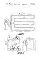
- FIG. 2is a schematic diagram of a controller and an electric blanket including a heat sensitive electrical sensor of the present invention.
- FIGS. 3 and 5are sectioned, perspective views of alternate embodiments of an electrical heating means and a heat sensitive conductor of the present invention parallel to one another.
- FIG. 7is a sectioned, perspective view of an alternate embodiment of the electrical heating means and a heat sensitive conductor of the present invention coaxial to one another.
- FIG. 9is a sectioned, perspective view of an alternative embodiment of the heat sensitive conductor of the present invention.
- FIGS. 4, 6, 8 and 10are sectioned views taken, respectively, along the lines 4--4 of FIG. 3, lines 6--6 of FIG. 5, lines 8--8 of FIG. 7, and lines 10--10 of FIG. 9.
- an electrical heating apparatus 2such as an electrically heated blanket, includes an envelope 4, an electrical heating means 6, a heat sensitive conductor 8, and a control means 9.
- the envelope 4may be fabric, plastic, or any other material that is suitable for use with an electrical heating apparatus. It may include channels or tunnels (not shown) to contain or position the electrical heating means 6 or heat sensitive conductor 8, or it may be comprised of two layers laminated or stitched together, as necessary or desirable.
- the control means 9includes a plug P for insertion into a standard wall outlet, a temperature control knob K which is adjusted to select a desired temperature level, and a control circuit C which includes suitable thermal mechanical or solid state switching means for controlling the electrical current flowing to the heating means 6 if an overheating condition is sensed.
- FIG. 1illustrates a suitable control circuit C which utilizes a normally open thermal switch 32 for controlling the flow of electrical energy to the heating means 6, and in which the heat sensitive conductor 8 has positive temperature coefficient (PTC) electrical impedence characteristics.
- the control circuit Ccould similarly utilize semiconductor switching devices, wherein the enabling or gate current for a triac, silicon controlled rectifier, diac, or the like, may be passed through the heat sensitive conductor 8. See FIG. 2 for a suitable solid state controller circuit.
- the semiconductor switchwill modulate downward the current flowing through the heating means 6 as the temperature of the heat sensitive conductor increases, and cease to conduct when the temperature of the heat sensitive conductor increases to some higher level.
- the control means 9includes a solid state control circuit C shown within the dotted lines.
- An electrical heating apparatus 2 protected against an overheating conditionis connected to the control means 9 by a suitable connector 10.
- the control means 9includes a standard plug P for insertion into a wall outlet.
- an on-off switch 11for manual operation by the user as a master switch.
- a manually operable temperature control 12having a knob 13, a bimetallic leaf switch contact 14, and a compensating heater 15.
- An alternate temperature controlis disclosed in U.S. Pat. No. 3,588,446.
- quadracis a bistable semiconductor device triggered through an integral diac and which can block voltage in either direction, conduct current in either direction, and be triggered for conducting current in either direction by the application of gate signals.
- the basic switch structuretypically includes a terminal MT 1 and an adjacent gate terminal G located on one side of the device, and a terminal MT 2 on the opposite side. The region of the semiconductor between the terminals MT 1 and MT 2 is in the form of a pair of parallel semiconductor switches.
- the gate terminalis indicated by a line emanating from the MT 1 side of the schematic symbol and including, within the envelope of the device, complementary triangular symbols indicating the diac or diode characteristic of the gate portion of the device.
- Terminal MT 1is the reference point for measurement of voltages and currents at the gate terminal G and at the opposite terminal MT 2 .
- the MT 1 terminal side of the switchis often regarded as the "front" of the device and the MT 2 terminal side of the quadrac is regarded as the "back" of the device.
- this terminologyis used in the present description and claims in order to specify the interconnection of the pair of switches.
- the pair of gate controlled bidirectional semiconductor switches provided in accordance with the present inventionare electrically connected to one another in series and in front-to-front orientation. That is, the MT 1 terminal sides of the devices are directly joined, with the MT 2 terminal sides serving to connect the switches in series relation with the electrical resistance heating means 6.
- the heat sensitive conductor 8is connected in series between the gate G of one semiconductor switch 17 and the MT 2 terminal of the other semiconductor switch 16.
- the heat sensitive conductoris a PTC material having an electrical impedance that increases with an increase in temperature. If an overheating condition occurs, the impedance increases and reduces the current flow through the sensor wire to the gate G.
- the current flow to the electrical heating meansmay be modulated or blocked, permitting the heating means to cool to a safer temperature.
- the heat sensitive conductorconsists of a single conductor, which greatly simplifies the control circuit, permits use of a less expensive connector 10, and minimizes the number of wires in the electrical heating apparatus.
- the gate G of semiconductor switch 16may be connected through a suitable biasing resistor 20 to allow triggering in a normal fashion.
- FIGS. 3-10illustrate alternate embodiments of the electrical heating means and heat sensitive conductor of the present invention.
- the electrical heating means 6includes a central core 27, such as an electrically nonconductive textile strand or other material to provide mechanical strength to the heating means.
- the physical and mechanical characteristics of the core 27may be chosen, as desirable, to limit its flexibility, thereby avoiding kinks or bends that might tend to break or knot the heating means.
- a known resistance heater wire 28is wrapped around the central core in a helix, and it provides heat when electrical current flows therethrough.
- An electrically insulating jacket 29coaxially surrounds the heater wire and central core.
- the thermodynamic properties of the insulating jacket 29may vary as necessary to suit a particular application or to match the thermodynamic properties or location of the temperature sensing means.
- the mechanical and physical propertiesmay vary as desirable to minimize cutting, chafing or the like.
- the heat sensitive conductor 8which does not have to be parallel to the heating means 6, includes a central core 32, such as an electrically nonconductive textile strand or other material, to provide mechanical strength in a manner similar to core 27.
- a conductor 33 having an electrical impedance proportional to temperatureis coaxially disposed by extrusion or otherwise around the core material 32.
- the change in impedance for each degree of change in temperaturemay also vary as necessary or desirable to be compatible with the control means 9 or to provide the desired sensitivity for the control means.
- a suitable material for a positive temperature coefficient materialmay include a thermoplastic material to which carbon has been added, and such a sensor wire may be suitable for extrusion manufacturing.
- thermoplastic materialexhibits a low impedance at lower temperatures and a higher impedance at higher temperatures.
- An electrically insulating jacket 34coaxially surrounds the conductor 33.
- the thermodynamic properties of the insulating jacketmay vary as necessary to suit a particular application. For instance, if the electrical heating means 6 and temperature sensing means 8 are in close proximity or are in the same channel in the blanket, the insulation may have more thermodynamic resistance than if the two are separated by one or more thicknesses of fabric.
- the heat sensitive conductoris preferably substantially coextensive with said heating means to provide a continuous, uninterrupted temperature sensitive overheating protection system, unlike the localized, discrete sensors used in the prior art. And, by placing the temperature sensing means in a fixed spaced relationship with respect to the heating means, the accuracy and uniformity of the temperature sensing and overheating detection is significantly enhanced. Suitable embodiments are illustrated in FIGS. 5-8.
- a parallel, unitary heater-sensor 40is illustrated, and it includes an electrical heating means 40A and a heat sensitive conductor 40B.
- a pair of core strands or yarns 41, 42are disposed in a fixed, spaced parallel relationship.
- Core strand 41is wrapped with a helix of electrically conductive heater wire 43, and core strand 42 is coaxially encased by a heat sensitive conductor 44.
- An electrically insulating outer casing 45maintains the heater wire-core strand combination 41, 43 in a fixed, spaced parallel relationship with respect to the heat sensitive conductor-core yarn combination 42, 44.
- this spacingmay result in a predetermined thermal relationship between the two conductors along their entire length, but the spacing is not critical.
- a coaxial unitary heater-sensor wire 50is illustrated, and it includes an electrical heating means 50A and a heat sensitive conductor 50B.
- a central core 51such as a textile strands or yarn, is wrapped on the outer surface thereof with a helix of conducting heater wire 52, which functions as a conventional heating element.
- a layer of electrical insulation 53coaxially encases the conductor 52 and core 51.
- a heat sensitive conductor 54coaxially encases the electrical insulation 53, and another layer of electrical insulation 55 coaxially encases the heat sensitive conductor 54.
- the radial thickness of the insulating layer 53may provide a fixed, selected spacing between the heater wire 52 and heat sensitive conductor 54, resulting in a predetermined thermal relationship between the two for uniformity of operation throughout the entire length of the heater-sensor wire.
- an alternate embodiment heat sensitive conductor 60is illustrated. It includes a central core 61 of yarn or other suitable material as described earlier.
- a heat sensitive conductor 62 having a positive temperature impedance coefficientis coaxially disposed around the core material. If it is desired to raise the conductivity in a local region or over a selected length of the conductor, a conductive material 63 may be applied to the surface of the conductor at predetermined spaced intervals. Suitable materials may include conductive paint, film, braid or wire.
- An electrically insulating jacket 64coaxially surrounds the heat sensitive conductor 62, any conductive overlays 63, and the core 61.
Landscapes
- Engineering & Computer Science (AREA)
- Textile Engineering (AREA)
- Control Of Resistance Heating (AREA)
- Resistance Heating (AREA)
Abstract
Description
Claims (29)
Priority Applications (4)
| Application Number | Priority Date | Filing Date | Title |
|---|---|---|---|
| US06/539,083US4577094A (en) | 1983-10-05 | 1983-10-05 | Electrical heating apparatus protected against an overheating condition |
| GB08424680AGB2148679B (en) | 1983-10-05 | 1984-10-01 | Electrical heating apparatus protected against an overheating condition |
| JP59208999AJPS6097590A (en) | 1983-10-05 | 1984-10-04 | Electric heater for preventing overheated state |
| CA000464720ACA1225426A (en) | 1983-10-05 | 1984-10-04 | Electrical heating apparatus protected against an overheating condition |
Applications Claiming Priority (1)
| Application Number | Priority Date | Filing Date | Title |
|---|---|---|---|
| US06/539,083US4577094A (en) | 1983-10-05 | 1983-10-05 | Electrical heating apparatus protected against an overheating condition |
Publications (1)
| Publication Number | Publication Date |
|---|---|
| US4577094Atrue US4577094A (en) | 1986-03-18 |
Family
ID=24149690
Family Applications (1)
| Application Number | Title | Priority Date | Filing Date |
|---|---|---|---|
| US06/539,083Expired - Fee RelatedUS4577094A (en) | 1983-10-05 | 1983-10-05 | Electrical heating apparatus protected against an overheating condition |
Country Status (4)
| Country | Link |
|---|---|
| US (1) | US4577094A (en) |
| JP (1) | JPS6097590A (en) |
| CA (1) | CA1225426A (en) |
| GB (1) | GB2148679B (en) |
Cited By (47)
| Publication number | Priority date | Publication date | Assignee | Title |
|---|---|---|---|---|
| US4891500A (en)* | 1987-09-05 | 1990-01-02 | Bloore Frederick W | Self-healing parallel heating tape |
| US4894513A (en)* | 1988-07-05 | 1990-01-16 | Ppg Industries, Inc. | Heatable windshield temperature control |
| US5064997A (en)* | 1984-07-10 | 1991-11-12 | Raychem Corporation | Composite circuit protection devices |
| US5089688A (en)* | 1984-07-10 | 1992-02-18 | Raychem Corporation | Composite circuit protection devices |
| US5148005A (en)* | 1984-07-10 | 1992-09-15 | Raychem Corporation | Composite circuit protection devices |
| US5261352A (en)* | 1991-10-28 | 1993-11-16 | Joseph Stammelman | Heated place for animals |
| US5541803A (en)* | 1994-03-07 | 1996-07-30 | Pope, Jr.; Ralph E. | Electrical safety device |
| US5726850A (en)* | 1996-07-24 | 1998-03-10 | Rowe, Jr.; William M. | Fail safe protection circuit for PTC comfort devices |
| US5801914A (en)* | 1996-05-23 | 1998-09-01 | Sunbeam Products, Inc. | Electrical safety circuit with a breakable conductive element |
| US5841617A (en)* | 1997-04-07 | 1998-11-24 | Bpw, Inc. | Electrical safety device with conductive polymer sensor |
| US5844759A (en)* | 1995-05-26 | 1998-12-01 | David C. Nemir | Electrical fault interrupter |
| US5862030A (en)* | 1997-04-07 | 1999-01-19 | Bpw, Inc. | Electrical safety device with conductive polymer sensor |
| US5973896A (en)* | 1995-05-26 | 1999-10-26 | David C. Nemir | Shock and arc protection device for an electrical distribution system |
| DE19827374A1 (en)* | 1998-06-19 | 1999-12-30 | Daimler Chrysler Ag | Safety fuse device for motor vehicle |
| US6153856A (en)* | 1997-01-21 | 2000-11-28 | Lee; Myoung Jun | Low magnetic field emitting electric blanket |
| US6160246A (en)* | 1999-04-22 | 2000-12-12 | Malden Mills Industries, Inc. | Method of forming electric heat/warming fabric articles |
| US6175098B1 (en)* | 1998-10-31 | 2001-01-16 | Solco Biomedical Co., Ltd. | Plane heating element without electromagnetic waves and a manufacturing method thereof |
| US6226450B1 (en) | 1997-01-21 | 2001-05-01 | Myoung Jun Lee | Electric field shielding apparatus |
| US6300597B1 (en) | 1997-01-21 | 2001-10-09 | Myoung Jun Lee | Electromagnetic field shielding electric heating pad |
| US6373034B1 (en) | 1999-04-22 | 2002-04-16 | Malden Mills Industries, Inc. | Electric heating/warming fabric articles |
| US6414286B2 (en) | 1999-04-22 | 2002-07-02 | Malden Mills Industries, Inc. | Electric heating/warming fibrous articles |
| US20020117494A1 (en)* | 1999-04-22 | 2002-08-29 | Moshe Rock | Fabric with heated circuit printed on intermediate film |
| US6512444B1 (en)* | 1997-12-10 | 2003-01-28 | B.P.W., Inc. | Fault sensing wire and alarm apparatus |
| US6548789B1 (en) | 1999-04-22 | 2003-04-15 | Malden Mills Industries, Inc. | Electric resistance heating/warming fabric articles |
| US20030178414A1 (en)* | 2000-10-27 | 2003-09-25 | Deangelis Alfred R. | Knitted thermal textile |
| US6713724B1 (en)* | 2002-10-11 | 2004-03-30 | Perfect Fit Industries, Inc. | Heating element arrangement for an electric blanket or the like |
| US6768086B2 (en) | 2002-07-08 | 2004-07-27 | Sunbeam Products, Inc. | Temperature sensor for a warming blanket |
| US20040156158A1 (en)* | 2003-02-08 | 2004-08-12 | David Walker | Reduced-volume commercial space heating system and method for manufacturing same |
| US6794610B2 (en)* | 2001-09-11 | 2004-09-21 | Sunbeam Products, Inc. | Heating blankets with low-current multiple heating elements |
| US20050004854A1 (en)* | 2002-09-30 | 2005-01-06 | Jones Emerson P. | Method and system for analyzing a capital structure for a company |
| ES2224854A1 (en)* | 2001-02-13 | 2005-03-01 | Especialidades Electricas Daga, S.A. | Control device for electric pillows and blankets, and similar elements |
| US20050067402A1 (en)* | 2003-09-30 | 2005-03-31 | Green Karen M. | Electrical connection of flexible conductive strands in a flexible body |
| US6888112B2 (en) | 1999-04-22 | 2005-05-03 | Malden Hills Industries, Inc. | Electric heating/warming woven fibrous articles |
| US20060049174A1 (en)* | 2003-09-30 | 2006-03-09 | Deangelis Alfred R | Regulated flexible heater |
| US7034251B1 (en) | 2005-05-18 | 2006-04-25 | Milliken & Company | Warming blanket |
| US7038170B1 (en) | 2005-01-12 | 2006-05-02 | Milliken & Company | Channeled warming blanket |
| US20060151475A1 (en)* | 2005-01-12 | 2006-07-13 | Horvath Joshua D | Channeled under floor heating element |
| US20060150331A1 (en)* | 2005-01-12 | 2006-07-13 | Child Andrew D | Channeled warming blanket |
| WO2006072765A1 (en)* | 2005-01-08 | 2006-07-13 | Thermocable (Flexible Elements) Limited | A controller for a heating cable |
| US20060151456A1 (en)* | 2005-01-12 | 2006-07-13 | Child Andrew D | Channeled warming mattress and mattress pad |
| US20060261055A1 (en)* | 2005-05-18 | 2006-11-23 | Child Andrew D | Warming mattress and mattress pad |
| US7193191B2 (en) | 2005-05-18 | 2007-03-20 | Milliken & Company | Under floor heating element |
| US20080055811A1 (en)* | 2006-08-10 | 2008-03-06 | O'rourke Kevin | Extension cord having a tempature indicator |
| US20080084268A1 (en)* | 2006-10-09 | 2008-04-10 | Weishe Zhang | Unrecoverable line-type temperature sensitive detector having short-circuit fault alarm function |
| US20080191833A1 (en)* | 2005-05-25 | 2008-08-14 | Callsmart Uk Limited | Thermal Protection For Electrical Installations and Fittings |
| US20110068098A1 (en)* | 2006-12-22 | 2011-03-24 | Taiwan Textile Research Institute | Electric Heating Yarns, Methods for Manufacturing the Same and Application Thereof |
| US8834198B2 (en) | 2006-08-10 | 2014-09-16 | Kevin O'Rourke | Electrical adaptor having a temperature indicator |
Families Citing this family (5)
| Publication number | Priority date | Publication date | Assignee | Title |
|---|---|---|---|---|
| US4849611A (en)* | 1985-12-16 | 1989-07-18 | Raychem Corporation | Self-regulating heater employing reactive components |
| US4677281A (en)* | 1986-11-04 | 1987-06-30 | Fieldcrest Cannon, Inc. | Electric heating apparatus with integrated solid state comfort control and overheat protection |
| US5191569A (en)* | 1989-05-15 | 1993-03-02 | Pioneer Electronic Corporation | Disk playback device |
| GB2235346B (en)* | 1989-08-25 | 1994-01-05 | Marconi Co Ltd | Radar receiver |
| DE202015002364U1 (en)* | 2015-03-30 | 2016-07-01 | I.G. Bauerhin Gmbh | Heating element for user-accessible surfaces |
Citations (4)
| Publication number | Priority date | Publication date | Assignee | Title |
|---|---|---|---|---|
| US3586831A (en)* | 1969-03-07 | 1971-06-22 | Hitachi Heating Appl | Heat response control circuit |
| US4315141A (en)* | 1980-09-05 | 1982-02-09 | Fieldcrest Mills, Inc. | Electrical heating apparatus with overheating protection |
| US4450496A (en)* | 1979-08-16 | 1984-05-22 | Raychem Corporation | Protection of certain electrical systems by use of PTC device |
| US4485296A (en)* | 1980-05-30 | 1984-11-27 | Matsushita Electric Industrial Co., Ltd. | Automatic temperature control device for an electric appliance such as an electric blanket |
Family Cites Families (11)
| Publication number | Priority date | Publication date | Assignee | Title |
|---|---|---|---|---|
| GB204603A (en)* | 1922-12-15 | 1923-10-04 | Frank Battey Pratt | An improved storage rack for the planes of aircraft and like goods |
| GB275293A (en)* | 1926-04-10 | 1927-08-10 | Rheostatic Co Ltd | Improved means for preventing electrical resistances from being overheated |
| GB338880A (en)* | 1929-05-18 | 1930-11-18 | Antonio Negromanti | Improvements in thermostatic devices for electrically heated fabrics |
| GB746017A (en)* | 1953-10-08 | 1956-03-07 | Gen Electric | Improvements relating to flexible electric heating cables |
| GB746018A (en)* | 1953-10-08 | 1956-03-07 | Gen Electric | Improvements relating to flexible electric heating cables |
| US3222497A (en)* | 1963-04-30 | 1965-12-07 | Gen Electric | Electrically heated bedcover |
| US3901952A (en)* | 1971-12-14 | 1975-08-26 | Matsushita Electric Industrial Co Ltd | Polymeric thermo-detective material |
| JPS5328821B2 (en)* | 1973-02-05 | 1978-08-17 | ||
| US4135179A (en)* | 1977-06-01 | 1979-01-16 | General Electric Company | Electrical temperature sensing device |
| GB1566005A (en)* | 1977-11-15 | 1980-04-30 | Dreamland Electrical Appliance | Heating circuits for electrically heated blankets or pads |
| JPS57872A (en)* | 1980-05-31 | 1982-01-05 | Matsushita Electric Works Ltd | Heater |
- 1983
- 1983-10-05USUS06/539,083patent/US4577094A/ennot_activeExpired - Fee Related
- 1984
- 1984-10-01GBGB08424680Apatent/GB2148679B/ennot_activeExpired
- 1984-10-04JPJP59208999Apatent/JPS6097590A/enactivePending
- 1984-10-04CACA000464720Apatent/CA1225426A/ennot_activeExpired
Patent Citations (4)
| Publication number | Priority date | Publication date | Assignee | Title |
|---|---|---|---|---|
| US3586831A (en)* | 1969-03-07 | 1971-06-22 | Hitachi Heating Appl | Heat response control circuit |
| US4450496A (en)* | 1979-08-16 | 1984-05-22 | Raychem Corporation | Protection of certain electrical systems by use of PTC device |
| US4485296A (en)* | 1980-05-30 | 1984-11-27 | Matsushita Electric Industrial Co., Ltd. | Automatic temperature control device for an electric appliance such as an electric blanket |
| US4315141A (en)* | 1980-09-05 | 1982-02-09 | Fieldcrest Mills, Inc. | Electrical heating apparatus with overheating protection |
Cited By (72)
| Publication number | Priority date | Publication date | Assignee | Title |
|---|---|---|---|---|
| US5089688A (en)* | 1984-07-10 | 1992-02-18 | Raychem Corporation | Composite circuit protection devices |
| US5148005A (en)* | 1984-07-10 | 1992-09-15 | Raychem Corporation | Composite circuit protection devices |
| US5064997A (en)* | 1984-07-10 | 1991-11-12 | Raychem Corporation | Composite circuit protection devices |
| US4891500A (en)* | 1987-09-05 | 1990-01-02 | Bloore Frederick W | Self-healing parallel heating tape |
| US4894513A (en)* | 1988-07-05 | 1990-01-16 | Ppg Industries, Inc. | Heatable windshield temperature control |
| US5261352A (en)* | 1991-10-28 | 1993-11-16 | Joseph Stammelman | Heated place for animals |
| US5541803A (en)* | 1994-03-07 | 1996-07-30 | Pope, Jr.; Ralph E. | Electrical safety device |
| USRE38714E1 (en)* | 1994-03-07 | 2005-03-22 | Pope Jr Ralph E | Electrical safety device |
| US5973896A (en)* | 1995-05-26 | 1999-10-26 | David C. Nemir | Shock and arc protection device for an electrical distribution system |
| US5844759A (en)* | 1995-05-26 | 1998-12-01 | David C. Nemir | Electrical fault interrupter |
| US5943198A (en)* | 1995-05-26 | 1999-08-24 | David C. Nemir | Electrical fault interrupt circuits |
| US5801914A (en)* | 1996-05-23 | 1998-09-01 | Sunbeam Products, Inc. | Electrical safety circuit with a breakable conductive element |
| US5726850A (en)* | 1996-07-24 | 1998-03-10 | Rowe, Jr.; William M. | Fail safe protection circuit for PTC comfort devices |
| US6226450B1 (en) | 1997-01-21 | 2001-05-01 | Myoung Jun Lee | Electric field shielding apparatus |
| US6153856A (en)* | 1997-01-21 | 2000-11-28 | Lee; Myoung Jun | Low magnetic field emitting electric blanket |
| US6300597B1 (en) | 1997-01-21 | 2001-10-09 | Myoung Jun Lee | Electromagnetic field shielding electric heating pad |
| US5841617A (en)* | 1997-04-07 | 1998-11-24 | Bpw, Inc. | Electrical safety device with conductive polymer sensor |
| US5862030A (en)* | 1997-04-07 | 1999-01-19 | Bpw, Inc. | Electrical safety device with conductive polymer sensor |
| US6801117B2 (en) | 1997-12-10 | 2004-10-05 | B.P.W., Inc. | Fault sensing wire and alarm apparatus |
| US6512444B1 (en)* | 1997-12-10 | 2003-01-28 | B.P.W., Inc. | Fault sensing wire and alarm apparatus |
| WO1999063637A1 (en)* | 1998-06-02 | 1999-12-09 | Bpw, Inc. | Electrical safety device with conductive polymer sensor |
| DE19827374A1 (en)* | 1998-06-19 | 1999-12-30 | Daimler Chrysler Ag | Safety fuse device for motor vehicle |
| DE19827374C2 (en)* | 1998-06-19 | 2001-05-23 | Daimler Chrysler Ag | Fuse element for electrical systems |
| US6175098B1 (en)* | 1998-10-31 | 2001-01-16 | Solco Biomedical Co., Ltd. | Plane heating element without electromagnetic waves and a manufacturing method thereof |
| US20020117494A1 (en)* | 1999-04-22 | 2002-08-29 | Moshe Rock | Fabric with heated circuit printed on intermediate film |
| US6963055B2 (en) | 1999-04-22 | 2005-11-08 | Malden Mills Industries, Inc. | Electric resistance heating/warming fabric articles |
| US6373034B1 (en) | 1999-04-22 | 2002-04-16 | Malden Mills Industries, Inc. | Electric heating/warming fabric articles |
| US6501055B2 (en) | 1999-04-22 | 2002-12-31 | Malden Mills Industries, Inc. | Electric heating/warming fabric articles |
| US6307189B1 (en) | 1999-04-22 | 2001-10-23 | Malden Mills Industries, Inc. | Electric heating/warming fabric articles |
| US6548789B1 (en) | 1999-04-22 | 2003-04-15 | Malden Mills Industries, Inc. | Electric resistance heating/warming fabric articles |
| US6852956B2 (en) | 1999-04-22 | 2005-02-08 | Malden Mills Industries, Inc. | Fabric with heated circuit printed on intermediate film |
| US6888112B2 (en) | 1999-04-22 | 2005-05-03 | Malden Hills Industries, Inc. | Electric heating/warming woven fibrous articles |
| US6160246A (en)* | 1999-04-22 | 2000-12-12 | Malden Mills Industries, Inc. | Method of forming electric heat/warming fabric articles |
| US6215111B1 (en)* | 1999-04-22 | 2001-04-10 | Malden Mills Industries, Inc. | Electric heating/warming fabric articles |
| US6414286B2 (en) | 1999-04-22 | 2002-07-02 | Malden Mills Industries, Inc. | Electric heating/warming fibrous articles |
| US7151062B2 (en) | 2000-10-27 | 2006-12-19 | Milliken & Company | Thermal textile |
| US20030208851A1 (en)* | 2000-10-27 | 2003-11-13 | Deangelis Alfred R. | Thermal textile |
| US20030178414A1 (en)* | 2000-10-27 | 2003-09-25 | Deangelis Alfred R. | Knitted thermal textile |
| ES2224854B1 (en)* | 2001-02-13 | 2005-12-16 | Especialidades Electricas Daga, S.A. | IMPROVEMENTS IN THE OBJECT OF THE MAIN PATENT N.200100313, BY CONTROL DEVICE FOR PADS, ELECTRICAL AND SIMILAR BLANKETS. |
| ES2224854A1 (en)* | 2001-02-13 | 2005-03-01 | Especialidades Electricas Daga, S.A. | Control device for electric pillows and blankets, and similar elements |
| US6794610B2 (en)* | 2001-09-11 | 2004-09-21 | Sunbeam Products, Inc. | Heating blankets with low-current multiple heating elements |
| US6768086B2 (en) | 2002-07-08 | 2004-07-27 | Sunbeam Products, Inc. | Temperature sensor for a warming blanket |
| US20050004854A1 (en)* | 2002-09-30 | 2005-01-06 | Jones Emerson P. | Method and system for analyzing a capital structure for a company |
| US6713724B1 (en)* | 2002-10-11 | 2004-03-30 | Perfect Fit Industries, Inc. | Heating element arrangement for an electric blanket or the like |
| US20040156158A1 (en)* | 2003-02-08 | 2004-08-12 | David Walker | Reduced-volume commercial space heating system and method for manufacturing same |
| US7138612B2 (en) | 2003-09-30 | 2006-11-21 | Milliken & Company | Electrical connection of flexible conductive strands in a flexible body |
| US20060151476A1 (en)* | 2003-09-30 | 2006-07-13 | Green Karen M | Electrical connection of flexible conductive strands in a flexible body |
| US7049557B2 (en) | 2003-09-30 | 2006-05-23 | Milliken & Company | Regulated flexible heater |
| US7064299B2 (en) | 2003-09-30 | 2006-06-20 | Milliken & Company | Electrical connection of flexible conductive strands in a flexible body |
| US20060049174A1 (en)* | 2003-09-30 | 2006-03-09 | Deangelis Alfred R | Regulated flexible heater |
| US20050067402A1 (en)* | 2003-09-30 | 2005-03-31 | Green Karen M. | Electrical connection of flexible conductive strands in a flexible body |
| US8173938B2 (en) | 2005-01-08 | 2012-05-08 | Thermocable (Flexible Elements) Limited | Controller for a heating cable |
| US20080251509A1 (en)* | 2005-01-08 | 2008-10-16 | Thomas Robst | Controller for a Heating Cable |
| WO2006072765A1 (en)* | 2005-01-08 | 2006-07-13 | Thermocable (Flexible Elements) Limited | A controller for a heating cable |
| US7180032B2 (en) | 2005-01-12 | 2007-02-20 | Milliken & Company | Channeled warming mattress and mattress pad |
| US20060151475A1 (en)* | 2005-01-12 | 2006-07-13 | Horvath Joshua D | Channeled under floor heating element |
| US20060150331A1 (en)* | 2005-01-12 | 2006-07-13 | Child Andrew D | Channeled warming blanket |
| US7193179B2 (en) | 2005-01-12 | 2007-03-20 | Milliken & Company | Channeled under floor heating element |
| US7038170B1 (en) | 2005-01-12 | 2006-05-02 | Milliken & Company | Channeled warming blanket |
| US20060151456A1 (en)* | 2005-01-12 | 2006-07-13 | Child Andrew D | Channeled warming mattress and mattress pad |
| US20060261055A1 (en)* | 2005-05-18 | 2006-11-23 | Child Andrew D | Warming mattress and mattress pad |
| US7034251B1 (en) | 2005-05-18 | 2006-04-25 | Milliken & Company | Warming blanket |
| US7189944B2 (en) | 2005-05-18 | 2007-03-13 | Milliken & Company | Warming mattress and mattress pad |
| US7193191B2 (en) | 2005-05-18 | 2007-03-20 | Milliken & Company | Under floor heating element |
| US20080191833A1 (en)* | 2005-05-25 | 2008-08-14 | Callsmart Uk Limited | Thermal Protection For Electrical Installations and Fittings |
| US7808761B2 (en)* | 2006-08-10 | 2010-10-05 | O'rourke Kevin | Extension cord having a temperature indicator |
| US20080055811A1 (en)* | 2006-08-10 | 2008-03-06 | O'rourke Kevin | Extension cord having a tempature indicator |
| US8834198B2 (en) | 2006-08-10 | 2014-09-16 | Kevin O'Rourke | Electrical adaptor having a temperature indicator |
| US9450348B2 (en) | 2006-08-10 | 2016-09-20 | Kevin O'Rourke | Electrical adaptor having a temperature indicator |
| US20080084268A1 (en)* | 2006-10-09 | 2008-04-10 | Weishe Zhang | Unrecoverable line-type temperature sensitive detector having short-circuit fault alarm function |
| US7671717B2 (en)* | 2006-10-19 | 2010-03-02 | Sureland Industrial Fire Safety Limited | Unrecoverable line-type temperature sensitive detector having short-circuit fault alarm function |
| US20110068098A1 (en)* | 2006-12-22 | 2011-03-24 | Taiwan Textile Research Institute | Electric Heating Yarns, Methods for Manufacturing the Same and Application Thereof |
Also Published As
| Publication number | Publication date |
|---|---|
| GB2148679A (en) | 1985-05-30 |
| GB2148679B (en) | 1987-10-28 |
| CA1225426A (en) | 1987-08-11 |
| GB8424680D0 (en) | 1984-11-07 |
| JPS6097590A (en) | 1985-05-31 |
Similar Documents
| Publication | Publication Date | Title |
|---|---|---|
| US4577094A (en) | Electrical heating apparatus protected against an overheating condition | |
| US4607154A (en) | Electrical heating apparatus protected against an overheating condition and a temperature sensitive electrical sensor for use therewith | |
| US6958463B1 (en) | Heater with simultaneous hot spot and mechanical intrusion protection | |
| US5861610A (en) | Heater wire with integral sensor wire and improved controller for same | |
| KR100586120B1 (en) | Electric blanket heating element | |
| US4198562A (en) | Electrically heated bedcover with overheat protective circuit | |
| US4547658A (en) | Multiple heat fusing wire circuit for underblankets | |
| US2782290A (en) | Temperature responsive control device | |
| CA2566564C (en) | Heater wire and control therefor | |
| US3628093A (en) | Thermostat overheat protection system for an electric appliance such as a blanket | |
| JPS63128579A (en) | Electric heater with one-piece temperature controller and overheat protector for solid body | |
| US3222497A (en) | Electrically heated bedcover | |
| US4278874A (en) | Heating circuits | |
| AU579881B2 (en) | Electric blankets | |
| US3814899A (en) | Overtemperature control system | |
| EP1645167B1 (en) | Heating blanket | |
| GB2083305A (en) | Electrical heating apparatus with overheating protection | |
| US4672176A (en) | Electric warmer | |
| CA1244863A (en) | Electric blanket or pad having improved positive temperature coefficient heater circuit | |
| US8173938B2 (en) | Controller for a heating cable | |
| US2959662A (en) | Thermosensitive protective system for electrically heated fabrics | |
| JPH04305716A (en) | Electric heating tool | |
| GB2157514A (en) | Electrical heating circuits | |
| JPH0684587A (en) | Thermosensitive heater | |
| JPH03226988A (en) | One-wire type heating temperature detecting wire |
Legal Events
| Date | Code | Title | Description |
|---|---|---|---|
| AS | Assignment | Owner name:FIELDCREST MILLS INC., EDEN, N.C., A DE CORP. Free format text:ASSIGNMENT OF ASSIGNORS INTEREST.;ASSIGNOR:MILLS, EDWIN R.;REEL/FRAME:004182/0267 Effective date:19830929 | |
| AS | Assignment | Owner name:FIRST NATIONAL BANK OF BOSTON THE Free format text:SECURITY INTEREST;ASSIGNOR:FIELDCREST MILLS, INC., A CORP OF DE.;REEL/FRAME:004558/0052 Effective date:19860130 | |
| AS | Assignment | Owner name:FIELD CREST CANNON, INC., Free format text:MERGER;ASSIGNORS:CANNON MILLS COMPANY, A NC CORP. (INTO);FIELDCREST MILLS, INC., A DE. CORP.;REEL/FRAME:004616/0487 Effective date:19860306 | |
| REMI | Maintenance fee reminder mailed | ||
| LAPS | Lapse for failure to pay maintenance fees | ||
| STCH | Information on status: patent discontinuation | Free format text:PATENT EXPIRED DUE TO NONPAYMENT OF MAINTENANCE FEES UNDER 37 CFR 1.362 | |
| FP | Lapsed due to failure to pay maintenance fee | Effective date:19900318 | |
| FEPP | Fee payment procedure | Free format text:PAYOR NUMBER ASSIGNED (ORIGINAL EVENT CODE: ASPN); ENTITY STATUS OF PATENT OWNER: LARGE ENTITY | |
| AS | Assignment | Owner name:FIELDCREST CANNON, INC, NORTH CAROLINA Free format text:TERMINATION, RELEASE AND ASSIGNMENT OF SECURITY INTEREST;ASSIGNOR:FIRST NATIONAL BANK OF BOSTON, THE. AS COLLATERAL AGENT;REEL/FRAME:008587/0093 Effective date:19970131 Owner name:FIELDCREST CANNON, INC, NORTH CAROLINA Free format text:TERMINATION, RELEASE AND ASSIGNMENT OF SECURITY INTEREST;ASSIGNOR:FIRST NATIONAL BANK OF BOSTON, THE, AS COLLATERAL AGENT;REEL/FRAME:008587/0093 Effective date:19970131 |