US4576539A - Wheelchair passenger lift apparatus for transit stations - Google Patents
Wheelchair passenger lift apparatus for transit stationsDownload PDFInfo
- Publication number
- US4576539A US4576539AUS06/571,903US57190384AUS4576539AUS 4576539 AUS4576539 AUS 4576539AUS 57190384 AUS57190384 AUS 57190384AUS 4576539 AUS4576539 AUS 4576539A
- Authority
- US
- United States
- Prior art keywords
- lift car
- bridge
- lift
- wheelchair
- upright
- Prior art date
- Legal status (The legal status is an assumption and is not a legal conclusion. Google has not performed a legal analysis and makes no representation as to the accuracy of the status listed.)
- Expired - Lifetime
Links
- 230000001681protective effectEffects0.000claimsdescription10
- 230000033001locomotionEffects0.000claimsdescription9
- 230000002441reversible effectEffects0.000claimsdescription7
- 238000010276constructionMethods0.000abstractdescription6
- 238000012163sequencing techniqueMethods0.000abstractdescription3
- 238000004904shorteningMethods0.000abstract1
- 230000007246mechanismEffects0.000description13
- 239000004020conductorSubstances0.000description4
- 239000012530fluidSubstances0.000description4
- 239000004606Fillers/ExtendersSubstances0.000description3
- 230000009471actionEffects0.000description3
- 230000008901benefitEffects0.000description3
- 230000009977dual effectEffects0.000description3
- 230000004044responseEffects0.000description3
- 230000008878couplingEffects0.000description2
- 238000010168coupling processMethods0.000description2
- 238000005859coupling reactionMethods0.000description2
- 230000006378damageEffects0.000description2
- -1polyethylenePolymers0.000description2
- 230000035939shockEffects0.000description2
- 239000004698PolyethyleneSubstances0.000description1
- 208000032369Primary transmissionDiseases0.000description1
- 239000004809TeflonSubstances0.000description1
- 229920006362Teflon®Polymers0.000description1
- 208000027418Wounds and injuryDiseases0.000description1
- 238000010521absorption reactionMethods0.000description1
- 230000001154acute effectEffects0.000description1
- 230000005540biological transmissionEffects0.000description1
- 230000008602contractionEffects0.000description1
- 238000010586diagramMethods0.000description1
- 238000007599dischargingMethods0.000description1
- 230000000977initiatory effectEffects0.000description1
- 208000014674injuryDiseases0.000description1
- 238000012423maintenanceMethods0.000description1
- 239000000463materialSubstances0.000description1
- 150000002730mercuryChemical class0.000description1
- 229910052753mercuryInorganic materials0.000description1
- 230000004048modificationEffects0.000description1
- 238000012986modificationMethods0.000description1
- 239000004033plasticSubstances0.000description1
- 229920003023plasticPolymers0.000description1
- 229920000573polyethylenePolymers0.000description1
- 229920001343polytetrafluoroethylenePolymers0.000description1
- 230000008439repair processEffects0.000description1
- 239000011435rockSubstances0.000description1
- 230000035945sensitivityEffects0.000description1
- 230000000087stabilizing effectEffects0.000description1
- BFKJFAAPBSQJPD-UHFFFAOYSA-NtetrafluoroetheneChemical compoundFC(F)=C(F)FBFKJFAAPBSQJPD-UHFFFAOYSA-N0.000description1
Images


Classifications
- A—HUMAN NECESSITIES
- A61—MEDICAL OR VETERINARY SCIENCE; HYGIENE
- A61G—TRANSPORT, PERSONAL CONVEYANCES, OR ACCOMMODATION SPECIALLY ADAPTED FOR PATIENTS OR DISABLED PERSONS; OPERATING TABLES OR CHAIRS; CHAIRS FOR DENTISTRY; FUNERAL DEVICES
- A61G3/00—Ambulance aspects of vehicles; Vehicles with special provisions for transporting patients or disabled persons, or their personal conveyances, e.g. for facilitating access of, or for loading, wheelchairs
- A61G3/02—Loading or unloading personal conveyances; Facilitating access of patients or disabled persons to, or exit from, vehicles
- A61G3/06—Transfer using ramps, lifts or the like
- A61G3/063—Transfer using ramps, lifts or the like using lifts separate from the vehicle, e.g. fixed on the pavement
- B—PERFORMING OPERATIONS; TRANSPORTING
- B66—HOISTING; LIFTING; HAULING
- B66F—HOISTING, LIFTING, HAULING OR PUSHING, NOT OTHERWISE PROVIDED FOR, e.g. DEVICES WHICH APPLY A LIFTING OR PUSHING FORCE DIRECTLY TO THE SURFACE OF A LOAD
- B66F7/00—Lifting frames, e.g. for lifting vehicles; Platform lifts
- B66F7/02—Lifting frames, e.g. for lifting vehicles; Platform lifts with platforms suspended from ropes, cables, or chains or screws and movable along pillars
- Y—GENERAL TAGGING OF NEW TECHNOLOGICAL DEVELOPMENTS; GENERAL TAGGING OF CROSS-SECTIONAL TECHNOLOGIES SPANNING OVER SEVERAL SECTIONS OF THE IPC; TECHNICAL SUBJECTS COVERED BY FORMER USPC CROSS-REFERENCE ART COLLECTIONS [XRACs] AND DIGESTS
- Y10—TECHNICAL SUBJECTS COVERED BY FORMER USPC
- Y10S—TECHNICAL SUBJECTS COVERED BY FORMER USPC CROSS-REFERENCE ART COLLECTIONS [XRACs] AND DIGESTS
- Y10S414/00—Material or article handling
- Y10S414/134—Handicapped person handling
Definitions
- This inventionrelates to an improved transit station lift apparatus by which wheelchair occupants and other disabled persons are given the means to enter and leave transit vehicles safely as regular passengers with minimum inconvenience and without undue time loss to the transit system.
- the inventionis herein illustratively described by reference to its presently preferred embodiment; however, it will be appreciated that certain modifications and changes therein may be made with respect to details without departing from the essential features involved.
- a further object of this inventionis to devise a relatively low-cost apparatus installed at the transit station or stop so as to serve all transit vehicles picking up and discharging passengers there including disabled passengers in wheelchairs.
- a related object hereofis to provide apparatus of this nature occupying a minimum of ground space at the transit station or stop and readily operable by the vehicle operator or conductor with the vehicle stopped to receive or discharge such passengers.
- a further and more specific object hereofis to devise such lift apparatus of relatively simple construction, essentially vandal-proof and provided with a control system restrictively accessible only by authorized persons such as a bus driver or conductor.
- a related purposeis to provide such apparatus with a control means conveniently operable from the vantage point of a transit vehicle entryway by a trained person such as a train conductor, thereby assuring that the most frail and most uncoordinated handicapped person in a wheelchair may safely and quickly board and leave the transit vehicle.
- Still another object hereofis to devise a lift apparatus easily accessed from either end and serving also as a safety enclosure available to the wheelchair occupant while waiting for arrival of the next train or bus vehicle and while being transferred between transit station platform and vehicle passenger deck.
- a related objectiveis to provide in such a lift apparatus an elevator system in which a normally retracted bridge, extendable to the vehicle passenger deck from the lift car platform, may be made of minimum projecting length deployed as a bridge so as to minimize the structural requirements of the bridge and the length of open span the wheelchair passenger must traverse in moving between lift car and transit vehicle deck.
- the wheelchair lift apparatuscomprises a lift car normally in lowered position with its platform boarding ramp at one end extended to the ground so as to accommodate a wheelchair passenger desiring to enter or leave.
- a bridge at the opposite end of the lift caris normally in upraised retracted position extending transversely between opposite side walls of the car so as to form therewith three sides of a protective enclosure.
- the bridgeis first raised, the lift car lowered to ground level, and the boarding ramp then extended from the lift car platform.
- both the lift car boarding ramp and bridgeare mounted for extension and retraction by hinging action employing side-mounted hydraulic jacks accommodated between dual panels of the lift car sidewalls.
- a cover or cowl over the jack operating the bridgetelescopes into the lower corner portion of the lift car side wall.
- a lift car elevator systemwith sloping guide tracks which advance the lift car horizontally toward the transit vehicle entryway as the lift car is being raised to passenger vehicle deck level position.
- Sliders supporting the lift carengage the sloping guide tracks in an arrangement also stabilizing and steadying the lift car in its movements up and down along the guide tracks.
- traveling sprockets carried by the sliders and commonly driven in rotation by interconnected lift car support shaftsengage and run on stationary sprocket chains.
- Such chainsheld stretched along the inclined guide tracks, engage two mutually adjacent sprockets on each slider in a double reversal of the chains as a means of providing a quietly smooth lift car device.
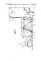
- FIG. 1is a side elevation of the lift apparatus with its lift car in lowered position and its ramp extended to the station platform for receiving a wheelchair passenger desiring to board the train as depicted in the view;
- FIG. 2is a side elevation similar to FIG. 1, but with the lift car partially elevated toward passenger transfer position;
- FIG. 3is a side elevation similar to FIG. 3, but with the lift car fully elevated to passenger transfer position, with its bridge extended to the train deck and with the wheelchair passenger shown boarding the train using the bridge;
- FIG. 4is a side elevation similar to FIG. 1, but at an enlarged scale, with parts broken away to show apparatus frame structure and lift car elevator guide tracks and drive mechanism;
- FIG. 5is a view similar to FIG. 3, and at the same scale as FIG. 4;
- FIG. 6is an end elevation of the apparatus appearing in FIG. 5 as viewed from the open entryway of the passenger train or other vehicle;
- FIG. 7is a plan view of the apparatus as shown in FIGS. 5 and 6;
- FIG. 8is a perspective view taken on line 8--8 in FIG. 7 illustrating a portion of the lift car elevator drive mechanism
- FIG. 9is a sectional view taken on line 9--9 in FIG. 8;
- FIG. 10is a perspective view of one corner of the lift car illustrating one end portion of the boarding ramp and the actuator means for extending and retracting the same;
- FIG. 11is a side elevation view showing the mechanism of FIG. 10;
- FIG. 12is a view of one corner of the lift car illustrating a portion of the bridge, the mechanism for extending and retracting the bridge, and a safety switch mounted along an end edge of the lift car side adjacent the bridge;
- FIG. 13is a side elevation showing the mechanism of FIG. 12;
- FIG. 14is a simplified functional block diagram of the control and sequencing means for operating the apparatus in the preferred manner
- FIG. 15is a schematic of the ramp and the means for actuating the same, along with switch means employed in the associated control system;
- FIG. 16is a schematic of the bridge and the means for extending and retracting the same, along with switch means employed in the associated control system.
- the lift apparatus for wheelchair passengersis depicted for use on a train station platform P.
- the trainis shown in the view by depicting its wheels W riding on tracks R extending parallel to the curb edge of the platform P and by its passenger steps S open in its open entryway leading upwardly to the passenger deck D.
- the lift apparatus Ais mounted adjacent to the edge of platform P oriented endwise toward the tracks.
- the widths of the entryways in most existing trains and other transit vehiclesare already sufficient or can be made sufficient to accommodate a wheelchair moved through the entryways.
- the lift apparatus bridge 10, which must be traversed by the wheelchair passenger in boarding and leaving the train,is made only a little wider than a wheelchair and is therefore extendable into the entryway with the lift car in its elevated passenger transfer position as depicted in FIG. 3.
- the span length of bridge 10is, of course, made sufficient to extend to the passenger deck D from the adjacent end of the lift platform 14 of lift car 12 with the lift car elevated.
- the lift car bridge 10 and ramp 16serve as end walls, and extend between opposite side walls 18 and 20 of the lift car (FIG. 6) to protectively surround the wheelchair occupant during raising and lowering of the lift car.
- Optional detailssuch as handrails 21 (FIG. 4) extending along the upper edges of the side walls 18 and 20 and other functional or aesthetic features may be employed suiting the engineering, appearance, and safety standards of the manufacturer and/or user.
- Lift car 12is mounted and guided to be raised and lowered by and between transversely spaced parallel upright frame wall structures 22 and 24, each with a pair of parallel lift car guide tracks 26 (FIG. 6).
- Lift car support sliders 28(FIG. 8) slidably engaging these tracks are themselves supported and driven in unison so as to maintain the lift platform always level as it is raised and lowered.
- Such guide tracksare inclined in parallel toward the train right-of-way at a substantial acute angle such as 75° relative to the station platform P.
- a short spansimplifies and economizes in the bridge structure needed to support load, and it also permits the train entryway to provide safe side and overhead shelter for the wheelchair passenger during crossing of the short bridge span.
- Lift car 12in more specific detail, comprises a hollow bottom structure with spaced top and bottom panels forming the lift platform 14.
- Upright side walls 18 and 20are appropriately joined with cantilever structural rigidity to opposite side edges of platform 14.
- Such side wallsare of dual-panel hollow construction, as are those of the apparatus support walls to be described, so as to accommodate functional components of the lift car such as hydraulic hoses, fittings, solenoid valves, motor switches and related components. These physical arrangements within the side walls are not important and may vary.
- bridge 10is preferably of hollow dual-panel construction with a beveled free end 10a and with side rails 10b. Hingedly mounted onto the end of the lift car by hinge fittings 30, the bridge is movable between extended or lowered position in which its then upper surface is substantially flush with the upper surface of the lift platform 14, and an upraised or retracted position in which its then outer or endwise facing surface is substantially flush with the end panels of the lift car sides.
- One such end panel 18ais shown in FIG. 12.
- hydraulic cylinder jack 32housed between the inner and outer panels 18b and 18c of lift car side wall 18, is pivotally mounted at one end on a fitting 34 fixed to the interior base of wall 18.
- a pivot pin 36mounted within a cowl or cover 38 at the base of bridge 10.
- the cover 38adjoins the outer side of bridge rail 10b and serves to minimize the open corner space which the extended piston rod of jack cylinder 32 encloses with the bridge extended.
- a notch or a slot in the transverse end plate 18a of side wall 18telescopingly accommodates the cowl 38 when the bridge is retracted by contraction of the hydraulic cylinder jack 32.
- the end edge of the inner wall 18bis provided with an elongated pressure sensitive edge switch 40 having switch elements (not shown) connected in the control system of the apparatus.
- This switchconstitutes a safety device of a well known type to arrest retraction of the bridge in the event a person or other obstacle is interposed between the retracting bridge and the end of car lift 18.
- a similar pressure switchis provided at the corresponding inner edge of the opposite wall 20.
- Such edgesare preferably set back inclined from the end plane of the side walls 18 and 20 so as to receive the tapered bridge retracted into a nested position between the outside panels of side walls 18 and 20 (FIG. 13).
- side wall end panel 18aand the corresponding end panel of the opposing side wall 20
- have a narrow vertical slot 18ewhich accommodates the plate-like bridge side rails 10b in the upraised position of the bridge.
- ramp 16is of dual panel hollow wedge-shaped cross-section with its uppermost panel terminating at its butt end substantially flush with the floor surface of lift platform 14 with the ramp in its lowered or extended position.
- Hinged on a set of fittings 50 fixed to the bottoms of the lift car sides 18 and 20, the ramp 16 in raised or retracted position (FIG. 5, for example)provides a low end gate or closure for the lift car.
- Hydraulic cylinder jack 52coupled by its base to a bracket 52b, is pivotally connected by its opposite end to the lug 56 upstanding from the base end of the ramp.
- the hydraulic cylinder jack 52is protectively housed within the hollow interior of one of the lift car side walls, in this instance the side wall 20.
- a hollow cowling or cover 16aencloses the portion of the hydraulic cylinder jack that protrudes from the car side wall 20 and is telescopingly received in the hollow of the side wall as the ramp is retracted.
- FIGS. 5 through 9The principal elements of elevator mechanism for raising and lowering the lift car are depicted in FIGS. 5 through 9.
- Slides 28guided for sliding movement lengthwise in the channel-shaped guide tracks, carry the lift car.
- Each slideris positionally stabilized relative to the car by positioning bars (not shown) which make the sliders rigidly integral with the car so that they are held against rocking or shifting relative to the car platform.
- Each such slidercomprises parallel plates of a synthetic plastic material such as polyethylene or polytetrafluorethylene (“TEFLON”) which may, but need not, be joined together by one or more blocks 28c spacing the plates apart to accommodate between them two chain sprockets 60 and 62 and the stretches of a sprocket chain 64 with which the respective sprockets are in running engagement.
- TEFLONpolyethylene or polytetrafluorethylene
- the chainis stretched under tension extending generally lengthwise along opposite interior flange faces of the guide channel 26.
- the upper end of the chainis anchored by a fitting 66 to the upper end of the channel flange nearest the lift car bridge.
- the opposite end of the chainis similarly anchored by a fitting 68 to the lower end of the opposite flange.
- Sprocket 60is rotatively journaled on shaft 60a extending through slider panels 28a and 28b.
- Sprocket 62is likewise rotatively journaled on and is keyed to shaft 62a as a drive shaft passing through slider panels 28a and 28b.
- shaft 62ais shown projecting through a gear housing 70 in which rotation of a drive shaft 72 by hydraulic motor 74 is converted into rotation of shaft 62a at right angles to shaft 72 through gearing (not shown) such as worm and wheel drive gearing, which is not reversible except when driven.
- gearingsuch as worm and wheel drive gearing, which is not reversible except when driven.
- a second transmission gear unit 76 driven by shaft 72converts rotation of the latter into rotation of shaft 78a.
- shaft 78aKeyed to elevator drive sprocket 78, shaft 78a is parallel to shaft 62a and terminates in a drive sprocket 78b in running engagement with a chain similar to chain 64 (FIG. 8).
- shaft 62aterminates in a drive sprocket 62b to which it is keyed and which likewise engages a stretched chain similar to chain 64.
- a shock absorption coupling 80is interposed between hydraulic drive motor 74 and the primary transmission drive gear unit 70, and a similar coupling 82 is likewise interposed between the output of such unit 70 and transfer shaft 72.
- shafts 62a and 78aare driven synchronously by the same mechanical drive power source (70) and the four corners of the lift car platform 14 are thereby maintained at the same height level above station platform P as the lift car is being raised and lowered between its terminal positions.
- While other forms of elevator mechanismsmay be employed, including other forms of chain and sprocket elevator mechanisms, that disclosed is preferred in its low-cost simplicity of construction, ready accessibility for maintenance and repairs and particularly in the quiet smoothness of starting and stopping of the lift car from the shock take-up action of the chains in their double reverse paths of encirclement around the adjacent sprocket.
- the apparatus base carrying the four inclined guide tracks 26comprises two parallel wall structures of hollow dual panel construction, also providing protective enclosure for various control and operating system components employed in the system.
- Such base wall structurescomprise upper horizontally disposed box beams 90 supported above bottom horizontal box beams 92 by the inclined guide rails and also by the diagonally but oppositely inclined brace members 94. Additional structural members 96 and 98 parallel to the guide tracks 26 add stiffness and strength.
- the box beams 92are bolted or otherwise rigidly secured to the station platform P at a distance separated sufficiently to accommodate the lift car and its associated drive mechanism (74, 70, 72, 76, etc.) between such base wall structures.
- a control tower 100Adjacent to the lift apparatus is a control tower 100 comprising an upright post mounted adjacent the edge of the station platform P and carrying a control head 102 with a normally covered access socket 104 at its upper end.
- this control head 102will be positioned about seven feet above the platform P so that the train operator or person who is to operate the lift apparatus from within the entryway of the train stopped in registry with the lift apparatus may reach out with a plug fitting 106 (FIG. 5) to connect the control head 102 to the control panel 108 in the passenger entryway of the train.
- Other meanssuch as radio or infrared control links may be used to permit operation of the apparatus from the transit vehicle.
- FIG. 14depicts the operational system preferably employed in practicing the invention in its preferred functional or sequencing mode.
- the systemincludes an electrical switch or equivalent means 110 operable from the control head by a manually or automatically initiated control signal to start the operation of a device 112 for retracting the ramp 16.
- the ramp 16is retracted by the hydraulic cylinder jack 52.
- Means 114senses the point at which the retracting ramp reaches a retracted position and preferably in such response actuates a ramp latch to hold the ramp in elevated or retracted position.
- the unit 114transmits a starting signal to the lift elevator drive energizing the hydraulic motor 74 to start raising the lift car substantially to passenger vehicle deck level.
- a response by unit 116stops the elevator drive and at the same time actuates a means 118 for releasing a bridge latch (not shown) and initiating operation of a bridge actuator 120 to lower or extend the bridge.
- Descent of the bridge to its extended or lowered positionis limited by its firm contact with vehicle deck D. This point is sensed by a means 122, to terminate operation of the bridge extender 120. If an obstruction prevents the bridge from reaching that lowered position, such as may occur if the passenger entryway of the train is not in correct registry with the lift apparatus, a unit 124 immediately terminates operation of the bridge extender mechanism 120 so as to avoid damage to equipment or injury to people. Preferably unit 124 is one and the same with unit 122.
- An overtravel sensor 121 in the form of a mercury switch mounted in the bridgeresponds to lowering of the bridge to an allowable limit such as 5 degrees below the horizontal to also terminate operation of mechanism 120.
- the retraction or return cycle of the lift apparatusis similarly initiated from the control head 102, in this instance by transmitting a cycle start signal to the means 126 which first initiates operation of the means 128 for retracting the bridge.
- this meanscomprises the hydraulic cylinder jack 32.
- Full retraction of the bridgesensed by the unit 130 actuates a bridge latch (not shown) to transmit a retraction stop signal to the retraction means 128. If an obstruction prevents the bridge from reaching its retracted position, either a unit 129 or one of the edge switches such as switch 40 immediately terminates operation of the retraction means 128.
- unit 130Upon full retraction of the bridge, unit 130 starts operation of the elevator drive 74 to lower the lift car.
- Suitable means 132senses arrival of the lift car at its lowered or platform level position and terminates the elevator drive operation. At the same time, it actuates the ramp latch release 134 and initiates operation of the ramp extension mechanism 136 (jack 52). A position sensor means 138 senses ramp extension and stops the operation of the ramp extender jack. The wheelchair lift car 12 and its entry ramp 16 are then in readiness to discharge or to receive a passenger. As previously indicated, bridge 10 has meanwhile been latched in its retracted or raised position and it remains there until the lift car is once again raised to train deck level.
- FIG. 15illustrates schematically the means controlling ramp operation.
- the base end of hydraulic cylinder jack 52has a pin 52a which is free to slide within an elongated slot in a bracket 52b secured to the base plate of platform 14 and within an elongated slot at one end of a link 52c whose other end is coupled by a pivotal mount 52d to a latch arm 52e that is pivotally mounted on the base plate of platform 14.
- a first extension spring 52fcouples the upper end of latch arm 52e to side wall 20 and urges latch arm 52e toward hydraulic cylinder 52.
- a second extension spring 52gcouples a portion of ramp 16 to side wall 20 and acts to restrain lowering of the ramp.
- Limit switch 52i on latch arm 52eserves to indicate, by whether its contacts are open or closed, that the ramp is either in its raised position and latched or it is not (the latter condition enabling the system to raise the ramp).
- hydraulic pressure fluidis delivered from a system pressure source through line 32a (FIG. 16) to the hydraulic cylinder jack 32 to extend the jack, such fluid passing through a flow restrictor 32b.
- the latterserves to provide a predetermined pressure differential thereacross when fluid is flowing through line 32a to extend the bridge 10.
- the resulting termination of fluid flow through line 32acauses the pressure differential across flow restrictor 32b to abruptly decrease so that the pressure at the lower side of flow restrictor 32b rises.
- This pressure riseis sensed by a hydraulic pressure switch 32c that performs the function of the unit 122 in FIG. 14.
- the inventionprovides a safe and practical, efficient apparatus by which wheelchair passengers and other disabled persons are enabled to use public transit facilities without undue interruption of transit schedules and even without regard to the capability of such persons to safely operate control mechanisms.
- the apparatusencourages wheelchair passengers to take a ready position in the lift car ready for boarding the train the instant it arrives at the station, and the lift apparatus can be accessed for operation by the train attendant. This it does by protecting the individual while in the lift car awaiting the arrival of the train, such as against the possibility of flying rocks or other debris, windrush, and the normal apprehensions that must occur to a disabled person in the close presence of such commotion.
- the apparatusis furthermore designed in such a way that severance of the connection to the control tower head 102 is disabling of all operating functions of the system such that children and vandals may not play with the apparatus when left unattended.
- the systemmay also be provided with added sensing apparatus positively holding the train braked or locked in standing position until the bridge 10 is retracted fully clear of the train entryway. Implementing this protection factor may be readily accomplished using any of existing state-of-art position detectors and train brake or drive controls responsive to the same so that the train control panel 108 held linked to the control head 106.
Landscapes
- Life Sciences & Earth Sciences (AREA)
- Health & Medical Sciences (AREA)
- Public Health (AREA)
- Engineering & Computer Science (AREA)
- Geology (AREA)
- Mechanical Engineering (AREA)
- Structural Engineering (AREA)
- Animal Behavior & Ethology (AREA)
- General Health & Medical Sciences (AREA)
- Veterinary Medicine (AREA)
- Vehicle Step Arrangements And Article Storage (AREA)
Abstract
Description
Claims (14)
Priority Applications (1)
| Application Number | Priority Date | Filing Date | Title |
|---|---|---|---|
| US06/571,903US4576539A (en) | 1984-01-17 | 1984-01-17 | Wheelchair passenger lift apparatus for transit stations |
Applications Claiming Priority (2)
| Application Number | Priority Date | Filing Date | Title |
|---|---|---|---|
| US06/571,903US4576539A (en) | 1984-01-17 | 1984-01-17 | Wheelchair passenger lift apparatus for transit stations |
| EP86300989AEP0236600A1 (en) | 1986-02-13 | 1986-02-13 | Wheelchair passenger lift apparatus for transit stations |
Publications (1)
| Publication Number | Publication Date |
|---|---|
| US4576539Atrue US4576539A (en) | 1986-03-18 |
Family
ID=26103665
Family Applications (1)
| Application Number | Title | Priority Date | Filing Date |
|---|---|---|---|
| US06/571,903Expired - LifetimeUS4576539A (en) | 1984-01-17 | 1984-01-17 | Wheelchair passenger lift apparatus for transit stations |
Country Status (1)
| Country | Link |
|---|---|
| US (1) | US4576539A (en) |
Cited By (53)
| Publication number | Priority date | Publication date | Assignee | Title |
|---|---|---|---|---|
| US4673328A (en)* | 1985-06-10 | 1987-06-16 | Shiels J Michael | Lift/tilt-bed trailer |
| EP0236600A1 (en)* | 1986-02-13 | 1987-09-16 | Lift-U-Inc. | Wheelchair passenger lift apparatus for transit stations |
| US4846458A (en)* | 1987-08-06 | 1989-07-11 | Tri-Tech, Inc. | Upper body exercise apparatus |
| US4904916A (en)* | 1988-05-18 | 1990-02-27 | The Cheney Company | Electrical control system for stairway wheelchair lift |
| US4926973A (en)* | 1988-12-09 | 1990-05-22 | Smith Dave W | Mobile wheelchair lift and brakes therefore |
| EP0381497A1 (en)* | 1989-02-01 | 1990-08-08 | Norman Dennis Eryou | Wheelchair loading device for aircarft |
| GB2236090A (en)* | 1989-09-09 | 1991-03-27 | Thomas John Carpenter | Portable vehicle access platform |
| US5105915A (en)* | 1990-12-24 | 1992-04-21 | Gary Jerry M | Wheelchair lifting device |
| US5110252A (en)* | 1990-05-24 | 1992-05-05 | Hogan Mfg., Inc. | Wheelchair lift for transit vehicles having elevated passenger compartment floor |
| USRE34212E (en)* | 1987-08-06 | 1993-04-06 | Tri-Tech, Inc. | Upper body exercise apparatus |
| US5205697A (en)* | 1991-04-19 | 1993-04-27 | Wollard Airport Equipment Company | Mobile passenger access lift |
| WO1993009747A1 (en)* | 1991-11-20 | 1993-05-27 | Paolo Filippo Variola | Lift with sliding pneumatic platform |
| US5224723A (en)* | 1992-05-26 | 1993-07-06 | Hatas Peter J | Vehicle step and platform apparatus |
| US5256117A (en)* | 1990-10-10 | 1993-10-26 | Stairmaster Sports Medical Products, Inc. | Stairclimbing and upper body, exercise apparatus |
| US5299904A (en)* | 1992-03-26 | 1994-04-05 | Hogan Mfg., Inc. | Vehicle lift with contact sensor |
| US5319818A (en)* | 1992-01-27 | 1994-06-14 | Baranowski Edwin M | Accessibility means for a person using a wheelchair |
| USRE34959E (en)* | 1986-08-04 | 1995-05-30 | Stairmaster Sports/Medical Products, Inc. | Stair-climbing exercise apparatus |
| US5499959A (en)* | 1991-04-15 | 1996-03-19 | Stairmaster Sports/Medical Products, Inc. | Upper body exercise apparatus |
| US5553990A (en)* | 1990-04-27 | 1996-09-10 | Kytola, Sr.; David | Hydraulic wheelchair lift |
| US5595470A (en)* | 1994-03-07 | 1997-01-21 | American Airlines, Incorporated | Lift for physically-challenged passengers and method of operation |
| US5632593A (en)* | 1996-04-26 | 1997-05-27 | Lift-U, Division Of Hogan Mfg., Inc. | Vehicle lift with tapered contact sensor |
| WO1999031324A1 (en)* | 1997-12-16 | 1999-06-24 | Flat White Pty. Ltd. | Access platform for wheelchairs |
| US5947231A (en)* | 1996-09-27 | 1999-09-07 | Raase Lifts | Pivoting wheel chair lift device |
| EP0986997A3 (en)* | 1998-09-15 | 2000-11-22 | Bestgroup Srl | Mobile device for disabled persons |
| US6182798B1 (en)* | 1994-07-26 | 2001-02-06 | Agm Container Controls, Inc. | Mobile lifting device for the disabled |
| WO2002018172A1 (en)* | 2000-09-01 | 2002-03-07 | Braun Corporation | Electronic controller for vehicular wheelchair access |
| US6692217B1 (en)* | 1999-04-29 | 2004-02-17 | The Braun Corporation | Liftable platform having isolated hydraulically-moveable rollstop |
| DE10255516A1 (en)* | 2002-11-27 | 2004-06-17 | Bernd Schneider | Ramp for moving e.g. wheelchair over steps has bracket which fits over step when it is in lower position and is raised as ramp is raised, e.g. using scissor mechanism |
| AU2004100643B4 (en)* | 2004-08-09 | 2005-05-12 | Mirko Riha | Platformramp |
| US20060182570A1 (en)* | 2004-12-30 | 2006-08-17 | Eric Zuercher | Portable wheel chair lift |
| US20070086879A1 (en)* | 2003-11-18 | 2007-04-19 | Ronald Goodrich | Electronic control system and method for an auxiliary device interlock safety system |
| US20080044268A1 (en)* | 2006-08-17 | 2008-02-21 | Heigl Keith D | Door and ramp interface system |
| US20080184623A1 (en)* | 2007-02-01 | 2008-08-07 | Heigl Keith D | Vehicle access control system |
| US20080257611A1 (en)* | 2005-10-05 | 2008-10-23 | Hamilton Edward C | Integrated Aircraft Scale and Leveling Apparatus and Methods for Use |
| US20080283320A1 (en)* | 2007-04-18 | 2008-11-20 | Dean Bowles | Motorized vehicle configured to accommodate handicapped individuals |
| US20080308357A1 (en)* | 2007-06-14 | 2008-12-18 | Coble James T Tim | Permanently-installed wheel chair lift with height control |
| US20080308358A1 (en)* | 2007-06-14 | 2008-12-18 | Eric Zuercher | Wheel chair lift with protective skirt sensors |
| US20100176618A1 (en)* | 2004-09-24 | 2010-07-15 | Stryker Corporation | In-ambulance cot shut-off device |
| US20100283581A1 (en)* | 2006-12-06 | 2010-11-11 | Heigl Keith D | Wireless vehicle access control system |
| US20110278096A1 (en)* | 2010-04-15 | 2011-11-17 | Walter Kentenich | Passenger Lift System with Access Control |
| US20110278516A1 (en)* | 2010-05-14 | 2011-11-17 | Brad Christian | Vehicle lift |
| ITPI20100104A1 (en)* | 2010-09-27 | 2012-03-28 | Mp S R L | METHOD FOR THE TRANSFER OF PEOPLE TO WHEELCHAIRS ON / FROM PUBLIC TRANSPORT MEANS. |
| US8540214B2 (en) | 2010-09-07 | 2013-09-24 | Brad Christian | Vehicle lift |
| USRE44884E1 (en) | 2004-09-24 | 2014-05-13 | Stryker Corporation | Ambulance cot with pinch safety feature |
| US8783419B2 (en) | 2011-11-03 | 2014-07-22 | Agm Container Controls, Inc. | Low profile wheelchair lift with direct-acting hydraulic cylinders |
| US20140248109A1 (en)* | 2013-03-01 | 2014-09-04 | Lift-U, Division Of Hogan Mfg., Inc. | Ramp assembly with tilt sensor |
| US20140328660A1 (en)* | 2009-06-03 | 2014-11-06 | Design Specific Ltd. | Compact Wheelchair Platform |
| US8973713B2 (en) | 2011-11-03 | 2015-03-10 | Agm Container Controls, Inc. | Height adjustment system for wheelchair lift |
| US9051156B2 (en) | 2011-11-03 | 2015-06-09 | Agm Container Controls, Inc. | Wheelchair lift device with pinned floor struts |
| RU170817U1 (en)* | 2016-10-10 | 2017-05-11 | Александр Николаевич Столбов | Wheelchair lifting device "Strongman" |
| JP2018177502A (en)* | 2017-04-19 | 2018-11-15 | 株式会社いうら | Wheelchair lift |
| CN114701983A (en)* | 2022-04-12 | 2022-07-05 | 诚通凯胜生态建设有限公司 | Be fit for old-fashioned landscape platform |
| TWI832683B (en)* | 2023-01-19 | 2024-02-11 | 博士門股份有限公司 | Lift trolley |
Citations (12)
| Publication number | Priority date | Publication date | Assignee | Title |
|---|---|---|---|---|
| US1634854A (en)* | 1924-07-02 | 1927-07-05 | Thomas F Scollard | Electric elevator |
| US2059059A (en)* | 1936-05-04 | 1936-10-27 | Globe Machinery & Supply Compa | Portable electric automobile hoist |
| US2702678A (en)* | 1950-09-23 | 1955-02-22 | Lockheed Aircraft Corp | Cargo loader for aircraft |
| US3229788A (en)* | 1963-06-25 | 1966-01-18 | Welded Products Inc | Invalid elevator |
| US3521775A (en)* | 1968-08-16 | 1970-07-28 | Howard H Vermette | Portable power lift |
| US3737009A (en)* | 1971-11-01 | 1973-06-05 | J Stoddard | Wheel chair lift |
| US3794193A (en)* | 1971-12-17 | 1974-02-26 | W Fleenor | Cargo handling mechanism |
| US3888463A (en)* | 1973-08-20 | 1975-06-10 | Brien Robert A O | Self-leveling hoist for wheel chairs |
| US3966022A (en)* | 1974-10-15 | 1976-06-29 | Cheney Robert W | Wheelchair lift assembly |
| US4063619A (en)* | 1976-11-08 | 1977-12-20 | Drews Robert E | Elevator platform structure |
| US4124100A (en)* | 1978-02-13 | 1978-11-07 | General Motors Corporation | Locking arrangement for wheelchair lift device |
| US4347030A (en)* | 1978-10-31 | 1982-08-31 | Kingston John C | Wheelchair loading device for trains |
- 1984
- 1984-01-17USUS06/571,903patent/US4576539A/ennot_activeExpired - Lifetime
Patent Citations (12)
| Publication number | Priority date | Publication date | Assignee | Title |
|---|---|---|---|---|
| US1634854A (en)* | 1924-07-02 | 1927-07-05 | Thomas F Scollard | Electric elevator |
| US2059059A (en)* | 1936-05-04 | 1936-10-27 | Globe Machinery & Supply Compa | Portable electric automobile hoist |
| US2702678A (en)* | 1950-09-23 | 1955-02-22 | Lockheed Aircraft Corp | Cargo loader for aircraft |
| US3229788A (en)* | 1963-06-25 | 1966-01-18 | Welded Products Inc | Invalid elevator |
| US3521775A (en)* | 1968-08-16 | 1970-07-28 | Howard H Vermette | Portable power lift |
| US3737009A (en)* | 1971-11-01 | 1973-06-05 | J Stoddard | Wheel chair lift |
| US3794193A (en)* | 1971-12-17 | 1974-02-26 | W Fleenor | Cargo handling mechanism |
| US3888463A (en)* | 1973-08-20 | 1975-06-10 | Brien Robert A O | Self-leveling hoist for wheel chairs |
| US3966022A (en)* | 1974-10-15 | 1976-06-29 | Cheney Robert W | Wheelchair lift assembly |
| US4063619A (en)* | 1976-11-08 | 1977-12-20 | Drews Robert E | Elevator platform structure |
| US4124100A (en)* | 1978-02-13 | 1978-11-07 | General Motors Corporation | Locking arrangement for wheelchair lift device |
| US4347030A (en)* | 1978-10-31 | 1982-08-31 | Kingston John C | Wheelchair loading device for trains |
Cited By (76)
| Publication number | Priority date | Publication date | Assignee | Title |
|---|---|---|---|---|
| US4673328A (en)* | 1985-06-10 | 1987-06-16 | Shiels J Michael | Lift/tilt-bed trailer |
| EP0236600A1 (en)* | 1986-02-13 | 1987-09-16 | Lift-U-Inc. | Wheelchair passenger lift apparatus for transit stations |
| USRE34959E (en)* | 1986-08-04 | 1995-05-30 | Stairmaster Sports/Medical Products, Inc. | Stair-climbing exercise apparatus |
| USRE34212E (en)* | 1987-08-06 | 1993-04-06 | Tri-Tech, Inc. | Upper body exercise apparatus |
| US4846458A (en)* | 1987-08-06 | 1989-07-11 | Tri-Tech, Inc. | Upper body exercise apparatus |
| US4904916A (en)* | 1988-05-18 | 1990-02-27 | The Cheney Company | Electrical control system for stairway wheelchair lift |
| US4926973A (en)* | 1988-12-09 | 1990-05-22 | Smith Dave W | Mobile wheelchair lift and brakes therefore |
| EP0381497A1 (en)* | 1989-02-01 | 1990-08-08 | Norman Dennis Eryou | Wheelchair loading device for aircarft |
| GB2236090A (en)* | 1989-09-09 | 1991-03-27 | Thomas John Carpenter | Portable vehicle access platform |
| US5553990A (en)* | 1990-04-27 | 1996-09-10 | Kytola, Sr.; David | Hydraulic wheelchair lift |
| US5110252A (en)* | 1990-05-24 | 1992-05-05 | Hogan Mfg., Inc. | Wheelchair lift for transit vehicles having elevated passenger compartment floor |
| US5256117A (en)* | 1990-10-10 | 1993-10-26 | Stairmaster Sports Medical Products, Inc. | Stairclimbing and upper body, exercise apparatus |
| US5105915A (en)* | 1990-12-24 | 1992-04-21 | Gary Jerry M | Wheelchair lifting device |
| US5540639A (en)* | 1991-04-15 | 1996-07-30 | Stairmaster Sports/Medical Products, Inc. | Device to prevent arcuate motion of a user assist platform for an upper body exercise apparatus |
| US5499959A (en)* | 1991-04-15 | 1996-03-19 | Stairmaster Sports/Medical Products, Inc. | Upper body exercise apparatus |
| US5205697A (en)* | 1991-04-19 | 1993-04-27 | Wollard Airport Equipment Company | Mobile passenger access lift |
| WO1993009747A1 (en)* | 1991-11-20 | 1993-05-27 | Paolo Filippo Variola | Lift with sliding pneumatic platform |
| US5319818A (en)* | 1992-01-27 | 1994-06-14 | Baranowski Edwin M | Accessibility means for a person using a wheelchair |
| US5299904A (en)* | 1992-03-26 | 1994-04-05 | Hogan Mfg., Inc. | Vehicle lift with contact sensor |
| US5224723A (en)* | 1992-05-26 | 1993-07-06 | Hatas Peter J | Vehicle step and platform apparatus |
| US5595470A (en)* | 1994-03-07 | 1997-01-21 | American Airlines, Incorporated | Lift for physically-challenged passengers and method of operation |
| US6062809A (en)* | 1994-03-07 | 2000-05-16 | American Airlines Incorporated | Lift for physically-challenged passengers and method of operation |
| US6182798B1 (en)* | 1994-07-26 | 2001-02-06 | Agm Container Controls, Inc. | Mobile lifting device for the disabled |
| US5632593A (en)* | 1996-04-26 | 1997-05-27 | Lift-U, Division Of Hogan Mfg., Inc. | Vehicle lift with tapered contact sensor |
| US5947231A (en)* | 1996-09-27 | 1999-09-07 | Raase Lifts | Pivoting wheel chair lift device |
| WO1999031324A1 (en)* | 1997-12-16 | 1999-06-24 | Flat White Pty. Ltd. | Access platform for wheelchairs |
| EP0986997A3 (en)* | 1998-09-15 | 2000-11-22 | Bestgroup Srl | Mobile device for disabled persons |
| US6419050B1 (en) | 1998-09-15 | 2002-07-16 | Bestgroup Srl | Mobile device for disabled persons |
| US6692217B1 (en)* | 1999-04-29 | 2004-02-17 | The Braun Corporation | Liftable platform having isolated hydraulically-moveable rollstop |
| US7798761B2 (en) | 2000-09-01 | 2010-09-21 | The Braun Corporation | Electronic control system and method for an auxiliary device interlock safety system |
| WO2002018172A1 (en)* | 2000-09-01 | 2002-03-07 | Braun Corporation | Electronic controller for vehicular wheelchair access |
| US20110008141A1 (en)* | 2000-09-01 | 2011-01-13 | Ronald Goodrich | Electronic control system and method for an auxiliary device interlock safety system |
| US20090271077A1 (en)* | 2000-09-01 | 2009-10-29 | Ronald Goodrich | Electronic control system and method for an auxiliary device interlock safety system |
| DE10255516A1 (en)* | 2002-11-27 | 2004-06-17 | Bernd Schneider | Ramp for moving e.g. wheelchair over steps has bracket which fits over step when it is in lower position and is raised as ramp is raised, e.g. using scissor mechanism |
| DE10255516B4 (en)* | 2002-11-27 | 2006-02-09 | Bernd Schneider | Stationary lifting device, in particular for wheelchairs and mobile transport aids, and method for overcoming a staircase-like obstacle |
| US20070086879A1 (en)* | 2003-11-18 | 2007-04-19 | Ronald Goodrich | Electronic control system and method for an auxiliary device interlock safety system |
| AU2004100643B4 (en)* | 2004-08-09 | 2005-05-12 | Mirko Riha | Platformramp |
| USRE44884E1 (en) | 2004-09-24 | 2014-05-13 | Stryker Corporation | Ambulance cot with pinch safety feature |
| US20100176618A1 (en)* | 2004-09-24 | 2010-07-15 | Stryker Corporation | In-ambulance cot shut-off device |
| US8056950B2 (en) | 2004-09-24 | 2011-11-15 | Stryker Corporation | In-ambulance cot shut-off device |
| US20060182570A1 (en)* | 2004-12-30 | 2006-08-17 | Eric Zuercher | Portable wheel chair lift |
| US8739935B2 (en) | 2004-12-30 | 2014-06-03 | Agm Container Controls, Inc. | Portable wheel chair lift |
| US20110174579A1 (en)* | 2004-12-30 | 2011-07-21 | Agm Container Controls, Inc. | Portable wheel chair lift |
| US7926618B2 (en) | 2004-12-30 | 2011-04-19 | Agm Container Controls, Inc. | Portable wheel chair lift |
| US20080257611A1 (en)* | 2005-10-05 | 2008-10-23 | Hamilton Edward C | Integrated Aircraft Scale and Leveling Apparatus and Methods for Use |
| US7838782B2 (en)* | 2005-10-05 | 2010-11-23 | Bell Helicopter Textron Inc. | Integrated aircraft scale and leveling apparatus and methods for use |
| US7551995B2 (en) | 2006-08-17 | 2009-06-23 | The Braun Corporation | Door and ramp interface system |
| US20090259371A1 (en)* | 2006-08-17 | 2009-10-15 | Heigl Keith D | Door and ramp interface system |
| US20080044268A1 (en)* | 2006-08-17 | 2008-02-21 | Heigl Keith D | Door and ramp interface system |
| US7978119B2 (en) | 2006-12-06 | 2011-07-12 | Heigl Keith D | Wireless vehicle access control system |
| US20100283581A1 (en)* | 2006-12-06 | 2010-11-11 | Heigl Keith D | Wireless vehicle access control system |
| US20080184623A1 (en)* | 2007-02-01 | 2008-08-07 | Heigl Keith D | Vehicle access control system |
| US7816878B2 (en) | 2007-02-01 | 2010-10-19 | The Braun Corporation | Vehicle access control system |
| US20080283320A1 (en)* | 2007-04-18 | 2008-11-20 | Dean Bowles | Motorized vehicle configured to accommodate handicapped individuals |
| US7823674B2 (en)* | 2007-04-18 | 2010-11-02 | Dean Bowles | Motorized vehicle configured to accommodate handicapped individuals |
| US7721850B2 (en) | 2007-06-14 | 2010-05-25 | Agm Container Controls, Inc. | Permanently-installed wheel chair lift with height control |
| US8079447B2 (en) | 2007-06-14 | 2011-12-20 | Agm Container Controls, Inc. | Wheel chair lift with protective skirt sensors |
| US20080308358A1 (en)* | 2007-06-14 | 2008-12-18 | Eric Zuercher | Wheel chair lift with protective skirt sensors |
| US20080308357A1 (en)* | 2007-06-14 | 2008-12-18 | Coble James T Tim | Permanently-installed wheel chair lift with height control |
| US20140328660A1 (en)* | 2009-06-03 | 2014-11-06 | Design Specific Ltd. | Compact Wheelchair Platform |
| US9445962B2 (en)* | 2009-06-03 | 2016-09-20 | Design Specific, Ltd. | Compact wheelchair platform |
| US20110278096A1 (en)* | 2010-04-15 | 2011-11-17 | Walter Kentenich | Passenger Lift System with Access Control |
| US20110278516A1 (en)* | 2010-05-14 | 2011-11-17 | Brad Christian | Vehicle lift |
| US8540214B2 (en) | 2010-09-07 | 2013-09-24 | Brad Christian | Vehicle lift |
| ITPI20100104A1 (en)* | 2010-09-27 | 2012-03-28 | Mp S R L | METHOD FOR THE TRANSFER OF PEOPLE TO WHEELCHAIRS ON / FROM PUBLIC TRANSPORT MEANS. |
| WO2012042458A1 (en)* | 2010-09-27 | 2012-04-05 | Mp S.R.L. | Method for the transfer of people on wheel-chair on/from public transport means |
| US8783419B2 (en) | 2011-11-03 | 2014-07-22 | Agm Container Controls, Inc. | Low profile wheelchair lift with direct-acting hydraulic cylinders |
| US8973713B2 (en) | 2011-11-03 | 2015-03-10 | Agm Container Controls, Inc. | Height adjustment system for wheelchair lift |
| US9051156B2 (en) | 2011-11-03 | 2015-06-09 | Agm Container Controls, Inc. | Wheelchair lift device with pinned floor struts |
| US9271883B2 (en)* | 2013-03-01 | 2016-03-01 | Lift-U, Division Of Hogan Mfg., Inc. | Ramp assembly with tilt sensor |
| US20140248109A1 (en)* | 2013-03-01 | 2014-09-04 | Lift-U, Division Of Hogan Mfg., Inc. | Ramp assembly with tilt sensor |
| RU170817U1 (en)* | 2016-10-10 | 2017-05-11 | Александр Николаевич Столбов | Wheelchair lifting device "Strongman" |
| JP2018177502A (en)* | 2017-04-19 | 2018-11-15 | 株式会社いうら | Wheelchair lift |
| CN114701983A (en)* | 2022-04-12 | 2022-07-05 | 诚通凯胜生态建设有限公司 | Be fit for old-fashioned landscape platform |
| CN114701983B (en)* | 2022-04-12 | 2024-04-09 | 诚通凯胜生态建设有限公司 | Suitable old type landscape platform |
| TWI832683B (en)* | 2023-01-19 | 2024-02-11 | 博士門股份有限公司 | Lift trolley |
Similar Documents
| Publication | Publication Date | Title |
|---|---|---|
| US4576539A (en) | Wheelchair passenger lift apparatus for transit stations | |
| US4071152A (en) | Wheelchair lift for public transportation vehicle | |
| US4058228A (en) | Passenger vehicle access stair and elevator apparatus | |
| US5832555A (en) | Compact moveable ramp assembly | |
| US5425615A (en) | Combination folding stair and platform wheelchair lift | |
| US7802337B2 (en) | Retractable ramp | |
| US4438830A (en) | Stairway with fail safe power lift for lading, the infirm, wheelchair patients, and the like | |
| US4251179A (en) | Wheelchair lift | |
| CA1159793A (en) | Lift for handicapped persons for a rail car | |
| US5105914A (en) | Stairlift | |
| US10589754B2 (en) | Train platform located security system | |
| WO1996026848A1 (en) | An improved movable ramp assembly | |
| US5230288A (en) | Entering and exiting step system for vehicles with swingable platform for wheelchair bound passengers | |
| US4039091A (en) | Elevator type bus boarder | |
| EP0236600A1 (en) | Wheelchair passenger lift apparatus for transit stations | |
| US4394837A (en) | Passenger station for elevated railway system | |
| JPH02204160A (en) | Covering of cap between platform and train | |
| KR101495326B1 (en) | Ferry boat with boarding equipment for traffic weaker | |
| JP2723444B2 (en) | Wheelchair embarkation equipment | |
| KR101701391B1 (en) | Safety foothold for train platform | |
| CA2557420A1 (en) | Automatic baggage lift leveling and lift system and apparatus for supporting same from a movable structure such as a jet bridge | |
| US20020074188A1 (en) | Installation for transporting people, in particular those with reduced mobility, and fitting of this installation from notably an escalator | |
| KR200368582Y1 (en) | a safety device for a subway station | |
| RU175479U1 (en) | A lifting device for boarding and alighting a passenger in a wheelchair, installed in a railway carriage | |
| KR100654914B1 (en) | Leveling device and wheelchair lift with him |
Legal Events
| Date | Code | Title | Description |
|---|---|---|---|
| AS | Assignment | Owner name:LIFT-U-INC., 8206 S. 192ND ST., KENT, WA 98032, A Free format text:ASSIGNMENT OF ASSIGNORS INTEREST.;ASSIGNOR:WILLIAMS, HAROLD R.;REEL/FRAME:004223/0680 Effective date:19840116 | |
| STCF | Information on status: patent grant | Free format text:PATENTED CASE | |
| CC | Certificate of correction | ||
| AS | Assignment | Owner name:HOGAN MANUFACTURING, INC., A CA. CORP. Free format text:ASSIGNMENT OF ASSIGNORS INTEREST.;ASSIGNOR:LIFT-U-INC.,;REEL/FRAME:004766/0110 Effective date:19870817 | |
| AS | Assignment | Owner name:HOGAN MANUFACTURING, INC., A CA. CORP. Free format text:ASSIGNMENT OF ASSIGNORS INTEREST.;ASSIGNOR:LIFT-U-INC.,;REEL/FRAME:004772/0632 Effective date:19870921 Owner name:HOGAN MANUFACTURING, INC. Free format text:ASSIGNMENT OF ASSIGNORS INTEREST;ASSIGNOR:LIFT-U-INC.,;REEL/FRAME:004772/0632 Effective date:19870921 | |
| FEPP | Fee payment procedure | Free format text:PAYOR NUMBER ASSIGNED (ORIGINAL EVENT CODE: ASPN); ENTITY STATUS OF PATENT OWNER: SMALL ENTITY | |
| FPAY | Fee payment | Year of fee payment:4 | |
| FEPP | Fee payment procedure | Free format text:PAYER NUMBER DE-ASSIGNED (ORIGINAL EVENT CODE: RMPN); ENTITY STATUS OF PATENT OWNER: SMALL ENTITY Free format text:PAYOR NUMBER ASSIGNED (ORIGINAL EVENT CODE: ASPN); ENTITY STATUS OF PATENT OWNER: SMALL ENTITY | |
| FPAY | Fee payment | Year of fee payment:8 | |
| FPAY | Fee payment | Year of fee payment:12 |