US4576181A - Disposable pressure transducer apparatus for medical use - Google Patents
Disposable pressure transducer apparatus for medical useDownload PDFInfo
- Publication number
- US4576181A US4576181AUS06/608,761US60876184AUS4576181AUS 4576181 AUS4576181 AUS 4576181AUS 60876184 AUS60876184 AUS 60876184AUS 4576181 AUS4576181 AUS 4576181A
- Authority
- US
- United States
- Prior art keywords
- substrate
- pressure
- pressure transducer
- passageway
- housing
- Prior art date
- Legal status (The legal status is an assumption and is not a legal conclusion. Google has not performed a legal analysis and makes no representation as to the accuracy of the status listed.)
- Expired - Fee Related
Links
- 239000000758substrateSubstances0.000claimsabstractdescription106
- 239000012530fluidSubstances0.000claimsabstractdescription32
- 230000036772blood pressureEffects0.000claimsabstractdescription24
- 238000012544monitoring processMethods0.000claimsabstractdescription24
- 230000008878couplingEffects0.000claimsdescription23
- 238000010168coupling processMethods0.000claimsdescription23
- 238000005859coupling reactionMethods0.000claimsdescription23
- 239000004020conductorSubstances0.000claimsdescription16
- 238000009530blood pressure measurementMethods0.000claimsdescription14
- 239000000463materialSubstances0.000claimsdescription14
- 229910000679solderInorganic materials0.000claimsdescription14
- 239000011248coating agentSubstances0.000claimsdescription13
- 238000000576coating methodMethods0.000claimsdescription13
- 229920000915polyvinyl chloridePolymers0.000claimsdescription12
- 239000004800polyvinyl chlorideSubstances0.000claimsdescription12
- 239000012212insulatorSubstances0.000claimsdescription10
- 229920001296polysiloxanePolymers0.000claimsdescription10
- 239000000126substanceSubstances0.000claimsdescription6
- 208000027418Wounds and injuryDiseases0.000claimsdescription4
- 230000006378damageEffects0.000claimsdescription4
- 208000014674injuryDiseases0.000claimsdescription4
- 238000004891communicationMethods0.000claims5
- 238000013022ventingMethods0.000claims5
- 239000004065semiconductorSubstances0.000abstractdescription27
- 238000000034methodMethods0.000description20
- 238000004519manufacturing processMethods0.000description9
- 239000000853adhesiveSubstances0.000description8
- 230000001070adhesive effectEffects0.000description8
- XUIMIQQOPSSXEZ-UHFFFAOYSA-NSiliconChemical compound[Si]XUIMIQQOPSSXEZ-UHFFFAOYSA-N0.000description7
- 210000004204blood vesselAnatomy0.000description7
- UQMRAFJOBWOFNS-UHFFFAOYSA-Nbutyl 2-(2,4-dichlorophenoxy)acetateChemical compoundCCCCOC(=O)COC1=CC=C(Cl)C=C1ClUQMRAFJOBWOFNS-UHFFFAOYSA-N0.000description7
- 230000001052transient effectEffects0.000description7
- 229910052710siliconInorganic materials0.000description6
- 239000010703siliconSubstances0.000description6
- RZVAJINKPMORJF-UHFFFAOYSA-NAcetaminophenChemical compoundCC(=O)NC1=CC=C(O)C=C1RZVAJINKPMORJF-UHFFFAOYSA-N0.000description5
- 230000008602contractionEffects0.000description5
- 230000007246mechanismEffects0.000description5
- NJPPVKZQTLUDBO-UHFFFAOYSA-NnovaluronChemical compoundC1=C(Cl)C(OC(F)(F)C(OC(F)(F)F)F)=CC=C1NC(=O)NC(=O)C1=C(F)C=CC=C1FNJPPVKZQTLUDBO-UHFFFAOYSA-N0.000description5
- 239000005297pyrexSubstances0.000description5
- 230000035939shockEffects0.000description5
- 238000005259measurementMethods0.000description4
- 238000012216screeningMethods0.000description3
- 230000035945sensitivityEffects0.000description3
- 208000028399Critical IllnessDiseases0.000description2
- FAPWRFPIFSIZLT-UHFFFAOYSA-MSodium chlorideChemical compound[Na+].[Cl-]FAPWRFPIFSIZLT-UHFFFAOYSA-M0.000description2
- 238000005452bendingMethods0.000description2
- 210000004369bloodAnatomy0.000description2
- 239000008280bloodSubstances0.000description2
- 230000008859changeEffects0.000description2
- 238000001514detection methodMethods0.000description2
- 238000011161developmentMethods0.000description2
- 230000018109developmental processEffects0.000description2
- 238000001990intravenous administrationMethods0.000description2
- 238000002955isolationMethods0.000description2
- 230000000737periodic effectEffects0.000description2
- 229920003023plasticPolymers0.000description2
- 239000004033plasticSubstances0.000description2
- 238000003466weldingMethods0.000description2
- 206010053567CoagulopathiesDiseases0.000description1
- HTTJABKRGRZYRN-UHFFFAOYSA-NHeparinChemical compoundOC1C(NC(=O)C)C(O)OC(COS(O)(=O)=O)C1OC1C(OS(O)(=O)=O)C(O)C(OC2C(C(OS(O)(=O)=O)C(OC3C(C(O)C(O)C(O3)C(O)=O)OS(O)(=O)=O)C(CO)O2)NS(O)(=O)=O)C(C(O)=O)O1HTTJABKRGRZYRN-UHFFFAOYSA-N0.000description1
- 206010034960PhotophobiaDiseases0.000description1
- 238000004458analytical methodMethods0.000description1
- 230000004872arterial blood pressureEffects0.000description1
- 238000004500asepsisMethods0.000description1
- 230000005540biological transmissionEffects0.000description1
- 230000017531blood circulationEffects0.000description1
- 230000005792cardiovascular activityEffects0.000description1
- 230000005800cardiovascular problemEffects0.000description1
- 229910010293ceramic materialInorganic materials0.000description1
- 238000003486chemical etchingMethods0.000description1
- 230000035602clottingEffects0.000description1
- 238000010276constructionMethods0.000description1
- 238000001723curingMethods0.000description1
- 230000001419dependent effectEffects0.000description1
- 239000003989dielectric materialSubstances0.000description1
- 230000002526effect on cardiovascular systemEffects0.000description1
- 238000005516engineering processMethods0.000description1
- 239000003822epoxy resinSubstances0.000description1
- 230000005284excitationEffects0.000description1
- 239000011521glassSubstances0.000description1
- 229960002897heparinDrugs0.000description1
- 229920000669heparinPolymers0.000description1
- 230000006872improvementEffects0.000description1
- 238000001746injection mouldingMethods0.000description1
- 239000011810insulating materialSubstances0.000description1
- 238000009413insulationMethods0.000description1
- 150000002500ionsChemical class0.000description1
- 210000004731jugular veinAnatomy0.000description1
- 208000013469light sensitivityDiseases0.000description1
- 238000012423maintenanceMethods0.000description1
- QSHDDOUJBYECFT-UHFFFAOYSA-NmercuryChemical compound[Hg]QSHDDOUJBYECFT-UHFFFAOYSA-N0.000description1
- 229910052753mercuryInorganic materials0.000description1
- 239000000615nonconductorSubstances0.000description1
- 230000000149penetrating effectEffects0.000description1
- 210000005259peripheral bloodAnatomy0.000description1
- 239000011886peripheral bloodSubstances0.000description1
- 229920000647polyepoxidePolymers0.000description1
- 230000008569processEffects0.000description1
- 210000002321radial arteryAnatomy0.000description1
- 239000013464silicone adhesiveSubstances0.000description1
- 239000000243solutionSubstances0.000description1
- 238000012414sterilization procedureMethods0.000description1
- 210000001321subclavian veinAnatomy0.000description1
Images


Classifications
- G—PHYSICS
- G01—MEASURING; TESTING
- G01L—MEASURING FORCE, STRESS, TORQUE, WORK, MECHANICAL POWER, MECHANICAL EFFICIENCY, OR FLUID PRESSURE
- G01L19/00—Details of, or accessories for, apparatus for measuring steady or quasi-steady pressure of a fluent medium insofar as such details or accessories are not special to particular types of pressure gauges
- G01L19/0007—Fluidic connecting means
- G01L19/0023—Fluidic connecting means for flowthrough systems having a flexible pressure transmitting element
- A—HUMAN NECESSITIES
- A61—MEDICAL OR VETERINARY SCIENCE; HYGIENE
- A61B—DIAGNOSIS; SURGERY; IDENTIFICATION
- A61B5/00—Measuring for diagnostic purposes; Identification of persons
- A61B5/02—Detecting, measuring or recording for evaluating the cardiovascular system, e.g. pulse, heart rate, blood pressure or blood flow
- A61B5/021—Measuring pressure in heart or blood vessels
- A61B5/0215—Measuring pressure in heart or blood vessels by means inserted into the body
- A—HUMAN NECESSITIES
- A61—MEDICAL OR VETERINARY SCIENCE; HYGIENE
- A61B—DIAGNOSIS; SURGERY; IDENTIFICATION
- A61B2562/00—Details of sensors; Constructional details of sensor housings or probes; Accessories for sensors
- A61B2562/02—Details of sensors specially adapted for in-vivo measurements
- A61B2562/0247—Pressure sensors
Definitions
- This inventionrelates to pressure transducers for medical use and, more particularly, to a novel, disposable pressure transducer apparatus for use in the direct measurement and/or monitoring of human blood pressure.
- blood pressure measurement and monitoringare frequently employed with patients suffering from shock or cardiovascular ailments.
- medical personnelare better able to detect blood flow difficulties and other cardiovascular problems at an early stage.
- the use of blood pressure measurement and monitoringmay increase the likelihood that a patient can be successfully treated and/or provided with needed emergency assistance.
- a variety of methodsare currently used for measuring and/or monitoring blood pressure. For example, medical personnel frequently use various indirect blood pressure measurement techniques, such as measuring a patient's blood pressure by using a pressure cuff and a stethoscope.
- blood pressure measurementsare often made using a number of direct measurement and monitoring techniques.
- direct techniquesare greatly preferred over any of the indirect techniques.
- direct blood pressure measurement and monitoringgreatly increases the accuracy of the blood pressure reading.
- Typical indirect techniquesmay, for example, yield errors as high as ten percent, whereas direct blood pressure measurement and monitoring techniques are generally accurate to within about one percent.
- direct monitoring techniquesfacilitate the continuous monitoring of a patient's blood pressure on a beat-to-beat basis.
- Direct blood pressure monitoringalso enables the rapid detection of a change in cardiovascular activity, and this may be of significant importance in emergency situations.
- direct blood pressure monitoring techniquescan be readily used to measure and monitor a patient's blood pressure at a specific internal location, such as within the chambers of the heart. Because of these and other advantages, therefore, direct blood pressure measurement and monitoring has become part of the routine treatment for critically ill patients.
- catheterizationOne of the most widely used techniques for direct blood pressure measurement and monitoring is called catheterization.
- a needleis first inserted into a peripheral blood vessel. For example, if it is desired to monitor arterial blood pressure, the needle may be inserted into the radial artery. If, on the other hand, venous blood pressure is to be monitored, the needle may be inserted into the antecubital, radial, jugular, or subclavian veins.
- a special catheteris threaded through the needle and into the blood vessel.
- this catheteris filled with some type of solution, such as, for example, a sterile saline solution.
- the cathetermay be formed so as to facilitate the further threading of the catheter along the blood vessel.
- the cathetermay be threaded through the needle and along the blood vessel until the tip of the catheter, which is located inside the blood vessel, is positioned at the particular point within the body at which it is desired to make the blood pressure measurement. Then, with the catheter thus in place, the needle may be withdrawn.
- the indwelling catheterAfter the indwelling catheter is positioned within a patient as described above, the other end of the catheter is connected to pressure transducer.
- the catheteris generally also connected to a suitable continuous flush device or heparin drip to help prevent clotting around the tip of the catheter.
- the present transduceris then connected to some type of monitor device near the patient's bedside. Typical monitor devices include cathode ray tube display devices, digital display and/or recording devices, printers and plotters.
- any air bubbles within the catheterare next removed such that a continuous fluid column is provided from the pressure transducer to the tip of the catheter which is located within the patient's blood vessel.
- periodic pressure pulsesare transmitted through the patient's blood vessels and along the fluid column in the catheter to the pressure transducer.
- the pressure transducergenerates electrical signals representing the pressure pulses, and such signals are then amplified and displayed by the monitor device.
- the monitor deviceis used to display the patient's blood pressure as a function of time, this type of display being commonly referred to as the blood pressure waveform.
- a patient's blood pressure waveformcan then be used by medical personnel to appropriately diagnose and treat the patient.
- the pressure transducerone of the most important components of the above-described blood pressure monitoring system is the pressure transducer.
- the accuracy and reliability of the pressure transducerset an upper limit to the quality of the blood pressure data which can be obtained. Therefore, those skilled in the art of blood pressure monitoring have attempted to develop pressure transducers which have a high degree of reliability, sensitivity, and accuracy.
- a typical pressure transducer for use in blood pressure monitoring systemscomprises a thin diaphragm which is capable of being deflected by the pressure pulses which travel through the above-described fluid column in the catheter.
- Some type of mechanismis also provided for measuring the deflection of the diaphragm; and such a measuring mechanism usually comprises suitable electronic circuitry which is configured so as to generate an electrical signal representing the pressure exerted on the diaphragm.
- a resistive strain gaugecomprises a thin resistive wire which is connected to the pressure diaphragm such that the wire is stretched whenever the diaphragm is deflected.
- a stretching of the wirecauses the electrical resistance of the wire to increase.
- a constant voltageis being applied across the wire, such an increase in the wire's resistance will result in a corresponding decrease in the electrical current through the wire in accordance with Ohm's law.
- the prior art deviceshave typically included some type of temperature compensation circuitry.
- Such circuitrymay comprise resistors, thermistors, or other electrical components which are designed to compensate for fluctuations in the transducer output which are caused by variations in temperature.
- temperature compensation circuitrymay be located in a number of positions relative to the pressure diaphragm.
- one prior art deviceprovides the temperature compensation circuitry as part of a connector in a cable which is used to connect the transducer device to an external monitor.
- the prior art deviceshave also attempted to compensate for the light sensitivity of semiconductors in a number of ways.
- some prior art devicesinclude a coating on the semiconductor transducer which is intended to shield the transducer from exposure to light.
- the prior art devicesmay additionally comprise some type of tinted plastic housing which surrounds the transducer. Such a tinted housing is also intended to shield the semiconductor transducer from light.
- pyrexhas approximately the same coefficient of thermal expansion as silicon.
- the pyrex pedestalwill expand and contract with variations in temperature in substantially the same manner as in silicon chip, thereby minimizing mechanical stress which may be caused by such thermal expansion and contraction.
- Such insulatorsmay, for example, comprise part of a housing within which the electronic circuitry is contained.
- the prior art disposable pressure transducersrepresent an important improvement over the earlier reusable transducers, a number of significant difficulties remain.
- the prior art disposable pressure transducersare not entirely effective in shielding the semiconductor transducer from exposure to light.
- the prior art devicessometimes produce incorrect transient pressure readings which may interfere with the subsequent analysis and use of the pressure data.
- a movement of the prior art deviceswill occasionally subject the sensitive pressure measuring circuitry to mechanical stress, thereby also producing transient fluctuations in the pressure readings. Because of these conditions, therefore, the prior art disposable pressure transducer devices will sometimes not produce data having the desired degree of accuracy.
- the prior art disposable pressure transducersare typically quite complex, and they remain, therefore, relatively expensive to manufacture.
- a number of separate, delicate assembly stepsare often required in order to arrange the various components of the transducer devices into a single unit.
- Such assembly stepsmay, for example, include mounting a semiconductor transducer on a pyrex pedestal and thereafter securing the pedestal within a housing.
- assembly stepsmay, for example, include mounting a semiconductor transducer on a pyrex pedestal and thereafter securing the pedestal within a housing.
- the expense of manufacturing the prior art transducer devicesincreases the ultimate cost of the devices; and such increased cost makes it less desirable to dispose of the devices after only a single use.
- an object of the present inventionto provide a disposable pressure transducer apparatus wherein the semiconductor transducer of the apparatus is effectively shielded from exposure to light.
- the present inventionis directed to a novel disposable pressure transducer apparatus for monitoring human blood pressure.
- the apparatuscomprises a two-sided dielectric substrate sheet which has a hole therethrough.
- a semiconductor pressure transduceris mounted directly to one side of the dielectric substrate such that the portion of the transducer which forms the piezoresistive pressure diaphragm is positioned over the hole in the substrate.
- the pressure transduceris mounted to the substrate such that it is free to thermally expand and contract without being subjected to mechanical stress.
- the pressure transduceris also covered by an opaque cap which prevents light from contacting the transducer.
- at least one side of the dielectric substratemay be coated with an opaque substance to further shield the semiconductor transducer from light.
- a temperature compensation circuitalso is provided on the substrate by some suitable means, such as, for example, by silk-screening; and the substrate further has solder pads secured thereto for electrically connecting the circuit on the substrate to a monitor device.
- the pressure transducer, the opaque cap, the temperature compensation circuit, and the solder padsare all positioned on the same side of the dielectric substrate sheet, thereby greatly facilitating manufacture and assembly of the apparatus.
- the substratetogether with the above-mentioned components, is secured within a housing.
- the housingis provided with a fluid coupling passageway for connecting the housing to a catheter, and a second passageway extends from the fluid coupling passageway so as to communicate through the hole in the substrate with the pressure transducer.
- Both the second passageway through the housing and the hole in the substrateare filled with a silicone gel such that pressure pulses may be transmitted through the silicone gel to the pressure transducer.
- the silicone gelextends into the space between the housing and the dielectric substrate so as to form a fluid-tight seal, thereby providing electrical isolation of the transducer apparatus from the patient.
- a portion of the silicone gelmay also be opaque so as to help further shield the semiconductor transducer from exposure to light.
- FIG. 1is a perspective view illustrating one presently preferred embodiment of the disposable pressure transducer apparatus of the present invention.
- FIG. 2is a partially exploded perspective view illustrating one presently preferred embodiment of the disposable pressure transducer apparatus of the present invention.
- FIG. 3is a cross-sectional view taken along lines 3--3 of FIG. 1.
- FIG. 4is a cross-sectional view taken along lines 4--4 of FIG. 1.
- FIG. 5is an enlarged, cross-sectional view taken along lines 5--5 of FIG. 4.
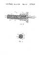
- FIG. 6is an enlarged, cross-sectional view taken along lines 6--6 of FIG. 2 and illustrating one presently preferred embodiment of a cable for connecting the disposable pressure transducer apparatus of the present invention to a monitor device.
- FIG. 7is an enlarged, cross-sectional view taken along lines 7--7 of FIG. 2.
- housing 12is provided with a fluid coupling tube 20 which may be connected to a catheter (not shown).
- a cable 14extends from housing 12 and serves to carry electrical signals which represent the pressure measurements made by transducer apparatus 10 to a monitor (not shown).
- a catheterwhich is inserted into a blood vessel of a patient is connected to coupling tube 20 of transducer apparatus 10. Pressure pulses from such patient's blood stream are then transmitted through the fluid column in the catheter through the passageway of coupling tube 20.
- the pressure detection components within housing 12detect and measure the pressure pulses and generate electrical signals representing such pulses.
- the generated electrical signalsare then transmitted along cable 14 to a monitor (not shown) such that the pressure data may be appropriately displayed and/or recorded.
- FIGS. 1 and 2One presently preferred configuration for housing 12 of transducer apparatus 10 is illustrated in FIGS. 1 and 2.
- coupling tube 20 of housing 12is provided with suitable connectors for connecting coupling tube 20 to an indwelling, fluid-filled catheter (not shown).
- These connectorsmay comprise virtually any suitable connectors, such as standard luer lock connectors.
- coupling tube 20is illustrated herein as having a luer lock nut 24 attached to one end 22 thereof, while the other end 26 of coupling tube 20 is configured as a threaded female luer lock connector.
- Housing 12may advantageously comprise some means for mounting transducer apparatus 10 to the arm of a patient or to another structure.
- housing 12may comprise a pair of mounting brackets 30 which are either secured to or formed integrally with housing 12.
- mounting brackets 30may also have slots 32 formed therein through which tape or straps may be positioned to secure the housing.
- transducer apparatus 10can be mounted to an I.V. poll, to a fluid manifold adjacent the patient's bedside, or to the patient himself.
- Housing 12may be configured in any suitable manner.
- housing 12may comprise a shell 40 and a back plate 50.
- shell 40may be provided with a recessed shelf 42, and back plate 50 may be formed so as to fit snugly within recessed shelf 42.
- Back plate 50may then be secured to shell 40 in some suitable manner, such as, for example, by means of an adhesive or by sonic welding.
- housing 12 of transducer apparatus 10could also have a wide variety of different shapes.
- housing 12is illustrated herein as being a substantially cubical structure, it will be appreciated that housing 12 could also be formed as a substantially cylindrical or ellipsoid structure.
- housing 12could be formed as part of another intravenous device.
- housing 12could be formed as part of an intravenous continuous flush device.
- housing 12may have any suitable dimensions. Preferably, however, housing 12 is relatively small so as to both reduce manufacturing costs and allow a patient substantial freedom of movement when transducer apparatus 10 is attached directly to such patient. Thus, for example, one presently preferred embodiment of housing 12 is approximately one inch (2.54 cm) wide, 1.5 inches (3.81 cm) long, and 0.5 inch (1.27 cm) deep.
- housing 12may be formed of a wide variety of substances.
- housing 12may be formed of a suitable plastic material by conventional injection molding techniques.
- housing 12may be formed so as to be at least partially transparent.
- the various electrical components of transducer apparatus 10are secured within housing 12. As shown, such electrical components are mounted on a dielectric substrate sheet 70.
- Substrate 70may be formed of any of a number of suitable dielectric materials, such as, for example, a ceramic material.
- Substrate 70is, in turn, secured within housing 12.
- housing 12may be provided with suitable stakes 44 which may be flattened by means of sonic welding techniques over a portion of substrate 70 after substrate 70 is appropriately positioned within housing 12 between the stakes 44 (see also FIG. 3).
- substrate 70is provided with a conventional temperature compensation circuit 72.
- Temperature compensation circuit 72is used to adjust both the zero pressure point and the gain of transducer apparatus 10 such that these parameters will not change with variations in temperature. Temperature compensation circuit 72 also determines the gain or sensitivity of transducer apparatus 10, such gain being typically on the order of approximately five microvolts per volt of excitation per millimeter of mercury pressure. Further, temperature compensation circuit 72 is used to match the input and output impedance of transducer apparatus 10 with that of the monitor device (not shown), typical impedances being about 350 ohms.
- Temperature compensation circuit 72may be provided on substrate 70 in any suitable manner.
- temperature compensation circuit 72may be provided using appropriate silk-screening techniques. Thereafter, the various components of temperature compensation circuit 72 may be laser-trimmed to the required values by means which are known in the art.
- substrate 70is also provided with solder pads 74. Solder pads 74 are electrically connected to temperature compensation circuit 72, and solder pads 74, thus, provide a means for electrically connected circuit 72 to cable 14.
- Cable 14is connected to housing 12 in some suitable manner, such as, for example, by means of a connecting sheath 62. Conductors 60 of cable 14 then enter housing 12 through a hole 46, and conductors 60 are thereafter appropriately connected to solder pads 74.
- the pressure readings of transducer apparatus 10should be referenced to some substantially constant pressure. This may easily be done by referencing the pressure readings to atmospheric pressure.
- the interior of housing 12is continuously vented to atmospheric pressure by means of a vent channel in cable 14.
- a vent channelcommunicates both with the interior of housing 12 through hole 46 and with the atmosphere through a suitable vent port located somewhere along cable 14, such as, for example, in a connector of cable 14.
- the vent channel of cable 14assures that the interior of housing 12 is continuously maintained at atmospheric pressure.
- Cable 14may comprise virtually any suitable cable having multiple conductors.
- cable 14should be shielded so as to minimize electromagnetic interference with the signals being transmitted along cable 14.
- cable 14may comprise four individually insulated conductors which are surrounded by a woven conductive shield, all of which are surrounded by a suitable insulating material. A vent channel through cable 14 may then be provided by simply removing one of the conductors so as to provide some space within cable 14.
- cable 14 of transducer apparatus 10is formed in the manner just described, cable 14 will be relatively expensive (typically on the order of 70 ⁇ to $1.00 per foot). As a result, a long length of cable 14 cannot be economically incorporated as part of a disposable unit. In such case, cable 14 could be formed as a short (e.g., one foot) length of cable having a connector on the end thereof. A reusable, longer cable may then be used to connect cable 14 and transducer apparatus 10 to a monitor device.
- cable 14may be formed so as to comprise a plurality of magnet wire conductors 60. Since magnet wires are typically already insulated, they do not require a separate insulation coating. As a result, the cost of providing such a coating is eliminated.
- the magnet wires 60may then be surrounded by a conductive polyvinyl chloride shield 64, which is much less expensive than a woven shield; and the polyvinyl chloride shield may be surrounded with a suitable insulator material 66.
- this type of construction for cable 14significantly reduces the cost of cable 14 such that a longer length of cable 14 can be made disposable.
- the vent channel of cable 14may be readily provided by forming the polyvinyl chloride shield 64 and the insulator material 66 such that a space 68 is provided between insulator 66 and polyvinyl chloride shield 64 along at least a portion of cable 14.
- polyvinyl chloride shield 64 and insulator material 66may be configured in a wide variety of ways so as to form such a space 68.
- polyvinyl chloride shield 64may be configured so as to be substantially polygonal in cross-section, while insulator material 66 is substantially cylindrical.
- polyvinyl chloride shield 64could be formed with suitable spacing members so as to provide a space 68, or polyvinyl chloride shield 64 could be formed as a substantially cylindrical member whose outside diameter is somewhat less than the inside diameter of insulator 66.
- cap 90is also secured to substrate 70. As described below, cap 90 houses the semiconductor pressure transducer and the associated electrical connections between the pressure transducer and the compensation circuit 72.
- Pressure transducer 80is formed by methods which are well-known in the art so as to include the required piezoresistive pressure diaphragm and measuring circuitry. For example, four resistive elements are ion-implanted on pressure transducer 80 so as to form a conventional Wheatstone bridge. In addition, a central portion of pressure transducer 80 is etched away (such as, for example, by chemical etching techniques), so as to form a piezoresistive diaphragm 81. If, for example, pressure transducer 80 is 0.020 inches (0.508 mm) thick, diaphragm 81 could be formed so as to be approximately 0.0015 inches (0.0381 mm) thick.
- substrate 70has a hole 75 therethrough.
- housing 12has a passageway 28 formed therein which extends from the passageway of coupling tube 20 to the interior of housing 12. As shown, substrate 70 is mounted within housing 12 such that passageway 28 communicates with hole 75 in substrate 70. Pressure transducer 80 is then mounted directly to substrate 70 such that piezoresistive diaphragm 81 of pressure transducer 80 is positioned directly over hole 75 in substrate 70.
- pressure transducer 80is mounted to substrate 70 such that thermal expansion and contraction of pressure transducer 80 will not subject pressure transducer 80 to mechanical stress which might cause incorrect, transient pressure readings.
- pressure transducer 80is secured with an adhesive material which is flexible enough to permit pressure transducer 80 to thermally expand and contract without significant interference.
- an adhesivemay, for example, comprise a suitable silicone adhesive.
- a channel 76is formed around hole 75 in substrate 70 such that channel 76 surrounds pressure transducer 80 when pressure transducer 80 is properly mounted over hole 75 on substrate 70. If, for example, substrate 70 is approximately 0.040 inches (1.016 mm) thick, channel 76 may be within the range of approximately 0.010 inches (0.254 mm) to 0.020 inches (0.508 mm) deep. Channel 76 helps further isolate pressure transducer 80 from mechanical stress. For example, upon a flexing or bending of substrate 70 and/or housing 12, channel 76 helps to mechanically isolate pressure transducer 80 from the bending movement and, thus, helps minimize the occurrence of any inaccurate, resulting, transient signals.
- diaphragm 81 of pressure transducer 80is electrically connected to the circuitry on substrate 70 in some suitable manner.
- solder pads 78are provided on substrate 70, and wires 84 are connected between pressure transducer 80 and solder pads 78.
- a cap 90is secured to substrate 70 so as to cover pressure transducer 80.
- Cap 90thus protects pressure transducer 80, together with the associated wires 84 and solder pads 78, from mechanical injury.
- cap 90is formed of an opaque material so as to prevent light from penetrating cap 90. Therefore, cap 90 also shields pressure transducer 80 from exposure to light and prevents transient signals from being generated by pressure transducer 80 as the transducer apparatus 10 is exposed to various light sources.
- cap 90is secured to substrate 70 by means of a suitble adhesive 92.
- Adhesive 92may, for example, comprise an epoxy resin adhesive.
- cap 90is provided with a vent hole 94 such that pressure transducer 80 is vented to the interior of housing 12. Since housing 12 is vented to atmospheric pressure, as described above, pressure transducer 80 is also vented to atmospheric pressure. Thus, the pressure measured by pressure transducer 80 will be referenced to atmospheric pressure at all times, as is desirable.
- one side of substrate 70may be coated, at least in part, by some type of opaque coating.
- an opaque coatingmay, for example, comprise an opaque glass which is coated onto one side of substrate 70 so as to surround pressure transducer 80. It will be appreciated that such opaque coating reduces the likelihood that light will penetrate substrate 70 and contact pressure transducer 80. Thus, such coating helps further eliminate transient fluctuations in the output signal as transducer apparatus 10 is exposed to various light sources.
- Passageway 28 of housing 12 and hole 75 in substrate 70are filled with a suitable gel 100a and 100b (generally referred to as gel 100), which provides a hydraulic coupling for transmission of pressure pulses from the passageway of coupling tube 20 to pressure transducer 80.
- gel 100may comprise a silicone gel.
- a portion 100b of gel 100may be opaque so as to further prevent light from contacting pressure transducer 80 and causing inaccurate readings.
- fluid-tight seal 102which seals housing 12 and substrate 70 and electrically isolates substrate 70 and its associated circuitry from the saline solution carried by tube 20.
- fluid-tight seal 102may also be opaque so as to assist in shielding transistor chip 80 from light.
- substrate 70is formed and provided with a suitable hole 75.
- Substrate 70may then be provided with an opaque coating, and a temperature compensation circuit 72 is thereafter silk-screened onto substrate 70.
- several substrate sectionsmay be formed simultaneously as part of a large sheet of substrate material, each substrate portion 70 being provided with an appropriate hole 75.
- an opaque coatingmay then be provided on one side of the entire substrate sheet; and a temperature compensation circuit 72 may be provided on substrate portion 70 a batch at a time by simultaneously silk screening a temperature compensation circuit 72 onto each substrate portion 70 of the large substrate sheet.
- Pressure transducer 80is next mounted on substrate 70 with a suitable adhesive 82. Wires 84 are thereafter connected to solder pads 78 and to pressure transducer 80, and cap 90 is secured to substrate 70 by means of adhesive 92. The circuitry is then tested (i.e., pressure and temperature cycled), and temperature compensation circuit 72 is laser-trimmed, as required.
- an opaque gel 100bmay be placed in hole 75 of substrate 70.
- Substrate 70may then be secured within upper shell 40 of housing 12 by means of stakes 44.
- a clear gel 100amay thereafter be placed in passageway 28 of housing 12. During this process, a portion of gel 100 will have run into the space between substrate 70 and shell 40, so as to form a fluid-tight seal 102.
- Gel 100may then be oven-cured to the appropriate consistency using conventional oven-curing techniques.
- cable 14may be attached to shell 40 of housing 12, and conductors 60 of cable 14 may be connected to the appropriate solder pads 74.
- plate 50may be secured to shell 40, and transducer apparatus 10 is then ready to be packaged and sterilized for use.
- the need to perform a large number of separate delicate assembly stepsis eliminated, thereby helping to reduce the overall cost of the apparatus.
- coupling tube 20is first connected to the fluid-filled catheter extending from the patient.
- coupling tube 20may be connected so as to be directly in-line with a continuous flush device, such that fluid flows through the coupling tube 20 and toward the patient.
- coupling tube 20may be connected so as to be outside of the direct fluid flow path, with one end 22 or 26 of coupling tube 20 being blocked as with a stopcock.
- Coupling tube 20is then filled with fluid, and any air bubbles are removed.
- pressure pulsesare thereafter transmitted along the fluid column of the catheter, such pressure pulses enter the passageway of coupling tube 20 and are transmitted through gel 100 to pressure transducer 80.
- Pressure transducer 80measures such pressure pulses, and electrical signals representing such pressure pulses are transmitted along cable 14 to a monitor. When a patient no longer requires blood pressure monitoring, transducer apparatus 10 may be disconnected and discarded.
- the present inventionprovides an accurate, safe and inexpensive, disposable pressure transducer apparatus for monitoring human blood pressure. Since all of the pressure sensing components, including the semiconductor pressure transducer, are secured to the same side of a dielectric substrate sheet, the present invention provides a disposable pressure transducer apparatus which has a minimum number of component parts such that the transducer apparatus is easy to manufacture and assemble. Additionally, due to the use of an opaque covering cap, an opaque coating, and an opaque silicone gel, the present invention further provides a disposable pressure transducer apparatus wherein the semiconductor pressure transducer of the apparatus is effectively shielded from exposure to light.
- the present inventionprovides a disposable pressure transducer apparatus wherein the electrical circuitry of the apparatus is electrically isolated from the patient, thereby minimizing the likelihood that the patient will receive an electrical shock.
Landscapes
- Health & Medical Sciences (AREA)
- Life Sciences & Earth Sciences (AREA)
- Physics & Mathematics (AREA)
- Cardiology (AREA)
- Heart & Thoracic Surgery (AREA)
- Medical Informatics (AREA)
- Biophysics (AREA)
- Pathology (AREA)
- Engineering & Computer Science (AREA)
- Biomedical Technology (AREA)
- Vascular Medicine (AREA)
- Physiology (AREA)
- Molecular Biology (AREA)
- Surgery (AREA)
- Animal Behavior & Ethology (AREA)
- General Health & Medical Sciences (AREA)
- Public Health (AREA)
- Veterinary Medicine (AREA)
- General Physics & Mathematics (AREA)
- Measuring Pulse, Heart Rate, Blood Pressure Or Blood Flow (AREA)
Abstract
Description
Claims (25)
Priority Applications (1)
| Application Number | Priority Date | Filing Date | Title |
|---|---|---|---|
| US06/608,761US4576181A (en) | 1984-05-09 | 1984-05-09 | Disposable pressure transducer apparatus for medical use |
Applications Claiming Priority (1)
| Application Number | Priority Date | Filing Date | Title |
|---|---|---|---|
| US06/608,761US4576181A (en) | 1984-05-09 | 1984-05-09 | Disposable pressure transducer apparatus for medical use |
Publications (1)
| Publication Number | Publication Date |
|---|---|
| US4576181Atrue US4576181A (en) | 1986-03-18 |
Family
ID=24437865
Family Applications (1)
| Application Number | Title | Priority Date | Filing Date |
|---|---|---|---|
| US06/608,761Expired - Fee RelatedUS4576181A (en) | 1984-05-09 | 1984-05-09 | Disposable pressure transducer apparatus for medical use |
Country Status (1)
| Country | Link |
|---|---|
| US (1) | US4576181A (en) |
Cited By (112)
| Publication number | Priority date | Publication date | Assignee | Title |
|---|---|---|---|---|
| US4679567A (en)* | 1986-02-04 | 1987-07-14 | Deseret Medical, Inc. | Pressure transducer |
| US4776343A (en)* | 1985-11-19 | 1988-10-11 | Graphic Controls Corporation | Disposable pressure transducer for use with a catheter |
| US4784151A (en)* | 1987-03-30 | 1988-11-15 | Medex, Inc. | Tubular pressure transducer |
| US4785822A (en)* | 1987-04-01 | 1988-11-22 | Utah Medical Products, Inc. | Disposable intracompartmental pressure transducer |
| WO1989001311A1 (en)* | 1987-08-18 | 1989-02-23 | Medex, Inc. | Tubular pressure transducer |
| US4825876A (en)* | 1988-02-23 | 1989-05-02 | Abbott Laboratories | Encapsulated blood pressure transducer |
| US4846191A (en)* | 1988-05-27 | 1989-07-11 | Data Sciences, Inc. | Device for chronic measurement of internal body pressure |
| US4873986A (en)* | 1987-04-01 | 1989-10-17 | Utah Medical Products | Disposable apparatus for monitoring intrauterine pressure and fetal heart rate |
| US4920972A (en)* | 1987-01-27 | 1990-05-01 | Medex, Inc. | Gel-filled blood pressure transducer |
| US4936542A (en)* | 1989-03-27 | 1990-06-26 | Abbott Laboratories | Catheter flow control valve |
| US4947856A (en)* | 1988-10-26 | 1990-08-14 | Abbott Laboratories | Fluid pressure monitoring and flow control apparatus |
| US4966161A (en)* | 1989-03-31 | 1990-10-30 | Utah Medical Products | Apparatus for continuously measuring intracompartmental pressure within a body cavity |
| US5042495A (en)* | 1986-06-13 | 1991-08-27 | Cobe Laboratories, Inc. | Pressure sensor |
| US5048531A (en)* | 1986-06-13 | 1991-09-17 | Core Laboratories, Inc. | Pressure sensors and manufacture thereof |
| US5048543A (en)* | 1988-11-04 | 1991-09-17 | Molins Richmond Inc. | Continuous rod-making machines |
| US5086777A (en)* | 1989-05-02 | 1992-02-11 | Nec Corporation | Small-sized disposable pressure transducer apparatus with a temperature compensating circuit disposed adjacent a passageway coupled with a catheter |
| US5097841A (en)* | 1988-09-22 | 1992-03-24 | Terumo Kabushiki Kaisha | Disposable pressure transducer and disposable pressure transducer apparatus |
| US5193394A (en)* | 1990-02-08 | 1993-03-16 | Nec Corporation | Transducing device for accurately transducing a physical quantity into an electric signal |
| US5195536A (en)* | 1991-09-12 | 1993-03-23 | Axon Medical, Inc. | Self-adhering noninvasive intracorporeal movement detector |
| US5218972A (en)* | 1988-04-29 | 1993-06-15 | Healthdyne, Inc. | Biomedical force measuring apparatus |
| US5273047A (en)* | 1993-03-10 | 1993-12-28 | Merit Medical Systems, Inc. | Transducer housing with a calibration port |
| US5459700A (en)* | 1993-11-22 | 1995-10-17 | Advanced Cardiovascular Systems, Inc. | Manual timer control for inflation device |
| US5460609A (en)* | 1993-11-22 | 1995-10-24 | Advanced Cardiovascular Systems, Inc. | Electromechanical inflation/deflation system |
| JPH07108287B2 (en) | 1989-11-06 | 1995-11-22 | 日本電気株式会社 | Disposable blood pressure transducer and manufacturing method thereof |
| US5509308A (en)* | 1993-01-13 | 1996-04-23 | Kabushiki Kaisha Tokai Rika Denki Seisakusho | Acceleration detecting apparatus |
| US5540100A (en)* | 1994-01-14 | 1996-07-30 | Pvb Medizintechnik Gmbh | Pressure transducer for measuring the pressure of a fluid, in particular for invasive blood pressure measurements |
| US5551300A (en)* | 1995-12-18 | 1996-09-03 | Abbott Laboratories | User-restricted passage in reusable portion of device for monitoring a physiological pressure |
| US5562614A (en)* | 1993-11-22 | 1996-10-08 | Advanced Cardiovascular Systems, Inc. | Programmable manifold system for automatic fluid delivery |
| US5562621A (en)* | 1993-11-22 | 1996-10-08 | Advanced Cardiovascular Systems, Inc. | Communication system for linking a medical device with a remote console |
| US5566676A (en)* | 1992-12-11 | 1996-10-22 | Siemens Medical Systems, Inc. | Pressure data acquisition device for a patient monitoring system |
| US5581038A (en)* | 1994-04-04 | 1996-12-03 | Sentir, Inc. | Pressure measurement apparatus having a reverse mounted transducer and overpressure guard |
| US5599301A (en)* | 1993-11-22 | 1997-02-04 | Advanced Cardiovascular Systems, Inc. | Motor control system for an automatic catheter inflation system |
| DE19610828C1 (en)* | 1996-03-19 | 1997-03-06 | Michael Petermeyer | Pressure measuring device for invasive blood pressure measurement |
| US5630799A (en)* | 1991-08-21 | 1997-05-20 | Smith & Nephew Dyonics Inc. | Fluid management system |
| DE19646701C1 (en)* | 1996-11-12 | 1997-09-25 | Michael Dr Petermeyer | Invasive blood pressure measuring device for investigation of patient |
| WO1997039679A1 (en) | 1996-04-18 | 1997-10-30 | Sunscope International, Inc. | Pressure transducer apparatus with disposable dome |
| US5758657A (en)* | 1994-02-18 | 1998-06-02 | Gatron Corporation | Pressure transducer positioning system and method |
| US5889212A (en)* | 1995-10-10 | 1999-03-30 | Becton Dickinson And Company | Dual chamber differential pressure transducer with multiple inlet and outlet ports |
| US6071243A (en)* | 1994-02-18 | 2000-06-06 | Arrow International Investment Corp. | Pressure transducer positioning system |
| JP2000510239A (en)* | 1996-05-10 | 2000-08-08 | コルネアル・インデユストリ | Pressure measuring device for fluid entering and exiting human body through pipe |
| US6117086A (en)* | 1996-04-18 | 2000-09-12 | Sunscope International, Inc. | Pressure transducer apparatus with disposable dome |
| US6635020B2 (en)* | 2001-06-26 | 2003-10-21 | Thermometrics | Reusable fluid pressure transducer monitoring apparatus |
| EP1266623B1 (en)* | 2000-03-23 | 2005-02-23 | Noriyasu Sakamoto | Diagnosis device and treatment device |
| US7025727B2 (en) | 1997-10-14 | 2006-04-11 | Transoma Medical, Inc. | Pressure measurement device |
| US20060133715A1 (en)* | 2004-12-22 | 2006-06-22 | Claude Belleville | Fiber optic pressure sensor for catheter use |
| US20060149161A1 (en)* | 2004-12-29 | 2006-07-06 | Wilson Stephen F | System and method for measuring the pressure of a fluid system within a patient |
| US20060211913A1 (en)* | 2005-02-24 | 2006-09-21 | Dlugos Daniel F | Non-invasive pressure measurement in a fluid adjustable restrictive device |
| US20070001447A1 (en)* | 2005-05-20 | 2007-01-04 | Fennington George J Jr | Gauge tee device |
| US20070000333A1 (en)* | 2005-06-29 | 2007-01-04 | Nxstage Medical, Inc. | Pressure detector for fluid circuits |
| US20070083088A1 (en)* | 2003-09-12 | 2007-04-12 | Laborie Medical Technologies Inc. | Apparatus and method for medical measurement |
| USD541935S1 (en)* | 2004-07-09 | 2007-05-01 | Filtertek Inc. | Valve for fluids, especially for the medical technique |
| WO2007058826A2 (en) | 2005-11-14 | 2007-05-24 | Edwards Lifesciences Corporation | Wireless communication system for pressure monitoring |
| US20070179400A1 (en)* | 2002-07-12 | 2007-08-02 | Laborie Medical Technologies, Inc. | Apparatus and Method for Medical Measurement |
| US20070293786A1 (en)* | 2006-06-14 | 2007-12-20 | William Wekell | Reusable invasive fluid pressure monitoring apparatus and method |
| US20080053255A1 (en)* | 2006-06-03 | 2008-03-06 | Pendotech | Universal sensor fitting for process applications |
| US20080139909A1 (en)* | 2003-09-09 | 2008-06-12 | Corl Paul D | Sensor with conductor and sealing glass |
| US20080160535A1 (en)* | 1997-12-15 | 2008-07-03 | Somalogic, Inc. | Methods and Reagents for Detecting Target Binding by Nucleic Acid Ligands |
| US20080200837A1 (en)* | 2007-02-15 | 2008-08-21 | Frazier John A | Disposable, closed blood sampling system for use in medical conduit line |
| US20080228167A1 (en)* | 2007-03-16 | 2008-09-18 | Stephan Mittermeyer | Catheter with pressure sensor system |
| US20090112147A1 (en)* | 2007-10-31 | 2009-04-30 | Codman Shurleff, Inc. | Wireless Pressure Setting Indicator |
| US20090112103A1 (en)* | 2007-10-31 | 2009-04-30 | Codman & Shurtleff, Inc. | Wireless Pressure Sensing Shunts |
| US20090107233A1 (en)* | 2007-10-31 | 2009-04-30 | Codman Shurleff, Inc. | Wireless Flow Sensor |
| US20100010328A1 (en)* | 2008-07-11 | 2010-01-14 | Nguyen Harry D | Probes and sensors for ascertaining blood characteristics and methods and devices for use therewith |
| US7658196B2 (en) | 2005-02-24 | 2010-02-09 | Ethicon Endo-Surgery, Inc. | System and method for determining implanted device orientation |
| US20100057046A1 (en)* | 2008-09-03 | 2010-03-04 | Keimar, Inc | Systems for characterizing physiologic parameters and methods for use therewith |
| WO2010033468A1 (en)* | 2008-09-17 | 2010-03-25 | Mobitech Regenerative Medicine | Method and apparatus for pressure detection |
| US7775215B2 (en) | 2005-02-24 | 2010-08-17 | Ethicon Endo-Surgery, Inc. | System and method for determining implanted device positioning and obtaining pressure data |
| US7844342B2 (en) | 2008-02-07 | 2010-11-30 | Ethicon Endo-Surgery, Inc. | Powering implantable restriction systems using light |
| US7927270B2 (en) | 2005-02-24 | 2011-04-19 | Ethicon Endo-Surgery, Inc. | External mechanical pressure sensor for gastric band pressure measurements |
| US20110146425A1 (en)* | 2006-06-03 | 2011-06-23 | Pendotech | Universal sensor fitting for process applications |
| US8016745B2 (en) | 2005-02-24 | 2011-09-13 | Ethicon Endo-Surgery, Inc. | Monitoring of a food intake restriction device |
| US8016744B2 (en) | 2005-02-24 | 2011-09-13 | Ethicon Endo-Surgery, Inc. | External pressure-based gastric band adjustment system and method |
| US8034065B2 (en) | 2008-02-26 | 2011-10-11 | Ethicon Endo-Surgery, Inc. | Controlling pressure in adjustable restriction devices |
| US8057492B2 (en) | 2008-02-12 | 2011-11-15 | Ethicon Endo-Surgery, Inc. | Automatically adjusting band system with MEMS pump |
| US8066629B2 (en) | 2005-02-24 | 2011-11-29 | Ethicon Endo-Surgery, Inc. | Apparatus for adjustment and sensing of gastric band pressure |
| US8100870B2 (en) | 2007-12-14 | 2012-01-24 | Ethicon Endo-Surgery, Inc. | Adjustable height gastric restriction devices and methods |
| US8114345B2 (en) | 2008-02-08 | 2012-02-14 | Ethicon Endo-Surgery, Inc. | System and method of sterilizing an implantable medical device |
| US8142452B2 (en) | 2007-12-27 | 2012-03-27 | Ethicon Endo-Surgery, Inc. | Controlling pressure in adjustable restriction devices |
| US8152710B2 (en) | 2006-04-06 | 2012-04-10 | Ethicon Endo-Surgery, Inc. | Physiological parameter analysis for an implantable restriction device and a data logger |
| US8187163B2 (en) | 2007-12-10 | 2012-05-29 | Ethicon Endo-Surgery, Inc. | Methods for implanting a gastric restriction device |
| US8187162B2 (en) | 2008-03-06 | 2012-05-29 | Ethicon Endo-Surgery, Inc. | Reorientation port |
| US8192350B2 (en) | 2008-01-28 | 2012-06-05 | Ethicon Endo-Surgery, Inc. | Methods and devices for measuring impedance in a gastric restriction system |
| US8221439B2 (en) | 2008-02-07 | 2012-07-17 | Ethicon Endo-Surgery, Inc. | Powering implantable restriction systems using kinetic motion |
| US8233995B2 (en) | 2008-03-06 | 2012-07-31 | Ethicon Endo-Surgery, Inc. | System and method of aligning an implantable antenna |
| US8337389B2 (en) | 2008-01-28 | 2012-12-25 | Ethicon Endo-Surgery, Inc. | Methods and devices for diagnosing performance of a gastric restriction system |
| US8377079B2 (en) | 2007-12-27 | 2013-02-19 | Ethicon Endo-Surgery, Inc. | Constant force mechanisms for regulating restriction devices |
| US8480612B2 (en) | 2007-10-31 | 2013-07-09 | DePuy Synthes Products, LLC | Wireless shunts with storage |
| US8591395B2 (en) | 2008-01-28 | 2013-11-26 | Ethicon Endo-Surgery, Inc. | Gastric restriction device data handling devices and methods |
| US8591532B2 (en) | 2008-02-12 | 2013-11-26 | Ethicon Endo-Sugery, Inc. | Automatically adjusting band system |
| US8870742B2 (en) | 2006-04-06 | 2014-10-28 | Ethicon Endo-Surgery, Inc. | GUI for an implantable restriction device and a data logger |
| EP2621557A4 (en)* | 2010-10-01 | 2015-10-28 | Zevex Inc | PRESSURE SENSING AND USE METHOD THEREFOR |
| WO2016127232A1 (en)* | 2015-02-11 | 2016-08-18 | Zammi Instrumental Ltda | Supporting component board for disposable pressure transducer |
| US20170095163A1 (en)* | 2015-10-01 | 2017-04-06 | Biotronik Se & Co. Kg | Implantable pressure sensor |
| US9636070B2 (en) | 2013-03-14 | 2017-05-02 | DePuy Synthes Products, Inc. | Methods, systems, and devices for monitoring and displaying medical parameters for a patient |
| WO2017072261A1 (en)* | 2015-10-29 | 2017-05-04 | Sintef Tto As | Sensor assembly |
| US20170191891A1 (en)* | 2013-03-15 | 2017-07-06 | President And Fellows Of Harvard College | Tactile sensor |
| US9901262B2 (en) | 2013-12-18 | 2018-02-27 | Promedica Health System, Inc. | Mobile transducer holder assembly |
| US10041851B2 (en) | 2015-09-24 | 2018-08-07 | Silicon Microstructures, Inc. | Manufacturing catheter sensors |
| JP2018185202A (en)* | 2017-04-25 | 2018-11-22 | 株式会社デンソー | Physical quantity sensor |
| US10345175B2 (en) | 2011-05-31 | 2019-07-09 | Nxstage Medical, Inc. | Pressure measurement devices, methods, and systems |
| US10641672B2 (en) | 2015-09-24 | 2020-05-05 | Silicon Microstructures, Inc. | Manufacturing catheter sensors |
| US10682498B2 (en) | 2015-09-24 | 2020-06-16 | Silicon Microstructures, Inc. | Light shields for catheter sensors |
| US10702174B2 (en) | 2007-06-27 | 2020-07-07 | Integra Lifesciences Corporation | Medical monitor user interface |
| WO2020190635A1 (en) | 2019-03-15 | 2020-09-24 | Nxstage Medical, Inc. | Pressure measurement devices, methods, and systems |
| US10864312B2 (en) | 2005-11-09 | 2020-12-15 | B. Braun Medical Inc. | Diaphragm pressure pod for medical fluids |
| US11369274B2 (en) | 2017-11-10 | 2022-06-28 | Becton, Dickinson And Company | Method and device for verification of intra-luminal placement and patency for vascular access devices |
| US11464485B2 (en) | 2018-12-27 | 2022-10-11 | Avent, Inc. | Transducer-mounted needle assembly with improved electrical connection to power source |
| US11612725B2 (en) | 2015-08-17 | 2023-03-28 | Tufts Medical Center, Inc. | Systems and methods for selectively occluding the superior vena cava for treating heart conditions |
| US20230110152A1 (en)* | 2021-10-07 | 2023-04-13 | Masimo Corporation | System and devices for monitoring a hemodynamic status of a patient |
| US11647980B2 (en) | 2018-12-27 | 2023-05-16 | Avent, Inc. | Methods for needle identification on an ultrasound display screen by determining a meta-frame rate of the data signals |
| US11872361B2 (en) | 2015-08-17 | 2024-01-16 | Tufts Medical Center, Inc. | Systems and methods for selectively occluding the superior vena cava for treating heart conditions |
| US12402884B2 (en) | 2017-10-24 | 2025-09-02 | Tufts Medical Center, Inc. | Systems and methods for selectively occluding the superior vena cava for treating heart conditions |
Citations (4)
| Publication number | Priority date | Publication date | Assignee | Title |
|---|---|---|---|---|
| US3868679A (en)* | 1973-10-09 | 1975-02-25 | Gen Electric | Blood pressure amplifier with zero balancing means |
| US4112272A (en)* | 1976-11-24 | 1978-09-05 | Siemens Aktiengesellschaft | Valve and switch device for measuring pressure of liquids in living objects |
| US4198989A (en)* | 1977-11-17 | 1980-04-22 | Eaton Corporation | Transducer holder |
| US4465075A (en)* | 1982-03-29 | 1984-08-14 | Motorola, Inc. | On-chip pressure transducer and temperature compensation circuit therefor |
- 1984
- 1984-05-09USUS06/608,761patent/US4576181A/ennot_activeExpired - Fee Related
Patent Citations (4)
| Publication number | Priority date | Publication date | Assignee | Title |
|---|---|---|---|---|
| US3868679A (en)* | 1973-10-09 | 1975-02-25 | Gen Electric | Blood pressure amplifier with zero balancing means |
| US4112272A (en)* | 1976-11-24 | 1978-09-05 | Siemens Aktiengesellschaft | Valve and switch device for measuring pressure of liquids in living objects |
| US4198989A (en)* | 1977-11-17 | 1980-04-22 | Eaton Corporation | Transducer holder |
| US4465075A (en)* | 1982-03-29 | 1984-08-14 | Motorola, Inc. | On-chip pressure transducer and temperature compensation circuit therefor |
Non-Patent Citations (18)
| Title |
|---|
| American Pharmaseal, "Introducing the American Pharmaseal Disposable Pressure Transducer", (U.S.A., May 1983). |
| American Pharmaseal, Introducing the American Pharmaseal Disposable Pressure Transducer , (U.S.A., May 1983).* |
| COBE Laboratories, Inc., "20 Years of Reusables is Long Enough . . .". |
| COBE Laboratories, Inc., "COBE Disposable Transducer." |
| COBE Laboratories, Inc., 20 Years of Reusables is Long Enough . . . .* |
| COBE Laboratories, Inc., COBE Disposable Transducer.* |
| Gould, Inc., "Enter Gould's New World of Transducer Technology." |
| Gould, Inc., Enter Gould s New World of Transducer Technology.* |
| Information Resources International, Inc., "Patient Monitoring Disposables," pp. 1-18, 20 (U.S.A., Sep. 1983). |
| Information Resources International, Inc., Patient Monitoring Disposables, pp. 1 18, 20 (U.S.A., Sep. 1983).* |
| L. Cromwell et al., "Biomedical Instrumentation and Measurements," pp. 135-150 (U.S.A., 1980). |
| L. Cromwell et al., Biomedical Instrumentation and Measurements, pp. 135 150 (U.S.A., 1980).* |
| Medex, "Monitoring Configuration." |
| Medex, Monitoring Configuration.* |
| Norton Health Care Products, "The New Norton Disposable Pressure Transducer is Available in a Full Line of Preconnected Standard Systems," (U.S.A., 1983). |
| Norton Health Care Products, The New Norton Disposable Pressure Transducer is Available in a Full Line of Preconnected Standard Systems, (U.S.A., 1983).* |
| Sorenson Research Co., Inc., "Disposable Transducer: Transpac. The Ultimate in Accuracy and Convenience", (U.S.A., 1983). |
| Sorenson Research Co., Inc., Disposable Transducer: Transpac. The Ultimate in Accuracy and Convenience , (U.S.A., 1983).* |
Cited By (173)
| Publication number | Priority date | Publication date | Assignee | Title |
|---|---|---|---|---|
| US4776343A (en)* | 1985-11-19 | 1988-10-11 | Graphic Controls Corporation | Disposable pressure transducer for use with a catheter |
| US4679567A (en)* | 1986-02-04 | 1987-07-14 | Deseret Medical, Inc. | Pressure transducer |
| US5048531A (en)* | 1986-06-13 | 1991-09-17 | Core Laboratories, Inc. | Pressure sensors and manufacture thereof |
| US5042495A (en)* | 1986-06-13 | 1991-08-27 | Cobe Laboratories, Inc. | Pressure sensor |
| US4920972A (en)* | 1987-01-27 | 1990-05-01 | Medex, Inc. | Gel-filled blood pressure transducer |
| US4784151A (en)* | 1987-03-30 | 1988-11-15 | Medex, Inc. | Tubular pressure transducer |
| US4785822A (en)* | 1987-04-01 | 1988-11-22 | Utah Medical Products, Inc. | Disposable intracompartmental pressure transducer |
| US4873986A (en)* | 1987-04-01 | 1989-10-17 | Utah Medical Products | Disposable apparatus for monitoring intrauterine pressure and fetal heart rate |
| US4924872A (en)* | 1987-08-18 | 1990-05-15 | Medex, Inc. | Tubular pressure transducer |
| WO1989001311A1 (en)* | 1987-08-18 | 1989-02-23 | Medex, Inc. | Tubular pressure transducer |
| AU629530B2 (en)* | 1988-02-23 | 1992-10-08 | Abbott Laboratories | Encapsulated blood pressure transducer |
| AU651916B2 (en)* | 1988-02-23 | 1994-08-04 | Abbott Laboratories | Apparatus for mounting a pressure transducer |
| US4825876A (en)* | 1988-02-23 | 1989-05-02 | Abbott Laboratories | Encapsulated blood pressure transducer |
| US5218972A (en)* | 1988-04-29 | 1993-06-15 | Healthdyne, Inc. | Biomedical force measuring apparatus |
| WO1989011244A1 (en)* | 1988-05-27 | 1989-11-30 | Data Sciences, Inc. | A device for chronic measurement of internal body pressure |
| US4846191A (en)* | 1988-05-27 | 1989-07-11 | Data Sciences, Inc. | Device for chronic measurement of internal body pressure |
| EP0360286A3 (en)* | 1988-09-22 | 1993-03-03 | Terumo Kabushiki Kaisha | Disposable pressure transducer |
| US5097841A (en)* | 1988-09-22 | 1992-03-24 | Terumo Kabushiki Kaisha | Disposable pressure transducer and disposable pressure transducer apparatus |
| US4947856A (en)* | 1988-10-26 | 1990-08-14 | Abbott Laboratories | Fluid pressure monitoring and flow control apparatus |
| US5048543A (en)* | 1988-11-04 | 1991-09-17 | Molins Richmond Inc. | Continuous rod-making machines |
| WO1990006722A1 (en)* | 1988-12-12 | 1990-06-28 | Medex, Inc. | Gel-filled blood pressure transducer |
| US4936542A (en)* | 1989-03-27 | 1990-06-26 | Abbott Laboratories | Catheter flow control valve |
| US4966161A (en)* | 1989-03-31 | 1990-10-30 | Utah Medical Products | Apparatus for continuously measuring intracompartmental pressure within a body cavity |
| US5086777A (en)* | 1989-05-02 | 1992-02-11 | Nec Corporation | Small-sized disposable pressure transducer apparatus with a temperature compensating circuit disposed adjacent a passageway coupled with a catheter |
| JPH07108287B2 (en) | 1989-11-06 | 1995-11-22 | 日本電気株式会社 | Disposable blood pressure transducer and manufacturing method thereof |
| US5193394A (en)* | 1990-02-08 | 1993-03-16 | Nec Corporation | Transducing device for accurately transducing a physical quantity into an electric signal |
| US5630798A (en)* | 1991-08-21 | 1997-05-20 | Smith & Nephew Dyonics Inc. | Fluid management system |
| US5630799A (en)* | 1991-08-21 | 1997-05-20 | Smith & Nephew Dyonics Inc. | Fluid management system |
| US5840060A (en)* | 1991-08-21 | 1998-11-24 | Smith & Nephew, Inc. | Fluid management system |
| US5643203A (en)* | 1991-08-21 | 1997-07-01 | Smith & Nephew Dyonics Inc. | Fluid management system |
| US5643302A (en)* | 1991-08-21 | 1997-07-01 | Smith & Nephew Dyonics Inc. | Fluid management system |
| US5882339A (en)* | 1991-08-21 | 1999-03-16 | Smith & Nephew, Inc. | Fluid management system |
| US5195536A (en)* | 1991-09-12 | 1993-03-23 | Axon Medical, Inc. | Self-adhering noninvasive intracorporeal movement detector |
| US5566676A (en)* | 1992-12-11 | 1996-10-22 | Siemens Medical Systems, Inc. | Pressure data acquisition device for a patient monitoring system |
| US5509308A (en)* | 1993-01-13 | 1996-04-23 | Kabushiki Kaisha Tokai Rika Denki Seisakusho | Acceleration detecting apparatus |
| WO1994020016A1 (en)* | 1993-03-10 | 1994-09-15 | Merit Medical Systems, Inc. | Transducer housing with a calibration port |
| US5273047A (en)* | 1993-03-10 | 1993-12-28 | Merit Medical Systems, Inc. | Transducer housing with a calibration port |
| JP3157834B2 (en) | 1993-03-10 | 2001-04-16 | メリット・メディカル・システムズ・インコーポレーテッド | Transducer housing with calibration port |
| US5562614A (en)* | 1993-11-22 | 1996-10-08 | Advanced Cardiovascular Systems, Inc. | Programmable manifold system for automatic fluid delivery |
| US5562621A (en)* | 1993-11-22 | 1996-10-08 | Advanced Cardiovascular Systems, Inc. | Communication system for linking a medical device with a remote console |
| US5599301A (en)* | 1993-11-22 | 1997-02-04 | Advanced Cardiovascular Systems, Inc. | Motor control system for an automatic catheter inflation system |
| US5460609A (en)* | 1993-11-22 | 1995-10-24 | Advanced Cardiovascular Systems, Inc. | Electromechanical inflation/deflation system |
| US5459700A (en)* | 1993-11-22 | 1995-10-17 | Advanced Cardiovascular Systems, Inc. | Manual timer control for inflation device |
| US5540100A (en)* | 1994-01-14 | 1996-07-30 | Pvb Medizintechnik Gmbh | Pressure transducer for measuring the pressure of a fluid, in particular for invasive blood pressure measurements |
| US6071243A (en)* | 1994-02-18 | 2000-06-06 | Arrow International Investment Corp. | Pressure transducer positioning system |
| US5758657A (en)* | 1994-02-18 | 1998-06-02 | Gatron Corporation | Pressure transducer positioning system and method |
| US5769083A (en)* | 1994-02-18 | 1998-06-23 | Gatron Corporation | Pressure transducer positioning system |
| US5581038A (en)* | 1994-04-04 | 1996-12-03 | Sentir, Inc. | Pressure measurement apparatus having a reverse mounted transducer and overpressure guard |
| US5889212A (en)* | 1995-10-10 | 1999-03-30 | Becton Dickinson And Company | Dual chamber differential pressure transducer with multiple inlet and outlet ports |
| US5551300A (en)* | 1995-12-18 | 1996-09-03 | Abbott Laboratories | User-restricted passage in reusable portion of device for monitoring a physiological pressure |
| DE19610828C1 (en)* | 1996-03-19 | 1997-03-06 | Michael Petermeyer | Pressure measuring device for invasive blood pressure measurement |
| US6117086A (en)* | 1996-04-18 | 2000-09-12 | Sunscope International, Inc. | Pressure transducer apparatus with disposable dome |
| US5993395A (en)* | 1996-04-18 | 1999-11-30 | Sunscope International Inc. | Pressure transducer apparatus with disposable dome |
| WO1997039679A1 (en) | 1996-04-18 | 1997-10-30 | Sunscope International, Inc. | Pressure transducer apparatus with disposable dome |
| JP2000510239A (en)* | 1996-05-10 | 2000-08-08 | コルネアル・インデユストリ | Pressure measuring device for fluid entering and exiting human body through pipe |
| DE19646701C1 (en)* | 1996-11-12 | 1997-09-25 | Michael Dr Petermeyer | Invasive blood pressure measuring device for investigation of patient |
| US7347822B2 (en) | 1997-10-14 | 2008-03-25 | Transoma Medical, Inc. | Pressure measurement device |
| US7025727B2 (en) | 1997-10-14 | 2006-04-11 | Transoma Medical, Inc. | Pressure measurement device |
| US20060094966A1 (en)* | 1997-10-14 | 2006-05-04 | Transoma Medical, Inc. | Pressure measurement device |
| US20080160535A1 (en)* | 1997-12-15 | 2008-07-03 | Somalogic, Inc. | Methods and Reagents for Detecting Target Binding by Nucleic Acid Ligands |
| EP1266623B1 (en)* | 2000-03-23 | 2005-02-23 | Noriyasu Sakamoto | Diagnosis device and treatment device |
| US6635020B2 (en)* | 2001-06-26 | 2003-10-21 | Thermometrics | Reusable fluid pressure transducer monitoring apparatus |
| US7959579B2 (en)* | 2002-07-12 | 2011-06-14 | Laborie Medical Technologies, Inc. | Apparatus for medical measurement |
| US20100168608A1 (en)* | 2002-07-12 | 2010-07-01 | Laborie Medical Technologies, Inc. | Apparatus and Method for Medical Measurement |
| US8708927B2 (en) | 2002-07-12 | 2014-04-29 | Laborie Medical Technologies Canada Ulc | Apparatus and method for medical measurement |
| US20070179400A1 (en)* | 2002-07-12 | 2007-08-02 | Laborie Medical Technologies, Inc. | Apparatus and Method for Medical Measurement |
| US20080139909A1 (en)* | 2003-09-09 | 2008-06-12 | Corl Paul D | Sensor with conductor and sealing glass |
| US20080146903A1 (en)* | 2003-09-09 | 2008-06-19 | Corl Paul D | Display and probe having a removable connections |
| US20070083088A1 (en)* | 2003-09-12 | 2007-04-12 | Laborie Medical Technologies Inc. | Apparatus and method for medical measurement |
| US7976475B2 (en)* | 2003-09-12 | 2011-07-12 | Laborie Medical Technologies, Inc. | Method for preparation and use of a two part medical measurement device |
| USD564092S1 (en)* | 2004-07-09 | 2008-03-11 | Filtertek Inc. | Valve for fluids, especially for the medical technique |
| USD541935S1 (en)* | 2004-07-09 | 2007-05-01 | Filtertek Inc. | Valve for fluids, especially for the medical technique |
| EP3141881A1 (en) | 2004-12-22 | 2017-03-15 | Opsens Inc. | A fiber optic pressure sensor for catheter use |
| US7689071B2 (en) | 2004-12-22 | 2010-03-30 | Opsens Inc. | Fiber optic pressure sensor for catheter use |
| US20060133715A1 (en)* | 2004-12-22 | 2006-06-22 | Claude Belleville | Fiber optic pressure sensor for catheter use |
| US9220424B2 (en) | 2004-12-29 | 2015-12-29 | DePuy Synthes Products, Inc. | System and method for measuring the pressure of a fluid system within a patient |
| US9931043B2 (en) | 2004-12-29 | 2018-04-03 | Integra Lifesciences Switzerland Sàrl | System and method for measuring the pressure of a fluid system within a patient |
| US20060149161A1 (en)* | 2004-12-29 | 2006-07-06 | Wilson Stephen F | System and method for measuring the pressure of a fluid system within a patient |
| US7585280B2 (en) | 2004-12-29 | 2009-09-08 | Codman & Shurtleff, Inc. | System and method for measuring the pressure of a fluid system within a patient |
| US20090270759A1 (en)* | 2004-12-29 | 2009-10-29 | Codman & Shurtleff, Inc. | System and Method for Measuring the Pressure of a Fluid System Within a Patient |
| US7658196B2 (en) | 2005-02-24 | 2010-02-09 | Ethicon Endo-Surgery, Inc. | System and method for determining implanted device orientation |
| US7927270B2 (en) | 2005-02-24 | 2011-04-19 | Ethicon Endo-Surgery, Inc. | External mechanical pressure sensor for gastric band pressure measurements |
| US8016744B2 (en) | 2005-02-24 | 2011-09-13 | Ethicon Endo-Surgery, Inc. | External pressure-based gastric band adjustment system and method |
| US8016745B2 (en) | 2005-02-24 | 2011-09-13 | Ethicon Endo-Surgery, Inc. | Monitoring of a food intake restriction device |
| US8066629B2 (en) | 2005-02-24 | 2011-11-29 | Ethicon Endo-Surgery, Inc. | Apparatus for adjustment and sensing of gastric band pressure |
| US20060211913A1 (en)* | 2005-02-24 | 2006-09-21 | Dlugos Daniel F | Non-invasive pressure measurement in a fluid adjustable restrictive device |
| US7775215B2 (en) | 2005-02-24 | 2010-08-17 | Ethicon Endo-Surgery, Inc. | System and method for determining implanted device positioning and obtaining pressure data |
| US7775966B2 (en) | 2005-02-24 | 2010-08-17 | Ethicon Endo-Surgery, Inc. | Non-invasive pressure measurement in a fluid adjustable restrictive device |
| US7373825B2 (en) | 2005-05-20 | 2008-05-20 | Fennington Jr George J | Gauge tee device |
| US20070001447A1 (en)* | 2005-05-20 | 2007-01-04 | Fennington George J Jr | Gauge tee device |
| US20070000333A1 (en)* | 2005-06-29 | 2007-01-04 | Nxstage Medical, Inc. | Pressure detector for fluid circuits |
| US7337674B2 (en) | 2005-06-29 | 2008-03-04 | Nx Stage Medical, Inc. | Pressure detector for fluid circuits |
| US10864312B2 (en) | 2005-11-09 | 2020-12-15 | B. Braun Medical Inc. | Diaphragm pressure pod for medical fluids |
| WO2007058826A2 (en) | 2005-11-14 | 2007-05-24 | Edwards Lifesciences Corporation | Wireless communication system for pressure monitoring |
| US8152710B2 (en) | 2006-04-06 | 2012-04-10 | Ethicon Endo-Surgery, Inc. | Physiological parameter analysis for an implantable restriction device and a data logger |
| US8870742B2 (en) | 2006-04-06 | 2014-10-28 | Ethicon Endo-Surgery, Inc. | GUI for an implantable restriction device and a data logger |
| US8302496B2 (en) | 2006-06-03 | 2012-11-06 | Eldon James Corporation | Universal sensor fitting for process applications |
| US11099040B2 (en) | 2006-06-03 | 2021-08-24 | Pendotech | Universal sensor fitting for process applications |
| US20080053255A1 (en)* | 2006-06-03 | 2008-03-06 | Pendotech | Universal sensor fitting for process applications |
| US7861608B2 (en) | 2006-06-03 | 2011-01-04 | Pendotech | Universal sensor fitting for process applications |
| US11774272B2 (en) | 2006-06-03 | 2023-10-03 | Pendotech | Universal sensor fitting for process applications |
| US20110146425A1 (en)* | 2006-06-03 | 2011-06-23 | Pendotech | Universal sensor fitting for process applications |
| US10215598B2 (en)* | 2006-06-03 | 2019-02-26 | Pendotech | Universal sensor fitting for process applications |
| US11892323B1 (en) | 2006-06-03 | 2024-02-06 | Pendotech | Universal sensor fitting for process applications |
| US12085416B2 (en) | 2006-06-03 | 2024-09-10 | Pendotech | Universal sensor fitting for process applications |
| US20160161302A1 (en)* | 2006-06-03 | 2016-06-09 | Pendotech | Universal Sensor Fitting for Process Applications |
| US9285250B2 (en) | 2006-06-03 | 2016-03-15 | Pendotech | Universal sensor fitting for process applications |
| US20100234759A1 (en)* | 2006-06-14 | 2010-09-16 | William Wekell | Reusable Invasive Fluid Pressure Monitoring Apparatus and Method |
| US20070293786A1 (en)* | 2006-06-14 | 2007-12-20 | William Wekell | Reusable invasive fluid pressure monitoring apparatus and method |
| US7704212B2 (en)* | 2006-06-14 | 2010-04-27 | Spacelabs Healthcare | Reusable invasive fluid pressure monitoring apparatus and method |
| WO2007146806A3 (en)* | 2006-06-14 | 2008-06-26 | Spacelabs Medical Inc | Reusable invasive fluid pressure monitoring apparatus and method |
| US20080200837A1 (en)* | 2007-02-15 | 2008-08-21 | Frazier John A | Disposable, closed blood sampling system for use in medical conduit line |
| US20140180239A1 (en)* | 2007-03-16 | 2014-06-26 | Brainlab Ag | Catheter with pressure sensor system |
| US20080228167A1 (en)* | 2007-03-16 | 2008-09-18 | Stephan Mittermeyer | Catheter with pressure sensor system |
| US10702174B2 (en) | 2007-06-27 | 2020-07-07 | Integra Lifesciences Corporation | Medical monitor user interface |
| US20090107233A1 (en)* | 2007-10-31 | 2009-04-30 | Codman Shurleff, Inc. | Wireless Flow Sensor |
| US8864666B2 (en) | 2007-10-31 | 2014-10-21 | DePuy Synthes Products, LLC | Wireless flow sensor |
| US8454524B2 (en) | 2007-10-31 | 2013-06-04 | DePuy Synthes Products, LLC | Wireless flow sensor |
| US10265509B2 (en) | 2007-10-31 | 2019-04-23 | Integra LifeSciences Switzerland Sarl | Wireless shunts with storage |
| US8480612B2 (en) | 2007-10-31 | 2013-07-09 | DePuy Synthes Products, LLC | Wireless shunts with storage |
| US8579847B2 (en) | 2007-10-31 | 2013-11-12 | Codman & Shurtleff, Inc. | Wireless pressure setting indicator |
| US20090112103A1 (en)* | 2007-10-31 | 2009-04-30 | Codman & Shurtleff, Inc. | Wireless Pressure Sensing Shunts |
| US9204812B2 (en) | 2007-10-31 | 2015-12-08 | DePuy Synthes Products, LLC | Wireless pressure sensing shunts |
| US8870768B2 (en) | 2007-10-31 | 2014-10-28 | DePuy Synthes Products, LLC | Wireless flow sensor methods |
| US7842004B2 (en) | 2007-10-31 | 2010-11-30 | Codman & Shurtleff, Inc. | Wireless pressure setting indicator |
| US20090112147A1 (en)* | 2007-10-31 | 2009-04-30 | Codman Shurleff, Inc. | Wireless Pressure Setting Indicator |
| US8187163B2 (en) | 2007-12-10 | 2012-05-29 | Ethicon Endo-Surgery, Inc. | Methods for implanting a gastric restriction device |
| US8100870B2 (en) | 2007-12-14 | 2012-01-24 | Ethicon Endo-Surgery, Inc. | Adjustable height gastric restriction devices and methods |
| US8142452B2 (en) | 2007-12-27 | 2012-03-27 | Ethicon Endo-Surgery, Inc. | Controlling pressure in adjustable restriction devices |
| US8377079B2 (en) | 2007-12-27 | 2013-02-19 | Ethicon Endo-Surgery, Inc. | Constant force mechanisms for regulating restriction devices |
| US8192350B2 (en) | 2008-01-28 | 2012-06-05 | Ethicon Endo-Surgery, Inc. | Methods and devices for measuring impedance in a gastric restriction system |
| US8591395B2 (en) | 2008-01-28 | 2013-11-26 | Ethicon Endo-Surgery, Inc. | Gastric restriction device data handling devices and methods |
| US8337389B2 (en) | 2008-01-28 | 2012-12-25 | Ethicon Endo-Surgery, Inc. | Methods and devices for diagnosing performance of a gastric restriction system |
| US7844342B2 (en) | 2008-02-07 | 2010-11-30 | Ethicon Endo-Surgery, Inc. | Powering implantable restriction systems using light |
| US8221439B2 (en) | 2008-02-07 | 2012-07-17 | Ethicon Endo-Surgery, Inc. | Powering implantable restriction systems using kinetic motion |
| US8114345B2 (en) | 2008-02-08 | 2012-02-14 | Ethicon Endo-Surgery, Inc. | System and method of sterilizing an implantable medical device |
| US8057492B2 (en) | 2008-02-12 | 2011-11-15 | Ethicon Endo-Surgery, Inc. | Automatically adjusting band system with MEMS pump |
| US8591532B2 (en) | 2008-02-12 | 2013-11-26 | Ethicon Endo-Sugery, Inc. | Automatically adjusting band system |
| US8034065B2 (en) | 2008-02-26 | 2011-10-11 | Ethicon Endo-Surgery, Inc. | Controlling pressure in adjustable restriction devices |
| US8233995B2 (en) | 2008-03-06 | 2012-07-31 | Ethicon Endo-Surgery, Inc. | System and method of aligning an implantable antenna |
| US8187162B2 (en) | 2008-03-06 | 2012-05-29 | Ethicon Endo-Surgery, Inc. | Reorientation port |
| US20100010328A1 (en)* | 2008-07-11 | 2010-01-14 | Nguyen Harry D | Probes and sensors for ascertaining blood characteristics and methods and devices for use therewith |
| US20100057046A1 (en)* | 2008-09-03 | 2010-03-04 | Keimar, Inc | Systems for characterizing physiologic parameters and methods for use therewith |
| WO2010033468A1 (en)* | 2008-09-17 | 2010-03-25 | Mobitech Regenerative Medicine | Method and apparatus for pressure detection |
| US8608665B2 (en) | 2008-09-17 | 2013-12-17 | Vijay Vad | Methods for pressure detection |
| EP2621557A4 (en)* | 2010-10-01 | 2015-10-28 | Zevex Inc | PRESSURE SENSING AND USE METHOD THEREFOR |
| US11529448B2 (en) | 2011-05-31 | 2022-12-20 | Nxstage Medical, Inc. | Pressure measurement devices, methods, and systems |
| US12171926B2 (en) | 2011-05-31 | 2024-12-24 | Nxstage Medical, Inc. | Pressure measurement devices, methods, and systems |
| US10345175B2 (en) | 2011-05-31 | 2019-07-09 | Nxstage Medical, Inc. | Pressure measurement devices, methods, and systems |
| US9636070B2 (en) | 2013-03-14 | 2017-05-02 | DePuy Synthes Products, Inc. | Methods, systems, and devices for monitoring and displaying medical parameters for a patient |
| US20170191891A1 (en)* | 2013-03-15 | 2017-07-06 | President And Fellows Of Harvard College | Tactile sensor |
| US10488284B2 (en)* | 2013-03-15 | 2019-11-26 | President And Fellows Of Harvard College | Method of making a contact pressure sensor |
| US9901262B2 (en) | 2013-12-18 | 2018-02-27 | Promedica Health System, Inc. | Mobile transducer holder assembly |
| WO2016127232A1 (en)* | 2015-02-11 | 2016-08-18 | Zammi Instrumental Ltda | Supporting component board for disposable pressure transducer |
| US12357799B2 (en) | 2015-08-17 | 2025-07-15 | Tufts Medical Center, Inc. | Systems and methods for selectively occluding the superior vena cava for treating heart conditions |
| US11872361B2 (en) | 2015-08-17 | 2024-01-16 | Tufts Medical Center, Inc. | Systems and methods for selectively occluding the superior vena cava for treating heart conditions |
| US11612725B2 (en) | 2015-08-17 | 2023-03-28 | Tufts Medical Center, Inc. | Systems and methods for selectively occluding the superior vena cava for treating heart conditions |
| US10041851B2 (en) | 2015-09-24 | 2018-08-07 | Silicon Microstructures, Inc. | Manufacturing catheter sensors |
| US10641672B2 (en) | 2015-09-24 | 2020-05-05 | Silicon Microstructures, Inc. | Manufacturing catheter sensors |
| US10682498B2 (en) | 2015-09-24 | 2020-06-16 | Silicon Microstructures, Inc. | Light shields for catheter sensors |
| US10524673B2 (en)* | 2015-10-01 | 2020-01-07 | Biotronik Se & Co. Kg | Implantable pressure sensor |
| US20170095163A1 (en)* | 2015-10-01 | 2017-04-06 | Biotronik Se & Co. Kg | Implantable pressure sensor |
| US11457829B2 (en)* | 2015-10-29 | 2022-10-04 | Sintef Tto As | Sensor assembly |
| WO2017072261A1 (en)* | 2015-10-29 | 2017-05-04 | Sintef Tto As | Sensor assembly |
| JP2018185202A (en)* | 2017-04-25 | 2018-11-22 | 株式会社デンソー | Physical quantity sensor |
| US12402884B2 (en) | 2017-10-24 | 2025-09-02 | Tufts Medical Center, Inc. | Systems and methods for selectively occluding the superior vena cava for treating heart conditions |
| US11369274B2 (en) | 2017-11-10 | 2022-06-28 | Becton, Dickinson And Company | Method and device for verification of intra-luminal placement and patency for vascular access devices |
| US12220209B2 (en) | 2017-11-10 | 2025-02-11 | Becton, Dickinson And Company | Method and device for verification of intra-luminal placement and patency for vascular access devices |
| US11647980B2 (en) | 2018-12-27 | 2023-05-16 | Avent, Inc. | Methods for needle identification on an ultrasound display screen by determining a meta-frame rate of the data signals |
| US11464485B2 (en) | 2018-12-27 | 2022-10-11 | Avent, Inc. | Transducer-mounted needle assembly with improved electrical connection to power source |
| US11920997B2 (en) | 2019-03-15 | 2024-03-05 | Nxstage Medical, Inc. | Optical pressure measurement devices, methods, and systems |
| WO2020190635A1 (en) | 2019-03-15 | 2020-09-24 | Nxstage Medical, Inc. | Pressure measurement devices, methods, and systems |
| US20230110152A1 (en)* | 2021-10-07 | 2023-04-13 | Masimo Corporation | System and devices for monitoring a hemodynamic status of a patient |
Similar Documents
| Publication | Publication Date | Title |
|---|---|---|
| US4576181A (en) | Disposable pressure transducer apparatus for medical use | |
| US4785822A (en) | Disposable intracompartmental pressure transducer | |
| US4610256A (en) | Pressure transducer | |
| CA1326968C (en) | Disposable pressure transducer and disposable pressure transducer apparatus | |
| US5184619A (en) | Intrauterine pressure and fetal heart rate sensor | |
| US5050297A (en) | Method for assembly of a directly exposed catheter sensor on a support tip | |
| JP2965575B2 (en) | Capsule type pressure measuring device and manufacturing method thereof | |
| US4873986A (en) | Disposable apparatus for monitoring intrauterine pressure and fetal heart rate | |
| US4274423A (en) | Catheter tip pressure transducer | |
| EP0328558B1 (en) | Tubular pressure transducer | |
| EP0232142B1 (en) | Pressure transducer | |
| JP2736195B2 (en) | Connector for catheter adapter | |
| EP0888744B1 (en) | In vivo zeroing of catheter pressure sensor | |
| JPH0556970B2 (en) | ||
| US6264612B1 (en) | Catheter with mechano-responsive element for sensing physiological conditions | |
| JP3157834B2 (en) | Transducer housing with calibration port | |
| JP2018161490A (en) | Sensor element, sensor wire, and manufacturing method of sensor element | |
| US3662743A (en) | Pressure transducer for catheter pressure measurement | |
| EP0377943A1 (en) | Intrauterine catheter | |
| US4784151A (en) | Tubular pressure transducer | |
| AU611324B2 (en) | Disposable pressure transducer and disposable pressure transducer apparatus | |
| JPH0519932U (en) | Indwelling pressure detector |
Legal Events
| Date | Code | Title | Description |
|---|---|---|---|
| AS | Assignment | Owner name:MEDICOR, INC., 1559 EAST STRATFORD AVENUE, SALT LA Free format text:ASSIGNMENT OF ASSIGNORS INTEREST.;ASSIGNORS:WALLACE, WILLIAM D.;CUTLER, CHRISTOPHER A.;REEL/FRAME:004259/0368 Effective date:19840509 | |
| AS | Assignment | Owner name:UTAH MEDICAL PRODUCTS, INC. Free format text:MERGER;ASSIGNOR:MEDICOR, INC.;REEL/FRAME:004362/0329 Effective date:19841226 | |
| FEPP | Fee payment procedure | Free format text:PAYOR NUMBER ASSIGNED (ORIGINAL EVENT CODE: ASPN); ENTITY STATUS OF PATENT OWNER: SMALL ENTITY | |
| FPAY | Fee payment | Year of fee payment:4 | |
| FPAY | Fee payment | Year of fee payment:8 | |
| FEPP | Fee payment procedure | Free format text:PAYER NUMBER DE-ASSIGNED (ORIGINAL EVENT CODE: RMPN); ENTITY STATUS OF PATENT OWNER: SMALL ENTITY Free format text:PAYOR NUMBER ASSIGNED (ORIGINAL EVENT CODE: ASPN); ENTITY STATUS OF PATENT OWNER: SMALL ENTITY | |
| REMI | Maintenance fee reminder mailed | ||
| LAPS | Lapse for failure to pay maintenance fees | ||
| FP | Lapsed due to failure to pay maintenance fee | Effective date:19980318 | |
| STCH | Information on status: patent discontinuation | Free format text:PATENT EXPIRED DUE TO NONPAYMENT OF MAINTENANCE FEES UNDER 37 CFR 1.362 |