US4575681A - Insulating and electrode structure for a drill string - Google Patents
Insulating and electrode structure for a drill stringDownload PDFInfo
- Publication number
- US4575681A US4575681AUS06/727,362US72736285AUS4575681AUS 4575681 AUS4575681 AUS 4575681AUS 72736285 AUS72736285 AUS 72736285AUS 4575681 AUS4575681 AUS 4575681A
- Authority
- US
- United States
- Prior art keywords
- drill string
- elastomeric material
- electrode
- electrode structure
- electrodes
- Prior art date
- Legal status (The legal status is an assumption and is not a legal conclusion. Google has not performed a legal analysis and makes no representation as to the accuracy of the status listed.)
- Expired - Fee Related
Links
Images

Classifications
- E—FIXED CONSTRUCTIONS
- E21—EARTH OR ROCK DRILLING; MINING
- E21B—EARTH OR ROCK DRILLING; OBTAINING OIL, GAS, WATER, SOLUBLE OR MELTABLE MATERIALS OR A SLURRY OF MINERALS FROM WELLS
- E21B17/00—Drilling rods or pipes; Flexible drill strings; Kellies; Drill collars; Sucker rods; Cables; Casings; Tubings
- E21B17/003—Drilling rods or pipes; Flexible drill strings; Kellies; Drill collars; Sucker rods; Cables; Casings; Tubings with electrically conducting or insulating means
- G—PHYSICS
- G01—MEASURING; TESTING
- G01V—GEOPHYSICS; GRAVITATIONAL MEASUREMENTS; DETECTING MASSES OR OBJECTS; TAGS
- G01V3/00—Electric or magnetic prospecting or detecting; Measuring magnetic field characteristics of the earth, e.g. declination, deviation
- G01V3/18—Electric or magnetic prospecting or detecting; Measuring magnetic field characteristics of the earth, e.g. declination, deviation specially adapted for well-logging
- G01V3/20—Electric or magnetic prospecting or detecting; Measuring magnetic field characteristics of the earth, e.g. declination, deviation specially adapted for well-logging operating with propagation of electric current
- E—FIXED CONSTRUCTIONS
- E21—EARTH OR ROCK DRILLING; MINING
- E21B—EARTH OR ROCK DRILLING; OBTAINING OIL, GAS, WATER, SOLUBLE OR MELTABLE MATERIALS OR A SLURRY OF MINERALS FROM WELLS
- E21B47/00—Survey of boreholes or wells
- E21B47/12—Means for transmitting measuring-signals or control signals from the well to the surface, or from the surface to the well, e.g. for logging while drilling
Definitions
- This inventionrelates to the field of the sensing of borehole parameters, particularly parameters of interest in the drilling of oil well boreholes. More particularly, this invention relates to the measurement of apparent formation resistivity, and more particularly to a novel electrode array and the structure of and methods of forming the insulation and electrode arrays.
- the general conceptinvolves the mounting of electrodes on a segement of the drill string at a downhole location.
- One typical prior art arrangementis shown in FIG. 1 and involves an array of four electrodes, A, B, M and N mounted on an insulated segment S of a steel drill string segment D.
- Current I 1 from electrode Ais directed through the formation F and is collected at electrode B.
- the voltage drop across electrodes M-Nis measured by volt meter V, and the apparent formation resistivity R f is determined from the values I 1 and ⁇ V MN .
- a serious inaccuracyexists in this typical prior art system because a substantial leakage current path I 2 exists between electrode A and drill collar segment D.
- an electrode array of five electrodesis mounted on a relatively short insulated segment of a drill string.
- currentflows from the first electrode to second electrode, and the voltage drop is sensed by third and fourth electrodes between the first and second electrodes.
- any leakage current from the first electrodeis collected by the fifth electrode and is kept isolated from the current flowing between the first and second electrodes.
- a current sourcepreferably a constant current source, is used, and the current in the circuit of the first and fifth electrodes is determined.
- the current which causes the voltage drop between the third and fourth electrodesis accurately known, and the apparent formation resistivity R f can be accurately determined.
- the present inventionalso presents improved electrode structures for mounting on a drill string segment and improved methods of forming the electrodes or mounting the electrodes on the drill string segment.
- FIG. 1is an illustration of a typical prior art array of four electrodes, as discussed above.
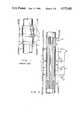
- FIG. 2is a schematic representation of the electrode array of the present invention.
- FIG. 3shows apparatus and a method for forming the electrode and insulation structure.
- FIG. 4shows a modification of FIG. 3 to incorporate expansion partitions in the insulation.
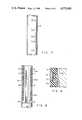
- FIG. 5shows another modified insulation structure.
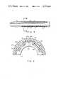
- FIG. 6shows a modification of the FIG. 5 structure.
- FIG. 7shows another modified electrode structure.
- FIGS. 8 and 9show further modifications of electrode and insulation structures.
- a drill string segment 10is shown in borehole 12 which has been drilled in an earth formation F.
- drill string segment 10is a length of steel pipe which has junction structure at each end for joining to other similar drill string segments to form an elongated drill string.
- a length of insulating material 14fills a cylindrical recess or housing 16 on the surface of the drill collar so as to form an annular ring of insulation, the outer surface 18 of which is flush with the outer surface 20 of the drill string segment.
- Insulation 14may be any suitable material to meet the requirements of providing electrical insulation and enduring the environment in which the drill string collar must operate.
- Electrodes A, B 1 , B 2 , M and Nare embedded in the insulating material 14.
- the electrodesmay be any suitable conducting material, such as iron, and they are in the form of annular rings the outer surface of which may be flush with or slightly recessed below the outer surface of insulation layer 14. As will be observed, while the electrodes are embedded in the insulating material 14, they are spaced from the outer surface of recess 16, because the electrodes must be insulated from steel drill string segment 10. Electrodes M and N are positioned between electrodes A and B 1 , while electrode B 2 is spaced from electrode A on the side opposite to electrode B 1 .
- Electrode B 1is the most downhole, i.e., closest to the drill bit, in the array, and electrode B 2 is the most uphole, i.e., farthest from the bit, in the array.
- a constant current source 22is connected to electrode A; electrode B 1 is connected in a return circuit 24 to constant current source 22; electrode B 2 is connected in a return circuit 26 to constant current source 22; and a volt meter 26 is connected between electrodes M and N.
- constant current source 22delivers a current I to electrode A
- a current path I 1is set up from electrode A through formation F to electrode B 1 .
- a leakage current pathwas also set up between electrode A and the drill collar, thus impairing the measurement of apparent formation resistivity.
- the previous leakage currentis collected by the electrode B 2 which cooperates with electrode A to define a second current path I 2 .
- the current I 1flows in circuit 24, while the current I 2 flows in circuit 26, the leakage current to the drill collar is essentially eliminated or reduced to an insignificant amount.
- the value of I 1can be measured directly by an ammeter 30, or the current I 1 can be determined indirectly by measuring the current I 2 in circuit 26 and subtracting from the total current I. In either event, the current value I 1 can be accurately determined, and hence the value of the current I 1 which is responsible for the voltage drop between electrodes M and N ( ⁇ V MN ) is accurately known.
- the voltage drop ⁇ V MNis measured by volt meter 26. With the values for I 1 and ⁇ V MN accurately known, the apparent formation resistivity R f can then be accurately calculated.
- the measured voltage and current valuescan be transmitted to the surface of a borehole by mud pulse telemetry or any other known transmission technique, or a calculation can be made from the voltage and current values by downhole equipment to calculate the apparent formation resistivity for transmission to the surface. In either event the valuable information of apparent formation resistivity can be accurately known at the surface of the well.
- the insulation material 14may be selected from among many different available insulating materials as long as certain minimum fundamental requirements are met.
- the materialmust, of course, be electrically nonductive. It must be stable (i.e., not decompose, soften or otherwise change its characteristics) for temperatures up to about 150° C.; it must be compatible with the drilling mud (which will fill the annulus between the drill string segment and the formation) and it must be resistant to oil or gas which may be present in the drilling mud.
- the insulating materialmust also be compatible with the steel drill collar to the extent that it can be bonded or otherwise securely adhered to the drill collar; it will not shrink significantly relative to the drill collar; and it should have a thermal coefficient of expansion closely matched to that of the drill collar if the material is not resilient.
- the insulating materialmay, for example, be selected from material or synthetic rubber, ceramics, thermosetting molding materials such as polyurethanes, thermoplastic molding materials such as polyamides, polystyrenes and polypropylenes or epoxy materials.
- FIG. 3shows an arrangement in which the array of electrodes embedded in the insulation may be formed.
- support elements 32are mounted in drill string segment 10 at positions spaced apart along the axis of the drill string segment corresponding to the desired locations for the five annular electrodes.
- These support elements 32may be any suitable electrically insulated elements as long as they are shaped or configured to permit the flow of insulating material in the axial direction along the outside of the drill string segment.
- the electrodes A, B 1 , B 2 , M and Nare then positioned on the respective support elements 32. It will be understood that the ring electrodes may have to be split in segments and then joined in order to mount them on the drill string.
- a mold 34is then positioned around the electrode array and fully encloses recess 16 to define recess 16 as a mold cavity.
- a molding materialsuch as a thermosetting polyurethane molding material, is then injected at appropriate pressure and temperature into mold 34 to fill up the mold cavity which corresponds to recess 16.
- the moldis then removed after appropriate curing, and the resulting structure is an array of annular electrodes embedded in an annular length of insulating material recessed in a segment of the drill string.
- FIG. 4a modified version of the configuration of FIG. 3 is shown with an accommodation made to compensate for different coefficients of expansion between the insulating material and the drill string segment. That compensation is accomplished by locating annular expansion blocks or partitions 36 at selected locations along the length of recess 16. Expansion blocks or partitions 36 are resilient and elastic materials (such as synthetic rubber) so that they will compress and expand to absorb differential expansion between the drill collar 10 and the insulating material. The expansion blocks or partitions 36 serve to divide the recess 16 into a series of insulating segments (three in the illustration of FIG. 4). Therefore, it becomes necessary to modify the mold 34 to provide for injection of the uncured insulating material into each of the partitioned segments of recess 16 in order to properly form the segmented insulating structure which results from the FIG. 4 arrangement.
- Expansion blocks or partitions 36are resilient and elastic materials (such as synthetic rubber) so that they will compress and expand to absorb differential expansion between the drill collar 10 and the insulating material.
- the expansion blocks or partitions 36serve to
- the insulating segment of the drill stringoperates in a relatively hostile environment where it is exposed to mud, sand, cuttings, rocks and other formation elements in the borehole being drilled. Because of the hostile environment, it may be desirable to construct the insulation structure out of two different materials, a hard outer sleeve which will be exposed to the hostile drilling environment, and a softer inner sleeve between the hard outer sleeve and the drill collar so that the hard outer sleeve will be able to yield or comply if it encounters a high lateral load, i.e., loading perpendicular to the axis of the drill string segment.
- a multiple sleeve arrangement of this typeis shown in FIG.
- the drill string segment 10has an inner insulating sleeve 38 adjacent the recessed surface of the drill string segment and an outer insulating sleeve 40 adjacent to the inner sleeve 38.
- Outer sleeve 40is a relatively hard sleeve of insulating material, while inner sleeve 38 is a sleeve of relatively soft material.
- sleeve 40will serve to provide abrasion and similar protection, while sleeve 38 will permit absorbtion of lateral loads.
- FIG. 5poses two potential problems.
- One problemis the possibility of angular displacement between outer sleeve 40 and inner sleeve 38 resulting from torsional loads on the outer sleeve.
- the other problemresults from the fact that the electrodes must be contained in the outer sleeve 40. Since the outer sleeve 40 must, of necessity, be thinner than the total thickness of the combined insulating material of sleeves 38 and 40, only a reduced amount of material is available for forming the grooves in sleeve 40 to receive the electrodes, and hence the sleeve 40 is weakened at each of the electrode locations.
- FIG. 6a modified configuration is shown in a cross sectional view with the section taken perpendicular to the axis of the drill string segment.
- drill collar 10is formed with spline segments 42 to form alternating axial lengths of thin and thick segments 43 and 45, respectively.
- the relatively soft inner insulating sleeve 38conforms to the spline configuration of the outer surface of drill string segment 10 in a layer of relatively constant thickness or depth, while the outer harder sleeve of insulating material 40 has thin segments 40a in radial alignment with the splines 42 and thicker segments 40b in radial alignment with the recesses between adjacent splines on the drill string.
- This interlocking sleeve and drill string structure shown in FIG. 6will accommodate lateral deflection of the outer hard sleeve 40 but will reduce or limit the angular displacement between the hard outer sleeve 40 and the drill string 10.
- each electrodeis in the form of a cubic element 44 rather than the annular ring previously described.
- the cubic shaped electrodesare positioned in the thicker sections 40b of the hard outer insulating sleeve 40, so that the entire sleeve is not weakened by a ring electrode. While only one electrode 44 is shown at an axial station in FIG. 6, it will be understood that a plurality of such electrodes may be located at two or more of the thicker segments 40b at each axial electrode station.
- FIG. 7shows still another modification of the structure which is particularly advantageous when employing the arrangement of two sleeves of insulating material as in FIG. 5 or 6.
- a problem which may result from the embedding of hard iron ring electrodes in a hard outer insulating sleeveis that any axial force imposed on the electrode resulting from interference with rock or other debris in the annulus will be fully transmitted to and imposed on the hard outer insulating sleeve. Such loads could, if sufficiently high, cause serious damage to the electrode or the insulating sleeves and could disable the apparent formation resistivity sensing structure.
- This problem of axial loadingis reduced by the electrode structure shown in FIG. 7, wherein each of the electrodes is a diamond shaped segment.
- the electrodeencounters interference with a rock or other piece of debris, the forces will be generated along the inclined surfaces of the electrode, and the electrode will tend to displace slightly in either an axial or lateral direction in response to the force. Such displacement will reduce the likelihood of damage to the electrode or its boundary connections with the insulating material, thus extending the life of the structure.
- the electrodesmust be connected by wire to an electronic package in the drill string (which will also house the voltmeter and ammeter). That wiring may be accomplished in any convenient manner, such as by a protective tube running along the inner surface of recess 16 or by a groove, such as groove 46 in spline segment 42 of the FIG. 6 arrangement. Connection from those protected wires to the electrodes may, for example, be made by means of helicoidally shaped wires to accommodate relative movement between the electrodes and the drill string segment 10.
- FIG. 8shows still another alternate configuration for the insulation and electrode structure.
- the insulation sleeveis made up of a band 48 of elastomeric nonconductive material.
- Band 48could be formed from a plurality of interlocking rings or segments 48(a), 48(b) and 48(c), for example.
- the electrodesare composed of rings or bands of conductive elastomeric material 49 in appropriately located recesses in the band of nonconductive material.
- Elastomeric materials 48 and 49may be the same or similar base materials to match coefficients of expansion, with the conductive bands 49 being filled with silver, carbon or other conductive material to make the bands conductive electrodes.
- the band of nonconductive and conductive elastomeric materialmay be mounted on the drill collar segment by being molded in place, or, if desired, by being stretched and slipped over the thicker section of the drill string segment and then released to contract into place in the recess 16.
- a tube 50is shown in FIG. 8, the tube 50 housing appropriate wiring which is connected by helical segments to each of the electrodes. Only three of the electrodes are shown in FIG. 8, but it will be understood that two additional electrodes would be employed to complete the array of FIG. 2.
- FIG. 9an improved detail of effecting electrical connection to the elastomeric electrode of FIG. 8 is shown.
- a recess or groove 51 in the nonconductive elastomer 48(b)is coated with a resilient conductive material, such as a band of resilient metallic turnings (as in the nature of steel wood) or woven conductive cable indicated at 52.
- the helical circuit wireis physically and electrically connected to this ring of conductive turnings or steel wool material 52, and the material 52 forms multiple electrical contacts with the conductive elastomer electrode. In this way, electrical continuity from the electrode to the circuit wire is assured.
Landscapes
- Engineering & Computer Science (AREA)
- Life Sciences & Earth Sciences (AREA)
- Geology (AREA)
- General Life Sciences & Earth Sciences (AREA)
- Physics & Mathematics (AREA)
- Environmental & Geological Engineering (AREA)
- Mining & Mineral Resources (AREA)
- Remote Sensing (AREA)
- General Physics & Mathematics (AREA)
- Geophysics (AREA)
- Mechanical Engineering (AREA)
- Fluid Mechanics (AREA)
- Geochemistry & Mineralogy (AREA)
- Geophysics And Detection Of Objects (AREA)
Abstract
Description
Claims (8)
Priority Applications (1)
| Application Number | Priority Date | Filing Date | Title |
|---|---|---|---|
| US06/727,362US4575681A (en) | 1982-11-12 | 1985-04-25 | Insulating and electrode structure for a drill string |
Applications Claiming Priority (2)
| Application Number | Priority Date | Filing Date | Title |
|---|---|---|---|
| US44110782A | 1982-11-12 | 1982-11-12 | |
| US06/727,362US4575681A (en) | 1982-11-12 | 1985-04-25 | Insulating and electrode structure for a drill string |
Related Parent Applications (1)
| Application Number | Title | Priority Date | Filing Date |
|---|---|---|---|
| US44110782AContinuation | 1982-11-12 | 1982-11-12 |
Publications (1)
| Publication Number | Publication Date |
|---|---|
| US4575681Atrue US4575681A (en) | 1986-03-11 |
Family
ID=27032676
Family Applications (1)
| Application Number | Title | Priority Date | Filing Date |
|---|---|---|---|
| US06/727,362Expired - Fee RelatedUS4575681A (en) | 1982-11-12 | 1985-04-25 | Insulating and electrode structure for a drill string |
Country Status (1)
| Country | Link |
|---|---|
| US (1) | US4575681A (en) |
Cited By (46)
| Publication number | Priority date | Publication date | Assignee | Title |
|---|---|---|---|---|
| US5235285A (en)* | 1991-10-31 | 1993-08-10 | Schlumberger Technology Corporation | Well logging apparatus having toroidal induction antenna for measuring, while drilling, resistivity of earth formations |
| US5325714A (en)* | 1993-05-12 | 1994-07-05 | Baker Hughes Incorporated | Steerable motor system with integrated formation evaluation logging capacity |
| US5339037A (en)* | 1992-10-09 | 1994-08-16 | Schlumberger Technology Corporation | Apparatus and method for determining the resistivity of earth formations |
| US5463320A (en)* | 1992-10-09 | 1995-10-31 | Schlumberger Technology Corporation | Apparatus and method for determining the resitivity of underground formations surrounding a borehole |
| US20020058332A1 (en)* | 2000-09-15 | 2002-05-16 | California Institute Of Technology | Microfabricated crossflow devices and methods |
| US20020105334A1 (en)* | 2001-01-26 | 2002-08-08 | Compagnie Du Sol | Drill string enabling information to be transmitted |
| US20020109114A1 (en)* | 2000-11-06 | 2002-08-15 | California Institute Of Technology | Electrostatic valves for microfluidic devices |
| US20030080442A1 (en)* | 2001-08-30 | 2003-05-01 | Fluidigm Corp. | Electrostatic/electrostrictive actuation of elastomer structures using compliant electrodes |
| US20040072278A1 (en)* | 2002-04-01 | 2004-04-15 | Fluidigm Corporation | Microfluidic particle-analysis systems |
| US20040180377A1 (en)* | 2002-06-24 | 2004-09-16 | Fluidigm | Recirculating fluidic network and methods for using the same |
| US20040229349A1 (en)* | 2002-04-01 | 2004-11-18 | Fluidigm Corporation | Microfluidic particle-analysis systems |
| US20050019792A1 (en)* | 2001-11-30 | 2005-01-27 | Fluidigm Corporation | Microfluidic device and methods of using same |
| US20050065735A1 (en)* | 2000-06-27 | 2005-03-24 | Fluidigm Corporation | Microfluidic design automation method and system |
| US20050084421A1 (en)* | 2003-04-03 | 2005-04-21 | Fluidigm Corporation | Microfluidic devices and methods of using same |
| US20050129581A1 (en)* | 2003-04-03 | 2005-06-16 | Fluidigm Corporation | Microfluidic devices and methods of using same |
| US20050221373A1 (en)* | 2001-04-06 | 2005-10-06 | California Institute Of Technology | Nucleic acid amplification using microfluidic devices |
| US20050252773A1 (en)* | 2003-04-03 | 2005-11-17 | Fluidigm Corporation | Thermal reaction device and method for using the same |
| US20050279497A1 (en)* | 2004-06-18 | 2005-12-22 | Schlumberger Technology Corporation | Completion apparatus for measuring streaming potentials and determining earth formation characteristics |
| US20050280419A1 (en)* | 2004-06-18 | 2005-12-22 | Schlumberger Technology Corporation | While-drilling apparatus for measuring streaming potentials and determining earth formation characteristics |
| US20050279495A1 (en)* | 2004-06-18 | 2005-12-22 | Schlumberger Technology Corporation, Incorporated In The State Of Texas | Methods for locating formation fractures and monitoring well completion using streaming potential transients information |
| US20050279161A1 (en)* | 2004-06-18 | 2005-12-22 | Schlumberger Technology Corporation | Wireline apparatus for measuring streaming potentials and determining earth formation characteristics |
| US20060089804A1 (en)* | 2004-06-18 | 2006-04-27 | Schlumberger Technology Corporation | While-drilling methodology for determining earth formation characteristics and other useful information based upon streaming potential measurements |
| US20060099116A1 (en)* | 2000-10-13 | 2006-05-11 | Mycometrix Corporation | Microfluidic-based electrospray source for analytical devices |
| US20060125474A1 (en)* | 2004-06-18 | 2006-06-15 | Schlumberger Technology Corporation | While-drilling methodology for estimating formation pressure based upon streaming potential measurements |
| US7192629B2 (en) | 2001-10-11 | 2007-03-20 | California Institute Of Technology | Devices utilizing self-assembled gel and method of manufacture |
| US20070141599A1 (en)* | 1997-09-23 | 2007-06-21 | California Institute Of Technology | Methods and systems for molecular fingerprinting |
| US20070170924A1 (en)* | 2004-06-18 | 2007-07-26 | Schlumberger Technology Corporation | While-drilling apparatus for measuring streaming potentials and determining earth formation characteristics and other useful information |
| US20070290689A1 (en)* | 2006-05-01 | 2007-12-20 | Schlumberger Technology Corporation | Logging Tool Sonde Sleeve |
| US7413712B2 (en) | 2003-08-11 | 2008-08-19 | California Institute Of Technology | Microfluidic rotary flow reactor matrix |
| US20090153355A1 (en)* | 2005-02-28 | 2009-06-18 | Applied Technologies Associates, Inc. | Electric field communication for short range data transmission in a borehole |
| US7586310B2 (en) | 2004-06-18 | 2009-09-08 | Schlumberger Technology Corporation | While-drilling apparatus for measuring streaming potentials and determining earth formation characteristics and other useful information |
| US20090242274A1 (en)* | 2004-06-18 | 2009-10-01 | Schlumberger Technology Corporation | Apparatus for measuring streaming potentials and determining earth formation characteristics |
| US20090291435A1 (en)* | 2005-03-18 | 2009-11-26 | Unger Marc A | Thermal reaction device and method for using the same |
| US20090299545A1 (en)* | 2003-05-20 | 2009-12-03 | Fluidigm Corporation | Method and system for microfluidic device and imaging thereof |
| US20100119154A1 (en)* | 2003-07-28 | 2010-05-13 | Fluidigm Corporation | Image processing method and system for microfluidic devices |
| US20100154890A1 (en)* | 2002-09-25 | 2010-06-24 | California Institute Of Technology | Microfluidic Large Scale Integration |
| US7867454B2 (en) | 2003-04-03 | 2011-01-11 | Fluidigm Corporation | Thermal reaction device and method for using the same |
| US20110083838A1 (en)* | 2009-10-08 | 2011-04-14 | Labrecque Douglas J | System and method for electrical resistivity tomography and/or electrical impedance tomography |
| US8440093B1 (en) | 2001-10-26 | 2013-05-14 | Fuidigm Corporation | Methods and devices for electronic and magnetic sensing of the contents of microfluidic flow channels |
| US20140285205A1 (en)* | 2013-03-22 | 2014-09-25 | Oliden Technology, Llc | Well logging apparatus and system |
| US8871446B2 (en) | 2002-10-02 | 2014-10-28 | California Institute Of Technology | Microfluidic nucleic acid analysis |
| GB2516572A (en)* | 2009-10-08 | 2015-01-28 | Multi Phase Technologies Llc | System and method for electrical resistivity tomography and/or electrical impedance tomography |
| EP2572217A4 (en)* | 2010-05-21 | 2016-11-23 | Halliburton Energy Services Inc | Systems and methods for downhole bha insulation in magnetic ranging applications |
| EP3170969A1 (en)* | 2015-11-17 | 2017-05-24 | Services Pétroliers Schlumberger | Encapsulated sensors and electronics |
| AU2016200837B2 (en)* | 2010-05-21 | 2017-08-17 | Halliburton Energy Services, Inc. | Systems and methods for downhole bha insulation in magnetic ranging applications |
| US20180371862A1 (en)* | 2016-09-15 | 2018-12-27 | Halliburton Energy Services, Inc. | Downhole wire routing |
Citations (6)
| Publication number | Priority date | Publication date | Assignee | Title |
|---|---|---|---|---|
| US2400678A (en)* | 1943-11-27 | 1946-05-21 | Shell Dev | Method and apparatus for electrically logging wells |
| US2941784A (en)* | 1955-07-05 | 1960-06-21 | Atlantic Refining Co | Logging while drilling |
| US3134069A (en)* | 1959-01-30 | 1964-05-19 | Texaco Inc | Well logging apparatus having detector means in a rotatable casing mounted within a drill string for simultaneous drilling and logging |
| US3379963A (en)* | 1965-04-02 | 1968-04-23 | Schlumberger Technology Corp | Well logging pad member constructed to contorm to borehole wall curvature |
| US4286217A (en)* | 1979-02-01 | 1981-08-25 | Schlumberger Technology Corporation | Device for electrode-type electrical logging tools and tool incorporating said device |
| US4356629A (en)* | 1980-04-21 | 1982-11-02 | Exploration Logging, Inc. | Method of making well logging apparatus |
- 1985
- 1985-04-25USUS06/727,362patent/US4575681A/ennot_activeExpired - Fee Related
Patent Citations (6)
| Publication number | Priority date | Publication date | Assignee | Title |
|---|---|---|---|---|
| US2400678A (en)* | 1943-11-27 | 1946-05-21 | Shell Dev | Method and apparatus for electrically logging wells |
| US2941784A (en)* | 1955-07-05 | 1960-06-21 | Atlantic Refining Co | Logging while drilling |
| US3134069A (en)* | 1959-01-30 | 1964-05-19 | Texaco Inc | Well logging apparatus having detector means in a rotatable casing mounted within a drill string for simultaneous drilling and logging |
| US3379963A (en)* | 1965-04-02 | 1968-04-23 | Schlumberger Technology Corp | Well logging pad member constructed to contorm to borehole wall curvature |
| US4286217A (en)* | 1979-02-01 | 1981-08-25 | Schlumberger Technology Corporation | Device for electrode-type electrical logging tools and tool incorporating said device |
| US4356629A (en)* | 1980-04-21 | 1982-11-02 | Exploration Logging, Inc. | Method of making well logging apparatus |
Cited By (124)
| Publication number | Priority date | Publication date | Assignee | Title |
|---|---|---|---|---|
| US5339036A (en)* | 1991-10-31 | 1994-08-16 | Schlumberger Technology Corporation | Logging while drilling apparatus with blade mounted electrode for determining resistivity of surrounding formation |
| US5359324A (en)* | 1991-10-31 | 1994-10-25 | Schlumberger Technology Corporation | Well logging apparatus for investigating earth formations |
| US5235285A (en)* | 1991-10-31 | 1993-08-10 | Schlumberger Technology Corporation | Well logging apparatus having toroidal induction antenna for measuring, while drilling, resistivity of earth formations |
| US5339037A (en)* | 1992-10-09 | 1994-08-16 | Schlumberger Technology Corporation | Apparatus and method for determining the resistivity of earth formations |
| US5463320A (en)* | 1992-10-09 | 1995-10-31 | Schlumberger Technology Corporation | Apparatus and method for determining the resitivity of underground formations surrounding a borehole |
| US5325714A (en)* | 1993-05-12 | 1994-07-05 | Baker Hughes Incorporated | Steerable motor system with integrated formation evaluation logging capacity |
| US20070141599A1 (en)* | 1997-09-23 | 2007-06-21 | California Institute Of Technology | Methods and systems for molecular fingerprinting |
| US20100196892A1 (en)* | 1997-09-23 | 2010-08-05 | California Institute Of Technology | Methods and Systems for Molecular Fingerprinting |
| US9926521B2 (en) | 2000-06-27 | 2018-03-27 | Fluidigm Corporation | Microfluidic particle-analysis systems |
| US20050065735A1 (en)* | 2000-06-27 | 2005-03-24 | Fluidigm Corporation | Microfluidic design automation method and system |
| US7526741B2 (en) | 2000-06-27 | 2009-04-28 | Fluidigm Corporation | Microfluidic design automation method and system |
| US20060036416A1 (en)* | 2000-06-27 | 2006-02-16 | Fluidigm Corporation | Computer aided design method and system for developing a microfluidic system |
| US8592215B2 (en) | 2000-09-15 | 2013-11-26 | California Institute Of Technology | Microfabricated crossflow devices and methods |
| US8658368B2 (en) | 2000-09-15 | 2014-02-25 | California Institute Of Technology | Microfabricated crossflow devices and methods |
| US8658367B2 (en) | 2000-09-15 | 2014-02-25 | California Institute Of Technology | Microfabricated crossflow devices and methods |
| US7294503B2 (en) | 2000-09-15 | 2007-11-13 | California Institute Of Technology | Microfabricated crossflow devices and methods |
| US20090035838A1 (en)* | 2000-09-15 | 2009-02-05 | California Institute Of Technology | Microfabricated Crossflow Devices and Methods |
| US8445210B2 (en) | 2000-09-15 | 2013-05-21 | California Institute Of Technology | Microfabricated crossflow devices and methods |
| US8252539B2 (en) | 2000-09-15 | 2012-08-28 | California Institute Of Technology | Microfabricated crossflow devices and methods |
| US20020058332A1 (en)* | 2000-09-15 | 2002-05-16 | California Institute Of Technology | Microfabricated crossflow devices and methods |
| US20060099116A1 (en)* | 2000-10-13 | 2006-05-11 | Mycometrix Corporation | Microfluidic-based electrospray source for analytical devices |
| US7442556B2 (en) | 2000-10-13 | 2008-10-28 | Fluidigm Corporation | Microfluidic-based electrospray source for analytical devices with a rotary fluid flow channel for sample preparation |
| US20020109114A1 (en)* | 2000-11-06 | 2002-08-15 | California Institute Of Technology | Electrostatic valves for microfluidic devices |
| US7232109B2 (en) | 2000-11-06 | 2007-06-19 | California Institute Of Technology | Electrostatic valves for microfluidic devices |
| US6958703B2 (en)* | 2001-01-26 | 2005-10-25 | Compagnie Du Sol | Drill string enabling information to be transmitted |
| US20020105334A1 (en)* | 2001-01-26 | 2002-08-08 | Compagnie Du Sol | Drill string enabling information to be transmitted |
| US7833708B2 (en) | 2001-04-06 | 2010-11-16 | California Institute Of Technology | Nucleic acid amplification using microfluidic devices |
| US20050221373A1 (en)* | 2001-04-06 | 2005-10-06 | California Institute Of Technology | Nucleic acid amplification using microfluidic devices |
| US8486636B2 (en) | 2001-04-06 | 2013-07-16 | California Institute Of Technology | Nucleic acid amplification using microfluidic devices |
| US8936764B2 (en) | 2001-04-06 | 2015-01-20 | California Institute Of Technology | Nucleic acid amplification using microfluidic devices |
| US20030080442A1 (en)* | 2001-08-30 | 2003-05-01 | Fluidigm Corp. | Electrostatic/electrostrictive actuation of elastomer structures using compliant electrodes |
| US20060118895A1 (en)* | 2001-08-30 | 2006-06-08 | Fluidigm Corporation | Electrostatic/electrostrictive actuation of elastomer structures using compliant electrodes |
| US7291512B2 (en) | 2001-08-30 | 2007-11-06 | Fluidigm Corporation | Electrostatic/electrostrictive actuation of elastomer structures using compliant electrodes |
| US7075162B2 (en)* | 2001-08-30 | 2006-07-11 | Fluidigm Corporation | Electrostatic/electrostrictive actuation of elastomer structures using compliant electrodes |
| US7192629B2 (en) | 2001-10-11 | 2007-03-20 | California Institute Of Technology | Devices utilizing self-assembled gel and method of manufacture |
| US8845914B2 (en) | 2001-10-26 | 2014-09-30 | Fluidigm Corporation | Methods and devices for electronic sensing |
| US9103761B2 (en) | 2001-10-26 | 2015-08-11 | Fluidigm Corporation | Methods and devices for electronic sensing |
| US8440093B1 (en) | 2001-10-26 | 2013-05-14 | Fuidigm Corporation | Methods and devices for electronic and magnetic sensing of the contents of microfluidic flow channels |
| US20050019792A1 (en)* | 2001-11-30 | 2005-01-27 | Fluidigm Corporation | Microfluidic device and methods of using same |
| US20110189678A1 (en)* | 2001-11-30 | 2011-08-04 | Fluidigm Corporation | Microfluidic Device and Methods of Using Same |
| US7837946B2 (en) | 2001-11-30 | 2010-11-23 | Fluidigm Corporation | Microfluidic device and methods of using same |
| US8343442B2 (en) | 2001-11-30 | 2013-01-01 | Fluidigm Corporation | Microfluidic device and methods of using same |
| US7691333B2 (en) | 2001-11-30 | 2010-04-06 | Fluidigm Corporation | Microfluidic device and methods of using same |
| US8658418B2 (en) | 2002-04-01 | 2014-02-25 | Fluidigm Corporation | Microfluidic particle-analysis systems |
| US20040229349A1 (en)* | 2002-04-01 | 2004-11-18 | Fluidigm Corporation | Microfluidic particle-analysis systems |
| US20100120077A1 (en)* | 2002-04-01 | 2010-05-13 | Fluidigm Corporation | Microfluidic particle-analysis systems |
| US7452726B2 (en) | 2002-04-01 | 2008-11-18 | Fluidigm Corporation | Microfluidic particle-analysis systems |
| US7312085B2 (en) | 2002-04-01 | 2007-12-25 | Fluidigm Corporation | Microfluidic particle-analysis systems |
| US20040072278A1 (en)* | 2002-04-01 | 2004-04-15 | Fluidigm Corporation | Microfluidic particle-analysis systems |
| US20040180377A1 (en)* | 2002-06-24 | 2004-09-16 | Fluidigm | Recirculating fluidic network and methods for using the same |
| US20060086309A1 (en)* | 2002-06-24 | 2006-04-27 | Fluiding Corporation | Recirculating fluidic network and methods for using the same |
| US9714443B2 (en) | 2002-09-25 | 2017-07-25 | California Institute Of Technology | Microfabricated structure having parallel and orthogonal flow channels controlled by row and column multiplexors |
| US20100154890A1 (en)* | 2002-09-25 | 2010-06-24 | California Institute Of Technology | Microfluidic Large Scale Integration |
| US9579650B2 (en) | 2002-10-02 | 2017-02-28 | California Institute Of Technology | Microfluidic nucleic acid analysis |
| US8871446B2 (en) | 2002-10-02 | 2014-10-28 | California Institute Of Technology | Microfluidic nucleic acid analysis |
| US10940473B2 (en) | 2002-10-02 | 2021-03-09 | California Institute Of Technology | Microfluidic nucleic acid analysis |
| US10328428B2 (en) | 2002-10-02 | 2019-06-25 | California Institute Of Technology | Apparatus for preparing cDNA libraries from single cells |
| US7666361B2 (en) | 2003-04-03 | 2010-02-23 | Fluidigm Corporation | Microfluidic devices and methods of using same |
| US20090061428A1 (en)* | 2003-04-03 | 2009-03-05 | Fluidigm Corporation | Thermal Reaction Device and Method for Using the Same |
| US7604965B2 (en) | 2003-04-03 | 2009-10-20 | Fluidigm Corporation | Thermal reaction device and method for using the same |
| US20050252773A1 (en)* | 2003-04-03 | 2005-11-17 | Fluidigm Corporation | Thermal reaction device and method for using the same |
| US8007746B2 (en) | 2003-04-03 | 2011-08-30 | Fluidigm Corporation | Microfluidic devices and methods of using same |
| US7476363B2 (en) | 2003-04-03 | 2009-01-13 | Fluidigm Corporation | Microfluidic devices and methods of using same |
| US20050129581A1 (en)* | 2003-04-03 | 2005-06-16 | Fluidigm Corporation | Microfluidic devices and methods of using same |
| US8247178B2 (en) | 2003-04-03 | 2012-08-21 | Fluidigm Corporation | Thermal reaction device and method for using the same |
| US10131934B2 (en) | 2003-04-03 | 2018-11-20 | Fluidigm Corporation | Thermal reaction device and method for using the same |
| US7867454B2 (en) | 2003-04-03 | 2011-01-11 | Fluidigm Corporation | Thermal reaction device and method for using the same |
| US20090142236A1 (en)* | 2003-04-03 | 2009-06-04 | Fluidigm Corporation | Microfluidic Devices and Methods of Using Same |
| US20050084421A1 (en)* | 2003-04-03 | 2005-04-21 | Fluidigm Corporation | Microfluidic devices and methods of using same |
| US7749737B2 (en) | 2003-04-03 | 2010-07-06 | Fluidigm Corporation | Thermal reaction device and method for using the same |
| US20100184202A1 (en)* | 2003-04-03 | 2010-07-22 | Fluidigm Corporation | Thermal Reaction Device and Method for Using the Same |
| US9150913B2 (en) | 2003-04-03 | 2015-10-06 | Fluidigm Corporation | Thermal reaction device and method for using the same |
| US7695683B2 (en) | 2003-05-20 | 2010-04-13 | Fluidigm Corporation | Method and system for microfluidic device and imaging thereof |
| US8808640B2 (en) | 2003-05-20 | 2014-08-19 | Fluidigm Corporation | Method and system for microfluidic device and imaging thereof |
| US8367016B2 (en) | 2003-05-20 | 2013-02-05 | Fluidigm Corporation | Method and system for microfluidic device and imaging thereof |
| US8105550B2 (en) | 2003-05-20 | 2012-01-31 | Fluidigm Corporation | Method and system for microfluidic device and imaging thereof |
| US20090299545A1 (en)* | 2003-05-20 | 2009-12-03 | Fluidigm Corporation | Method and system for microfluidic device and imaging thereof |
| US7792345B2 (en) | 2003-07-28 | 2010-09-07 | Fluidigm Corporation | Image processing method and system for microfluidic devices |
| US20100119154A1 (en)* | 2003-07-28 | 2010-05-13 | Fluidigm Corporation | Image processing method and system for microfluidic devices |
| US20090087356A1 (en)* | 2003-08-11 | 2009-04-02 | California Institute Of Technology | Microfluidic Rotary Flow Reactor Matrix |
| US20100104477A1 (en)* | 2003-08-11 | 2010-04-29 | California Institute Of Technology | Microfluidic rotary flow reactor matrix |
| US7964139B2 (en) | 2003-08-11 | 2011-06-21 | California Institute Of Technology | Microfluidic rotary flow reactor matrix |
| US7413712B2 (en) | 2003-08-11 | 2008-08-19 | California Institute Of Technology | Microfluidic rotary flow reactor matrix |
| US7520324B2 (en) | 2004-06-18 | 2009-04-21 | Schlumberger Technology Corporation | Completion apparatus for measuring streaming potentials and determining earth formation characteristics |
| US20050279161A1 (en)* | 2004-06-18 | 2005-12-22 | Schlumberger Technology Corporation | Wireline apparatus for measuring streaming potentials and determining earth formation characteristics |
| US20050280419A1 (en)* | 2004-06-18 | 2005-12-22 | Schlumberger Technology Corporation | While-drilling apparatus for measuring streaming potentials and determining earth formation characteristics |
| US20050279497A1 (en)* | 2004-06-18 | 2005-12-22 | Schlumberger Technology Corporation | Completion apparatus for measuring streaming potentials and determining earth formation characteristics |
| US7243718B2 (en) | 2004-06-18 | 2007-07-17 | Schlumberger Technology Corporation | Methods for locating formation fractures and monitoring well completion using streaming potential transients information |
| US8302687B2 (en) | 2004-06-18 | 2012-11-06 | Schlumberger Technology Corporation | Apparatus for measuring streaming potentials and determining earth formation characteristics |
| US20050279495A1 (en)* | 2004-06-18 | 2005-12-22 | Schlumberger Technology Corporation, Incorporated In The State Of Texas | Methods for locating formation fractures and monitoring well completion using streaming potential transients information |
| US20090242274A1 (en)* | 2004-06-18 | 2009-10-01 | Schlumberger Technology Corporation | Apparatus for measuring streaming potentials and determining earth formation characteristics |
| US7586310B2 (en) | 2004-06-18 | 2009-09-08 | Schlumberger Technology Corporation | While-drilling apparatus for measuring streaming potentials and determining earth formation characteristics and other useful information |
| US20090166024A1 (en)* | 2004-06-18 | 2009-07-02 | Schlumberger Technology Corporation | Completion apparatus for measuring streaming potentials and determining earth formation characteristics |
| US20070170924A1 (en)* | 2004-06-18 | 2007-07-26 | Schlumberger Technology Corporation | While-drilling apparatus for measuring streaming potentials and determining earth formation characteristics and other useful information |
| US7891417B2 (en)* | 2004-06-18 | 2011-02-22 | Schlumberger Technology Corporation | Completion apparatus for measuring streaming potentials and determining earth formation characteristics |
| US6978672B1 (en)* | 2004-06-18 | 2005-12-27 | Schlumberger Technology Corporation | Wireline apparatus for measuring steaming potentials and determining earth formation characteristics |
| US7466136B2 (en) | 2004-06-18 | 2008-12-16 | Schlumberger Technology Corporation | While-drilling methodology for determining earth formation characteristics and other useful information based upon streaming potential measurements |
| US7388380B2 (en) | 2004-06-18 | 2008-06-17 | Schlumberger Technology | While-drilling apparatus for measuring streaming potentials and determining earth formation characteristics and other useful information |
| US7301345B2 (en) | 2004-06-18 | 2007-11-27 | Schlumberger Technology Corporation | While-drilling methodology for estimating formation pressure based upon streaming potential measurements |
| US20060089804A1 (en)* | 2004-06-18 | 2006-04-27 | Schlumberger Technology Corporation | While-drilling methodology for determining earth formation characteristics and other useful information based upon streaming potential measurements |
| US20060125474A1 (en)* | 2004-06-18 | 2006-06-15 | Schlumberger Technology Corporation | While-drilling methodology for estimating formation pressure based upon streaming potential measurements |
| US7233150B2 (en) | 2004-06-18 | 2007-06-19 | Schlumberger Technology Corporation | While-drilling apparatus for measuring streaming potentials and determining earth formation characteristics |
| US20090153355A1 (en)* | 2005-02-28 | 2009-06-18 | Applied Technologies Associates, Inc. | Electric field communication for short range data transmission in a borehole |
| US8258976B2 (en)* | 2005-02-28 | 2012-09-04 | Scientific Drilling International, Inc. | Electric field communication for short range data transmission in a borehole |
| US8828663B2 (en) | 2005-03-18 | 2014-09-09 | Fluidigm Corporation | Thermal reaction device and method for using the same |
| US20090291435A1 (en)* | 2005-03-18 | 2009-11-26 | Unger Marc A | Thermal reaction device and method for using the same |
| US7986145B2 (en)* | 2006-05-01 | 2011-07-26 | Schlumberger Technology Corporation | Logging tool sonde sleeve |
| US20070290689A1 (en)* | 2006-05-01 | 2007-12-20 | Schlumberger Technology Corporation | Logging Tool Sonde Sleeve |
| US8773134B2 (en) | 2006-05-01 | 2014-07-08 | Schlumberger Technology Corporation | Logging tool sonde sleeve |
| US20110083838A1 (en)* | 2009-10-08 | 2011-04-14 | Labrecque Douglas J | System and method for electrical resistivity tomography and/or electrical impedance tomography |
| GB2486154B (en)* | 2009-10-08 | 2015-03-04 | Multi Phase Technologies Llc | System and method for electrical resistivity and/or impedance tomography in a borehole |
| GB2516572A (en)* | 2009-10-08 | 2015-01-28 | Multi Phase Technologies Llc | System and method for electrical resistivity tomography and/or electrical impedance tomography |
| GB2486154A (en)* | 2009-10-08 | 2012-06-06 | Multi Phase Technologies Llc | System and method for electrical resistivity and/or impedance tomography in a borehole |
| WO2011044534A3 (en)* | 2009-10-08 | 2011-06-30 | Multi-Phase Technologies, Llc | System and method for electrical resistivity and/or impedance tomography in a borehole |
| US8733432B2 (en) | 2009-10-08 | 2014-05-27 | Multi-Phase Technologies, Llc | System and method for electrical resistivity tomography and/or electrical impedance tomography |
| AU2016200837B2 (en)* | 2010-05-21 | 2017-08-17 | Halliburton Energy Services, Inc. | Systems and methods for downhole bha insulation in magnetic ranging applications |
| US10465503B2 (en) | 2010-05-21 | 2019-11-05 | Halliburton Energy Services, Inc. | Systems and methods for downhole BHA insulation in magnetic ranging applications |
| EP2572217A4 (en)* | 2010-05-21 | 2016-11-23 | Halliburton Energy Services Inc | Systems and methods for downhole bha insulation in magnetic ranging applications |
| US20140285205A1 (en)* | 2013-03-22 | 2014-09-25 | Oliden Technology, Llc | Well logging apparatus and system |
| US9213125B2 (en)* | 2013-03-22 | 2015-12-15 | Oliden Technology, Llc | Well logging apparatus and system |
| EP3170969A1 (en)* | 2015-11-17 | 2017-05-24 | Services Pétroliers Schlumberger | Encapsulated sensors and electronics |
| US10605071B2 (en) | 2015-11-17 | 2020-03-31 | Schlumberger Technology Corporation | Encapsulated sensors and electronics |
| US20180371862A1 (en)* | 2016-09-15 | 2018-12-27 | Halliburton Energy Services, Inc. | Downhole wire routing |
| US10927632B2 (en)* | 2016-09-15 | 2021-02-23 | Halliburton Energy Services, Inc. | Downhole wire routing |
Similar Documents
| Publication | Publication Date | Title |
|---|---|---|
| US4575681A (en) | Insulating and electrode structure for a drill string | |
| US4570123A (en) | Electrode array for measurement of borehole resistivity | |
| US4738812A (en) | Method of forming an electrode structure | |
| US4618828A (en) | Insulating segment for a drill string electrode structure | |
| US3518608A (en) | Telemetry drill pipe with thread electrode | |
| US3696332A (en) | Telemetering drill string with self-cleaning connectors | |
| CA2711853C (en) | Electromagnetic telemetry assembly with protected antenna | |
| US4766442A (en) | Antenna structure for use with a transmitter located at a great depth | |
| CN101592031B (en) | A combined propagation and lateral resistivity downhole tool | |
| CA2890603C (en) | Downhole electromagnetic telemetry apparatus | |
| US20040178797A1 (en) | Centralizer including measurement means | |
| US5631563A (en) | Resistivity antenna shield, wear band and stabilizer assembly for measuring-while-drilling tool | |
| US20070290689A1 (en) | Logging Tool Sonde Sleeve | |
| CA2549541C (en) | Mass isolation joint for electrically isolating a downhole tool | |
| US20110254695A1 (en) | Tapered thread em gap sub self-aligning means and method | |
| US5157331A (en) | Enhanced wide aperture groove for antenna of downhole resistivity tool | |
| US3057409A (en) | Well casing | |
| JP2007518906A (en) | Drill column for deep well and drill pipe and bush for the drill column | |
| GB2129946A (en) | Electrode structure for drill string | |
| CA1227538A (en) | Electrode structure to measure borehole resistivity | |
| CA1219039A (en) | Electrode structure to measure borehole resistivity | |
| US3162806A (en) | Bore logging apparatus including conductive housings, mechanically coupled by an electrically insulating binding agent | |
| JPS59225500A (en) | Signal transmitter | |
| CA1077081A (en) | Pipe section for use in borehole operations and method of manufacturing the same | |
| MXPA06007742A (en) | Drill stem for deep drillings |
Legal Events
| Date | Code | Title | Description |
|---|---|---|---|
| FPAY | Fee payment | Year of fee payment:4 | |
| AS | Assignment | Owner name:BAKER HUGHES MINING TOOLS, INC., TEXAS Free format text:MERGER;ASSIGNOR:EASTMAN TELECO COMPANY;REEL/FRAME:006483/0250 Effective date:19930101 Owner name:BAKER HUGHES PRODUCTION TOOLS, INC., TEXAS Free format text:MERGER;ASSIGNOR:BAKER HUGHES DRILLING TECHNOLOGIES, INC.;REEL/FRAME:006483/0260 Effective date:19930315 Owner name:BAKER HUGHES INCORPORATED, TEXAS Free format text:ASSIGNMENT OF ASSIGNORS INTEREST.;ASSIGNOR:BAKER HUGHES INTEQ, INC.;REEL/FRAME:006483/0267 Effective date:19930401 Owner name:BAKER HUGHES INTEQ, INC., TEXAS Free format text:CHANGE OF NAME;ASSIGNOR:BAKER HUGHES PRODUCTION TOOLS, INC.;REEL/FRAME:006483/0264 Effective date:19930310 Owner name:BAKER HUGHES DRILLING TECHNOLOGIES, INC., TEXAS Free format text:CHANGE OF NAME;ASSIGNOR:BAKER HUGHES MINING TOOLS, INC.;REEL/FRAME:006483/0256 Effective date:19930105 Owner name:EASTMAN TELECO COMPANY, TEXAS Free format text:MERGER;ASSIGNOR:TELECO OILFIELD SERVICES, INC.;REEL/FRAME:006483/0244 Effective date:19920701 | |
| REMI | Maintenance fee reminder mailed | ||
| LAPS | Lapse for failure to pay maintenance fees | ||
| FP | Lapsed due to failure to pay maintenance fee | Effective date:19940313 | |
| FEPP | Fee payment procedure | Free format text:PAYOR NUMBER ASSIGNED (ORIGINAL EVENT CODE: ASPN); ENTITY STATUS OF PATENT OWNER: LARGE ENTITY | |
| STCH | Information on status: patent discontinuation | Free format text:PATENT EXPIRED DUE TO NONPAYMENT OF MAINTENANCE FEES UNDER 37 CFR 1.362 |